US1237850A - Adjustable chair. - Google Patents
Adjustable chair. Download PDFInfo
- Publication number
- US1237850A US1237850A US4811015A US4811015A US1237850A US 1237850 A US1237850 A US 1237850A US 4811015 A US4811015 A US 4811015A US 4811015 A US4811015 A US 4811015A US 1237850 A US1237850 A US 1237850A
- Authority
- US
- United States
- Prior art keywords
- chair
- frame
- plates
- studs
- stud
- Prior art date
- Legal status (The legal status is an assumption and is not a legal conclusion. Google has not performed a legal analysis and makes no representation as to the accuracy of the status listed.)
- Expired - Lifetime
Links
- 238000006073 displacement reaction Methods 0.000 description 3
- 238000010276 construction Methods 0.000 description 2
- 235000006629 Prosopis spicigera Nutrition 0.000 description 1
- 240000000037 Prosopis spicigera Species 0.000 description 1
- 239000004568 cement Substances 0.000 description 1
- 230000000694 effects Effects 0.000 description 1
- 230000000284 resting effect Effects 0.000 description 1
- 238000010079 rubber tapping Methods 0.000 description 1
Images

Classifications
-
- A—HUMAN NECESSITIES
- A47—FURNITURE; DOMESTIC ARTICLES OR APPLIANCES; COFFEE MILLS; SPICE MILLS; SUCTION CLEANERS IN GENERAL
- A47C—CHAIRS; SOFAS; BEDS
- A47C1/00—Chairs adapted for special purposes
- A47C1/12—Theatre, auditorium or similar chairs
- A47C1/124—Separate chairs, connectible together into a row
Definitions
- This invention relates to chair construe-n t1on,.and.1n particular to an lmproved ad-,
- justable chair adapted for use in theaters, auditoriums, or other places where large numbers of seats are arranged in series, and where the symmetry and convenience of the arrangement require that the supporting members of the chairs be adjustable with respect to their supports or frames, and with respect to each other.
- order that the seats propermay be directed may be inclined properly and arranged in a symmetrical arc.
- the principal object of this invention is to provide improved adjustable means for vertically within the required limits to per-j 45.
- Another Object of the invention is toprovide means whereby the supporting members, such as the baclrs of adjacent chairs, may be placed in pos1-- tion and supported by the frames, after which said members maybe adjusted later ally and verticallyas desired, and secured in fixed position.
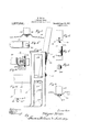
- FIG. 1 l shows a somewhatodiagramembodying my.
- Fig. 2 ma rear elevation of a seatframe and theadjacent seat backs, showino a per- SPECUVGHVlQW of myimproved ad ustable ;means for .attaching theseat backs to the plates are attached to the frames;
- Fig. 7 shows the rear elevation of the structure, illustrated in Fig. 6; I
- Fig. 8 shows a plan view of the clip or washerwhich engages the stud or bolt carried by the frame
- Fig. .9 shows a top; plan view of the lower connecting arms or plates secured to the chair frame;
- Fig. 10 shows a rear elevation of the chair frame with the connecting plates in position, and the clip and head of the bolt removed;
- V Fig. 11 is a top plan view of a portion of a chair frame, showing the stud engaged by a nut.
- FIG- 1 of the drawings I have shown three chairs, A, B,jand C, which are arranged in the arc of a circle, according to Each chair comprises a seat support 15 and a backsupport 16, which are mounted between the frame members 17, as shown in mounted upon the frames by means of ad- ;justable pivots or hinges 18, which enable the seats to be adjusted so as to be directed toward the commonv center and arranged members 17*, which are formed integrally V in level position.
- Many forms of adjustable joints or hinges 18 are known, and
- each chairframe comprises the parallel vertically extending with the transversely-extending members 17 and 17 Flanges 17 extend around the I and so as to properly aline with the seats 15.
- I preferably provide each of the rear members 17 of the chair frames with an arcuate surface 20, curved in a substantially horizontal plane, and engaging the chair frame normally to the arcuate surface 20 are the studs 21 having the enlarged heads 21 As shown in Figs. 1 and 2, one of the studs 21engages the chair frame adjacent the top thereof, and another stud is located at a lower intermediate point.
- the chair back 16 is mounted between a pair of chair frames 17 and has secured thereto,'at each side thereof, two connecting arms, or plates, 22 and 23.
- Each of the upper oppositely-disposed plates 22 is offset inwardly and twisted slightly, terminating in an arcuate portion 22*, preferably of slightly different curvature than the arcuate surface 20.
- the portion 22 of each of the upper plates is provided with an aperture 22 which is somewhat larger than the head 21 of the adjacent stud 21, so that the head 21- may be passed through the aperture 22,
- the lower plates 23, carried by each chair back, are twisted and ofiset outwardly from the plane of the chair back, as clearly shown in Fig. 9, and terminate in arcuate plates 23 which are preferably of slightly different curvature than the surface 20.
- These portions 23 of the plates 23 are similarly provided with apertures 23 slightly larger than the heads 21 of the studs, which apertures are adapted to be engaged by said heads when the arms are being passed into engagement with the studs. are ofl'set inwardly and the lower plates 23'
- the upper plates 22 are offset outwardly for the'purpose of giving to the chair backs the proper upward and rearward inclination, since it will be observed that the rear surfaces 20 of the chair frames are substantially vertical.
- curved clips or washers 2 Afterpassing the plates 22 and 23 of adj acent chair backs into engagement with the studs 21, carried by the intermediate chair frame, curved clips or washers 2 1, having transverse slots 3 2% formed therein, are passed over the studs 21 between the heads 21 thereof and the adjacent plates 22 and 23.
- the slots 25L are of such size that the walls thereof closely engage the stems of the studs 21 and the clips 24. are of such dimensions as to overlap the boundaries of the apertures 22 and 23", which are formed in the corresponding connecting plates. It will be seen that after the clips 24 are placed in position, the plates 22 and 23 will be secured against displacement from the studs 21.
- the studs may be fixed in the frames and threadedly engaged by nuts, as shown in Fig. 11, in which the threaded stud 21 is engaged by a nut 21.
- the plates 22 and 23 may be passed over the nuts, or if the apertures 22 and 23 are not large enough for that purpose, the nuts may be removed until after the plates are in place on the studs, after which the nuts are replaced. Then after adjusting the plateson the studs transversely to the axes thereof, the nuts may be tightened to clamp the parts in position.
- a nut is the equivalent of the head of a stud and that the usual bolt may be usedvif desired.
- the; apertures 22 and 23 are of'such size as to permit a considerable lateral adjustmentof the plates 22 and 23, toward or away from corresponding plates carried by adjacent chairs, so as to compensate for varying' rela tive inclinations of the adjacent chair frames 17.
- the limits of adjust'ability inay bevaried by varying the sizes of the apertures 22 and 23 It will be seen that by means of my im---" as the connections of the plates 22 and 23 to the chair backs.
- the chair backs may be hung on the studs 21, the clips 24 placed in position, and the plates 22 and 23 then adjusted on the studs so as to secure the proper alinement and adjustment of the chair backs to compensate for irregularities or variations in the level of the floor, and for curvatures and other irregularities in the rows of chairs.
- the studs 21, or the nuts thereon are tightened and the chair backs are securely fixed in position.
- What I claim is 1.
- a frame a chair back on each side of said frame, arms attached to each of said chair backs, said arms being apertured, and a bolt engaging both of said arms and said frame,
- said apertures being of larger size than the stem of said bolt.
- a frame In a device of the class described, a frame, a pair of supporting members located on opposite sides of said frame, a
- a pair of chair backs a chair frame between said chair backs, a stud projecting from said frame, an arm attached to each of said chair backs, and a slotted clip engaging said stud and overlapping said apertures.
- a pair of chair backs a chair frame between said chair backs, a pair of studs projecting from said frame, and arms secured to each of said chair backs, said arms being oppositely disposed in pairs, the arms of each pair being adapted to overlap and being apertured to engage one of said studs, said apertures being of larger size than the stems of said studs.
- a pair of chair backs a chair frame between said chair backs, a pair of studs projecting from said frame, and arms secured to each of said chair backs, said arms being oppositely disposed in pairs, the arms of each pair being adapted to overlap and being apertured to engage one of said studs, and slotted clips engaging said studs outwardly of said arms.
- a chair frame having an upward-extending surface curved substantially in a horizontal plane, a chair back on each side of said frame, a stud projecting from the curved surface of said frame, plates secured to said chair backs and having curved extremities of different curvatures than the curved surface of said frame with which they are adapted to coact, and a clip engaging said stud, whereby when said stud is tightened said plates will be clamped between said clip and said curved surface of the frame.
- a chair frame having an upwardly extending surface on the rear side thereof, a chair back on each side of said frame, a stud projecting from said surface of said frame, plates secured to said chair backs and having curved extremities adapted to coact With.
- a series of chair frames, lugs projecting from the rear Walls of said chair frames, chair Copies of this patent may be obtained for 11.
- a frame having a vertically extending surface curved substantially in a horizontal plane, a pair of chair backs located on opposite sides of said frame, arms attached to said chair backs and having curved extremities overlapping on said curved surface, and clamping means for securing said arms to said frame and permitting adjustment thereof on said curved surface.
Landscapes
- Health & Medical Sciences (AREA)
- Dentistry (AREA)
- General Health & Medical Sciences (AREA)
- Chairs For Special Purposes, Such As Reclining Chairs (AREA)
Description
W. WILLS.
ADJUSTABLE CHAIR. APPLICATION FILED AUG-30 1915.
Patented Aug. 21, 1917.
2 SHEETS-SHEET 1.
Ii; WM
W O 1: I! 1. l 1
N O O .7 .t 0 1 ILL 11 L M L. 1 HE flwmzzr,
W. WILLS.
ADJUSTABLE CHAIR.
APPLICATION man Aua.30. 1915.
Patented Aug. 21, 1917.
2 SHEEN-SHEET 2.
WAYNEWILLS, OF CHICAGO, ILLINOIS, ASSIGNOR T0 AMERIOAN'sEATING OOMBANY.
or CHICAGO, ILLINOISfJA CORPORATION OF NEW JERSEY.
ADJUSTABLE CHAIR.
Specification of Letters Patent. Patented Aug. 21,1917
; Application filed August 30, 1915.:-Seria1 1\To.-48,110.
To all whom it may concern:
Be it known that I, IVAYNEWVILLS, a citizen of the United States, residing-at Chicago, in the county of Cook and" State of Illinois, have invented certain new and useful Improvements in Adjustable Chairs, of
- matic topplan view of a series of chairs which the following is a specification.
This invention relates to chair construe-n t1on,.and.1n particular to an lmproved ad-,
justable chair adapted for use in theaters, auditoriums, or other places where large numbers of seats are arranged in series, and where the symmetry and convenience of the arrangement require that the supporting members of the chairs be adjustable with respect to their supports or frames, and with respect to each other. I
In many buildings, particularly in theaters, it is found that floors are inclined, or have present therein elevations, depressions, or othervariations in level, which cause a corresponding variation in the level:of the adjacent seat frames. Furthermore, where the chairs are arranged in arcs of circles, the frames of the chairs must be relatively inclined so as to be directed toward the center of the arc. These conditions require that the seats proper be adjustable with respect to the frames, and also that the back. sup: ports of the. chairs be adjustable laterally and vertically with respect to the frames, in
order that the seats propermay be directed may be inclined properly and arranged in a symmetrical arc.
The principal object of this invention is to provide improved adjustable means for vertically within the required limits to per-j 45.
connecting a supporting member of a chair to the frame thereof. By'meansof my invention the back support of the chair 1s attached to adjacent frame members in such the usual plan in theaters and the like.
manner as to be adjustable laterally and mit the desired adjustment and alinement of the adjacent chairs. Another Object of the invention is toprovide means whereby the supporting members, such as the baclrs of adjacent chairs, may be placed in pos1-- tion and supported by the frames, after which said members maybe adjusted later ally and verticallyas desired, and secured in fixed position.
. These and other objects: and features of the invention will be set orthrmore particularly.
in the following specification, taken in connection with the accompanying drawings, in which one. embodiment of thei-nvention is illustrated.
In the. drawings,
; Figure 1 l shows a somewhatodiagramembodying my. invention Fig. 2 ma rear elevation of a seatframe and theadjacent seat backs, showino a per- SPECUVGHVlQW of myimproved ad ustable ;means for .attaching theseat backs to the plates are attached to the frames;
Fig. 7 shows the rear elevation of the structure, illustrated in Fig. 6; I
, Fig. 8 shows a plan view of the clip or washerwhich engages the stud or bolt carried by the frame;
Fig. .9 shows a top; plan view of the lower connecting arms or plates secured to the chair frame;
Fig. 10 shows a rear elevation of the chair frame with the connecting plates in position, and the clip and head of the bolt removed; and
V Fig. 11 isa top plan view of a portion of a chair frame, showing the stud engaged by a nut.
. In Fig- 1 of the drawings I have shown three chairs, A, B,jand C, which are arranged in the arc of a circle, according to Each chair comprises a seat support 15 and a backsupport 16, which are mounted between the frame members 17, as shown in mounted upon the frames by means of ad- ;justable pivots or hinges 18, which enable the seats to be adjusted so as to be directed toward the commonv center and arranged members 17*, which are formed integrally V in level position. Many forms of adjustable joints or hinges 18 are known, and
this feature is therefore not described in detail.
It will be seen that each chairframe comprises the parallel vertically extending with the transversely-extending members 17 and 17 Flanges 17 extend around the I and so as to properly aline with the seats 15. For this purpose I preferably provide each of the rear members 17 of the chair frames with an arcuate surface 20, curved in a substantially horizontal plane, and engaging the chair frame normally to the arcuate surface 20 are the studs 21 having the enlarged heads 21 As shown in Figs. 1 and 2, one of the studs 21engages the chair frame adjacent the top thereof, and another stud is located at a lower intermediate point.
The chair back 16 is mounted between a pair of chair frames 17 and has secured thereto,'at each side thereof, two connecting arms, or plates, 22 and 23. Each of the upper oppositely-disposed plates 22 is offset inwardly and twisted slightly, terminating in an arcuate portion 22*, preferably of slightly different curvature than the arcuate surface 20. The portion 22 of each of the upper plates is provided with an aperture 22 which is somewhat larger than the head 21 of the adjacent stud 21, so that the head 21- may be passed through the aperture 22,
when the arm 22 will be supported in position resting upon the stud 21.
The lower plates 23, carried by each chair back, are twisted and ofiset outwardly from the plane of the chair back, as clearly shown in Fig. 9, and terminate in arcuate plates 23 which are preferably of slightly different curvature than the surface 20. These portions 23 of the plates 23 are similarly provided with apertures 23 slightly larger than the heads 21 of the studs, which apertures are adapted to be engaged by said heads when the arms are being passed into engagement with the studs. are ofl'set inwardly and the lower plates 23' The upper plates 22 are offset outwardly for the'purpose of giving to the chair backs the proper upward and rearward inclination, since it will be observed that the rear surfaces 20 of the chair frames are substantially vertical. I
Where the rear surfaces 20 of the hai'r frames are inclined upwardly and rearwardly at the desired angle, it may be unnecessary to offset the plates 22 and 23 in the manner above described, in order to secure the proper inclination of the chair backs.
Afterpassing the plates 22 and 23 of adj acent chair backs into engagement with the studs 21, carried by the intermediate chair frame, curved clips or washers 2 1, having transverse slots 3 2% formed therein, are passed over the studs 21 between the heads 21 thereof and the adjacent plates 22 and 23. The slots 25L are of such size that the walls thereof closely engage the stems of the studs 21 and the clips 24. are of such dimensions as to overlap the boundaries of the apertures 22 and 23", which are formed in the corresponding connecting plates. It will be seen that after the clips 24 are placed in position, the plates 22 and 23 will be secured against displacement from the studs 21. The enlarged apertures 22? and 23 will, however, permit a considerable lateral and vertical adjustment of the plates22 and 23 with respect to the chair frame 17, and as this adjustment takes place the portions 22 and 23 of the plates will slide upon the arcuate surfaces 20. After the plates 22 and 23 have been adjusted with respect to the studs21, so that the chair backs 16 are in the desired alinement with each other, and with the seats 15, the studs 21 may be passed into tighter engagement with the chair frames 17, so as to tightly clamp the clips 24L against the plates 22 and 23, and thereby secure the latter in fixed position.
It will be observed that by varying the radii of the various coacting arcuate surfaces, a spring-like resistance. is set up against the tightened studs, resulting in the effect of locking the studs against turning or loosening because of vibration or the like.
Instead of tapping the studs 21 into the chair frames, as illustrated in Fig. 6, or into the oppositely-disposed nuts, the studs may be fixed in the frames and threadedly engaged by nuts, as shown in Fig. 11, in which the threaded stud 21 is engaged by a nut 21. With this construction the plates 22 and 23 may be passed over the nuts, or if the apertures 22 and 23 are not large enough for that purpose, the nuts may be removed until after the plates are in place on the studs, after which the nuts are replaced. Then after adjusting the plateson the studs transversely to the axes thereof, the nuts may be tightened to clamp the parts in position. In the interpretation of'the appended claims, it will be understood that a nut is the equivalent of the head of a stud and that the usual bolt may be usedvif desired.
In Fig. 2 of the drawings, it will be seen that the plates 22, carried by the right-hand chair back, have a'more elevated*positionr with respect to the studs21 than? the-corresponding platescarried byjthe left-hand chair, which maybe necessary, for instance,
when the chair frame at the other ,side of so as to show the limits of this adjustment more clearly. It will be understood that the; apertures 22 and 23 are of'such size as to permit a considerable lateral adjustmentof the plates 22 and 23, toward or away from corresponding plates carried by adjacent chairs, so as to compensate for varying' rela tive inclinations of the adjacent chair frames 17. The limits of adjust'ability inay bevaried by varying the sizes of the apertures 22 and 23 It will be seen that by means of my im---" as the connections of the plates 22 and 23 to the chair backs. After the chair frames have been secured to the floor, which is usually of cement construction, the chair backs may be hung on the studs 21, the clips 24 placed in position, and the plates 22 and 23 then adjusted on the studs so as to secure the proper alinement and adjustment of the chair backs to compensate for irregularities or variations in the level of the floor, and for curvatures and other irregularities in the rows of chairs. After this has been done, the studs 21, or the nuts thereon, are tightened and the chair backs are securely fixed in position.
Although I have shown and described a articular embodiment of the invention and have explained its operation in a particular manner for purposes of illustration, it will be understood that the invention may be embodied in various other forms without departing from the scope thereof, as defined in the appended claims.
What I claim is 1. In a device of the class described, a frame, a chair back on each side of said frame, arms attached to each of said chair backs, said arms being apertured, and a bolt engaging both of said arms and said frame,
said apertures being of larger size than the stem of said bolt.
2. In a device of the class described, a frame, a pair of supporting members located on opposite sides of said frame, a
stud engaging said frame, arms attached to each of said supporting members, the over lapping ends of said arms being apertured to pass over the head of said stud and to permit adjustment transversely to the axis of said-sstud, and a clipxengagingsaid stud to prevent displacement 'of-said arms.
' 3. Ina device'ofthe class described, a
frame having a vertically-extending sursurfaceof saidiframe, the extremity of said face curved substantially in a horizontal plane, a stud engagi'ngsaid frame normally to said surface, a chair back, a plate secured to said chair-back and having a curved extremity adapted to coact with'th'e curvedplatebeingapertured to receive the enlarged head- 0f said stud, whereby said plate may be pa'ssedinto engagement therewith, and
a clip'adap'ted to'fit'over said stu'd'and pre-- vent-displacement of said plate.
4:. In a device of the class described, a
pair of chair backs, a chair frame between said chair backs, a stud projecting from saidframe, an arm attached to each of said chair backs, said arms being apertured to be engaged by said stud, and a clip engaging said stud.
5. In a device of the class described, a pair of chair backs, a chair frame between said chair backs, a stud projecting from said frame, an arm attached to each of said chair backs, and a slotted clip engaging said stud and overlapping said apertures.
6. In a device of the class described, a pair of chair backs, a chair frame between said chair backs, a pair of studs projecting from said frame, and arms secured to each of said chair backs, said arms being oppositely disposed in pairs, the arms of each pair being adapted to overlap and being apertured to engage one of said studs, said apertures being of larger size than the stems of said studs.
7 In a device of the class described, a pair of chair backs, a chair frame between said chair backs, a pair of studs projecting from said frame, and arms secured to each of said chair backs, said arms being oppositely disposed in pairs, the arms of each pair being adapted to overlap and being apertured to engage one of said studs, and slotted clips engaging said studs outwardly of said arms.
8. In a device of the class described, a chair frame having an upward-extending surface curved substantially in a horizontal plane, a chair back on each side of said frame, a stud projecting from the curved surface of said frame, plates secured to said chair backs and having curved extremities of different curvatures than the curved surface of said frame with which they are adapted to coact, and a clip engaging said stud, whereby when said stud is tightened said plates will be clamped between said clip and said curved surface of the frame.
9. In a device of the class described, a chair frame having an upwardly extending surface on the rear side thereof, a chair back on each side of said frame, a stud projecting from said surface of said frame, plates secured to said chair backs and having curved extremities adapted to coact With.
said surface of said frame, and a clip engaging said stud, whereby the tightening of said stud Will clamp said plates on said surface of the frame.
10. Ina device of the class described, a series of chair frames, lugs projecting from the rear Walls of said chair frames, chair Copies of this patent may be obtained for 11. In a device of the class described, a frame having a vertically extending surface curved substantially in a horizontal plane, a pair of chair backs located on opposite sides of said frame, arms attached to said chair backs and having curved extremities overlapping on said curved surface, and clamping means for securing said arms to said frame and permitting adjustment thereof on said curved surface.
In testimony whereof, I have subscribed my name.
WAYNE WILLS Witnesses: i
C. B. STILLWELL, G. H. LEUTHSTROM.
five cents each, by addressing the Commissioner of Patents Washington, D. G.
Priority Applications (1)
| Application Number | Priority Date | Filing Date | Title |
|---|---|---|---|
| US4811015A US1237850A (en) | 1915-08-30 | 1915-08-30 | Adjustable chair. |
Applications Claiming Priority (1)
| Application Number | Priority Date | Filing Date | Title |
|---|---|---|---|
| US4811015A US1237850A (en) | 1915-08-30 | 1915-08-30 | Adjustable chair. |
Publications (1)
| Publication Number | Publication Date |
|---|---|
| US1237850A true US1237850A (en) | 1917-08-21 |
Family
ID=3305667
Family Applications (1)
| Application Number | Title | Priority Date | Filing Date |
|---|---|---|---|
| US4811015A Expired - Lifetime US1237850A (en) | 1915-08-30 | 1915-08-30 | Adjustable chair. |
Country Status (1)
| Country | Link |
|---|---|
| US (1) | US1237850A (en) |
Cited By (4)
| Publication number | Priority date | Publication date | Assignee | Title |
|---|---|---|---|---|
| US3077364A (en) * | 1959-09-28 | 1963-02-12 | California Church Furniture Co | Stadium seating structure |
| US3347593A (en) * | 1966-04-18 | 1967-10-17 | Cramer Ind Inc | Spectator seating structure |
| US3531157A (en) * | 1968-08-23 | 1970-09-29 | Composite Structures Inc | Seat construction |
| US3541742A (en) * | 1968-08-07 | 1970-11-24 | Charles H Harper | Theater seating |
-
1915
- 1915-08-30 US US4811015A patent/US1237850A/en not_active Expired - Lifetime
Cited By (4)
| Publication number | Priority date | Publication date | Assignee | Title |
|---|---|---|---|---|
| US3077364A (en) * | 1959-09-28 | 1963-02-12 | California Church Furniture Co | Stadium seating structure |
| US3347593A (en) * | 1966-04-18 | 1967-10-17 | Cramer Ind Inc | Spectator seating structure |
| US3541742A (en) * | 1968-08-07 | 1970-11-24 | Charles H Harper | Theater seating |
| US3531157A (en) * | 1968-08-23 | 1970-09-29 | Composite Structures Inc | Seat construction |
Similar Documents
| Publication | Publication Date | Title |
|---|---|---|
| US575631A (en) | brooks | |
| US11633046B2 (en) | Sectional seating system | |
| US1237850A (en) | Adjustable chair. | |
| US1322551A (en) | Best attachment fob babbeb-chaibs | |
| US1326363A (en) | Support. | |
| US605527A (en) | Robert e | |
| US1297718A (en) | Rocking-chair. | |
| US549466A (en) | Benjamin s | |
| US786326A (en) | Spring-back for chairs. | |
| US2331060A (en) | Seat or chair securing means | |
| US1063566A (en) | Pipe hanger or support. | |
| US242633A (en) | gueeeant and petee m | |
| US535783A (en) | Head-rest | |
| US557406A (en) | linn x | |
| US402709A (en) | Camp-stool | |
| US153547A (en) | Improvement in spring-chairs | |
| US931821A (en) | Opera-chair. | |
| US144020A (en) | Improvement in springs for chairs | |
| US859913A (en) | Fan attachment. | |
| US2231654A (en) | Bicycle seat | |
| US664158A (en) | Spring-seat for chairs, sofas, wagon-seats, &c. | |
| JP3219730U (en) | Hanging chair | |
| US2895540A (en) | Combined chair arm and connector | |
| US1225776A (en) | Spine rest or support. | |
| US333393A (en) | Chair |