US1237641A - Combined type-writing and computing machine. - Google Patents
Combined type-writing and computing machine. Download PDFInfo
- Publication number
- US1237641A US1237641A US64111711A US1911641117A US1237641A US 1237641 A US1237641 A US 1237641A US 64111711 A US64111711 A US 64111711A US 1911641117 A US1911641117 A US 1911641117A US 1237641 A US1237641 A US 1237641A
- Authority
- US
- United States
- Prior art keywords
- carriage
- shaft
- computing
- rock
- tappet
- Prior art date
- Legal status (The legal status is an assumption and is not a legal conclusion. Google has not performed a legal analysis and makes no representation as to the accuracy of the status listed.)
- Expired - Lifetime
Links
Images

Classifications
-
- G—PHYSICS
- G06—COMPUTING OR CALCULATING; COUNTING
- G06C—DIGITAL COMPUTERS IN WHICH ALL THE COMPUTATION IS EFFECTED MECHANICALLY
- G06C21/00—Programming-mechanisms for determining the steps to be performed by the computing machine, e.g. when a key or certain keys are depressed
- G06C21/04—Conditional arrangements for controlling subsequent operating functions, e.g. control arrangement triggered by a function key and depending on the condition of the register
Definitions
- One of the principal objects of the present improvements is to provide means for effecting an improved, intermittent automatic connection between the motor and the general operator of the adding machine.
- a stop or margin gage is provided upon the typewriter for arresting the carriage at its return movement, and just as the carriage con cludes such return movement, the general operator of the adding machine is operated by the motor. Provision is made for adjustment of the width of margin on the left hand side of the work sheet, and the automatic operation of said general operator is caused to occur always at the conclusion of the return stroke of the carriage, regardless of the length of such return stroke.
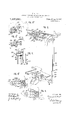
- Figure 1 is a part sectional side elevation of an Underwood-Hanson combined typewriting and adding machine, embodying the present improvements.
- Fig. 2 is a sectional view of the clutch employed between the electric motor and the general operator of the adding machine.
- Fig. 3 is a perspective front view of the carriage-controlling mechanism.
- FIG. 3 is a sectional rear elevation of the carriage projection and the tappet engaged thereby, F1 -Bfflis a view similar to Fig. 3, showmg t e c'arriage as moving in letter-feeding direction, as shown by the arrow, independently of said tappet.
- Fig. 4 is a plan of the adjustable margin gage with the clutch-operating tappet coupled thereto.
- Fig. 4? is a sectional side elevation illustrating the depression of the tappet and rocking of the shaft by means of the projection on the carriage.
- Fig. 5 is a view similar to Fig. 4, but showing the parts in the normal positions.
- a continuously running electric or other motor 1 is provided with a main shaft 2, the latter connected to a shaft 3 by means of a safety friction clutch, not shown.
- a rack 13, forming part of a rack frame or general operator, is movable forwardly and backwardly in the base of the adding machine, and performs the final portion of the computing operation.
- This rack frame is reciprocated intermittently by the constantly rotating shaft 3, by means of a clutch mechanism; said rack frame being connected to a crank shaft to be driven thereby, and the crank shaft being connected by a worm gearing to said shaft 3, as will presently be set forth.
- a yoke or carrier 14 Upon the rack frame is secured a yoke or carrier 14, in engagement with which is the upper end of an arm 15, provided on a cross head 16, which moves forwardly and backwardly, or from left to right at Fig. 1,
- sa1d cross head being carried on a horizontal slide 17, which works in bearings 18 on a casing 19.
- This slide is reciprocated by means of a crank 23, fixed on a horizontal shaft 24; said crank carrying a slide block 26, working in a groove 27 in the cross head.
- Loose on shaft 24 is a worm gear 30, meshing with a worm 31, the latter fixed on shaft 3, so that the worm wheel 30 is constantly rotating.
- the worm wheel 30 is connectible to shaft 24 to turn the same whenever it is necessary to reciprocate the rack frame 13 to complete a computing operation; and at the conclusion of said reciprocation, said worm wheel 30 is automatically disconnected from the shaft 24, and the latter comes to a stop,
- a cup member 32 of a clutch Fixed to the shaft 24 is a cup member 32 of a clutch; and fixed to the hub of worm gear 30 is a collar 33.
- a gripping ball or roll 34 Running on this 001- lar and adapted to engage the inside of a cylindrical face of the clutch cup 32, is a gripping ball or roll 34; said roll occupying a pocket 35 in the clutch cup, and rolling on an inclinedfloor 35 thereof, so that relative movement of the clutch cup and collar 33 in one direction will cause said members to be clutched together by the roll, while relative movement in the opposite direction will produce the opposite effect, so as to permit independent rotation of the gear 30.
- the clutch roll is shiftable between gripping and releasing positions in the pocket 35 by means of a dlsk or ring 36, which rides loosely on the collar 33 within cup 32, and which is cut away at one place to receive the roll 34 so as to engage the roll on both sides thereo Rotation of rin 36, therefore, shifts the roll.
- a compression s ring 38 which is confined within a pocket 3 formed in said disk; the other end of said spring bearing a ainst a stop 39 secured to the inner side of the clutch cup.
- the pocket 37 is of sufficient length to permit a movement of the disk or ring 36 without interference from the stop 39.
- the spring tends to turn the disk 36 with the roll 34 in adirection to lock together the clutch cup with the bearing collar to cause shaft 24 to rotate with gear 30. In other words, said spring tends normally to close the clutch. Normally, however, said disk 36 is restrained from causing the roll to bind; or in other words, said disk is normally held in clutch-releasing position.
- a trip pin or latch 40 normally in engagement with a lug 41 provided upon releasing disk 36, said lug projecting through an opening in the clutch cup.
- the latch 40 is raised to release lug 41, whereupon spring 38 throws disk 36, together with roll 34, thus locking the clutch cup and the shaft 24 to the rotating worm gear 30.
- the pin 40 is automatica y dropped again into the path of lug 41, so that at the completion of a single rotation of the shaft 24, the latter is again unclutched from the Worm gear 30.
- the rack frame 13 is caused to reciprocate after the numeral keys of the typewriter have been operated to set up a number. This rack frame operates to turn the computing wheels to different extents, depending upon the key operated.
- lever 44 pivoted at its lower end to a lever 44, fulcrumed at 45 upon the machine framej Said lever 44, in turn, de resses a cross lever 46, which is pivoted at 4 to the framework, and at its other end engages a notch 48 formed in the top of the trip pin or latch 40, so as to cause or control the up and down move ment of'said latch, whereby the clutch is caused to close and open.
- the lever 46 is provided with an adjustable end or arm 50, upon which the key lever 42 bears; this part 50 being adjustable b screws 52, thereby securing accuracy 0 adjustment and movement of the clutch-controlling mechanism.
- depression of the key 42 carries down the lever 44, the latter'rocks the lever 46 about its fulcrum 45, the other end of the lever lifting; the latch 40 away from the clutch lug 41.
- the typist immediately releases the key 42, which is returned to normal position by a spring 54.
- the movement of the key 1s limited by a pin 55 within a slot 56 in the key stem.
- the lever 46 has a returning spring 57.
- the typewriter includes the usual Set of type-operating keys, including alphabet keys and also including numeral keys 88 mounted on lever 88 and connected by bell cranks 89 to type bars 90, which are thrown back against a platen 91 mounted on a carriage 92.
- the carriage is power-driven, as usual, and has a rack 87 meshing with a pinion 86, connected with an escapement wheel 85, the latter controlled by dogs 84, operated by a universal bar 83, which is actuated by the type bars, so that whenever any t pe key is actuated, the carriage 92 is cause to feed a letter space.
- brackets 93 Fastened at the back of the carriage 92, are brackets 93, carrying a rack 94, to receive adjustable cams or tappets 95.
- any tappet during the travel of the carriage, passes beneath the set of jacks 96, it raises the forward ends of the jacks in succession, turning each-on its pivot 97, and depressin its rear end to press down the correspon ing one of a set of wires 98.
- These wires are connected at their lower ends to levers 9 on a fulcrum rod 100.
- Each lever 99 raises one of a set of linkages 101, each linkage havinga pin 102 to lift the rear end'of a rack 103, the forward end of which meshes with a pinion 104 connected to a computing wheel-.105.
- Each rack carries a set of pins 106, and one of these is depressed by the operated type key 88; each keyhaving a stem 110, for this purpose, to depress a crank 112, fast to a shaft 113, which is connected to a linkage 114, to depress oneof the pins 106 upon the lifted rack bar 103; there being one linkage 114 for each key, each linkage being in po sition to depress a corresponding pin 106 on whichever rack bar is lifted, as set forth in my pending applications.
- This frame usually includes a pair of arms 115 connected' by a transverse horizontal bar 116, which is in position to, engage all the displaced pins 106, and to give corresponding forward endwise movements to their racks 103, thereby turning the com uting wheels 105 accordingly; the return movements of the racks not turning said wheels, however, because of a pawl-and-ratchet connection l (not shown) between said wheels and their drive pinions 104.
- Pinions 116 meshing with racks 13, are also in mesh with segments 116 fixed on rock-shaft 116.
- a projection 120 which on the Underwood typewriting machine, forms part of the line-locking mechanism, and which in the present instance is utilized during the return movement of the carriage for effecting or controlling the operation of the general operator 13, 116, etc.
- This projection 120 has at its right hand end a bevel portion or cam face 121, which at the completion of the return stroke of the carriage, engages a bevel 122 formed on a tappet 123, for which there is provided a mount in the form of a block 124, the latter splined by a key 125 to-a rock shaft 126 which is mountedforwardly of the front carriage rail 127 upon which runs the front carriage roll 128.
- This operation of the carniage occurs just as the latter finishes its return stroke; such stroke being limited by a stop 133 usually provided on the carriage, and a counterstop 134, carried on the rail 127 and forming part of the usual gage to regulate the width of the margin on the left hand side of" the work sheet.
- Said counter-stop 134 is usually provided upon a gage 135 having a dog 136 pivoted thereon at 137, and having teeth 138 to engage rack-teeth 139 out on the front side of the rail 127.
- Said dog has a finger piece 140 in proximity to a finger piece 141 provided upon the margin gage 135, so that by pressing said finger pieces toward each other, the dog is released,
- the margin gage may be ad usted along the rods 126 and 127 to any desired point, and then the fingerpieces may be released, whereupon a spring 142 returns said dog into mesh with the rack 139, thereby securing the margin gage where set.
- the mount 124 which carries the tappet 123 is connected by an accompanying finger releasing lever 144, whereby it may be lifted.
- said cam 120 or 121 upon engaging the tappet 123, causes the latter to sink, as seen at Fig. 3", said tappet for this purpose being pivotally mounted at 145 upon the mount 124; a weak spring 146 returning the tappet to normal position after the cam or projection 120 passes the same.
- the projection 121 after forcing down the tappet 123, passes a trifle beyond the latter, so that it may swing up again by reason of the tension of spring 57, so that the trip pin 40 may return instantly to normal position.
- the link 130 may have a vertical slot 147 to engage guide screws 148, and the bar 132 may have a similar slot 149 and guide screw 150.
- the link 130 will lift off from the bar 132, so that no difficulty is experienced in separating the typewriter frame from the adding machine frame.
- the margin gage 135 is provided with a usual pointer 153 to cooperate with the usual scale.
- a typewriting and computing machine the combination with a typewriter carriage, type-operating numeral keys, aletter-feeding mechanism for said carriage operable by said keys, computing devices associated with said carriage, means set by said keys for determining the extent of operation of the computing devices, and an o erator for moving the computing devices, 0 means connected to a source of power for actuating said operator, a margin stop for said carriage and means connected to said stop and operable by the typewriter carriage at its return stroke, for controlling the operation of said actuating means.
- a typewriting and computing machine the combination with a typewriter carriage, type-operating numeral keys, a letter-feeding mechanism for said carriage operable by said keys, a margin stop for said carriage forming part of the typewriting mechanism, computing devices associated with said carriage, means set by said keys for determining the extent of operation of the computing devices, and an operator for moving the computing devices, of a rotary actuator connected to said operator for reciprocating the same, a rotating motor, a normally open clutch between said rotary actuator and said motor, and means connected in driving relation to said stop of the typewriting mechanism for controlling the closing of said clutch automatically upon the return movement of the carriage to begin a new line of writing.
- a typewriting and computing machine the combination with a typewriter carriage, type-operating numeral keys, a letter-feeding mechanism for said carriage operable by said keys, a margin stop for said carriage computing devices assoclated with said carriage, means set by said keys for determining the extent of operation of the computing devices, and an operator for mov ing the computing devices, of a rotating motor, a rotary device connected to said operator for reciprocating the same, a normally open clutch between said rotary device and said motor, said clutch tending constantly to close, a device to restrain said clutch from closing, and means connected in driving relation to said margin stop and dependent upon a return movement of the typewriter carriage for releasing said clutch from the control of said restraining device.
- a typewriting mechanism including a carriage, of carriage-feeding numeral keys, computing devices settable by said keys, a general operator for said computing devices, a constantly running motor for actuating said general operator but normally disconnected therefrom, a tappet, a projection on said carriage to engage said tappet during a movement of said carriage, a rock shaft supporting said tappet to enable said carriage to rock said shaft, said typewriting mechanism being dismountable, and an inlimit of a typewritten line, of a computing mechanism for calculating numbers written by said typewriting mechanism, means to operate said computing mechanism, a motor, and means to enable said gage to control the driving of said operating meansby said motor.
- a typewriting mechanism including a traveling carriage and type actions cooperating to effect the writing of a line
- a computing mechanism cooperating with said typewriting mechanism to calculate numbers written by said typewriting mechanism in a line
- said computin mechanism including a general operator or running up the numbers to be computed, and means for simultaneously adjusting the travel of said carriage and the oint of operation of said general operator 1n the travel of said carriage.
- said typewriting mechanism operating with said typewriting mechanism to calculate numbers written in a line, said computing mechanism including a general operator for running up the numbers computed, and 006 eratmg means on said carrlage and sai margin gage connected to operator at one end of a written line.
- an operator for moving the computing devices of an actuator connected to said operator for reciprocating the same, a rotating motor, a normally open clutch between said actuator and said motor, mechanically operating means connected'to said stop for closing said clutch upon the return movement of the carriage and by power applied to the 70 automatically bring into play said general carriage, said closing means including a part first actuated and then released by the carriage at the conclusion of the return stroke thereof, and means for restoring said clutch to normal open condition upon the completion of the movement of said operator.
Landscapes
- Physics & Mathematics (AREA)
- Engineering & Computer Science (AREA)
- Mathematical Physics (AREA)
- Computer Hardware Design (AREA)
- Computing Systems (AREA)
- General Physics & Mathematics (AREA)
- Theoretical Computer Science (AREA)
- Transmission Devices (AREA)
Description
F. A. HART.
COMBINED TYPE WRITING AND COMPUTING MACHINE.
APPLICATION FILED JULY 28, I91].
Patented Aug. 21, 1917.
2 SHEETS-*SHEET 1- FIG.
INVENTORI BY I ATTORNE SSES: M
WITNE 3".
F. A .HART.
I COMBINED TYPE WRITING AND COMPUTING MACHINE.
APPLICATION FILED JULY 28, I911 IN VENTOR:
ATTORNE W 0 7 fi H M Y M? B 6.? 4,6 0 a7 a M a" w u u I r m m in: Fv
7 o 3 6 wk a m fi 7" H a m WQw I B mm a 1| "0 1 6 E a 4/, WW M Pm S 3 S J// .r 0 W N 7 7 I 3 W1 UNITED STATES PATENT OFFICE.
FREDERICK A. HART, OF JERSEY CITY, NEW JERSEY, ASSIGNOR TO UNDERWOODCOH- PU'IIN G MACHINE COMPANY, OF NEW YORK, N. Y., A CORPORATION OF NEW YORK.
COMBINED TYPE-WRITING AND COMPUTING MACHINE.
To all whom it may concern:
Be it known that I, FREDERICK A. HART,
a citizen of the United States, residing in Jersey City, in the county of Hudson and State of New Jersey, have invented certain operated key.
One of the principal objects of the present improvements is to provide means for effecting an improved, intermittent automatic connection between the motor and the general operator of the adding machine.
To this end, I have contrived to cause the carriage of the typewriter, when it is being returned to'begin a new line of writing, to effect the desired connection. A stop or margin gage is provided upon the typewriter for arresting the carriage at its return movement, and just as the carriage con cludes such return movement, the general operator of the adding machine is operated by the motor. Provision is made for adjustment of the width of margin on the left hand side of the work sheet, and the automatic operation of said general operator is caused to occur always at the conclusion of the return stroke of the carriage, regardless of the length of such return stroke. To the gage which regulates such margin, I connect a tappet or device which is engaged by a projection on the carriage and causes a clutch to operate between the electric motor and the general operator; the clutch being automatically silenced at the conclusion of the operation of the general operator. Provision is also made whereby the carriage may move to any extent in letter-feeding direction independently of the clutch-controlling mechanism, so that when desired, the carriage may be moved to the right far enough to permit writing in the margin on the work sheet, whereupon the carriage Specification of Letters Patent.
Application filed. July 28, 1911.
Patented Aug. 21, 1917.
Serial No. 641,117.
may move in letter-feeding direction without effecting the operation of said clutch.
Other features and advantages will hereinafter appear.
In the accompanying drawings,
Figure 1 is a part sectional side elevation of an Underwood-Hanson combined typewriting and adding machine, embodying the present improvements.
Fig. 2 is a sectional view of the clutch employed between the electric motor and the general operator of the adding machine.
Fig. 3 is a perspective front view of the carriage-controlling mechanism.
3 is a sectional rear elevation of the carriage projection and the tappet engaged thereby, F1 -Bfflis a view similar to Fig. 3, showmg t e c'arriage as moving in letter-feeding direction, as shown by the arrow, independently of said tappet.
Fig. 4 is a plan of the adjustable margin gage with the clutch-operating tappet coupled thereto.
Fig. 4? is a sectional side elevation illustrating the depression of the tappet and rocking of the shaft by means of the projection on the carriage.
Fig. 5 is a view similar to Fig. 4, but showing the parts in the normal positions.
A continuously running electric or other motor 1 is provided with a main shaft 2, the latter connected to a shaft 3 by means of a safety friction clutch, not shown.
A rack 13, forming part of a rack frame or general operator, is movable forwardly and backwardly in the base of the adding machine, and performs the final portion of the computing operation. This rack frame is reciprocated intermittently by the constantly rotating shaft 3, by means of a clutch mechanism; said rack frame being connected to a crank shaft to be driven thereby, and the crank shaft being connected by a worm gearing to said shaft 3, as will presently be set forth.
Upon the rack frame is secured a yoke or carrier 14, in engagement with which is the upper end of an arm 15, provided on a cross head 16, which moves forwardly and backwardly, or from left to right at Fig. 1,
so as to reciprocate said rack frame 13; sa1d cross head being carried on a horizontal slide 17, which works in bearings 18 on a casing 19. This slide is reciprocated by means of a crank 23, fixed on a horizontal shaft 24; said crank carrying a slide block 26, working in a groove 27 in the cross head.
Loose on shaft 24 is a worm gear 30, meshing with a worm 31, the latter fixed on shaft 3, so that the worm wheel 30 is constantly rotating.
The worm wheel 30 is connectible to shaft 24 to turn the same whenever it is necessary to reciprocate the rack frame 13 to complete a computing operation; and at the conclusion of said reciprocation, said worm wheel 30 is automatically disconnected from the shaft 24, and the latter comes to a stop,
while the motor 1 continues to rotate.
Fixed to the shaft 24 is a cup member 32 of a clutch; and fixed to the hub of worm gear 30 is a collar 33. Running on this 001- lar and adapted to engage the inside of a cylindrical face of the clutch cup 32, is a gripping ball or roll 34; said roll occupying a pocket 35 in the clutch cup, and rolling on an inclinedfloor 35 thereof, so that relative movement of the clutch cup and collar 33 in one direction will cause said members to be clutched together by the roll, while relative movement in the opposite direction will produce the opposite effect, so as to permit independent rotation of the gear 30.
The clutch roll is shiftable between gripping and releasing positions in the pocket 35 by means of a dlsk or ring 36, which rides loosely on the collar 33 within cup 32, and which is cut away at one place to receive the roll 34 so as to engage the roll on both sides thereo Rotation of rin 36, therefore, shifts the roll. Against said disk 36 bears one end of a compression s ring 38, which is confined within a pocket 3 formed in said disk; the other end of said spring bearing a ainst a stop 39 secured to the inner side of the clutch cup. The pocket 37 is of sufficient length to permit a movement of the disk or ring 36 without interference from the stop 39. The spring tends to turn the disk 36 with the roll 34 in adirection to lock together the clutch cup with the bearing collar to cause shaft 24 to rotate with gear 30. In other words, said spring tends normally to close the clutch. Normally, however, said disk 36 is restrained from causing the roll to bind; or in other words, said disk is normally held in clutch-releasing position.
For this purpose, there is provided a trip pin or latch 40, normally in engagement with a lug 41 provided upon releasing disk 36, said lug projecting through an opening in the clutch cup. When shaft 24 is to be clutched to the gear 30, the latch 40 is raised to release lug 41, whereupon spring 38 throws disk 36, together with roll 34, thus locking the clutch cup and the shaft 24 to the rotating worm gear 30. The pin 40 is automatica y dropped again into the path of lug 41, so that at the completion of a single rotation of the shaft 24, the latter is again unclutched from the Worm gear 30.
The rack frame 13 is caused to reciprocate after the numeral keys of the typewriter have been operated to set up a number. This rack frame operates to turn the computing wheels to different extents, depending upon the key operated.
I will first describe means whereby the typist may depress a special key to operate said clutch, and cause the reciprocation of the rack frame or general operator; this mechanism being substantially shown in my application No. 596,451. Said key is designated as 42, and is mounted on a stem 43,
pivoted at its lower end to a lever 44, fulcrumed at 45 upon the machine framej Said lever 44, in turn, de resses a cross lever 46, which is pivoted at 4 to the framework, and at its other end engages a notch 48 formed in the top of the trip pin or latch 40, so as to cause or control the up and down move ment of'said latch, whereby the clutch is caused to close and open. The lever 46 is provided with an adjustable end or arm 50, upon which the key lever 42 bears; this part 50 being adjustable b screws 52, thereby securing accuracy 0 adjustment and movement of the clutch-controlling mechanism.
Depression of the key 42 carries down the lever 44, the latter'rocks the lever 46 about its fulcrum 45, the other end of the lever lifting; the latch 40 away from the clutch lug 41. The typist immediately releases the key 42, which is returned to normal position by a spring 54. The movement of the key 1s limited by a pin 55 within a slot 56 in the key stem. The lever 46 has a returning spring 57.
The typewriter includes the usual Set of type-operating keys, including alphabet keys and also including numeral keys 88 mounted on lever 88 and connected by bell cranks 89 to type bars 90, which are thrown back against a platen 91 mounted on a carriage 92. The carriage is power-driven, as usual, and has a rack 87 meshing with a pinion 86, connected with an escapement wheel 85, the latter controlled by dogs 84, operated by a universal bar 83, which is actuated by the type bars, so that whenever any t pe key is actuated, the carriage 92 is cause to feed a letter space. Fastened at the back of the carriage 92, are brackets 93, carrying a rack 94, to receive adjustable cams or tappets 95. Whenever any tappet, during the travel of the carriage, passes beneath the set of jacks 96, it raises the forward ends of the jacks in succession, turning each-on its pivot 97, and depressin its rear end to press down the correspon ing one of a set of wires 98. These wires are connected at their lower ends to levers 9 on a fulcrum rod 100.
Each lever 99 raises one of a set of linkages 101, each linkage havinga pin 102 to lift the rear end'of a rack 103, the forward end of which meshes with a pinion 104 connected to a computing wheel-.105. Each rack carries a set of pins 106, and one of these is depressed by the operated type key 88; each keyhaving a stem 110, for this purpose, to depress a crank 112, fast to a shaft 113, which is connected to a linkage 114, to depress oneof the pins 106 upon the lifted rack bar 103; there being one linkage 114 for each key, each linkage being in po sition to depress a corresponding pin 106 on whichever rack bar is lifted, as set forth in my pending applications. After the keys 88 are manipulated to write avnumber, and the corresponding racks 103 accordingly elev'ated as the paper-carriage feeds along, and certain pins 106 thereon depressed, there must be caused a reciprocation of the rack frame or general operator 13. This frame usually includes a pair of arms 115 connected' by a transverse horizontal bar 116, which is in position to, engage all the displaced pins 106, and to give corresponding forward endwise movements to their racks 103, thereby turning the com uting wheels 105 accordingly; the return movements of the racks not turning said wheels, however, because of a pawl-and-ratchet connection l (not shown) between said wheels and their drive pinions 104. Pinions 116 meshing with racks 13, are also in mesh with segments 116 fixed on rock-shaft 116.
Upon the front of the typewriter carriage 92 is fixed a projection 120, which on the Underwood typewriting machine, forms part of the line-locking mechanism, and which in the present instance is utilized during the return movement of the carriage for effecting or controlling the operation of the general operator 13, 116, etc. This projection 120 has at its right hand end a bevel portion or cam face 121, which at the completion of the return stroke of the carriage, engages a bevel 122 formed on a tappet 123, for which there is provided a mount in the form of a block 124, the latter splined by a key 125 to-a rock shaft 126 which is mountedforwardly of the front carriage rail 127 upon which runs the front carriage roll 128. By means of the cam 121 and tappet 123, the shaft 126 is rocked, and an arm 129 thereon is depressed, thereby forcing down a link 130 which engages a lip 131 formed upon the upper end of a vertical bar 132, which is connected at its lower .endto the outer end of lever 46, which it depresses,
the ordinary operation of returning the carriage 92 to begin a new line of writing has the effect of turning the computing wheels 105 each to an extent dependent upon the numeral key operated in writing the line just completed.
This operation of the carniage occurs just as the latter finishes its return stroke; such stroke being limited by a stop 133 usually provided on the carriage, and a counterstop 134, carried on the rail 127 and forming part of the usual gage to regulate the width of the margin on the left hand side of" the work sheet. Said counter-stop 134 is usually provided upon a gage 135 having a dog 136 pivoted thereon at 137, and having teeth 138 to engage rack-teeth 139 out on the front side of the rail 127. Said dog has a finger piece 140 in proximity to a finger piece 141 provided upon the margin gage 135, so that by pressing said finger pieces toward each other, the dog is released,
and at the same time the margin gage may be ad usted along the rods 126 and 127 to any desired point, and then the fingerpieces may be released, whereupon a spring 142 returns said dog into mesh with the rack 139, thereby securing the margin gage where set.
The mount 124 which carries the tappet 123 is connected by an accompanying finger releasing lever 144, whereby it may be lifted.
to pass over the counterstop when it is desired to run the carriage far back for the purpose of writing in the margin on the work sheet. The cam 121 is thus carried far to the right of the tappet 123. Upon 'the return stroke of the carriage however,
said cam 120 or 121, upon engaging the tappet 123, causes the latter to sink, as seen at Fig. 3", said tappet for this purpose being pivotally mounted at 145 upon the mount 124; a weak spring 146 returning the tappet to normal position after the cam or projection 120 passes the same. Preferably when the carriage is being returned to the right, the projection 121, after forcing down the tappet 123, passes a trifle beyond the latter, so that it may swing up again by reason of the tension of spring 57, so that the trip pin 40 may return instantly to normal position.
The link 130 may have a vertical slot 147 to engage guide screws 148, and the bar 132 may have a similar slot 149 and guide screw 150. When the typewriter frame, which is indicated at v151 in dotted lines at Fig. 1, is demounted from the adding ma chine base 152, the link 130 will lift off from the bar 132, so that no difficulty is experienced in separating the typewriter frame from the adding machine frame. The margin gage 135 is provided with a usual pointer 153 to cooperate with the usual scale.
Variations may be resorted to within the scope of the invention, and portions of the improvements may be used without others.
Having thus described my invention, I claim:
1. In a typewriting and computing machine, the combination with a typewriter carriage, type-operating numeral keys, aletter-feeding mechanism for said carriage operable by said keys, computing devices associated with said carriage, means set by said keys for determining the extent of operation of the computing devices, and an o erator for moving the computing devices, 0 means connected to a source of power for actuating said operator, a margin stop for said carriage and means connected to said stop and operable by the typewriter carriage at its return stroke, for controlling the operation of said actuating means.
2. In a typewriting and computing machine, the combination with a typewriter carriage, type-operating numeral keys, a letter-feeding mechanism for said carriage operable by said keys, a margin stop for said carriage forming part of the typewriting mechanism, computing devices associated with said carriage, means set by said keys for determining the extent of operation of the computing devices, and an operator for moving the computing devices, of a rotary actuator connected to said operator for reciprocating the same, a rotating motor, a normally open clutch between said rotary actuator and said motor, and means connected in driving relation to said stop of the typewriting mechanism for controlling the closing of said clutch automatically upon the return movement of the carriage to begin a new line of writing.
3. In a typewriting and computing machine, the combination with a typewriter carriage, type-operating numeral keys, a letter-feeding mechanism for said carriage operable by said keys, a margin stop for said carriage computing devices assoclated with said carriage, means set by said keys for determining the extent of operation of the computing devices, and an operator for mov ing the computing devices, of a rotating motor, a rotary device connected to said operator for reciprocating the same, a normally open clutch between said rotary device and said motor, said clutch tending constantly to close, a device to restrain said clutch from closing, and means connected in driving relation to said margin stop and dependent upon a return movement of the typewriter carriage for releasing said clutch from the control of said restraining device.
4. The combination of a typewriter carriage, carriage-feeding numeral keys, computing devices of different denominations, settable by said keys, a general operator for said computing devices, a motor for actuating said (general operator but normally disconnecte therefrom, a tappet, a projection on the carriage to engage said tappet durin the return stroke of the carriage, a roc shaft upon which said tappet is mounted, to enable said carriage to rock the shaft, and means controlled by said rock shaft for connecting said motor to said operator.
5. The combination of a typewriter carriage, carriage-feedin numeral keys, computin devices of di erent denominations, settab e by said keys, a general operator for said computing devices, a motor for actuating said general operator but normally disconnected therefrom, a tappet, a projection on the carriage to engage said tappet during the return stroke of the carriage, a rock shaft upon which said tappet is mounted, to enable said carriage to rock the shaft, and means controlled by said rock shaft for connecting said motor to said operator; said tappet being mounted to be ressed aside by said projection without roc ing said shaft during the movement of said carriage in letter-feeding direction.
6. The combination with a typewriting mechanism including a carriage, of carriage-feeding numeral keys, computing devices settable by said keys, a general operator for said computing devices, a constantly running motor for actuating said general operator but normally disconnected therefrom, a tappet, a projection on said carriage to engage said tappet during a movement of said carriage, a rock shaft supporting said tappet to enable said carriage to rock said shaft, said typewriting mechanism being dismountable, and an inlimit of a typewritten line, of a computing mechanism for calculating numbers written by said typewriting mechanism, means to operate said computing mechanism, a motor, and means to enable said gage to control the driving of said operating meansby said motor.
8. The combination with a carriage, of a computing mechanism, and means for inciting certain parts of said computing mechanism toactlon, comprising a projection on said carriage, a pivotally mounted tappet adapted to be actuated .bya movement of said carriage when approached by said projection in one direction, and arranged to enable the passive passage of said projection when approached in the opposite direction\ means or supporting said tappet, a rock shaft connected to. said means so as to be rocked by said projection through the intermediary of said tappet on said rock shaft, a link connected to said arm, aslide arranged to be operated by said link, and a lever connected to certain parts of said computing mechanism arranged to be rocked by said slide.
9. The combination with a typewriting mechanimn arranged to write a series of successive lines, of a computing mechanism cooperating with said typewriting mechanism to calculate numbers written in said lines by said typewriting mechanism, said computing mechanism including a general operator, and common means for determining both the limit of the typewritten line and the point of actuation of the general operator.
10. The combination with a typewriting mechanism arran ed to write a series of successive lines, o a computing mechanism cooperating with said typewrlting mechanism to calculate numbers written in said lines by said typewriting mechanism, said computing mechanism including a general operator, a common means for determining both the limit of the typewritten line and the point of actuation of the general operator, and silencing means for rendering said last means ineffective as to one of its functions.
11. The combination with a typewriting mechanism including a traveling carriage and type actions cooperating to effect the writing of a line, of a computing mechanism cooperating with said typewriting mechanism to calculate numbers written by said typewriting mechanism in a line, said computin mechanism including a general operator or running up the numbers to be computed, and means for simultaneously adjusting the travel of said carriage and the oint of operation of said general operator 1n the travel of said carriage.
operating with said typewriting mechanism to calculate numbers written in a line, said computing mechanism including a general operator for running up the numbers computed, and 006 eratmg means on said carrlage and sai margin gage connected to operator at one end of a written line.
13. The combination with a traveling carriage and a margin stop therefor, of a rock shaft on which said stop is mounted to rock it, and a motor-controlled by rocking said shaft.
0 14. The combination with a traveling carriage and a margin stop therefor, of a rock shaft on which said stop is slidably mounted to rock it a rack for positioning said stop along sai shaft, and a motor controlled by rockm said shaft.
15. he combination witha traveling carriage and a stop therefor, of a rock shaft along which said stop is slidable, a rack for positioning said stop along said shaft, a lug on said carriage, a one-Way operating member cooperating with said lug to rock said shaft, and a motor controlled by the rocking of said shaft.
16. The combination with a traveling carriage and a stop therefor, of a body for said stop, a rock shaft slidably splined to said body, an adjacent rack bar, a tooth on said body movable into engagement with said rack bar to hold said stop, a lug on said carriage, a one-way operating member on said body cooperating with said lug, and effective to rock said shaft, and a motor controlled by said shaft.
17. In a computing machine, the combina tion with a carriage, numeral keys, computing devices,'means set by said keys for deter- 18. In a computing machine, the combina tion With a carriage, numeral keys, a stop for said carriage, computing devices, means set by said keys for determlning the extent of operation of the computing devices, and
- an operator for moving the computing devices, of an actuator connected to said operator for reciprocating the same, a rotating motor, a normally open clutch between said actuator and said motor, mechanically operating means connected'to said stop for closing said clutch upon the return movement of the carriage and by power applied to the 70 automatically bring into play said general carriage, said closing means including a part first actuated and then released by the carriage at the conclusion of the return stroke thereof, and means for restoring said clutch to normal open condition upon the completion of the movement of said operator.
19,. The combination with a traveling carriage and computing mechanism, of a rock shaft, a body slidable thereon, a rack ad acent said rock shaft, a finger-piece earned by said body cooperating with said rack to adjustably hold said body along said shaft, and a one-way tappet operated by said carriage and moving with said body for rocking said shaft, to thereby control the operation of said computing mechanism.
20. The combination with a traveling carriage and computing mechanism, of a rock shaft, a body slidable thereon, a rack ad acent said rock shaft, a finger-piece carried by said body cooperating with said rack to adjustably hold said body along said shaft, a block connected to said body and splined to said shaft, and a one-way tappet mounted on said block and adapted to be operated by said carriage to rock said shaft, to thereby control the operation of said computlng mechanism.
21. The combination with a traveling carriage and computing mechanism, of a rock shaft, a block splined thereon, and a tappet pivoted on said block to be swung freely 1n one direction only by said carriage, and to be struck by the carriage and swung solidly with said block to rock said shaft when the carriage moves in the opposite direction, to thereby control the operation of said computing mechanism.
22. The combination with a traveling carriage and computing mechanism, of a rock shaft, a second shaft adjacent said rock shaft, a member embracing said second shaft and said rock shaft and slidable therealong, a rack forming part of said second shaft, a finger-piece for adjusting said member along said rack, and a block movable with said member and splined to said rock shaft adapted to be moved by said carriage to rock said rock shaft, to thereby control the operation of said computing mechanism.
23. The combination with a traveling carriage and computing mechanism, of a rock shaft, a second shaft ,adjacent said rock shaft, a member embracing said second shaft and said rock shaft and slidable therealong, a rack forming part of said second shaft, a finger-piece for adjusting said member along said rack, a block movable with said member and splined to said rock shaft, and a one-way tappet on said block adapted to be operated by said carriage on the return movement to cause said member to rock said rock shaft, to thereby control the operation of said computing mechanism.
24. The combination with a traveling carriage and computing mechanism, of a rock shaft, a second shaft adjacent said rook shaft, a member embracing said second shaft and said rock shaft and slidable therealong, a rack forming part of said second shaft, a finger-piece for adjustin said member along said rack, a block mova 1e with said member and splined to said rock shaft adapted to be moved by said carriage on its return movement to rock said rock shaft, to thereby control the operation of said computing mechanism, a stop associated with said member adapted to arrest said carriage, a counterstop mounted on said carriage for so arresting it, and means whereby said stops may be effective or ineffective at will.
25. The combination with a traveling carriage. and computing mechanism, of a rock shaft, a second shaft adjacent said rock shaft, a member embracing said second shaft and said rock shaft and slidable therealong, a rack forming part of said second shaft, a finger-piece for adjusting said member along said rack, a block movable with said member and splined to said rock shaft, a one-way tappet on said block adapted to be operated by said carriage on its return movement to cause said member to rock said rock shaft, to thereby control the operation of said computing mechanism, a stop associated with said member adapted to arrest said carria e, a counter-stop mounted on said carriage or so arresting it, and means whereby said stops may be effective or ineffective at will.
26. The combination with a traveling carriage and computin mechanism, of a rock shaft, of a body s idable thereon, a rack adjacent said rock shaft, a finger-piece carried by said body cooperating with said rack to adjustably hold said body along said shaft, a one-way tappet operated by said carriage on its return movement to control the operation of said computing mechanism, and moving with said body, a stop for said carriage connected to said body, a counter-stop cooperating with said stop, and means whereby said stops may be made effective or ineffective at will.
27 The combination with a traveling carriage and computing mechanism, of a rock shaft, a body slidable thereon, a rack adjacent said rock shaft, a finger-piece carried by said body cooperating with said rack to adj ustably hold said body along said shaft, a block connected to said body and s lined to said shaft, a one-way shaft mounte on said block and adapted to be operated by said carriage on its return movement to rock said rock shaft, to thereby control the operation of said computing mechanism, a stop for said carriage connected to said body, a cooperating counter-stop on said carriage to arrest said carria e, and means whereby said stops may be ine ective at will.
28. The combination with a traveling carriage and computing mechanism, of a rock shaft, a block splined thereon, a tappet pivoted on said block to be swung freely in one direction only by said carriage and to be struck by the carriage and swung solidly with said block to rock said shaft when the carriage moves in the opposite direction, to thereby control the operation of said computing mechanism, a stop for said carriage associated with said block, a counter-stop on the carriage, and means whereby said stops may be made ineffective at will.
29. The combination with a typewriting mechanism arranged to write a series of successive lines, of a computing mechanism cooperating with said typewriting mechanism to calculate numbers written by said typewriting mechanism in a line, said computing mechanism including a general operator, automat-ic means for causing an actuation of said general operator at the movement oi parts of said typewriting mechanism to begin each new line of typewriting, a lug On the carriage causing said actuation, and a margin stop settable to determine the point in the run of the carriage at which said actuation shall take place.
FREDERICK A. HART.
Witnesses:
STANLEY E. BoYNToN, HOLMES MARSHALL.
Priority Applications (1)
| Application Number | Priority Date | Filing Date | Title |
|---|---|---|---|
| US64111711A US1237641A (en) | 1911-07-28 | 1911-07-28 | Combined type-writing and computing machine. |
Applications Claiming Priority (1)
| Application Number | Priority Date | Filing Date | Title |
|---|---|---|---|
| US64111711A US1237641A (en) | 1911-07-28 | 1911-07-28 | Combined type-writing and computing machine. |
Publications (1)
| Publication Number | Publication Date |
|---|---|
| US1237641A true US1237641A (en) | 1917-08-21 |
Family
ID=3305460
Family Applications (1)
| Application Number | Title | Priority Date | Filing Date |
|---|---|---|---|
| US64111711A Expired - Lifetime US1237641A (en) | 1911-07-28 | 1911-07-28 | Combined type-writing and computing machine. |
Country Status (1)
| Country | Link |
|---|---|
| US (1) | US1237641A (en) |
-
1911
- 1911-07-28 US US64111711A patent/US1237641A/en not_active Expired - Lifetime
Similar Documents
| Publication | Publication Date | Title |
|---|---|---|
| US1237641A (en) | Combined type-writing and computing machine. | |
| US2945578A (en) | Variable spacing mechanism for typewriters | |
| US1135500A (en) | Tabulating mechanism for adding-machines. | |
| US2284803A (en) | Listing adding machine | |
| US2164422A (en) | Typewriting machine | |
| US1132558A (en) | Type-writing machine. | |
| US1256076A (en) | Carriage mechanism for writing-machines. | |
| US1433737A (en) | Combined typewriting and computing machine | |
| US1247304A (en) | Combined type-writing and computing machine. | |
| US1421134A (en) | Typewriting machine | |
| US1973516A (en) | thieme | |
| US1544240A (en) | Typewriting machine | |
| US1196257A (en) | Combined type-writing and computing machine. | |
| US1332342A (en) | Combined typewriting and computing machine | |
| US1026879A (en) | Type-writing machine. | |
| GB672642A (en) | Improvements in and relating to justifying typewriters | |
| US1388253A (en) | Typewriting-machine | |
| US2303877A (en) | Typewriting machine | |
| US1260759A (en) | Combined type-writing and computing machine. | |
| US1164630A (en) | Calculating-machine. | |
| US2643818A (en) | Totalizer function selection and symbol printing mechanism | |
| US988700A (en) | Adding-machine. | |
| US1281889A (en) | Combined type-writing and computing machine. | |
| US1325469A (en) | Combined type writing and computing machine | |
| US922559A (en) | Combined type-writing and calculating machine. |