US1237263A - Piano-player mechanism. - Google Patents
Piano-player mechanism. Download PDFInfo
- Publication number
- US1237263A US1237263A US7911316A US7911316A US1237263A US 1237263 A US1237263 A US 1237263A US 7911316 A US7911316 A US 7911316A US 7911316 A US7911316 A US 7911316A US 1237263 A US1237263 A US 1237263A
- Authority
- US
- United States
- Prior art keywords
- piano
- pneumatics
- push
- caps
- rods
- Prior art date
- Legal status (The legal status is an assumption and is not a legal conclusion. Google has not performed a legal analysis and makes no representation as to the accuracy of the status listed.)
- Expired - Lifetime
Links
- 239000010985 leather Substances 0.000 description 4
- 230000033001 locomotion Effects 0.000 description 4
- 238000010276 construction Methods 0.000 description 2
- 210000005069 ears Anatomy 0.000 description 2
- 239000000463 material Substances 0.000 description 1
- 230000000284 resting effect Effects 0.000 description 1
Images

Classifications
-
- G—PHYSICS
- G10—MUSICAL INSTRUMENTS; ACOUSTICS
- G10F—AUTOMATIC MUSICAL INSTRUMENTS
- G10F1/00—Automatic musical instruments
- G10F1/02—Pianofortes with keyboard
Definitions
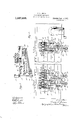
- Figure l is an end view of my improved mechanism, certain of the adjacent parts of the piano mechanism being shown in vertical section;
- Fig. 2 is a vertical section on the line 2 of Fig. 1, showing the more important parts of the mechanism in rear elevation and
- Fig. 3 is a detailed vertical section through one of the operating pneumatics.
- 1 is one of the keys of the piano of which 5 is the wippen, the remainder of the piano-action proper being of ordinary form and requiring no special description.
- the adjustable stops, 6, limit the upward movement of the wippens.
- the player pneumatics which operate the wippens, are arranged in three banks mounted on bars 7, 8 and 9, which extend longitudinally of the piano.
- Each pneumatic consists of an upper stationary plate 10 and a lower movable plate 11, connected by the usual flexible side material.
- Each has on its lower movable face a projecting lug 12, vertically notched to form two cars which are centrally perforated for the passage of a leather pivot member 13.
- Each of these leather pivot members 13 has screwed into it the threaded lower end of a push-rod 14:, the push-rods fromthe pneumatics in the three banks being of different lengths so that their upper ends are brought approxi- Patented A11 14-, 1917.
- each of the push-rods is provided on its upper end with a cap 15, and, by screwing the push-rods into the leather pivots in the cars on the movable plates of the pneumatics, these caps can be brought initially to approximately the right positions to engage the wippens.
- each of the push-rods passes through a pi v otcd stop 16, a felt gasket 17 surrounding the push-rod to permit it to slide vertically with ease.
- These stops are all carried by a longitudinal bar 18, carried by the upper bar 7, which carries the upper bank of pneumat-ics.
- each stop is provided with an adjusting screw 19 which bears on the top of the subjacent pneumatic. .By manipulating the screw 19 the corresponding step can readily be moved up or down, thus varying the vertical position which the cap 15 of the corresponding push-rod occupies when in its normal position.
- the present mechanism affords an exceedingly simple adjustment and depends for its efficacy on the fact that the pneumatics have a considerably greater throw than is required in the operation of the piano. Any of the pneumatics illustrated in the drawings will work entirely satisfactorily if its normal position be either slightly more. collapsed or slightly open than that illustrated. In assembling the action, in the first instance, the caps are so set that this further adjustment can be entirely taken care of by varying the normal amount of extension of the pneumatics. It thus be comes unnecessary to provide any adjusting mechanism between the cap and the movable plate of the pneumatic which operates it, and, as before stated, the cap is never, in practice, adjusted with reference to the movable plate of the pneumatic after the action is assembled.
- a piano player action having a series of note-playing pneumatics, a series of pushrods connected to and operated by the pneumatics, caps on the push-rods adapted at their upper ends to engage directly with the wippens of the piano-action, and adjustable stops arranged to limit the downward throw of the caps to vary the normal distension of the pneumatics, for the purpose set forth.
- a piano player action having noteplaying pneumatics, push-rods connected to and operated by the pneumatics and provided at their upper ends with fixed caps which engage directly with the wippens of the action, and pivoted and adjustable stops lying beneath the caps on the push-rods to limit their downward movement and vary the normal distension of the pneumatics, for the purpose set forth.
- a piano player action including noteplaying pneumatics, push-rods connected to and operated thereby and engaging directly with the wippens of the piano, pivoted stops limiting the downward movement of the push-rods, and adjusting screws for varying the positions of the stops.
- a piano player action including noteplaying pneumatics, push-rods pivoted to the moving parts of the pneumatics and provided with caps at their upper ends to engage directly with the wippens of the piano, pivoted stop-guides through which the pushrods pass, and in which the caps rest when the parts are in normal position, and means for adjusting the vertical position of the stop-guides to vary the normal distension of the pneumatics.
- a piano player action including noteplaying pneumatics, each having a movable side, ears on the movable side of each of the pneumatics, pivotal members passed between said ears, push-rods threaded transversely in said pivotal members, guidestops through which the push-rods pass, caps on the upper ends of the push-rods engaging directly with the wippens of the piano and resting on the guide-stops, and adjusting screws threaded in the guide-stops for varying the vertical position of the caps and the normal distension of the pneumatics.
Landscapes
- Physics & Mathematics (AREA)
- Engineering & Computer Science (AREA)
- Acoustics & Sound (AREA)
- Multimedia (AREA)
- Stringed Musical Instruments (AREA)
Description
a. v. DUMAS. PIANO PLAYER MECHANISM.
APPLICATION FILED FEB. 8, 1916- Patented Aug.
14, 1917. SHEET I.
v2 SHEETS Imam/firm eorye jean/sag,
G. V. DUMAS.
PIANO PLAYER MECHANISM.
APPLICATION FILED FEB-'38. I915- j Pacented Aug. 14,1917.
2 SHEETS-SHEET 2.
} I] III M m 7 1 i W/ .QQ W V UNITED STATES PATENT OFFICE.
GEORGE V. DUIVIAS, 0F GRAND HAVEN, IVIICLIIG Il', ASSIG-NOR TO STORY & CLARK Pr A PIANO COMPANY, OF CHICAGO, ILLINOIS,
CORPORATION OF ILLINOIS.
PIANO-PLAYER IIIECHANISIVI.
Application filed February 18, 1915.
To all whom it may concern:
Be it known that T, Gnonen V. Dorms, a citizen of the United States, residing at Grand Haven, in the county of Ottawa and State of Mich, have invented a new and useful Improvement in Piano-Player Mechanism, of which the following is a specification.
My invention relates to certain new and useful improvements in piano player mechanism and is fully described and explained in the specification and shown in the accompanying drawings, in wnich:
Figure l is an end view of my improved mechanism, certain of the adjacent parts of the piano mechanism being shown in vertical section; Fig. 2 is a vertical section on the line 2 of Fig. 1, showing the more important parts of the mechanism in rear elevation and Fig. 3 is a detailed vertical section through one of the operating pneumatics.
Referring to the drawings, 1 is one of the keys of the piano of which 5 is the wippen, the remainder of the piano-action proper being of ordinary form and requiring no special description. The adjustable stops, 6, limit the upward movement of the wippens.
In the space above the keys and in front of the action is mounted the player-mecha-.
nism which is assembled as a unit and can be placed in and removed from the pianocase without disturbing the piano-action. The f note-sheet, propelling mechanism, tracker-bar, valves and pneumatic connections are arranged in accordance with common practice and are not illustrated, and require no detailed description.
The player pneumatics, which operate the wippens, are arranged in three banks mounted on bars 7, 8 and 9, which extend longitudinally of the piano. Each pneumatic consists of an upper stationary plate 10 and a lower movable plate 11, connected by the usual flexible side material. Each has on its lower movable face a projecting lug 12, vertically notched to form two cars which are centrally perforated for the passage of a leather pivot member 13. Each of these leather pivot members 13 has screwed into it the threaded lower end of a push-rod 14:, the push-rods fromthe pneumatics in the three banks being of different lengths so that their upper ends are brought approxi- Patented A11 14-, 1917.
Serial No. 79,113.,
by two other pneumatics, one in each of the two lower banks. The push-rods are spaced apart, the distance between the wippens of the piano action. Each of the push-rods is provided on its upper end with a cap 15, and, by screwing the push-rods into the leather pivots in the cars on the movable plates of the pneumatics, these caps can be brought initially to approximately the right positions to engage the wippens.
It is not intended that any fine adjustment be given to the caps by screwing the push-rods into or out of these leather pivots, but, on the contrary, the caps are allbrou 'ht to approximately the proper height before the action is placed in the piano and are not adjusted in this mann r thereafter. For the purpose of providing the necessary fine adjustment in a convenient and accessible form, each of the push-rods passes through a pi v otcd stop 16, a felt gasket 17 surrounding the push-rod to permit it to slide vertically with ease. These stops are all carried by a longitudinal bar 18, carried by the upper bar 7, which carries the upper bank of pneumat-ics. These steps form guides for the push-rods and in addition limit their move ment and adjust their position. For this purpose each stop is provided with an adjusting screw 19 which bears on the top of the subjacent pneumatic. .By manipulating the screw 19 the corresponding step can readily be moved up or down, thus varying the vertical position which the cap 15 of the corresponding push-rod occupies when in its normal position.
In practice, after the mechanism has been assembled and the caps brought to an approximate height, as hereinbefore described, the player mechanism is inserted into the piano-case, each push-rod and cap falling immediately below its appropriate wippen. The screws 19 are then manipulated to bring the caps just into contact with the wippens. These screws are readily accessible and can be manipulated with a screw-driver without inconvenience and the finest adjustment is thus possible. The upper throw of the caps is, of course, limited in the usual way by adjusting the throw of the wippens through the medium of the wippen-stop 6. As the player-action requires adjustment from time to time, the proper relation between the caps and wippens can always be maintained with the greatest ease through the mechanism de scribed. The present mechanism affords an exceedingly simple adjustment and depends for its efficacy on the fact that the pneumatics have a considerably greater throw than is required in the operation of the piano. Any of the pneumatics illustrated in the drawings will work entirely satisfactorily if its normal position be either slightly more. collapsed or slightly open than that illustrated. In assembling the action, in the first instance, the caps are so set that this further adjustment can be entirely taken care of by varying the normal amount of extension of the pneumatics. It thus be comes unnecessary to provide any adjusting mechanism between the cap and the movable plate of the pneumatic which operates it, and, as before stated, the cap is never, in practice, adjusted with reference to the movable plate of the pneumatic after the action is assembled. In fact, such adjustment would be exceedingly difficult, because after the player mechanism is in place in the piano, with the caps beneath the wippens, they are practically inaccessible and can be turned only with the utmost difficulty. Thus, by dispensing entirely with adjustment between the cap and the pneumatic, it becomes possible to employ the simplest pos sible connection,merely a straight pushrod.
I realize that considerable variation is possible in the details of this construction without departing from the spirit of my invention; therefore I do not intend to limit myself to the specific form herein shown and described, except as pointed out in the following claims, in which it is my intention to claim all the novelty inherent in the construction as broadly as is permitted by the state of the art.
What I claim as new and desire to secure by Letters Patent is 1. A piano player action having a series of note-playing pneumatics, a series of pushrods connected to and operated by the pneumatics, caps on the push-rods adapted at their upper ends to engage directly with the wippens of the piano-action, and adjustable stops arranged to limit the downward throw of the caps to vary the normal distension of the pneumatics, for the purpose set forth.
2. A piano player action having noteplaying pneumatics, push-rods connected to and operated by the pneumatics and provided at their upper ends with fixed caps which engage directly with the wippens of the action, and pivoted and adjustable stops lying beneath the caps on the push-rods to limit their downward movement and vary the normal distension of the pneumatics, for the purpose set forth.
3. A piano player action including noteplaying pneumatics, push-rods connected to and operated thereby and engaging directly with the wippens of the piano, pivoted stops limiting the downward movement of the push-rods, and adjusting screws for varying the positions of the stops.
4. A piano player action including noteplaying pneumatics, push-rods pivoted to the moving parts of the pneumatics and provided with caps at their upper ends to engage directly with the wippens of the piano, pivoted stop-guides through which the pushrods pass, and in which the caps rest when the parts are in normal position, and means for adjusting the vertical position of the stop-guides to vary the normal distension of the pneumatics.
5. A piano player action including noteplaying pneumatics, each having a movable side, ears on the movable side of each of the pneumatics, pivotal members passed between said ears, push-rods threaded transversely in said pivotal members, guidestops through which the push-rods pass, caps on the upper ends of the push-rods engaging directly with the wippens of the piano and resting on the guide-stops, and adjusting screws threaded in the guide-stops for varying the vertical position of the caps and the normal distension of the pneumatics.
In testimony whereof I have hereunto affixed my hand this 31 day of January, nineteen hundred and sixteen.
GEO. V. DUMAS.
In the presence of two subscribing witnesses:
R. L. SCHMIDT, C. B. BLUMLEY.
Copies of this patent may be obtained for five cents each, by addressing the Commissioner of Patents. Washington, D. C.
Priority Applications (1)
| Application Number | Priority Date | Filing Date | Title |
|---|---|---|---|
| US7911316A US1237263A (en) | 1916-02-18 | 1916-02-18 | Piano-player mechanism. |
Applications Claiming Priority (1)
| Application Number | Priority Date | Filing Date | Title |
|---|---|---|---|
| US7911316A US1237263A (en) | 1916-02-18 | 1916-02-18 | Piano-player mechanism. |
Publications (1)
| Publication Number | Publication Date |
|---|---|
| US1237263A true US1237263A (en) | 1917-08-14 |
Family
ID=3305082
Family Applications (1)
| Application Number | Title | Priority Date | Filing Date |
|---|---|---|---|
| US7911316A Expired - Lifetime US1237263A (en) | 1916-02-18 | 1916-02-18 | Piano-player mechanism. |
Country Status (1)
| Country | Link |
|---|---|
| US (1) | US1237263A (en) |
-
1916
- 1916-02-18 US US7911316A patent/US1237263A/en not_active Expired - Lifetime
Similar Documents
| Publication | Publication Date | Title |
|---|---|---|
| US1237263A (en) | Piano-player mechanism. | |
| US748126A (en) | Automatic playing attachment for musical instruments. | |
| US1107573A (en) | Automatic pneumatic musical instrument. | |
| US1109319A (en) | Musical instrument. | |
| US1195536A (en) | Fobnia | |
| US728965A (en) | Means for modifying the action of strikers in mechanism for playing keyboard instruments. | |
| US261360A (en) | Key-board attachment for musical instruments | |
| US545156A (en) | Pneumatic musical instrument | |
| US1164431A (en) | Harmonic attachment. | |
| US346152A (en) | Meeeitt gally | |
| US671217A (en) | Adjustable tune-sheet support for musical instruments. | |
| US1120775A (en) | Combination grand piano. | |
| US889467A (en) | Expression device for pneumatic musical instruments. | |
| US727725A (en) | Automatic playing attachment for musical instruments. | |
| US904284A (en) | Automatic piano-player. | |
| US992018A (en) | Automatic musical instrument. | |
| US976965A (en) | Retard device. | |
| US1169654A (en) | Coupler for musical instruments. | |
| US1275181A (en) | Music-player sticker-action. | |
| US1682869A (en) | Player grand piano | |
| US79295A (en) | Improvement in key-boards foe pianos | |
| US394005A (en) | Pneumatic action for musical instruments | |
| US712844A (en) | Automatic playing attachment for musical instruments. | |
| US1134249A (en) | Player for musical instruments. | |
| US1064810A (en) | Tracker-box. |