US1237233A - Boiler. - Google Patents
Boiler. Download PDFInfo
- Publication number
- US1237233A US1237233A US65617911A US1911656179A US1237233A US 1237233 A US1237233 A US 1237233A US 65617911 A US65617911 A US 65617911A US 1911656179 A US1911656179 A US 1911656179A US 1237233 A US1237233 A US 1237233A
- Authority
- US
- United States
- Prior art keywords
- header
- headers
- pipes
- boiler
- tubes
- Prior art date
- Legal status (The legal status is an assumption and is not a legal conclusion. Google has not performed a legal analysis and makes no representation as to the accuracy of the status listed.)
- Expired - Lifetime
Links
- XLYOFNOQVPJJNP-UHFFFAOYSA-N water Substances O XLYOFNOQVPJJNP-UHFFFAOYSA-N 0.000 description 72
- 238000010276 construction Methods 0.000 description 16
- 238000010438 heat treatment Methods 0.000 description 13
- 239000007789 gas Substances 0.000 description 9
- 239000002184 metal Substances 0.000 description 9
- 230000004048 modification Effects 0.000 description 5
- 238000012986 modification Methods 0.000 description 5
- 230000008901 benefit Effects 0.000 description 4
- 238000002485 combustion reaction Methods 0.000 description 4
- 230000009471 action Effects 0.000 description 3
- QFXZANXYUCUTQH-UHFFFAOYSA-N ethynol Chemical group OC#C QFXZANXYUCUTQH-UHFFFAOYSA-N 0.000 description 3
- 230000037452 priming Effects 0.000 description 3
- 241001446467 Mama Species 0.000 description 2
- 230000006378 damage Effects 0.000 description 2
- 230000004927 fusion Effects 0.000 description 2
- 230000000630 rising effect Effects 0.000 description 2
- 101100423891 Caenorhabditis elegans qars-1 gene Proteins 0.000 description 1
- 208000027418 Wounds and injury Diseases 0.000 description 1
- 210000005056 cell body Anatomy 0.000 description 1
- 230000008602 contraction Effects 0.000 description 1
- 230000005484 gravity Effects 0.000 description 1
- 230000006872 improvement Effects 0.000 description 1
- 239000012535 impurity Substances 0.000 description 1
- 208000014674 injury Diseases 0.000 description 1
- 238000003780 insertion Methods 0.000 description 1
- 230000037431 insertion Effects 0.000 description 1
- 230000007246 mechanism Effects 0.000 description 1
- 229920000136 polysorbate Polymers 0.000 description 1
- 230000008439 repair process Effects 0.000 description 1
- 238000010025 steaming Methods 0.000 description 1
- 239000008400 supply water Substances 0.000 description 1
Images


Classifications
-
- F—MECHANICAL ENGINEERING; LIGHTING; HEATING; WEAPONS; BLASTING
- F22—STEAM GENERATION
- F22B—METHODS OF STEAM GENERATION; STEAM BOILERS
- F22B21/00—Water-tube boilers of vertical or steeply-inclined type, i.e. the water-tube sets being arranged vertically or substantially vertically
- F22B21/34—Water-tube boilers of vertical or steeply-inclined type, i.e. the water-tube sets being arranged vertically or substantially vertically built-up from water tubes grouped in panel form surrounding the combustion chamber, i.e. radiation boilers
- F22B21/346—Horizontal radiation boilers
Definitions
- My invention relates to an improved form of boiler for high pressure, characterized by extreme simplicity of construction and rapid steaming capacity. Furthermore, the boiler, while of the water circulating type is so constructed as to deliver dry and super- .heated steam without danger of priming.
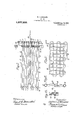
- Figure 1 is a side view of the boiler complete, the casing of theboiler being sectioned to disclosethe inner construction.
- Fig. 2 is atop view of the heating units shown in Fig. 1, the casing being removed in this figure.
- Fig. 3 is an elevation view of the coil employed to heat the feed water as it is suppliedv to the boiler.
- Fig. 4 is a vertical sectional view of the boiler units and 'burner shown in Fig. 1, the casing being removed in this figure.
- Fig. 5 is a detail view of 'a union connector employed.
- Fig..6 shows a modified arrangement of baiiie plates fordistributing the fire through the boiler tubes.
- Fig. 7 is a side view of a modified constructionof boiler.
- Fig. 8 is a top view of the mechanism shown. in Fig. 7.
- Fig. 9 is an enlarged sectional view of one of the left-hand vertical headers shown in Figs. 7 and 8.. y f
- Fig. 10 is a horizontal "sectional view of the header shown in Fig. 9.
- Fig. 11 is an enlarged detail sectional view of the steam header shown in Figs. 7 and 8.
- Fig. 12 shows in top view a portion of one of the heatin units in ⁇ 'which a modified form of water tu e is employed.
- Fig.v 13 isa sectional view of the parts shownv in Fig. 12, taken along the line 13.-,13.. 1 a
- each of thel boiler ⁇ units consists of two vertical tubes or head-V specification of Letters Patent. Patented Aug, 14, 1917, Application filed October 23, 1911. Serial No. 656,179. i
- ers 1 land 2, the ends of which'are closed by plugs 18L and 2a, fused in place by the useof the Oxy-acetylene flame.
- the upper ends of the tubes or-headers 1 and 2 are substantially in line and the tube 1 is considerably shorter than the tube 2.
- a plurality of pipes 3 extend between the headers 1 and 2 in substantially parallel arrangement, the inclination of these pipes being such as to cause Y circulation through them when the water in them is heated. lThis circulation takes place in amanner well-known inconnection with water tube boilers. ⁇ In my boiler the normal water level is at about the middle" of the header 2.
- additional pipes 4 are disposed, which have successively less inclination ⁇ as the top of the section of the boiler is approached until the upper one of such pipes is reached, which is disposed in substantially horizontal position.
- the pipes 3 and 4 are secured attheir ends toJ the headers 1 and 2 by fusionby means of ⁇ the Oxy-acetylene flame, as a result of which' the headers and pipes constitute an integral homogeneous structure incapable of being damaged by any degree of heat less than that required to soften or melt the pipes or ⁇ headers themselves.
- the fire produced by the burner 5 beneath the pipes 3 and 4 causes an extremely rapid circulation of the water through the pipes 3 in a manner well-known in watertube boilers, the water in the lower.
- the units of the boiler may be very simply constructed, and to make up acomplete boiler a plurality of such units is employed, as shown in Fig. 2, from which Iigure it will appear that these units represented by a, c, d, e, f, g, are placed as closely together as consistent with the di mensions of the vertical headers, with the exception that between centralones of such sections a suiicient space is left for a superheating coil 6, which is conformed as in- -dicated in Fig. 1, the lower ends of the coils being farther removed from the burner at the left-hand side than at the right-hand side, so that none of the loops may be overheated.
- the units a to 71.
- the connections 7 are made of small -tubing secured at either end to the corresponding headers by means of connectors, as shown in detail in Fig. 5.
- the end of the tube 7 extends through a taper collar 9, which snugly fits they end of the tube, and around the tube back of the collar an internally threaded sleeve 10 is disposed, the end of mas I 10 is provided with slots 12 in its outer cyr lindrical surface, as indicated, to facilitate screwing the sleeve into properl engagement with the plug 11.
- the lower end of the plug 11 is internally threaded, as indicated, and an inner sleeve 13 is screwed into the lower end to securely hold the washer 14 against y the shoulder formed at the upper end ⁇ of the threaded counterbore formed in the lower end of the plug to receive the tube 13.
- rlhe washer 14 has a small central aperture for preventing an excessive rush of steam from any of the headers 2 into the header 8, if for any reason an excessive demand is made upon the header 8.
- any of the headers 2 may be readily separated from the header 8, if it is necessary to remove one of the units of the boiler from the casing for effecting repairs.
- Each of the headers 2 is provided at its lower end with a pipe connection 15, the lower end. of which connection is threaded into a water header or drum 16, and to fa: cilitate the insertion of the pipe connections 15 they are provided with right and left hand threads, as indicated.
- Eachof the headers 1 is provided with an angle bracket 17 at its upper end, which rests upon the top of the side wall of the boiler casing 18 to support the corresponding end of the boiler unit, and thus the units are held in proper operating position. To remove any unit, therefore, it is only necessary to undo its pipe connection 15 and remove the sleeve 12 connecting it with the corresponding connecting tube 7, after which the unit may be lifted from the boiler and another similar unit inserted in its stead.
- Water is supplied to the water header 16 from a suitable pump through the pipe 19 which conveys the water to a pre-heating coil 20 located within the boiler casing but out of contact with the direct action of the fire from the burner. rlhe lower end of the coil 20 connects by means of a pipe 21 with the water header 16, at or near its central portion, so that water may be supplied to the header and thus to the several loiler units, as required.
- the steam delivered to the steam header 8 is taken from such header toa superheating coil 6 by means of a connection 22 at or near the central portion of the header 8 and from the superheating coil 6 the steam is vided'between the water header 16 and the several vertical headers 2 and the burner 5 to prevent the fire from the burner directly attacking the water in the water header and in the headers 2, as contact with the re would to a considerable degree interfere with the proper circulation of the water through the pipes 3.
- a baille plate 27 is placed upon the top of the upper pipes 4, so asto cause the re to strongly heat the left-hand ends of the pipes 4, as show-n in Fig. 1, tothus entirely convert the entrainedwater into steam and to superheat the steam to a slight degree before it enters the steam header 8.
- the gases of combustion are conveyed from the boiler casing 18 by a suitable flue 26.
- bave plates 25 are disposed over adjacent pairs of the upper pipes 4, the space between such pairs, however, being left uninterrupted so that the gases may pass through such spaces and out from the casing, as described.
- Each of the bailie plates 25 is formed of metal having some elasticity, so that the bent edges of the bave plates whichy extend slightly below the centers of the pipes 4 maybe sprung into place and thus be securely held in proper posltion without the dangerof being jarred loose by motion of the boiler, if used in connection with a self-propelling vehicle.
- the baffle plate 27 is similarly constructed at its edges to engage the upper pipes 4.
- the water vheader 16a so serves as a mud drum, since all of the impurities in the water gradually collect in the lower ends of the headers 2 and pass ddwn in the ipe connections v15 into the header ⁇ 16, om whichv they may be blown periodically, as desired, by opening the blow-oli'l cock 28 connected with one end of the header 16.
- a cover 29 is provided for the boiler casing yto inclose all of the heating'parts and cause the fire to take aproper course to the flue 26.
- the aim plates 251 ⁇ are arranged-similarly to the admir plates 25, shownin Figs. 1 and 4, with f the exception that they arel shorter than the bave plates,v 25,and the short sections are disposed in staggered arrangement so as to cause a.- more perfect distribution of the. fire through the boiler tubes or pipes.
- the tubes 30 extending between the left-hand headers 31 and the right-hand headers 32 are similar to the tubes 3, shown in Fig. 1, with the exception A that the upper ones 30a of such tubes are conformed at their left-hand ends, as indicated i Fig. 9, so that a slot 33 extends horizontally throu h each tube within the header 31, the leftand end of each of these slotted tubes being closed as indicated.'
- This cony struction is employed in connection with the tubes which are to receive and lsuperheat to some degree the steam developed in the remaining portion of the boiler.
- the slots provide for the ready entry into the tubes of the steam produced, but serve to trap to a considerable degree the water which from time to time is thrown violently upward against the upper portion of the header 31.
- the tubes 30b immediately below the slotted tubes 30a have their left-hand ends bent downward, as indicated, and the lower portion of the projecting ends ofthe tubes removed, so that the remaining upper portions operate as deiectors for engagmg the water owing-upward in the header 31 so as to cause it to pass into the upper ones 30 of the water tubes.
- the projecting ends of these tubes are bent in horizontal planes in opposite directions, as indicated in Fig. 10, alternating ,ones of such tubes ybeing bent toward one side of thev header 31, while the intermediate ones vof such tubes are bent toward the other side.
- the lower ones 30v of the tubes are cut olf iiush with the inside surface of the header H 31, as indicated.
- the superheating coil 35 is disposed in substantially horizontal position between the lefthand ends of the lower tubes 30 and the burner, and is in a position to be effectively operated upon by the gases of combustion as they pass to the left to go around the lefthand end of the lower'baiiie plate 34.
- each unit consists of two substantially vertical headers 40 and 41, between which the bent tubes 42 are disposed.
- These tubes are joined to the headers in vertical alinement and alternate onesof the tubes are bent slightly to one side, while the remaining ones are bent to the other side, so that the-total thickness of the section over the tubes will be not to exceed the diameter of the headers.
- the portions of the tubes between the headers, which are o'set as described, are flattened so that they are given an elongated cross-section vertically, the Hatte/ning being done preferably in such a manner that the section is elliptical.
- the tubes may be of larger diameter and fewer in number than is the case when the tubes are not attened.
- a still further advantage of this modification consists in the fact that the tubes bend laterally more readily than if.
- headers are substantially vertical, it is to be understood that any disposition or arrangement of the headers and tubes between them may be made that will result in securing in the same system a first structure in which the water may move by convection rapidly from one point to another along closed and continuous paths so that the heating of the water may be effected as rapidly as possible, and also asecond structure in which the steam developed in the first structure is moved ⁇ rapidly through suitable paths to remove and return the entrained moisture by gravity and produce dry steam.
- the combination of structures as described provides broadly a construction in which the two actions may be of varying extent in the same structures, depending upon the particular operating conditions from time to time and the relationy of the structures to each other, that is to say, certain tubes may for one level of the water in the boiler serve to heat the Water and at other times, for a lower water level, the same tubes may serve to separate the, water from the steam. ⁇ Whatever the relation between the structures, the separating structure is of such a nature that the delivery of wet steam from the boiler is prevented.
- the temperature of the steam may be indicated either absolutely or relatively and, as long as the water level in the boiler is below the high level position, the boiler will deliver dry steam, the temperature of which will be indicated by the device employed.
- the pump should be in operation and when the pump has raised the level of the water in the boilery slightly above the i high' level position,'the boiler will begin to prime slightly as a result of the separating portion of the boiler being unable to handle the large amount of water projected into the steam generated owing to the high level of the 'water in the boiler.
- the water carried river.' in the priming operation is vaporized 'by'.lthe -heat ofthe steam and the slight decreasefin pressure when it reaches the dellvery pipe, and this action absorbs a considerableamount of heat fromv the steam mas with a consequent drop in ythe temperature of the 'steam delivered, which at once is noticeable on the device employed to indicate the temperature.
- the indication afforded by the temperature device will remain practically constant, but, as soon as thev water has passed its high level position, the temperature indicator shows a ⁇ decided drop in the temperature of the steam delivered and thus gives a positive indication that the pump must be stopped in order to prevent priming.
- the boiler After the boiler has been usedfor a short time and the temperature of the steam, 'as indicated by the temperature device, has regained its normal reduced. If, for any reason, the boiler is used too long after shutting olf the pump and lall of the water is turned into steam, no harm is done with the construction above described, since, as vall of the joints are made by fusing the parts together by means of the Oxy-acetylene iame, the boiler is of non-burning construction and may be heated to redness as many times as desired and immediately cooled without injury to 'the boiler. Without the use of a non-burning construction, however, the boiler would, of
- each unit comprising a iiat nest of tubes, said units being support- 4rable units each comprising two substan- ⁇ i ed vertically side byside, a common trans.- ⁇
- a boiler the combination of a plurality 'of lunits each comprising two subs tantially' vertical headers, a plurality of pipesextending between such headers, the lower ones of such pipes "being inclined while the upper one or ones of such pipes are substantially horizontal, a common water header connected to such units, anda. flat' heating coil connected with the water header to" pre-heatthe watery kdelivered to contact to form walls, said preheating coil .
- said units being placed side by side with the corresponding headers in being placed substantially parallel with and v adj acent to one of'said walls.
- a plurality of integral units each comprising two substantially verticaly headers, a plurality of pipes extending between said headers, said units being separate from each other and in substantially vertical planes, the lower ones of such pipes being inclined in one direction, while the upper one or ones of such pipes are not so inclined, said vertical headers each comprising a continuous passageway providing direct communication between the corresponding ends of the pipes, a casing for the units, means for independently suspending the front end of each unit from the casing, said means being secured to the corresponding unit adjacent the top of the front header and a furnace below said units, said units being suspended with their frontI headers over said furnace.
- a boiler the combination of a plurality of functionally independent steam generating units, each unit comprising two continuous substantially vertical headers, the end of the rear headers projecting down below the end of the front header, a plurality of pipes extending between said headers, the lower ones of said pipes being inclined downward toward the rear headers, the upper pipe or pipes of each section being substantially horizontal and pipes of intermediate inclinations between said upper and said lower pipes, a casing for the units, a furnace in the lower part of the casing extending substantially rom the front to the rear of the boiler, said boiler units having their front headers supported above said furnace, a water drum connected to the bottom of the rear headers and extending transversely of said units and a transverse barn plate for protecting said drum and the adjacent ends of the vertical headers from the heat of the furnace.
- each unit comprising two continuons substantially vertical headers, the end of the rear header projecting downward below the end of the front header, a plurality of pipes extending between said headers, the lower ones of said pipes being inclined 'downwardly toward thev rear header, the upper ones of said pipes being infames not so inclined, a casing for the units, a furnace in the lower part of the casing below said units and extending substantially their full length, the units being suspended with their front headers above said furnace substantially vertical round tubular headers having their upper ends practically in horizontal line with each other, one of such headers being shorter than the other, pipes extending from one header to the other, the spacing of the pipes in the shorter header being substantially uniform and smaller than the spacing of the pipes in the longer header, the ends of the lower ones of such pipes connected with the ⁇ shorter vertical header being cut ofll flush with the. inside surface of such header, each vertical header affording direct communication between the corresponding ends of all of
- spacing of the pipes in the shorter header being substantially uniform and smaller than the spacing in the pipes in the longer header, the ends of the upper ones of said pipes extending into one of the said headers and being horizontally slotted.
- a boiler the combination of two substantially vertical headers having their upper ends practically in horizontal alinement with each other, one of said headers bemg shorter than the other and pipes extending from one header to the other, the spacing of the pipes in the shorterl header being substantially uniform and smaller than the spacing in the pipes in the longer header, the ends of the pipes serving as Water return pipes projecting into one of the headers and conformed to serve as deflectors to direct the Water into such pipes.
- a boiler the combination of two4 substantially vertical headers having their upper ends practically in horizontal alinement with each other, one of said headers v being shorter than the other and pipes exthan the spacing in the pipes in the longer header, the ,ends of the pipes serving aswater return pipes projecting into one of the headers and conformed to serve as deflectors todirect the waterinto such pipes and the ends of the pipes above the water return pipes projecting into the last mentioned header and being slotted horizontally.
- a steam header adapted to contain steam only, a plurality of steam generating units having steam delivery pipes connected with the ⁇ header, and a comparatively small diameter tube in said header, said tube having small bore openings through it constituting the only communication between the header and the inside of the tube and serving to deliver the steam from the headers, said ⁇ openings corresponding in number to the generating units and being located adjacent the steam delivery pipes.
- a pair ofheaders having unobstructed passage throughout their length, a 'plurality of tubes joining said headers, said headers and tubes constitutinga single unitary piece of wrought metal, saidtubes being flattened and alternately offset betweenA said headers.
- f tubesI comprising a header affording direct communication be.
- a plurality of unitary, integral wrought metal boiler sections comprising a short header and a longer header and tubes of graduated inclinations joining said headers, a transverse steam header joined to each' section at the top of said longer header, and a transverse water header joined to each section adjacent the bottom Aof said longery header.
- a plurality of similar functionally independent units comprising a-front and a rear vertical header, each of said headers comprising a continuous length of wrought metal tubing, plugs .closing olf the ends o f said headers, said lheaders having each a row ofapertures cut through the walls thereof along one side, the spacing of j the apertures being generally'greater on the l rear header,. ⁇ the lower endof ythe front 10b header being abovethe lowerend yofv the .rear header, a pluralityof tubes having their ends secured-to the edges ofthe apertures in the .header toform closed passages therebetween, said tubes comprising atube inclined downwardly toward they rearheader joining the lower ends of the headers, said tubes and headers all lying in substantially ⁇ f the same plane.
- a functionally complete steam generating unit constructed solely of di'erent lengths and diameters of stock tubing, said unit comprising a front and a rear 'vertical header, each of said headers consisting of a continuous length of wrought metal l tubing having plugs welded to the ends to close the same, said tubes having each a longitudinal row of apertures along one side, the spacing of the apertures being generally greater on the rear header than on the front header, the lower end of the yfront header being above the lower end of the rear header, a plurality of cross tubes having their ends welded to the edges of the apertures in the headers to form closed passages therebetween, said tubes and headers: all lying in substantially the same plane, and tubes of smaller diameter connected to the rear header for supplying water. and for delivering steam.
- a header tubes opening into said header at dierent levels, a second header into which said tubes open, the ends of the tubes being spaced apart farther where they join the second header than where they join the first header, said boiler being organized for operation with the water level in said second header below the, corresponding ends of some tubes and above that of others, a casing surrounding said boiler, said casing containing a furnace in the lower end thereof, said furnace being arranged to heat intensely the rst header and the adjacent ends of the tubes, ⁇ said casing being orthe tubes to a point substantially above the water level during operation and a steam connection joining said second header for withdrawing the steam generated.
- A. water tube boiler comprising a pair of headers, an plurality of inclined connect- 1ng tubes, said tubes being arranged one above the other, other tubes similarly arranged above said iirst tubes and having a different degree of inclination, a furnace and means for heating all of said tubes at one pass of the furnace gases, said boiler being orgamzed for operation with the water level below the upper ones of said second set of tubes.
Landscapes
- Engineering & Computer Science (AREA)
- Chemical & Material Sciences (AREA)
- Combustion & Propulsion (AREA)
- Physics & Mathematics (AREA)
- Thermal Sciences (AREA)
- Mechanical Engineering (AREA)
- General Engineering & Computer Science (AREA)
- Heat-Exchange Devices With Radiators And Conduit Assemblies (AREA)
Description
W. H. WINSLOW.l
BOILER.
APPLICATION FILED o'cr. 23. I9II.
Patented Aug. 14, 1911.l
4 SHEETS-SHEET l.
DSK a 5, 6 S S 6 n w W w. H. wlNsLow.
BOILER.
APPLICATION FILED OCT. 23` 19H. v y 1,237,233. y `4 Patend Aug. 14, l1917.
4 SHEETS-SHEET 2.
T/Kzbnesses l [mwm W'umm/Wwwaw;
@MKM Y Bg MMM' W. H. WINSLOW.
soma.
APPLICATION FILED OCT. 23. |911 1,237,233 Patented Aug. 14, 1917.
4 SHEETS-SHEET 3.
@@@ @QQ M L25@ w /bnesses/ W MM @www Wmtzw WMM l BOILER. `APPLICATION FILED 0CT.23. |911. 1,237,233. PatentedAug.14,1917.
4 SHEETS-SHEET 4. 7
- TED sr 'ENT muon.
WILLIAM H. WINsLoW, or CHICAGb, ILLINOIS, AssICrNoItv "ro WINsLoW SAFETY HIGH- IBEssUHE BoILEB COMPANY, or CHICAGO, ILLINOIS, A lCORPORATION F ILLINOIS.
BOILER.
To all^ whom 'it may concern:
Be it known that I, WILLIAMH. WINsLoW,
' of Illinois, have invented a certain new and l useful Improvement in Boilers, of which the following is a full, clear, concise, and exact description, reference being had to the aocompanying drawings, vforming a part of this specification.
' My invention relates to an improved form of boiler for high pressure, characterized by extreme simplicity of construction and rapid steaming capacity. Furthermore, the boiler, while of the water circulating type is so constructed as to deliver dry and super- .heated steam without danger of priming.
The several drawings illustrating my invention are as follows:
Figure 1 is a side view of the boiler complete, the casing of theboiler being sectioned to disclosethe inner construction.
Fig. 2 is atop view of the heating units shown in Fig. 1, the casing being removed in this figure.
Fig. 3 is an elevation view of the coil employed to heat the feed water as it is suppliedv to the boiler.
Fig. 4 is a vertical sectional view of the boiler units and 'burner shown in Fig. 1, the casing being removed in this figure.
Fig. 5 is a detail view of 'a union connector employed. v
Fig..6 shows a modified arrangement of baiiie plates fordistributing the fire through the boiler tubes. Q
Fig. 7 is a side view of a modified constructionof boiler.
Fig. 8 is a top view of the mechanism shown. in Fig. 7.
Fig. 9 is an enlarged sectional view of one of the left-hand vertical headers shown in Figs. 7 and 8.. y f
Fig. 10 is a horizontal "sectional view of the header shown in Fig. 9.
Fig. 11 is an enlarged detail sectional view of the steam header shown in Figs. 7 and 8.
Fig. 12 shows in top view a portion of one of the heatin units in `'which a modified form of water tu e is employed.
Fig.v 13 isa sectional view of the parts shownv in Fig. 12, taken along the line 13.-,13.. 1 a
Asv lshown in Fig. 1; each of thel boiler` units consists of two vertical tubes or head-V specification of Letters Patent. Patented Aug, 14, 1917, Application filed October 23, 1911. Serial No. 656,179. i
ers 1 land 2, the ends of which'are closed by plugs 18L and 2a, fused in place by the useof the Oxy-acetylene flame. The upper ends of the tubes or-headers 1 and 2 are substantially in line and the tube 1 is considerably shorter than the tube 2. A plurality of pipes 3 extend between the headers 1 and 2 in substantially parallel arrangement, the inclination of these pipes being such as to cause Y circulation through them when the water in them is heated. lThis circulation takes place in amanner well-known inconnection with water tube boilers.` In my boiler the normal water level is at about the middle" of the header 2. Above the pipes 3, additional pipes 4 are disposed, which have successively less inclination `as the top of the section of the boiler is approached until the upper one of such pipes is reached, which is disposed in substantially horizontal position. The pipes 3 and 4 are secured attheir ends toJ the headers 1 and 2 by fusionby means of` the Oxy-acetylene flame, as a result of which' the headers and pipes constitute an integral homogeneous structure incapable of being damaged by any degree of heat less than that required to soften or melt the pipes or` headers themselves. As a result of thev oonstruction described, the fire produced by the burner 5 beneath the pipes 3 and 4 causes an extremely rapid circulation of the water through the pipes 3 in a manner well-known in watertube boilers, the water in the lower.
ones of such pipes being impelled forcibly to the left,.as-shown in Fig. 1, and upward in the header 1 and returning throughthe upper ones of such pipes 3 to the header 2 and thus again tothe lower ones of suchr pipes 3. Afterthe pipes 3 have been securedin place in the header 1, as described,
the inner ends of such pipes are trimmed oii"` Hush with the inner. surface ofthe header 1 to facilitate the circulation described. Thel ebullition produced is so violent that the y; 10
water. is thrown forcibl upward inthe header 1, frequentlystriking the top rof such p header, land, therefore, a small amount ofl the water finds its way with the'steam pro- .l u
duced into the pipes 4, the lower ones ofy such pipes, as they have the` greater inclinawatento the header 2 than dov the upper ones .105Ky tionservingto return more of such surplus and to make the steam .delivered into the upper end of the header 2 perfectly dry. rIhe reason for this is that, as the upper pipes 4 are substantially horizontal, the water which may be caught or trapped 1n such pipes has practically no tendency to liow toward the header 2 but is, on the other hand, entirely converted into steam before it passes from such pipesvto the right into such header 2.l A plurality of horizontally disposed pipes 4 may be employed, 1f desired, in addition to the pipes shown.
Thus it will appear, that in each of th heating sections of the boiler, two circulatory systems are provided, the lower one 1n the pipes 3 serving to convert the water into steam in the manner well-known in water tube boilers, while the upper pipes 4 serve to afford a means for circulation of the wet steam produced by the pipes'S, so that such steam is dried and to a certain degree superheated. Each section or unit is in reality an individual boiler which functions independently of the other sections heating the water, circulating it and separating the steam. In this manner ll secure all of the advantages of a water tube boiler without any of the disadvantages of a construction common in water tube boilers, involving a common steam and water drum located over the heating pipes or tubes. This is a signal advantage, as the boiler constituting' the present invention is designed particularly for use for portable purposes,A as for automobiles, self-propelling trucks, etc. V
From the above description it will appear that the units of the boiler may be very simply constructed, and to make up acomplete boiler a plurality of such units is employed, as shown in Fig. 2, from which Iigure it will appear that these units represented by a, c, d, e, f, g, are placed as closely together as consistent with the di mensions of the vertical headers, with the exception that between centralones of such sections a suiicient space is left for a superheating coil 6, which is conformed as in- -dicated in Fig. 1, the lower ends of the coils being farther removed from the burner at the left-hand side than at the right-hand side, so that none of the loops may be overheated. The units a to 71. inclusive are each provided with a steam connection 7 from the upper end of the vertical header 2 to the common steam header 8, which steam header 1s constructed in a similar-manner to the headers 1 and 2. The connections 7 are made of small -tubing secured at either end to the corresponding headers by means of connectors, as shown in detail in Fig. 5. As shown in this figure, the end of the tube 7 extends through a taper collar 9, which snugly fits they end of the tube, and around the tube back of the collar an internally threaded sleeve 10 is disposed, the end of mamas I 10 is provided with slots 12 in its outer cyr lindrical surface, as indicated, to facilitate screwing the sleeve into properl engagement with the plug 11. The lower end of the plug 11 is internally threaded, as indicated, and an inner sleeve 13 is screwed into the lower end to securely hold the washer 14 against y the shoulder formed at the upper end` of the threaded counterbore formed in the lower end of the plug to receive the tube 13.
rlhe washer 14 has a small central aperture for preventing an excessive rush of steam from any of the headers 2 into the header 8, if for any reason an excessive demand is made upon the header 8. As a result of the construction described any of the headers 2 may be readily separated from the header 8, if it is necessary to remove one of the units of the boiler from the casing for effecting repairs.
Each of the headers 2 is provided at its lower end with a pipe connection 15, the lower end. of which connection is threaded into a water header or drum 16, and to fa: cilitate the insertion of the pipe connections 15 they are provided with right and left hand threads, as indicated. Eachof the headers 1 is provided with an angle bracket 17 at its upper end, which rests upon the top of the side wall of the boiler casing 18 to support the corresponding end of the boiler unit, and thus the units are held in proper operating position. To remove any unit, therefore, it is only necessary to undo its pipe connection 15 and remove the sleeve 12 connecting it with the corresponding connecting tube 7, after which the unit may be lifted from the boiler and another similar unit inserted in its stead. Water is supplied to the water header 16 from a suitable pump through the pipe 19 which conveys the water to a pre-heating coil 20 located within the boiler casing but out of contact with the direct action of the fire from the burner. rlhe lower end of the coil 20 connects by means of a pipe 21 with the water header 16, at or near its central portion, so that water may be supplied to the header and thus to the several loiler units, as required.
The steam delivered to the steam header 8 is taken from such header toa superheating coil 6 by means of a connection 22 at or near the central portion of the header 8 and from the superheating coil 6 the steam is vided'between the water header 16 and the several vertical headers 2 and the burner 5 to prevent the fire from the burner directly attacking the water in the water header and in the headers 2, as contact with the re would to a considerable degree interfere with the proper circulation of the water through the pipes 3. A baille plate 27 is placed upon the top of the upper pipes 4, so asto cause the re to strongly heat the left-hand ends of the pipes 4, as show-n in Fig. 1, tothus entirely convert the entrainedwater into steam and to superheat the steam to a slight degree before it enters the steam header 8. 'After passing from between the upper pipes 4 the gases of combustion are conveyed from the boiler casing 18 by a suitable flue 26.
In order to causeefective distribution of the re between the various pipes 3 and 4 use is made of the construction 'shown in Fig. 4, in which baiile plates 25 are disposed over adjacent pairs of the upper pipes 4, the space between such pairs, however, being left uninterrupted so that the gases may pass through such spaces and out from the casing, as described. Each of the bailie plates 25 is formed of metal having some elasticity, so that the bent edges of the baiile plates whichy extend slightly below the centers of the pipes 4 maybe sprung into place and thus be securely held in proper posltion without the dangerof being jarred loose by motion of the boiler, if used in connection with a self-propelling vehicle. The baffle plate 27 is similarly constructed at its edges to engage the upper pipes 4. Asa result of 'this construction, the baiie plates 25, which extend from the headers 1 tothe left-hand end of the baiile plate 27, cause the gases to take the paths indicated in Fig.- 4` by the arrows, and thus the pipes` 3 and 4 are heated on practically all of their exposed surface and the heating efficiency of the boiler as a whole is rendered a maximum.
Besides, serving as a water sup ly drum for the boiler, the water vheader 16a so serves asa mud drum, since all of the impurities in the water gradually collect in the lower ends of the headers 2 and pass ddwn in the ipe connections v15 into the header` 16, om whichv they may be blown periodically, as desired, by opening the blow-oli'l cock 28 connected with one end of the header 16.
A cover 29 is provided for the boiler casing yto inclose all of the heating'parts and cause the fire to take aproper course to the flue 26. J
In the construction shown in Fig. 6, the baie plates 251` are arranged-similarly to the baie plates 25, shownin Figs. 1 and 4, with f the exception that they arel shorter than the baiile plates,v 25,and the short sections are disposed in staggered arrangement so as to cause a.- more perfect distribution of the. fire through the boiler tubes or pipes.
4`It will be noticed that the burner 5 isl higher at its left-hand end than it is at its iight-hand end, as a result of which the gas ivered to the 'burner by the mixing tube indicated will pass tothe'left-hand end in greater quantity than it will to the righthand end, and thus the lire will be hotter under the portions of the pipes 3 and 4 adjacent to the headers 1. This is a desirable condition in order to stimulate vthe circulation of the water through the pipes 3.
In the modified construction shown in Figs. 7 to 11 inclusive, the tubes 30 extending between the left-hand headers 31 and the right-hand headers 32 are similar to the tubes 3, shown in Fig. 1, with the exception A that the upper ones 30a of such tubes are conformed at their left-hand ends, as indicated i Fig. 9, so that a slot 33 extends horizontally throu h each tube within the header 31, the leftand end of each of these slotted tubes being closed as indicated.' This cony struction is employed in connection with the tubes which are to receive and lsuperheat to some degree the steam developed in the remaining portion of the boiler. The slots provide for the ready entry into the tubes of the steam produced, but serve to trap to a considerable degree the water which from time to time is thrown violently upward against the upper portion of the header 31.
The tubes 30b immediately below the slotted tubes 30a have their left-hand ends bent downward, as indicated, and the lower portion of the projecting ends ofthe tubes removed, so that the remaining upper portions operate as deiectors for engagmg the water owing-upward in the header 31 so as to cause it to pass into the upper ones 30 of the water tubes. To facilitate the engage.- ment by the bent ends of the tubes 30b with the water rising in the header 31, the projecting ends of these tubes are bent in horizontal planes in opposite directions, as indicated in Fig. 10, alternating ,ones of such tubes ybeing bent toward one side of thev header 31, while the intermediate ones vof such tubes are bent toward the other side. The lower ones 30v of the tubes are cut olf iiush with the inside surface of the header H 31, as indicated.
In 'connection withthis modiication, 'baiie I the e ciency of operation of: he boiler is j much increased.
In .this modification, I vprovide imi proved form o'fsuperheating coil 35zformed` y of a tube-which is attened over theburner,
so as to present a maximum of heating sur- 4of combustion as they pass from the burner face and a minimum obstruction to' the gases upward to the tubes of the boiler. The superheating coil 35 is disposed in substantially horizontal position between the lefthand ends of the lower tubes 30 and the burner, and is in a position to be effectively operated upon by the gases of combustion as they pass to the left to go around the lefthand end of the lower'baiiie plate 34. One
end of the superheating coil 35 is connected` steam header 36 only through the holes 38,
which are 4of such a size that their added area is equal to the cross-sectional area of the inner bore of the tube 37. As a result of this construction,`the steam demand made upon any one of the vertical headers 32 ,is prevented from being excessive, and each of these vertical headers is caused to supply its proportionate amount of the steam taken from the boiler and thus the demand upon the several boiler units is equalized.
In the modification shown in Figs. 12 and 13, each unit consists of two substantially vertical headers 40 and 41, between which the bent tubes 42 are disposed. These tubes, as indicated, are joined to the headers in vertical alinement and alternate onesof the tubes are bent slightly to one side, while the remaining ones are bent to the other side, so that the-total thickness of the section over the tubes will be not to exceed the diameter of the headers. The portions of the tubes between the headers, which are o'set as described, are flattened so that they are given an elongated cross-section vertically, the Hatte/ning being done preferably in such a manner that the section is elliptical. In this way the amount of heating surface presented to the hot gases of combustion is increased relatively to the volume of the water in the tubes and the construction is comparatively simple to make'. Another advantage of this modification is that the tubes may be of larger diameter and fewer in number than is the case when the tubes are not attened. A still further advantage of this modification consists in the fact that the tubes bend laterally more readily than if.
they were round in cross-section, as a result of which the expansion and contraction of the tubes does not exert as serious strain upon .the headers and supporting devices as though the tubes were not free to deect laterally. The same advantageis obtained newness in connection with the type of superheating coil 'l5 shown in Figs. '7 and 8.
While I have shown throughout the drawings diHerent modifications in which the headers are substantially vertical, it is to be understood that any disposition or arrangement of the headers and tubes between them may be made that will result in securing in the same system a first structure in which the water may move by convection rapidly from one point to another along closed and continuous paths so that the heating of the water may be effected as rapidly as possible, and also asecond structure in which the steam developed in the first structure is moved `rapidly through suitable paths to remove and return the entrained moisture by gravity and produce dry steam. By my invention, the combination of structures as described provides broadly a construction in which the two actions may be of varying extent in the same structures, depending upon the particular operating conditions from time to time and the relationy of the structures to each other, that is to say, certain tubes may for one level of the water in the boiler serve to heat the Water and at other times, for a lower water level, the same tubes may serve to separate the, water from the steam.` Whatever the relation between the structures, the separating structure is of such a nature that the delivery of wet steam from the boiler is prevented.
In connection with the boiler construction described above, I find that a very satisfactory indication of when the water level is raised above a proper working point is aforded by a tendency of the boiler to prime for such condition.- In' practice, it will be understood, the pump used with the boiler must be of such a capacity as to supply water to the boiler slightly in excess of the maximum demand that may be made upon the boiler. By means of any suitabledevice, a`s,ior example, a thermometer, the
temperature of the steam may be indicated either absolutely or relatively and, as long as the water level in the boiler is below the high level position, the boiler will deliver dry steam, the temperature of which will be indicated by the device employed. For this condition the pump should be in operation and when the pump has raised the level of the water in the boilery slightly above the i high' level position,'the boiler will begin to prime slightly as a result of the separating portion of the boiler being unable to handle the large amount of water projected into the steam generated owing to the high level of the 'water in the boiler. The water carried river.' in the priming operation is vaporized 'by'.lthe -heat ofthe steam and the slight decreasefin pressure when it reaches the dellvery pipe, and this action absorbs a considerableamount of heat fromv the steam mamas with a consequent drop in ythe temperature of the 'steam delivered, which at once is noticeable on the device employed to indicate the temperature. As a result, for all normal working conditions, the indication afforded by the temperature device will remain practically constant, but, as soon as thev water has passed its high level position, the temperature indicator shows a` decided drop in the temperature of the steam delivered and thus gives a positive indication that the pump must be stopped in order to prevent priming. After the boiler has been usedfor a short time and the temperature of the steam, 'as indicated by the temperature device, has regained its normal reduced. If, for any reason, the boiler is used too long after shutting olf the pump and lall of the water is turned into steam, no harm is done with the construction above described, since, as vall of the joints are made by fusing the parts together by means of the Oxy-acetylene iame, the boiler is of non-burning construction and may be heated to redness as many times as desired and immediately cooled without injury to 'the boiler. Without the use of a non-burning construction, however, the boiler would, of
course, be seriously damaged by permitting the pump to remain inoperative for too long an interval.
While I haveshown my invention in the particular embodiment herein described, I
do not, however, limit myself to its exact construction, but may use any equivalent thereof that may suggest itself to those skilled in the art. v
What I claim is:
1. In a boiler, the combination of two substantially vertical headers, and a plurality of pipes extending between suchl headers, the lower one or ones of such pipesbeing inclined, theupper one or onesof ysuch pipes being'substantially horizontal, and the intermediate pipes havinginclinations gradually changing from the inclination of the lowerv pipe or pipes toa horizontal position, each header affording direct communication between the corresponding ends of .all of said pipes.
2. In a boiler, vthe lcombinationof two substantially vertical headers having their upper ,f ends lpractically in horizontal line witheach other, one of such headers being Shorter than the other, pipes extending from one lheader to the other, the spacing .of the pipes'in the shorter header being sub- I l stantially uniform and' smaller than the spacing of the pipes in the longer header, each .header affording direct communication between the corresponding ends of Iall of said pipes. l
. .A-f 3. In a boiler, the combination vof twoff substantially vertical headers having their upper ends practically inI horizontal line with each 'otherA one of such headers being shorter than the other, pipes extending yfrom one header to the other, thespacing of the pipes in the shorter header being sub.-
-stantially uniform and smaller than the spacing of the pipes in the long'erheader,- l,such pipes securedinthe headers by fusion.
'4. In a boiler, the combination of two substantially vertical headers having their upper ends practically in horizontal line with each other, one rof such headers being shorter than the other, pipes extending n from one header ,to the other, the spaclng of the pipes in the shorter header being substantially uniform and' smaller than the spacing of thepipes in the longer header, such pipes secured inthe headers b fusion, and metal `plugs fused into the en s of the headers.
' 5. In a boiler, the combination of a plurality of independently functioning sepatially vertical headers, a plurality of pipes extending 'between such headers, the lower ones of such pipes being inclined while the upper one or ones ofsuch pipes are', s ubstantially horizontal, each unit comprising a iiat nest of tubes, said units being support- 4rable units each comprising two substan-` i ed vertically side byside, a common trans.-`
verse steam header lfor such units, and a flat superheatingcoil disposed vertically between two such units. l
6. In` a boiler, the combination of a plurality 'of lunits each comprising two subs tantially' vertical headers, a plurality of pipesextending between such headers, the lower ones of such pipes "being inclined while the upper one or ones of such pipes are substantially horizontal, a common water header connected to such units, anda. flat' heating coil connected with the water header to" pre-heatthe watery kdelivered to contact to form walls, said preheating coil .such header, said units being placed side by side with the corresponding headers in being placed substantially parallel with and v adj acent to one of'said walls.l
7. In a boiler, the combination of a` plui ralityof functionallyV independent;wrought f metal .steam yIgg'enerating units, each `unitl com rising two continuous' substantially vertlcal headers, a` plurality of pipes yex-t tendingbetween `such headers, ,the lowerones not so inclined, said vertical headers each comprising a continuous passageway providing direct communication between the corresponding ends of the connected tubes, a common steam header, readily separable unions joining said units and said steam header, a common water header connected to said units, said water header being disposed 'below and connected to the lower ends of the longer vertical headers and readily separable pipe connections for connecting the water headers with the adjacent vertical headers.
8. In a boiler, the combination of a plurality of integral units, each comprising two substantially verticaly headers, a plurality of pipes extending between said headers, said units being separate from each other and in substantially vertical planes, the lower ones of such pipes being inclined in one direction, while the upper one or ones of such pipes are not so inclined, said vertical headers each comprising a continuous passageway providing direct communication between the corresponding ends of the pipes, a casing for the units, means for independently suspending the front end of each unit from the casing, said means being secured to the corresponding unit adjacent the top of the front header and a furnace below said units, said units being suspended with their frontI headers over said furnace.
9. In a boiler, the combination of a plurality of functionally independent steam generating units, each unit comprising two continuous substantially vertical headers, the end of the rear headers projecting down below the end of the front header, a plurality of pipes extending between said headers, the lower ones of said pipes being inclined downward toward the rear headers, the upper pipe or pipes of each section being substantially horizontal and pipes of intermediate inclinations between said upper and said lower pipes, a casing for the units, a furnace in the lower part of the casing extending substantially rom the front to the rear of the boiler, said boiler units having their front headers supported above said furnace, a water drum connected to the bottom of the rear headers and extending transversely of said units and a transverse baie plate for protecting said drum and the adjacent ends of the vertical headers from the heat of the furnace.
10. In a boiler, the combination of a plurality of functionally independent steam generating units, each unit comprising two continuons substantially vertical headers, the end of the rear header projecting downward below the end of the front header, a plurality of pipes extending between said headers, the lower ones of said pipes being inclined 'downwardly toward thev rear header, the upper ones of said pipes being infames not so inclined, a casing for the units, a furnace in the lower part of the casing below said units and extending substantially their full length, the units being suspended with their front headers above said furnace substantially vertical round tubular headers having their upper ends practically in horizontal line with each other, one of such headers being shorter than the other, pipes extending from one header to the other, the spacing of the pipes in the shorter header being substantially uniform and smaller than the spacing of the pipes in the longer header, the ends of the lower ones of such pipes connected with the `shorter vertical header being cut ofll flush with the. inside surface of such header, each vertical header affording direct communication between the corresponding ends of all of the pipes of the unit of which said header is a part.
l2. In a boiler, the ycombination of two substantially Vertical headers having their upper ends practically in horizontal alinement with each other, one of said headers being shorter than the other, and pipes exf tending from one header to the other, the
spacing of the pipes in the shorter header being substantially uniform and smaller than the spacing in the pipes in the longer header, the ends of the upper ones of said pipes extending into one of the said headers and being horizontally slotted.
13. ln a boiler, the combination of two substantially vertical headers having their upper ends practically in horizontal alinement with each other, one of said headers bemg shorter than the other and pipes extending from one header to the other, the spacing of the pipes in the shorterl header being substantially uniform and smaller than the spacing in the pipes in the longer header, the ends of the pipes serving as Water return pipes projecting into one of the headers and conformed to serve as deflectors to direct the Water into such pipes.
14. ln a boiler, the combination of two4 substantially vertical headers having their upper ends practically in horizontal alinement with each other, one of said headers v being shorter than the other and pipes exthan the spacing in the pipes in the longer header, the ,ends of the pipes serving aswater return pipes projecting into one of the headers and conformed to serve as deflectors todirect the waterinto such pipes and the ends of the pipes above the water return pipes projecting into the last mentioned header and being slotted horizontally.
15. In combination two substantially vertical headerscomprising a front and a rear header, said rearl header comprising a length of tubing havin j a row of circular perforations in one' si e Wall: thereof, saidfront header comprisinga length of tubing having a row of circularperforations in one side wall thereof the perforations in said rear header being spaced apart farther than in said front header, means closing olf the top and bottoms of both headers, a plurality of pipes between said headers and having their ends joined to the edges of said aperture to formclosed passages between said headers, the lowermost one of said pipesbeing inclined downward toward said rear header, said upper pipes being provided with means in' the upper end of said front headers for restricting the flow of waterinto said pipes and a steam connection for drawing 0E steam from the upper end of the rear header.
16. In combination aplurality of independv ently functioning boiler units, a common steam header supported above the water level in said unit, and being freepof water at all times, delivery pipes for each of said units, said pipes being connected to said header and being adapted to deliver steam only to said header, an equalizing pipe lying within said header, said pipe having apertures of small size through the side walls thereof, 'said pipe communicating with the interior of said headers through saidv apertures only, the total area of said apertures being `substantially the same as the cross-sectional area of said equalizing pipe.
'-17. In a boiler, a steam header adapted to contain steam only, a plurality of steam generating units having steam delivery pipes connected with the` header, and a comparatively small diameter tube in said header, said tube having small bore openings through it constituting the only communication between the header and the inside of the tube and serving to deliver the steam from the headers, said `openings corresponding in number to the generating units and being located adjacent the steam delivery pipes.
18. In combination, a pair ofheaders having unobstructed passage throughout their length, a 'plurality of tubes joining said headers, said headers and tubes constitutinga single unitary piece of wrought metal, saidtubes being flattened and alternately offset betweenA said headers.
- pipes,
f tubesI comprising a header affording direct communication be. 75
tween the corresponding endsof all of said o 20. In combination, a plurality of unitary, integral wrought metal boiler sections, said sections comprising a short header and a longer header and tubes of graduated inclinations joining said headers, a transverse steam header joined to each' section at the top of said longer header, anda transverse water header joined to each section adjacent the bottom Aof said longery header.
21. In combination a plurality of functionally independent steam generating units, common means for heating said units, a common steam header adapted during normal operation to contain steam only, individual steam connections joining said headers and y.said units, saidconnections containing each ay steam flow restricting orifice tending to equalize'the steam delivered by said units. 95
22. In a boiler, a plurality of similar functionally independent units,each unit comprising a-front and a rear vertical header, each of said headers comprising a continuous length of wrought metal tubing, plugs .closing olf the ends o f said headers, said lheaders having each a row ofapertures cut through the walls thereof along one side, the spacing of j the apertures being generally'greater on the l rear header,.\the lower endof ythe front 10b header being abovethe lowerend yofv the .rear header, a pluralityof tubes having their ends secured-to the edges ofthe apertures in the .header toform closed passages therebetween, said tubes comprising atube inclined downwardly toward they rearheader joining the lower ends of the headers, said tubes and headers all lying in substantially` f the same plane.
23. In a boiler a plurality of. similarffunc-,i-ll l tionally `independent units, eachunit co"1n.y
prising a front andarear vertical-header, v each'of said headerscomprisinga continu-.fy l ous length ofwroughtmetaltubing; plugs closing toil the:` ends of saidv headers, said 1 20 headershaving each a row of apertures cut through the walls thereof along one side, the spacing of the-apertures being generallyv greater on the rear header, the lower end ofthe front header being above the lower end of the rear header, a plurality of tubes having their ends secured to the edges of the apertures in the headers to form closed passages therebetween, said tube inclined down- Q, Larmes wardly toward the rear header joining the lower ends of the headers, said tubes and headers all lying in substantially the same plane, said units being placed together with their corresponding headers in' contact, a transverse steam drum at the top of said headers, a transverse water drum at the botc. of metal, the space between said tubes being substantially uniformly7 greater at the longer header than at the shorter header.
25. In a boiler, a pair o'f unitary vertical headers, a plurality of tubes joined at their ends to said headers and having unobstructed communication therewith, said tubes and said headers constituting a unitary integral piece of metal, said tubes being of graduated inclinations from the top to the bottom of said headers.
26. In a boiler, a functionally complete steam generating unit constructed solely of di'erent lengths and diameters of stock tubing, said unit comprising a front and a rear 'vertical header, each of said headers consisting of a continuous length of wrought metal l tubing having plugs welded to the ends to close the same, said tubes having each a longitudinal row of apertures along one side, the spacing of the apertures being generally greater on the rear header than on the front header, the lower end of the yfront header being above the lower end of the rear header, a plurality of cross tubes having their ends welded to the edges of the apertures in the headers to form closed passages therebetween, said tubes and headers: all lying in substantially the same plane, and tubes of smaller diameter connected to the rear header for supplying water. and for delivering steam.
27. Ina high pressure boiler the combination of a plurality of independently functioning steam generating units, each unit.
comprising a front and a rear header and a .plurality of cross tubes interconnecting said headers, the lowermost tubes being inclined from the lower end of the front header to l othe normal operation of the boiler so that some ofthe tubes lie above the water level and the lowermost tubes lie below the water level, a casing surrounding said boiler, and a furnace 'below said units, said casing having means for passing the gases from the furnace directly through the tubes below the water level and through the tubes above the water level at one pass, the lower end of said front header being supported over said furnace and being adapted to be highly heated thereby.
28. In a steam boiler, a header, tubes opening into said header at dierent levels, a second header into which said tubes open, the ends of the tubes being spaced apart farther where they join the second header than where they join the first header, said boiler being organized for operation with the water level in said second header below the, corresponding ends of some tubes and above that of others, a casing surrounding said boiler, said casing containing a furnace in the lower end thereof, said furnace being arranged to heat intensely the rst header and the adjacent ends of the tubes,` said casing being orthe tubes to a point substantially above the water level during operation and a steam connection joining said second header for withdrawing the steam generated.
29. A. water tube boiler comprising a pair of headers, an plurality of inclined connect- 1ng tubes, said tubes being arranged one above the other, other tubes similarly arranged above said iirst tubes and having a different degree of inclination, a furnace and means for heating all of said tubes at one pass of the furnace gases, said boiler being orgamzed for operation with the water level below the upper ones of said second set of tubes.
In witness whereof, I hereunto subscribe rylname this 18th day of ctober, A. D.,
WILLIAM H. `WINSLOVV.
Priority Applications (1)
| Application Number | Priority Date | Filing Date | Title |
|---|---|---|---|
| US65617911A US1237233A (en) | 1911-10-23 | 1911-10-23 | Boiler. |
Applications Claiming Priority (1)
| Application Number | Priority Date | Filing Date | Title |
|---|---|---|---|
| US65617911A US1237233A (en) | 1911-10-23 | 1911-10-23 | Boiler. |
Publications (1)
| Publication Number | Publication Date |
|---|---|
| US1237233A true US1237233A (en) | 1917-08-14 |
Family
ID=3305051
Family Applications (1)
| Application Number | Title | Priority Date | Filing Date |
|---|---|---|---|
| US65617911A Expired - Lifetime US1237233A (en) | 1911-10-23 | 1911-10-23 | Boiler. |
Country Status (1)
| Country | Link |
|---|---|
| US (1) | US1237233A (en) |
-
1911
- 1911-10-23 US US65617911A patent/US1237233A/en not_active Expired - Lifetime
Similar Documents
| Publication | Publication Date | Title |
|---|---|---|
| US1237233A (en) | Boiler. | |
| US2293040A (en) | Steam generator | |
| US2994308A (en) | Thermal liquid heater | |
| US2088724A (en) | Boiler and furnace installation | |
| US1633975A (en) | Superheater baffle | |
| US861040A (en) | Water-tube steam-generator. | |
| US1924850A (en) | Boiler | |
| US2067669A (en) | Steam boiler | |
| US1670955A (en) | Gravity-feed water heater | |
| US2578332A (en) | Water tube firebox for locomotive boilers | |
| US1917533A (en) | Water tube boiler | |
| US2684663A (en) | Steam boiler | |
| US227475A (en) | pefess | |
| US752301A (en) | Elbeidge g | |
| US1906125A (en) | Boiler with interdeck superheater | |
| US289796A (en) | Steam boileb | |
| US1746240A (en) | Boiler construction | |
| US1603500A (en) | Boiler | |
| US963257A (en) | Superheating-boiler. | |
| US2031498A (en) | Heating unit | |
| US1222476A (en) | Steam-boiler superheater. | |
| US1965749A (en) | Steam generator | |
| US871235A (en) | Heater. | |
| US2366720A (en) | Vapor generator | |
| US2042036A (en) | Steam generator |