US1237206A - Printing-machine. - Google Patents
Printing-machine. Download PDFInfo
- Publication number
- US1237206A US1237206A US9089516A US9089516A US1237206A US 1237206 A US1237206 A US 1237206A US 9089516 A US9089516 A US 9089516A US 9089516 A US9089516 A US 9089516A US 1237206 A US1237206 A US 1237206A
- Authority
- US
- United States
- Prior art keywords
- inking
- rolls
- machine
- printing
- roll
- Prior art date
- Legal status (The legal status is an assumption and is not a legal conclusion. Google has not performed a legal analysis and makes no representation as to the accuracy of the status listed.)
- Expired - Lifetime
Links
Images


Classifications
-
- B—PERFORMING OPERATIONS; TRANSPORTING
- B41—PRINTING; LINING MACHINES; TYPEWRITERS; STAMPS
- B41F—PRINTING MACHINES OR PRESSES
- B41F31/00—Inking arrangements or devices
- B41F31/02—Ducts, containers, supply or metering devices
- B41F31/14—Applications of messenger or other moving transfer rollers
Definitions
- the object of this invention is to enable the plate carrying cylinder of a printing machine, particularly a color printing machine or unit such as may be used, if desired, in multiple color printing machines, to be elevated from the impression cylinder and sheet of paper which may be passing through the machine, so that while it is thus elevated it will notV rint, although the remainder of the mac ine will still continue to run, reference being had to my co-pending application Serial No. 88,547.
- the inking rolls adjacent to theplate carrying cylinder are carried in a vertically movable bearing'bar at each end; and hand operated means is provided for elevating said inking rolls away from the plate carrying cylinder when it is desired for mounting plates on said cylinder or for any other purpose.
- This arrangement is 'such as not to interfere with the remainder of the inking train or apparatus.
- Figure 1 is a side elevation of the machine, lparts being broken away.
- Fig. 2 is a section on line 4-4 of ⁇ cylinder upward out of printing position.
- Fig. 5 is a vertical longitudinal section through the upper part of the machine on line 7 7 of'Fig. 2.
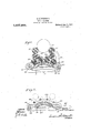
- Fig. 6 is a section through a portion of the machine on line 8-8 of Fig. 2, showing the means for mounting the lower portion of the inking train and for elevating the same.
- Fig. 7 is a part of Fig. 6 with the lower portion of the inking train elevated.
- a main frame 10 carrying an impression cylinder 11 and a plate carrying cylinder 12 above and coperating with said impression cylinder.
- the sheet of paper 13 is fed by said cylinders between and through them during the printing operation, and moves from a paper roll 14 carried by a suitable support 15.
- the machine is driven from any suitable source of power applied to the lshaft 16 which carries a bevel pinion 17 meshing with a bevel gear 18 secured on a shaft 19 of the impression cylinder.
- a spur gear y20 transmits power from said shaft 19 to a spur gear 21 secured on the shaft 22 of the plate carrying cylinder.
- the shaft 22 is mounted at each end in a vertically movable bearing 23 slidable between vertical guide ways 24 which areV secured"to the frame 10.
- A'pair of ears 25 ⁇ extend down from each bearing 23 and to said ears a link 26 -is pivoted at its upper end and said link at its lower end is pivoted to the horizontal lever 27 which is fulcrumed to the main frame at 28.
- the other end of the lever is yoke-shaped and embraces a cam 29 on a cam shaft 3() mounted in the main frame and actuated by a hand lever 31.
- the hand lever 31 When the machine is in printing condition the hand lever 31 is upright as shown in Fig. 1, and the plate carrying cylinder engages the sheet of paper 13.
- an inking bracket 35 secured which carries an ink fountain 36 on its Lipper end, having an inking roll 37 therein and an adjustable bottom plate 38 and set screws 39 for adjusting the bottom 38 to the inking roll 37 in order to regulate the feed of ink.
- the roll 41 at each end has bearing in the end of bearing bar 43, fulcrumed to the inking bracket at 44.
- r1 ⁇ he arms 43 are elevated at each revolution of the roll 40 by' cams 45 on the ends thereof, and such elevation of the arms 43 moves the roll 41 into engagement with the inking roll 37 in the ink fountain.
- the roll 37 in the ink fountain is actuated by an eccentric ring 46 operated by the cam 45, said eccentric forcing a bar 47 upwardly and moving an arm 48 carrying a pawlv 49 which engages a ratchet 50 on the spindle of the inking roll 37 Therefore at very revolution of the roll 40 the cam 45 will give said ratchet feed one operation and will cause a corresponding rotary movement of the inking roll 37.
- inking rolls 51 which cooperate with the roll 40 and there are longitudinally vibratory ink rolls 52 and a train of ink rolls 53, all mounted in U-shaped bearings 54 secured to the inking brackets. Thereby the inking rolls are readily mounted in their bearings and are vertically movable.
- the roll 40 is driven by a chain of gears 55 and 56, the latter meshing with the gear 21 which drives the plate carrying cylinder. This gearing is indicated in Fig. 1.
- the arrangement and manner of mounting of the inking rolls so far described constitute no new part of this machine, but are described herein in order to make the invention clear.
- Each cam shaft 62 has an arm 63 extending therefrom rigidlyand such arm is pivoted to a longitudinally connectin bar 64, so that when one of said cam sha ts 62 is operated by the hand lever 65 secured thereto, both cam shafts and all the cams thereonV will be operated and the bars 60 elevated for -lifting the inking rolls 53 entirely clear of the plate carrying cylinder.
- the normal position of these parts is shown in Fig. 6 where the lever 65 extends upwardly. When said lever is thrown down into the position of Eig. 7 the bars 60 will be elevated and the rolls 53 lifted away from the plate carrying cylinder.
- a printing machine including a frame, a plate carrying cylinder mounted therein so as to be movable, means for moving said cylinder, inking rolls adapted to ride on said plate carrying cylinders, spindles for said rolls, means for mounting said spindles which permit the movement of the rolls, a pair of cam shafts extending transversely through the machine, cams on said shafts, a bar under the spindles which rests upon the cams, and means for simultaneously.' operating said cam shafts.
- a printing machine including a frame, a plate carrying cylinder mounted thereinso as to be vertically movable, means for. vertically moving said cylinder, inking rolls adapted to ride on said plate carrying cylinders, spindles for said rolls, meansV for mounting said spindles which permit the vertical movement of the rolls, a pair of cam shafts extending transversely through the machine, cams on said shafts, a har under the spindles at each end of said rolls and which rests upon the cams, arms connected with the cam shafts, bars for connecting said arms, and means for operating one of said cam shafts whereby all of the cams will be simultaneously operated and the inking rolls elevated.
Landscapes
- Inking, Control Or Cleaning Of Printing Machines (AREA)
Description
G. K. HENDERSON..
PRINTING MACHINE.
APPucATlQN FILED APR. 13. 191e.
Patented Aug. 14, 1917.
"3 SHEETS-s115514.
INVENTUI? M A Gea/e K//fwffsalv G. K. HENDERSON. PRINTING MCHINE. APPLIcATloN FILED APR. 13. 1916.
Patented Aug. 14, 1917.
3 SHEETS--SHEET 2.
WITNESSES:
l N V E N TUR v reqs Afl/Mpman I f nnss EJK] HENDERSON.
PRINTING MACHINE.
APPLICATION FILED APR. 13V.' 1916.
Patented AlIg. 14, 1917.
3 SHEETS-'SHEET 3. y
' 1 Afro/Mfrs UNITED STATES PATENT oEErcE.
GEORGE K. HENDERSON, OF INDIANAPOLIS, INDIANA, ASSIGNOR T0 INTERNATIONAL PRINTING COMPANY,YOF INDIANAPOLIS, INDIANA, A CORPORATION.
PRINTING-MACHINE.
I Specification of Letters Patent. Patented Aug. 14, 1917.
Application filed April 13, 1916. Serial No. 90,895.
To all whoml t may concern:
Be it known that I, GEORGE K. HENDER- soN, a citizen of the United States, and a resident of Indianapolis, county of Marion, and State of Indiana, have invented a certain new and useful Printing-Machine; and I do hereby declare that the following is a full, clear, and exact description thereof, reference being had to the accompanying drawings, in which like letters refer to like parts.
The object of this invention is to enable the plate carrying cylinder of a printing machine, particularly a color printing machine or unit such as may be used, if desired, in multiple color printing machines, to be elevated from the impression cylinder and sheet of paper which may be passing through the machine, so that while it is thus elevated it will notV rint, although the remainder of the mac ine will still continue to run, reference being had to my co-pending application Serial No. 88,547.
This enables one to readily stop the machine from printing although it otherwise is operating, for the purpose of changing, adjusting or doing any other necessary thing to the inking: train 0r apparatus.
Along with the foregoing is such a mounting of the inking train or rolls that they will readily rise with the plate carrying cylinder without interfering with such movement. The inking rolls adjacent to theplate carrying cylinder are carried in a vertically movable bearing'bar at each end; and hand operated means is provided for elevating said inking rolls away from the plate carrying cylinder when it is desired for mounting plates on said cylinder or for any other purpose. This arrangement is 'such as not to interfere with the remainder of the inking train or apparatus. y
The foregoing and other features of the invention will be understood from the following description and claims.
In the drawings, Figure 1 is a side elevation of the machine, lparts being broken away. Fig. 2 is a section on line 4-4 of` cylinder upward out of printing position.
Fig. 5 is a vertical longitudinal section through the upper part of the machine on line 7 7 of'Fig. 2. Fig. 6 is a section through a portion of the machine on line 8-8 of Fig. 2, showing the means for mounting the lower portion of the inking train and for elevating the same. Fig. 7 is a part of Fig. 6 with the lower portion of the inking train elevated.
There is shown herein a main frame 10 carrying an impression cylinder 11 and a plate carrying cylinder 12 above and coperating with said impression cylinder. The sheet of paper 13 is fed by said cylinders between and through them during the printing operation, and moves from a paper roll 14 carried by a suitable support 15.
The machine is driven from any suitable source of power applied to the lshaft 16 which carries a bevel pinion 17 meshing with a bevel gear 18 secured on a shaft 19 of the impression cylinder. A spur gear y20 transmits power from said shaft 19 to a spur gear 21 secured on the shaft 22 of the plate carrying cylinder.
The shaft 22 is mounted at each end in a vertically movable bearing 23 slidable between vertical guide ways 24 which areV secured"to the frame 10. A'pair of ears 25` extend down from each bearing 23 and to said ears a link 26 -is pivoted at its upper end and said link at its lower end is pivoted to the horizontal lever 27 which is fulcrumed to the main frame at 28. The other end of the lever is yoke-shaped and embraces a cam 29 on a cam shaft 3() mounted in the main frame and actuated by a hand lever 31. When the machine is in printing condition the hand lever 31 is upright as shown in Fig. 1, and the plate carrying cylinder engages the sheet of paper 13. When, however, it is desired to stop the printing, or for any purpose` to elevate the plate carrying cylinder 12,` the lever 31 is moved down to a horizontal position, as shown in, Fig. 4, which elevates the lever 27, the plate carrying cylinder 12, and the train of inking rolls above saidcylinder. This can be done without interfering with the continuous operation of the shaft 16 and the im-l pression cylinder 11.
When it is desired to return parts to their normal position for printing the hand lever 31 is turned upward to its vertical position.
Upon each side of the main frame there is an inking bracket 35 secured which carries an ink fountain 36 on its Lipper end, having an inking roll 37 therein and an adjustable bottom plate 38 and set screws 39 for adjusting the bottom 38 to the inking roll 37 in order to regulate the feed of ink. Beneath the fountain there is a large inking roll 40 and upon it a roll 41 travels for transferring ink thereto from the inking roll 37 in the ink fountain. The roll 41 at each end has bearing in the end of bearing bar 43, fulcrumed to the inking bracket at 44. r1`he arms 43 are elevated at each revolution of the roll 40 by' cams 45 on the ends thereof, and such elevation of the arms 43 moves the roll 41 into engagement with the inking roll 37 in the ink fountain. In this manner the ink is transferred from the roll 37 to the roll 40. The roll 37 in the ink fountain is actuated by an eccentric ring 46 operated by the cam 45, said eccentric forcing a bar 47 upwardly and moving an arm 48 carrying a pawlv 49 which engages a ratchet 50 on the spindle of the inking roll 37 Therefore at very revolution of the roll 40 the cam 45 will give said ratchet feed one operation and will cause a corresponding rotary movement of the inking roll 37.
There are other inking rolls 51 which cooperate with the roll 40 and there are longitudinally vibratory ink rolls 52 and a train of ink rolls 53, all mounted in U-shaped bearings 54 secured to the inking brackets. Thereby the inking rolls are readily mounted in their bearings and are vertically movable. The roll 40 is driven by a chain of gears 55 and 56, the latter meshing with the gear 21 which drives the plate carrying cylinder. This gearing is indicated in Fig. 1. The arrangement and manner of mounting of the inking rolls so far described constitute no new part of this machine, but are described herein in order to make the invention clear.
The mounting of the lower rolls 53 of the inking train in U-shaped bearings extending upwardly enables them to ride on the plate carrying cylinder 12 and transfer ink thereto while the machine is printing. When the plate carrying cylinder 12, however, is elevated, it forces said inking rolls upwardly in their bearings and therefore the inking rolls do not prevent such upward movement of the plate carrying cylinder.
In order to hold the inking rolls away from the plate carrying cylinder when plates are being placed thereon or for any other purpose, the following means is provided. On each side of the machine there is an arcuate bar 60 with its upper surface Copies of this patent may be obtained 'for normally engaging the spindles of the inking rolls 53, said plate lying between the main frame and the ends of the rolls 53. The ends of the bar 60 rest upon cams 61 secured on cam shafts 62 which extend transversely through the machine. Each cam shaft 62 has an arm 63 extending therefrom rigidlyand such arm is pivoted to a longitudinally connectin bar 64, so that when one of said cam sha ts 62 is operated by the hand lever 65 secured thereto, both cam shafts and all the cams thereonV will be operated and the bars 60 elevated for -lifting the inking rolls 53 entirely clear of the plate carrying cylinder. The normal position of these parts is shown in Fig. 6 where the lever 65 extends upwardly. When said lever is thrown down into the position of Eig. 7 the bars 60 will be elevated and the rolls 53 lifted away from the plate carrying cylinder.
The invention is not limited to the particular details of construction herein referred to Ifor the sake of explaining the general nature of the invention as said 'parts mayI be changed or modified in ways known to those skilled in the art without departing from this invention.
What I claim as the invention is:
1. A printing machine including a frame, a plate carrying cylinder mounted therein so as to be movable, means for moving said cylinder, inking rolls adapted to ride on said plate carrying cylinders, spindles for said rolls, means for mounting said spindles which permit the movement of the rolls, a pair of cam shafts extending transversely through the machine, cams on said shafts, a bar under the spindles which rests upon the cams, and means for simultaneously.' operating said cam shafts.
2. A printing machine including a frame, a plate carrying cylinder mounted thereinso as to be vertically movable, means for. vertically moving said cylinder, inking rolls adapted to ride on said plate carrying cylinders, spindles for said rolls, meansV for mounting said spindles which permit the vertical movement of the rolls, a pair of cam shafts extending transversely through the machine, cams on said shafts, a har under the spindles at each end of said rolls and which rests upon the cams, arms connected with the cam shafts, bars for connecting said arms, and means for operating one of said cam shafts whereby all of the cams will be simultaneously operated and the inking rolls elevated.
In witness whereof, I have hereunto aHixed my signature.
GEORGE K. HENDERSON.
five cents each, by addressing the Commissioner of latents, Washington, D. C, 1
Priority Applications (1)
| Application Number | Priority Date | Filing Date | Title |
|---|---|---|---|
| US9089516A US1237206A (en) | 1916-04-13 | 1916-04-13 | Printing-machine. |
Applications Claiming Priority (1)
| Application Number | Priority Date | Filing Date | Title |
|---|---|---|---|
| US9089516A US1237206A (en) | 1916-04-13 | 1916-04-13 | Printing-machine. |
Publications (1)
| Publication Number | Publication Date |
|---|---|
| US1237206A true US1237206A (en) | 1917-08-14 |
Family
ID=3305024
Family Applications (1)
| Application Number | Title | Priority Date | Filing Date |
|---|---|---|---|
| US9089516A Expired - Lifetime US1237206A (en) | 1916-04-13 | 1916-04-13 | Printing-machine. |
Country Status (1)
| Country | Link |
|---|---|
| US (1) | US1237206A (en) |
-
1916
- 1916-04-13 US US9089516A patent/US1237206A/en not_active Expired - Lifetime
Similar Documents
| Publication | Publication Date | Title |
|---|---|---|
| US1237206A (en) | Printing-machine. | |
| US247463A (en) | johnston | |
| US1120771A (en) | Lithographic press. | |
| US621893A (en) | Match-printing machine | |
| US472666A (en) | Island | |
| US1867860A (en) | Printing press | |
| US581436A (en) | Printing-machine | |
| US404058A (en) | Printing-machine | |
| US373356A (en) | District | |
| US656383A (en) | Box-printing machine. | |
| US638237A (en) | Printing-press. | |
| US547577A (en) | Platen printing machine | |
| US626871A (en) | Inking apparatus for printing-presses | |
| US633616A (en) | Printing-press. | |
| US424097A (en) | Cylinder printing-machine | |
| US1002934A (en) | Feeding mechanism for presses. | |
| US651971A (en) | Multicolor-printing press. | |
| US432785A (en) | bouyier | |
| US580509A (en) | Half to george arthur johnston | |
| US871923A (en) | Arrangement for giving movement to automatic numbering mechanisms for printing-machines. | |
| US723736A (en) | Color-printing machine. | |
| US193538A (en) | Improvement in rotary printing-machines for printing on boards | |
| US757460A (en) | Printing-press. | |
| US612873A (en) | Walter scott | |
| US473142A (en) | Island |