US12290146B2 - Sole of shoe and shoe - Google Patents
Sole of shoe and shoe Download PDFInfo
- Publication number
- US12290146B2 US12290146B2 US18/305,783 US202318305783A US12290146B2 US 12290146 B2 US12290146 B2 US 12290146B2 US 202318305783 A US202318305783 A US 202318305783A US 12290146 B2 US12290146 B2 US 12290146B2
- Authority
- US
- United States
- Prior art keywords
- foot
- midsole
- sole
- support portion
- medial
- Prior art date
- Legal status (The legal status is an assumption and is not a legal conclusion. Google has not performed a legal analysis and makes no representation as to the accuracy of the status listed.)
- Active, expires
Links
Images


Classifications
-
- A—HUMAN NECESSITIES
- A43—FOOTWEAR
- A43B—CHARACTERISTIC FEATURES OF FOOTWEAR; PARTS OF FOOTWEAR
- A43B13/00—Soles; Sole-and-heel integral units
- A43B13/14—Soles; Sole-and-heel integral units characterised by the constructive form
-
- A—HUMAN NECESSITIES
- A43—FOOTWEAR
- A43B—CHARACTERISTIC FEATURES OF FOOTWEAR; PARTS OF FOOTWEAR
- A43B7/00—Footwear with health or hygienic arrangements
- A43B7/14—Footwear with health or hygienic arrangements with foot-supporting parts
- A43B7/1405—Footwear with health or hygienic arrangements with foot-supporting parts with pads or holes on one or more locations, or having an anatomical or curved form
- A43B7/1415—Footwear with health or hygienic arrangements with foot-supporting parts with pads or holes on one or more locations, or having an anatomical or curved form characterised by the location under the foot
- A43B7/142—Footwear with health or hygienic arrangements with foot-supporting parts with pads or holes on one or more locations, or having an anatomical or curved form characterised by the location under the foot situated under the medial arch, i.e. under the navicular or cuneiform bones
-
- A—HUMAN NECESSITIES
- A43—FOOTWEAR
- A43B—CHARACTERISTIC FEATURES OF FOOTWEAR; PARTS OF FOOTWEAR
- A43B13/00—Soles; Sole-and-heel integral units
- A43B13/02—Soles; Sole-and-heel integral units characterised by the material
- A43B13/12—Soles with several layers of different materials
- A43B13/125—Soles with several layers of different materials characterised by the midsole or middle layer
-
- A—HUMAN NECESSITIES
- A43—FOOTWEAR
- A43B—CHARACTERISTIC FEATURES OF FOOTWEAR; PARTS OF FOOTWEAR
- A43B13/00—Soles; Sole-and-heel integral units
- A43B13/14—Soles; Sole-and-heel integral units characterised by the constructive form
- A43B13/18—Resilient soles
- A43B13/181—Resiliency achieved by the structure of the sole
- A43B13/186—Differential cushioning region, e.g. cushioning located under the ball of the foot
-
- A—HUMAN NECESSITIES
- A43—FOOTWEAR
- A43B—CHARACTERISTIC FEATURES OF FOOTWEAR; PARTS OF FOOTWEAR
- A43B13/00—Soles; Sole-and-heel integral units
- A43B13/14—Soles; Sole-and-heel integral units characterised by the constructive form
- A43B13/18—Resilient soles
- A43B13/187—Resiliency achieved by the features of the material, e.g. foam, non liquid materials
- A43B13/188—Differential cushioning regions
-
- A—HUMAN NECESSITIES
- A43—FOOTWEAR
- A43B—CHARACTERISTIC FEATURES OF FOOTWEAR; PARTS OF FOOTWEAR
- A43B3/00—Footwear characterised by the shape or the use
-
- A—HUMAN NECESSITIES
- A43—FOOTWEAR
- A43B—CHARACTERISTIC FEATURES OF FOOTWEAR; PARTS OF FOOTWEAR
- A43B7/00—Footwear with health or hygienic arrangements
- A43B7/14—Footwear with health or hygienic arrangements with foot-supporting parts
- A43B7/1405—Footwear with health or hygienic arrangements with foot-supporting parts with pads or holes on one or more locations, or having an anatomical or curved form
- A43B7/1415—Footwear with health or hygienic arrangements with foot-supporting parts with pads or holes on one or more locations, or having an anatomical or curved form characterised by the location under the foot
- A43B7/1445—Footwear with health or hygienic arrangements with foot-supporting parts with pads or holes on one or more locations, or having an anatomical or curved form characterised by the location under the foot situated under the midfoot, i.e. the second, third or fourth metatarsal
-
- A—HUMAN NECESSITIES
- A43—FOOTWEAR
- A43B—CHARACTERISTIC FEATURES OF FOOTWEAR; PARTS OF FOOTWEAR
- A43B7/00—Footwear with health or hygienic arrangements
- A43B7/14—Footwear with health or hygienic arrangements with foot-supporting parts
- A43B7/1405—Footwear with health or hygienic arrangements with foot-supporting parts with pads or holes on one or more locations, or having an anatomical or curved form
- A43B7/1475—Footwear with health or hygienic arrangements with foot-supporting parts with pads or holes on one or more locations, or having an anatomical or curved form characterised by the type of support
- A43B7/149—Pads, e.g. protruding on the foot-facing surface
-
- A—HUMAN NECESSITIES
- A43—FOOTWEAR
- A43B—CHARACTERISTIC FEATURES OF FOOTWEAR; PARTS OF FOOTWEAR
- A43B7/00—Footwear with health or hygienic arrangements
- A43B7/14—Footwear with health or hygienic arrangements with foot-supporting parts
- A43B7/24—Insertions or other supports preventing the foot canting to one side , preventing supination or pronation
-
- A—HUMAN NECESSITIES
- A43—FOOTWEAR
- A43B—CHARACTERISTIC FEATURES OF FOOTWEAR; PARTS OF FOOTWEAR
- A43B5/00—Footwear for sporting purposes
- A43B5/002—Mountain boots or shoes
-
- A—HUMAN NECESSITIES
- A43—FOOTWEAR
- A43B—CHARACTERISTIC FEATURES OF FOOTWEAR; PARTS OF FOOTWEAR
- A43B5/00—Footwear for sporting purposes
- A43B5/06—Running shoes; Track shoes
Definitions
- the present invention relates to a sole of a shoe and a shoe.
- a sole of a shoe comprising: a forefoot support portion supporting a forefoot of a foot of a wearer; a midfoot support portion supporting a midfoot of the foot of the wearer; and a rearfoot support portion supporting a rearfoot of the foot of the wearer, the forefoot support portion, the midfoot support portion, and the rearfoot support portion being connected in order from a front side toward a rear side, wherein a ground contact portion having a portion positioned on a lowermost line connecting a lowermost point of the forefoot support portion and a lowermost point of the rearfoot support portion in a side view is formed in a medial-foot-side region of a bottom surface of the midfoot support portion, and a protrusion protruding toward a medial foot side is formed on a medial-foot-side side surface of the midfoot support portion.
- FIG. 1 is a bottom view of a shoe according to a first embodiment of the present invention
- FIG. 2 is a medial-foot-side side view of the shoe according to the first embodiment of the present invention
- FIG. 3 is a cross-sectional view taken along line III-III in FIG. 1 ;
- FIG. 4 is a bottom view schematically illustrating an outline and a fixed line of the shoe according to the first embodiment of the present invention
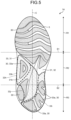
- FIG. 5 is a bottom view of a shoe according to a second embodiment of the present invention.
- FIG. 6 is a cross-sectional view illustrating a shoe according to a third embodiment of the present invention and corresponds to a cross-sectional view taken along line III-III in FIG. 1 ;
- FIG. 7 is a bottom view of a shoe according to a fourth embodiment of the present invention.
- FIG. 8 is a cross-sectional view taken along line VIII-VIII in FIG. 7 .
- FIG. 1 is a bottom view of a shoe 1 according to a first embodiment of the present invention.
- FIG. 1 only the shoe 1 for a left foot is illustrated. Since the shoe 1 has a left-right symmetrical structure for a left foot and a right foot, only the shoe 1 for a left foot is described in the present embodiment, and the description of the shoe 1 for a right foot is omitted.
- a direction in which a shoe center axis C, which is a perpendicular line passing through the center of shoe 1 in a bottom view of the shoe 1 , extends is referred to as a front-rear direction
- a direction orthogonal to the front-rear direction in the bottom view of the shoe 1 is referred to as a foot width direction.
- a direction from the heel toward the toe of the shoe 1 in the front-rear direction is referred to as a front
- a direction from the toe toward the heel of the shoe 1 in the front-rear direction is referred to as a rear.
- a median side of a foot in the anatomical position is referred to as a medial foot side
- the side opposite to the median side of the foot in the anatomical position is referred to as a lateral foot side. That is, the side closer to the median line in the anatomical position is referred to as the medial foot side, and the side farther from the median line in the anatomical position is referred to as the lateral foot side.
- a vertical direction means a direction orthogonal to both the front-rear direction and the foot width direction unless otherwise specified.
- a sole 3 includes a forefoot support portion R 1 that supports the forefoot of a foot of a wearer with a standard body shape, a midfoot support portion R 2 that supports the midfoot of a foot of a wearer with a standard body shape, and a rearfoot support portion R 3 that supports the rearfoot of a foot of a wearer with a standard body shape.
- the forefoot support portion R 1 , the midfoot support portion R 2 , and the rearfoot support portion R 3 are connected in order from the front side toward the rear side of the sole 3 .
- a line along the foot width direction passing through a position corresponding to about 37% of the dimension of the sole 3 from the front end of the sole 3 in the front-rear direction is defined as a first boundary line S 1
- a line along the foot width direction passing through a position corresponding to about 71% of the dimension of the sole 3 from the front end of the sole 3 in the front-rear direction is defined as a second boundary line S 2
- the first boundary line S 1 is a line roughly along the MP joint of a wearer with a standard body shape.
- the second boundary line S 2 is a line roughly along the Chopart joint of a wearer with a standard body shape.
- the forefoot support portion R 1 is positioned in front of the first boundary line S 1 .
- the midfoot support portion R 2 is positioned between the first boundary line S 1 and the second boundary line S 2 .
- the rearfoot support portion R 3 is positioned behind the second boundary line S 2 .
- FIG. 2 is a medial-foot-side side view of the shoe 1 according to the first embodiment of the present invention.
- the shoe 1 is preferably a running shoe but may be a shoe for other sports, a walking shoe, a climbing shoe, or the like.
- the shoe 1 includes an upper 2 and the sole 3 .
- the upper 2 is positioned above the sole 3 .
- the upper 2 includes an upper body 20 , a shoe tongue 21 , and a shoelace 22 .
- the upper body 20 covers an instep side part of a foot of a wearer.
- the upper body 20 is formed with a foot insertion opening 20 a and a throat portion 20 b at its upper portion.
- the foot insertion opening 20 a is an opening for inserting the foot of the wearer into the upper body 20 .
- the throat portion 20 b is an opening communicating with the foot insertion opening 20 a and extending to the front side from the foot insertion opening 20 a .
- a plurality of string passing portions 20 c spaced apart from each other in the front-rear direction is provided.
- FIG. 2 illustrates only the string passing portions 20 c provided on the medial-foot-side side edge of the throat portion 20 b .
- the string passing portions 20 c are only required to allow the shoelace 22 to pass through.
- the string passing portions 20 c are, for example, through holes that pass through the upper body 20 in the vertical direction.
- the shoe tongue 21 is a member for protecting the instep of the wearer.
- the shoe tongue 21 covers the throat portion 20 b inside the upper body 20 .
- the shoe tongue 21 is fixed to the upper body 20 by stitching, welding, bonding, or a combination thereof.
- the material of the upper body 20 and the shoe tongue 21 is, for example, woven fabric, knitted fabric, synthetic leather, or resin.
- the material of the upper body 20 and the shoe tongue 21 is preferably a double raschel warp knitted fabric knitted with polyester yarn. Note that the material of the upper body 20 and the shoe tongue 21 is not limited to those exemplified.
- the shoelace 22 is a string-like member that is alternately passed through the string passing portions 20 c provided at one side edge of the throat portion 20 b in the foot width direction and the string passing portions 20 c provided at the other side edge in the foot width direction.
- the shoelace 22 is detachably attached to the upper body 20 .
- the upper 2 including the shoe tongue 21 and the shoelace 22 is described as an example, but the upper 2 may have a monosock structure in which a portion corresponding to the shoe tongue 21 is integrated with an ankle portion of the upper body 20 .
- a hook-and-loop fastener may be used instead of the shoelace 22 to bring the upper body 20 into close contact with the foot. If a hook-and-loop fastener is used to bring the upper body 20 into close contact with the foot, the string passing portions 20 c are not formed in the upper body 20 .
- the sole 3 is positioned below the upper 2 .
- the sole 3 covers the sole of the wearer.
- the sole 3 is fixed to the upper 2 by stitching, welding, bonding, or a combination thereof.
- the sole 3 includes an outsole 30 and a midsole 31 .
- the sole 3 includes an inner sole (not illustrated) that covers the lower opening of the upper body 20 .
- the inner sole is fixed to the upper surface of the midsole 31 by bonding or welding.
- the inner sole is fixed to the lower edge of the upper body 20 by stitching.
- the shoe 1 may include an insole. If the shoe 1 includes an insole, the insole is installed on the sole 3 inside the upper 2 .
- the sole 3 may have a structure in which the inner sole is omitted.
- the midsole 31 is positioned on the upper surface of the outsole 30 .
- the midsole 31 is positioned between the upper 2 and the outsole 30 .
- the midsole 31 is a soft member having a smaller Young's modulus than the outsole 30 .
- the midsole 31 has a cushioning property.
- the midsole 31 is disposed over the entire region of the forefoot support portion R 1 , the midfoot support portion R 2 , and the rearfoot support portion R 3 .
- the midsole 31 has a first midsole portion 32 and a second midsole portion 33 . Note that, in FIG. 2 , the first midsole portion 32 is diamond-hatched, and the second midsole portion 33 is dot-hatched in order to facilitate understanding.
- the second midsole portion 33 is formed separately from the first midsole portion 32 .
- the second midsole portion 33 is fixed to the first midsole portion 32 by welding, adhesion, or a combination thereof.
- the hardness of the second midsole portion 33 is lower than the hardness of the first midsole portion 32 .
- the material of the first midsole portion 32 and the material of the second midsole portion 33 are, for example, a resin foam material and a rubber foam material.
- the first midsole portion 32 is disposed over the entire region of the forefoot support portion R 1 , the midfoot support portion R 2 , and the rearfoot support portion R 3 .
- the second midsole portion 33 is disposed below a portion of the first midsole portion 32 positioned in the midfoot support portion R 2 .
- a cutout 32 a recessed upward is formed in a lower surface of the portion of the first midsole portion 32 positioned in the midfoot support portion R 2
- the second midsole portion 33 is disposed in the cutout 32 a .
- the cutout 32 a opens downward and toward the medial foot side.
- the side view shape of an upper surface 33 g of the second midsole portion 33 is a curved shape protruding upward.
- the side view shape of the upper surface 33 g of the second midsole portion 33 is a shape along the medial longitudinal arch of the foot or a shape approximating the medial longitudinal arch of the foot.
- the outer shape of the second midsole portion 33 is indicated by a broken line, the second midsole portion 33 is dot-hatched, and the outsole 30 is diagonal-hatched in order to facilitate understanding.
- the second midsole portion 33 is disposed only in a medial-foot-side region of the midfoot support portion R 2 in the present embodiment.
- the second midsole portion 33 is only required to be disposed at least in a medial-foot-side region of the midfoot support portion R 2 .
- the second midsole portion 33 is only required to be disposed below at least a part or all of the medial longitudinal arch of the foot.
- the bottom surface of the second midsole portion 33 is a medial-foot-side region of the bottom surface of the midfoot support portion R 2 .
- the second midsole portion 33 is deformed by receiving the load when the shoe 1 comes contact with the ground to absorb an impact when the shoe 1 comes into contact with the ground.
- the bottom view shape of the second midsole portion 33 is a triangular shape in which the width in the front-rear direction narrows from the medial foot side toward the lateral foot side in the present embodiment.
- the second midsole portion 33 includes a ground contact portion 33 a that comes into contact with the ground.
- the ground contact portion 33 a is formed on the bottom surface of the second midsole portion 33 .
- the ground contact portion 33 a is the outsole 30 attached to the bottom surface of the second midsole portion 33 in the present embodiment.
- the ground contact portion 33 a is positioned below the medial longitudinal arch of the foot.
- the position of the ground contact portion 33 a in the front-rear direction is preferably within a region of 30% to 60% of the dimension of the sole 3 in the front-rear direction from the rear end of the sole 3 .
- the position of the ground contact portion 33 a in the foot width direction is preferably positioned on the medial foot side relative to the shoe center axis C. As illustrated in FIG.
- the ground contact portion 33 a has a portion positioned on a lowermost line Z along the front-rear direction connecting a lowermost point P 1 of the forefoot support portion R 1 and a lowermost point P 2 of the rearfoot support portion R 3 in a side view.
- FIG. 3 is a cross-sectional view taken along line III-III in FIG. 1 .
- the medial-foot-side side surface of the second midsole portion 33 is the medial-foot-side side surface of the midfoot support portion R 2 .
- the medial-foot-side side surface of the second midsole portion 33 is formed with a protrusion 33 b protruding toward the medial foot side.
- the protrusion 33 b is formed over the entire length of the medial-foot-side side surface of the second midsole portion 33 .
- the protrusion 33 b is preferably in a region ranging from 30% to 60% of the dimension of the sole 3 in the front-rear direction from the rear end of the sole 3 .
- the protrusion 33 b includes a protruding end surface 33 c facing the medial foot side.
- the protruding end surface 33 c has a first protruding end surface 33 d and a second protruding end surface 33 e .
- the first protruding end surface 33 d extends upward from the medial-foot-side edge of a bottom surface 31 b of the midsole 31 (the bottom surface of the second midsole portion 33 ) so as to be positioned toward the medial foot side.
- the second protruding end surface 33 e is continuous with the first protruding end surface 33 d and extends upward so as to be positioned toward the lateral foot side.
- the boundary between the first protruding end surface 33 d and the second protruding end surface 33 e is a vertex 33 f of the protrusion 33 b positioned on the medial-most foot side.
- the vertex 33 f is a point of the protruding end surface 33 c where the inclination direction is switched.
- the vertex 33 f extends in the front-rear direction.
- the vertex 33 f of the protrusion 33 b is preferably positioned on the medial foot side relative to the virtual straight line L and below the center of the virtual straight line L in the vertical direction.
- the upper surface 33 g of the second midsole portion 33 is inclined downward from the medial foot side toward the lateral foot side.
- the cross-sectional shape of the upper surface 33 g of the second midsole portion 33 along the foot width direction is an inclined shape inclined downward from the medial foot side toward the lateral foot side.
- the outsole 30 is disposed below the midsole 31 .
- the outsole 30 is a hard member having a larger Young's modulus than the midsole 31 .
- the material of the outsole 30 is, for example, a material containing rubber as a main component and secondary components. Examples of the secondary components include a plasticizer, a reinforcing agent, and a crosslinking agent.
- the outsole 30 is partially disposed in the forefoot support portion R 1 , the midfoot support portion R 2 , and the rearfoot support portion R 3 .
- the outsole 30 is partially attached to the bottom surface 31 b of the midsole 31 .
- the distance D1 and the distance D2 at the same position of the sole 3 in the front-rear direction preferably satisfy a relationship of D1>D2 in a region ranging from 30% to 60% of the dimension of the sole 3 in the front-rear direction from the rear end of the sole 3 .
- the distance D1 and the distance D2 more preferably satisfy the relationship D1>D2 in a region ranging from 20% to 80% of the dimension of the sole 3 in the front-rear direction from the rear end of the sole 3 .
- the medial longitudinal arch of the foot is supported from the medial foot side by the protrusion 33 b , it is possible to control the falling of the foot toward the medial foot side. That is, according to the present embodiment, it is possible to control the collapse of the medial longitudinal arch and the falling of the foot toward the medial foot side to stably support the midfoot of the sole of the wearer.
- To control the collapse of the medial longitudinal arch and the falling of the foot toward the medial foot side as in the present embodiment is particularly effective when a runner is increasingly fatigued. That is, it is possible to control overpronation under increased fatigue due to running.
- the protrusion 33 b is formed on the medial-foot-side side surface of the midsole 31 , and when a straight line connecting the medial-foot-side edge of the upper surface 31 a of the midsole 31 and the medial-foot-side edge of the bottom surface 31 b of the midsole 31 is defined as the virtual straight line L, the vertex 33 f of the protrusion 33 b is positioned on the medial foot side relative to the virtual straight line L and below the center of the virtual straight line L in the vertical direction.
- the vertex 33 f positioned at the boundary between the first protruding end surface 33 d and the second protruding end surface 33 e is positioned at a position separated upward from the ground, and it is possible to prevent the protrusion 33 b from locally bending when the medial longitudinal arch of the foot is about to fall toward the medial foot side. That is, when the medial longitudinal arch of the foot is about to fall toward the medial foot side, the compressive deformation of the protrusion 33 b can be promoted. Therefore, it is possible to further control the falling of the foot toward the medial foot side.
- the distance D1 in the foot width direction between the medial-foot-side portion M 1 of the sole outline M and the medial-foot-side portion N 1 of the fixed line N is longer than the distance D2 in the foot width direction between the lateral-foot-side portion M 2 of the sole outline M and the lateral-foot-side portion N 2 of the fixed line N.
- the outsole 30 serving as the ground contact portion 33 a and the other outsole 30 are provided independently of each other.
- the load generated when the ground contact portion 33 a comes into contact with the ground can be easily transmitted only to the second midsole portion 33 formed with the ground contact portion 33 a , and it is possible to more reliably compress and deform the second midsole portion 33 . Therefore, it is possible to enhance the cushioning property of the second midsole portion 33 of the sole 3 positioned below the medial longitudinal arch of the foot. In other words, it is possible for the second midsole portion 33 of the sole 3 positioned below the medial longitudinal arch of the foot to easily absorb an impact when the ground contact portion 33 a comes into contact with the ground.
- the second midsole portion 33 positioned below the medial longitudinal arch where the wearer is likely to feel a thrust is formed separately from the first midsole portion 32 , and the hardness of the second midsole portion 33 is lower than the hardness of the first midsole portion 32 .
- the upper surface 33 g of the second midsole portion 33 is inclined downward from the medial foot side toward the lateral foot side.
- the structure of the protrusion 33 b is not limited to the illustrated example.
- the vertex 33 f of the protrusion 33 b is preferably positioned below the center of the virtual straight line L in the vertical direction, but may be positioned at the same height as the center of the virtual straight line L in the vertical direction or above the center of the virtual straight line L in the vertical direction.
- the shape of the protruding end surface 33 c of the protrusion 33 b is preferably the illustrated shape, but may be a linear shape along the vertical direction or may be a shape inclined from the upper side toward the lower side so as to be positioned toward the medial foot side.
- the ground contact portion 33 a disposed in the midfoot support portion R 2 is the outsole 30 , but the ground contact portion 33 a may be a part of the midsole 31 .
- a part or all of the bottom surface of the second midsole portion 33 may be served as the ground contact portion 33 a .
- the outsole 30 is only required to be disposed at least in the forefoot support portion R 1 and the rearfoot support portion R 3 .
- the bottom view shape of the second midsole portion 33 illustrated in FIG. 1 , the side view shape of the upper surface 33 g of the second midsole portion 33 illustrated in FIG. 2 , and the cross-sectional shape of the upper surface 33 g of the second midsole portion 33 along the foot width direction illustrated in FIG. 3 are not limited to the illustrated examples, and may be appropriately changed.
- the cross-sectional shape of the upper surface 33 g of the second midsole portion 33 along the foot width direction may be a flat shape along the foot width direction.
- FIG. 5 is a perspective view of a shoe 1 A according to a second embodiment of the present invention.
- a shoe 1 A according to the second embodiment is different from the shoe 1 according to the first embodiment in the range of a second midsole portion 33 .
- the range of the second midsole portion 33 is indicated by a broken line.
- the second midsole portion 33 is disposed from a medial-foot-side region of a midfoot support portion R 2 to a lateral-foot-side region of a rearfoot support portion R 3 .
- the second midsole portion 33 includes a first portion 33 h , a second portion 33 i , and a third portion 33 j .
- the first portion 33 h is disposed in the medial-foot-side region of the midfoot support portion R 2 .
- the third portion 33 j extends obliquely rearward from the first portion 33 h toward the lateral foot side.
- the third portion 33 j is disposed over a part of a central region of the midfoot support portion R 2 in the foot width direction and a part of a central region of the rearfoot support portion R 3 in the foot width direction.
- the second portion 33 i extends from the third portion 33 j rearward and toward the lateral foot side.
- the second portion 33 i is disposed over a part of a lateral-foot-side region of the midfoot support portion R 2 , the lateral-foot-side region of the rearfoot support portion R 3 , and a heel-side region of the rearfoot support portion R 3 .
- the second portion 33 i reaches the rear end of the rearfoot support portion R 3 .
- the second midsole portion 33 is disposed avoiding a medial-foot-side region of the rearfoot support portion R 3 .
- a ground contact portion 33 a is disposed on the bottom surface of the first portion 33 h and the bottom surface of the second portion 33 i .
- the ground contact portion 33 a is disposed in the medial-foot-side region of the midfoot support portion R 2 of the bottom surface of the second midsole portion 33 and in the lateral-foot-side region and the heel-side region of the rearfoot support portion R 3 of the bottom surface of the second midsole portion 33 .
- the third portion 33 j may be omitted.
- the second midsole portion 33 is only required to be disposed in the medial-foot-side region of the midfoot support portion R 2 and the lateral-foot-side region of the rearfoot support portion R 3 . In the present embodiment, it is possible to achieve the same effects as those of the first embodiment described above.
- the second midsole portion 33 is disposed in the central region of the midfoot support portion R 2 in the foot width direction and in the central region of the rearfoot support portion R 3 in the foot width direction.
- FIG. 6 is a cross-sectional view illustrating a shoe 1 B according to a third embodiment of the present invention and corresponds to a cross-sectional view taken along line III-III in FIG. 1 .
- the shoe 1 B according to the third embodiment is different from the shoe 1 according to the first embodiment in that a plate 4 is disposed between a first midsole portion 32 and a second midsole portion 33 .
- the plate 4 is disposed between the first midsole portion 32 and the second midsole portion 33 .
- the plate 4 is disposed in a groove 34 formed in the bottom surface of the first midsole portion 32 .
- the groove 34 is only required to be formed in one of the first midsole portion 32 and the second midsole portion 33 .
- the hardness of the plate 4 is higher than the hardness of the first midsole portion 32 and the hardness of the second midsole portion 33 .
- the material of the plate 4 is, for example, short carbon fiber reinforced material, fiber reinforced resin, non-fiber reinforced resin, or fiber fabric material.
- the fiber reinforced resin is, for example, carbon fiber, glass fiber, aramid fiber, Dyneema fiber, Zylon fiber, or boron fiber.
- the non-fiber reinforced resin is, for example, polymer resin.
- the polymer resin is, for example, thermoplastic polyurethane (TPU) or thermoplastic elastomer (TPA).
- TPU thermoplastic polyurethane
- TPA thermoplastic elastomer
- the fiber fabric material is, for example, knitted fabric or woven fabric of polyester fiber, nylon fiber, or the like. In the present embodiment, it is possible to achieve the same effects as those of the first embodiment described above.
- the plate 4 is disposed between the first midsole portion 32 and the second midsole portion 33 , and the hardness of the plate 4 is higher than the hardness of the first midsole portion 32 and the hardness of the second midsole portion 33 .
- the load generated when a ground contact portion 33 a comes into contact with the ground can be easily transmitted to a wide range of the second midsole portion 33 , and it is possible to compress and deform a wide range of the second midsole portion 33 . Therefore, it is possible for the second midsole portion 33 of a sole 3 positioned below the medial longitudinal arch of a foot to easily absorb an impact when the ground contact portion 33 a comes into contact with the ground.
- FIG. 7 is a bottom view of a shoe 1 C according to a fourth embodiment of the present invention.
- FIG. 8 is a cross-sectional view taken along line VIII-VIII in FIG. 7 .
- the shoe 1 C according to the fourth embodiment is different from those according to the first to third embodiments in that at least a part of an outsole 30 serving as a ground contact portion 33 a and at least a part of the other outsole 30 are connected to each other and that a portion where the outsole 30 serving as the ground contact portion 33 a and the other outsole 30 are connected to each other is disposed in a recess 35 .
- the portion where the outsole 30 serving as the ground contact portion 33 a and the other outsole 30 are connected to each other can also be referred to as a connecting portion 36 .
- the connecting portion 36 is also the outsole 30
- the connecting portion 36 is not hatched in FIGS. 7 and 8 in order to clarify the range of the connecting portion 36 .
- a bottom surface 31 b of a midsole 31 is formed with the recess 35 recessed upward.
- the recess 35 is formed on the bottom surface of a first midsole portion 32 in the present embodiment.
- the recess 35 is disposed in a region in the periphery of the second midsole portion 33 , excluding a region along the medial-foot-side edge.
- the connecting portion 36 is disposed in the recess 35 .
- a boundary between the outsole 30 serving as the ground contact portion 33 a and the connecting portion 36 , and a boundary between the other outsole 30 and the connecting portion 36 are indicated by broken lines. At least a part of the outsole 30 serving as the ground contact portion 33 a and at least a part of the other outsole 30 are only required to be connected to each other. In the present embodiment, it is possible to achieve the same effects as those of the first embodiment described above.
- the portion where the outsole 30 serving as the ground contact portion 33 a and the other outsole 30 are connected to each other is disposed in the recess 35 .
- the load generated when the ground contact portion 33 a comes into contact with the ground can be easily transmitted only to the second midsole portion 33 formed with the ground contact portion 33 a , and it is possible to reliably compress and deform the second midsole portion 33 . Therefore, it is possible for the second midsole portion 33 of a sole 3 positioned below the medial longitudinal arch of a foot to easily absorb an impact when the ground contact portion 33 a comes into contact with the ground.
- a sole of a shoe according to the present invention has an effect of controlling overpronation under increased fatigue due to running.
- a sole of a shoe comprising: a forefoot support portion supporting a forefoot of a foot of a wearer; a midfoot support portion supporting a midfoot of the foot of the wearer; and a rearfoot support portion supporting a rearfoot of the foot of the wearer, the forefoot support portion, the midfoot support portion, and the rearfoot support portion being connected in order from a front side toward a rear side, wherein
- a shoe of a eleventh aspect the sole of the shoe according to any one of claim 1 ; and an upper positioned above the sole of the shoe.
Landscapes
- Health & Medical Sciences (AREA)
- Epidemiology (AREA)
- General Health & Medical Sciences (AREA)
- Public Health (AREA)
- Chemical & Material Sciences (AREA)
- Engineering & Computer Science (AREA)
- Materials Engineering (AREA)
- Footwear And Its Accessory, Manufacturing Method And Apparatuses (AREA)
Applications Claiming Priority (2)
| Application Number | Priority Date | Filing Date | Title |
|---|---|---|---|
| JP2022-074392 | 2022-04-28 | ||
| JP2022074392A JP2023163457A (ja) | 2022-04-28 | 2022-04-28 | 靴のソール及び靴 |
Publications (2)
| Publication Number | Publication Date |
|---|---|
| US20230346070A1 US20230346070A1 (en) | 2023-11-02 |
| US12290146B2 true US12290146B2 (en) | 2025-05-06 |
Family
ID=86272012
Family Applications (1)
| Application Number | Title | Priority Date | Filing Date |
|---|---|---|---|
| US18/305,783 Active 2043-05-22 US12290146B2 (en) | 2022-04-28 | 2023-04-24 | Sole of shoe and shoe |
Country Status (4)
| Country | Link |
|---|---|
| US (1) | US12290146B2 (de) |
| EP (1) | EP4268660B1 (de) |
| JP (1) | JP2023163457A (de) |
| CN (1) | CN116965613A (de) |
Families Citing this family (10)
| Publication number | Priority date | Publication date | Assignee | Title |
|---|---|---|---|---|
| USD1000773S1 (en) * | 2022-06-24 | 2023-10-10 | Blakely Ventures, LLC | Shoe |
| USD982304S1 (en) | 2022-06-24 | 2023-04-04 | Blakely Ventures, LLC | Shoe last |
| USD1087569S1 (en) | 2022-10-14 | 2025-08-12 | Blakely Ventures, LLC | Shoe |
| USD1087570S1 (en) | 2022-10-14 | 2025-08-12 | Blakely Ventures, LLC | Shoe |
| USD1087568S1 (en) | 2022-10-14 | 2025-08-12 | Blakely Ventures, LLC | Shoe |
| USD1088451S1 (en) | 2022-10-14 | 2025-08-19 | Blakely Ventures, LLC | Shoe |
| USD1087551S1 (en) | 2022-10-14 | 2025-08-12 | Blakely Ventures, LLC | Shoe |
| USD1088432S1 (en) | 2022-10-14 | 2025-08-19 | Blakely Ventures, LLC | Shoe |
| USD1056428S1 (en) * | 2022-10-20 | 2025-01-07 | Asics Corporation | Shoe sole |
| USD1084624S1 (en) * | 2023-06-01 | 2025-07-22 | Caleres, Inc. | Shoe sole |
Citations (13)
| Publication number | Priority date | Publication date | Assignee | Title |
|---|---|---|---|---|
| US6591519B1 (en) * | 1989-08-30 | 2003-07-15 | Anatomic Research, Inc. | Shoe sole structures |
| US6658766B2 (en) * | 1996-08-20 | 2003-12-09 | Adidas A.G. | Shoe having an internal chassis |
| US6662470B2 (en) * | 1989-08-30 | 2003-12-16 | Anatomic Research, Inc. | Shoes sole structures |
| JP2004242692A (ja) | 2003-02-10 | 2004-09-02 | Mizuno Corp | スポーツシューズのソール組立体 |
| US20050210705A1 (en) * | 2003-01-21 | 2005-09-29 | Nike, Inc. | Footwear with separable upper and sole structure |
| US20050217142A1 (en) * | 1999-04-26 | 2005-10-06 | Ellis Frampton E Iii | Shoe sole orthotic structures and computer controlled compartments |
| US20070240331A1 (en) * | 2006-04-14 | 2007-10-18 | Salomon S.A. | Shock-absorbing system for an article of footwear |
| US20080052965A1 (en) * | 2006-08-30 | 2008-03-06 | Mizuno Corporation | Midfoot structure of a sole assembly for a shoe |
| US20120137544A1 (en) | 2007-03-06 | 2012-06-07 | Adriano Rosa | Footwear |
| US20190142103A1 (en) | 2013-03-22 | 2019-05-16 | Reebok International Limited | Sole and article of footwear having a pod assembly |
| EP3939461A1 (de) | 2020-07-14 | 2022-01-19 | ASICS Corporation | Schuhsohle und schuh |
| WO2022074845A1 (ja) | 2020-10-09 | 2022-04-14 | 株式会社アシックス | 靴底及びこれを備えた靴 |
| EP4122348A1 (de) | 2021-07-22 | 2023-01-25 | Deckers Outdoor Corporation | Schuhwerk mit stabilisierender sohle |
Family Cites Families (2)
| Publication number | Priority date | Publication date | Assignee | Title |
|---|---|---|---|---|
| JP4374235B2 (ja) * | 2003-10-31 | 2009-12-02 | 美津濃株式会社 | シューズのソール構造 |
| US7946058B2 (en) * | 2007-03-21 | 2011-05-24 | Nike, Inc. | Article of footwear having a sole structure with an articulated midsole and outsole |
-
2022
- 2022-04-28 JP JP2022074392A patent/JP2023163457A/ja active Pending
-
2023
- 2023-04-24 US US18/305,783 patent/US12290146B2/en active Active
- 2023-04-25 CN CN202310461613.4A patent/CN116965613A/zh active Pending
- 2023-04-27 EP EP23170299.4A patent/EP4268660B1/de active Active
Patent Citations (15)
| Publication number | Priority date | Publication date | Assignee | Title |
|---|---|---|---|---|
| US6591519B1 (en) * | 1989-08-30 | 2003-07-15 | Anatomic Research, Inc. | Shoe sole structures |
| US6662470B2 (en) * | 1989-08-30 | 2003-12-16 | Anatomic Research, Inc. | Shoes sole structures |
| US6658766B2 (en) * | 1996-08-20 | 2003-12-09 | Adidas A.G. | Shoe having an internal chassis |
| US20050217142A1 (en) * | 1999-04-26 | 2005-10-06 | Ellis Frampton E Iii | Shoe sole orthotic structures and computer controlled compartments |
| US20050210705A1 (en) * | 2003-01-21 | 2005-09-29 | Nike, Inc. | Footwear with separable upper and sole structure |
| JP2004242692A (ja) | 2003-02-10 | 2004-09-02 | Mizuno Corp | スポーツシューズのソール組立体 |
| US20070240331A1 (en) * | 2006-04-14 | 2007-10-18 | Salomon S.A. | Shock-absorbing system for an article of footwear |
| US20080052965A1 (en) * | 2006-08-30 | 2008-03-06 | Mizuno Corporation | Midfoot structure of a sole assembly for a shoe |
| US20120137544A1 (en) | 2007-03-06 | 2012-06-07 | Adriano Rosa | Footwear |
| US8938889B2 (en) * | 2007-03-06 | 2015-01-27 | Deckers Outdoor Corporation | Footwear |
| US20190142103A1 (en) | 2013-03-22 | 2019-05-16 | Reebok International Limited | Sole and article of footwear having a pod assembly |
| EP3939461A1 (de) | 2020-07-14 | 2022-01-19 | ASICS Corporation | Schuhsohle und schuh |
| US20220015499A1 (en) | 2020-07-14 | 2022-01-20 | Asics Corporation | Shoe sole and shoe |
| WO2022074845A1 (ja) | 2020-10-09 | 2022-04-14 | 株式会社アシックス | 靴底及びこれを備えた靴 |
| EP4122348A1 (de) | 2021-07-22 | 2023-01-25 | Deckers Outdoor Corporation | Schuhwerk mit stabilisierender sohle |
Non-Patent Citations (2)
| Title |
|---|
| Communication pursuant to Article 94(3) EPC issued by the European Patent Office on May 8, 2024, which corresponds to European Patent Application No. 23170299.4-1015 and is related to U.S. Appl. No. 18/305,783. |
| The extended European search report issued by the European Patent Office on Aug. 29, 2023, which corresponds to European Patent Application No. 23170299.4-1015 and is related to U.S. Appl. No. 18/305,783. |
Also Published As
| Publication number | Publication date |
|---|---|
| EP4268660A1 (de) | 2023-11-01 |
| JP2023163457A (ja) | 2023-11-10 |
| EP4268660B1 (de) | 2025-03-19 |
| US20230346070A1 (en) | 2023-11-02 |
| CN116965613A (zh) | 2023-10-31 |
Similar Documents
| Publication | Publication Date | Title |
|---|---|---|
| US12290146B2 (en) | Sole of shoe and shoe | |
| EP3780986B1 (de) | Sohlenstruktur mit platten und dazwischen liegender fluidgefüllter blase | |
| CN108378466B (zh) | 具有跟靠补足条带的鞋 | |
| US10455892B2 (en) | Sole structure for shoes and shoe with the sole structure | |
| US6108943A (en) | Article of footwear having medial and lateral sides with differing characteristics | |
| US9901137B2 (en) | Sole structure for a sport shoe | |
| US20220151337A1 (en) | Shoe sole and shoe | |
| US7263788B2 (en) | Sole-mounted footwear stability system | |
| US20170035143A1 (en) | Sole Structure for a Shoe | |
| JP7085649B2 (ja) | シューズ | |
| KR20110008168A (ko) | 보행 장비 | |
| CN115919029A (zh) | 板材、鞋底及鞋 | |
| US12290136B2 (en) | Sole and shoe including same | |
| US20210282498A1 (en) | Shoes | |
| CN115426913B (zh) | 鞋底以及鞋 | |
| JP2022175847A (ja) | ソール及びシューズ | |
| KR102854925B1 (ko) | 기능성 신발 | |
| EP4056067A1 (de) | Schuhsohle und schuh damit | |
| CN121337103A (zh) | 具有板和后跟支撑件的鞋类制品 |
Legal Events
| Date | Code | Title | Description |
|---|---|---|---|
| AS | Assignment |
Owner name: ASICS CORPORATION, JAPAN Free format text: ASSIGNMENT OF ASSIGNORS INTEREST;ASSIGNORS:TAKAMASU, SHO;YANO, SEIJI;NAKAMURA, HIROKI;REEL/FRAME:063420/0006 Effective date: 20230329 |
|
| FEPP | Fee payment procedure |
Free format text: ENTITY STATUS SET TO UNDISCOUNTED (ORIGINAL EVENT CODE: BIG.); ENTITY STATUS OF PATENT OWNER: LARGE ENTITY |
|
| STPP | Information on status: patent application and granting procedure in general |
Free format text: DOCKETED NEW CASE - READY FOR EXAMINATION |
|
| STPP | Information on status: patent application and granting procedure in general |
Free format text: NON FINAL ACTION MAILED |
|
| STPP | Information on status: patent application and granting procedure in general |
Free format text: RESPONSE TO NON-FINAL OFFICE ACTION ENTERED AND FORWARDED TO EXAMINER |
|
| STPP | Information on status: patent application and granting procedure in general |
Free format text: NOTICE OF ALLOWANCE MAILED -- APPLICATION RECEIVED IN OFFICE OF PUBLICATIONS |
|
| STCF | Information on status: patent grant |
Free format text: PATENTED CASE |