WO2022074845A1 - 靴底及びこれを備えた靴 - Google Patents
靴底及びこれを備えた靴 Download PDFInfo
- Publication number
- WO2022074845A1 WO2022074845A1 PCT/JP2020/038386 JP2020038386W WO2022074845A1 WO 2022074845 A1 WO2022074845 A1 WO 2022074845A1 JP 2020038386 W JP2020038386 W JP 2020038386W WO 2022074845 A1 WO2022074845 A1 WO 2022074845A1
- Authority
- WO
- WIPO (PCT)
- Prior art keywords
- sole
- foot
- shoe
- wearer
- sole according
- Prior art date
Links
- 210000002683 foot Anatomy 0.000 claims abstract description 174
- 239000006261 foam material Substances 0.000 claims abstract description 43
- 239000000463 material Substances 0.000 claims abstract description 34
- 210000000452 mid-foot Anatomy 0.000 claims abstract description 26
- 210000004744 fore-foot Anatomy 0.000 claims abstract description 21
- 210000001872 metatarsal bone Anatomy 0.000 claims description 35
- 210000000548 hind-foot Anatomy 0.000 claims description 30
- 210000000459 calcaneus Anatomy 0.000 claims description 10
- 229920005989 resin Polymers 0.000 claims description 8
- 210000003871 fifth metatarsal bone Anatomy 0.000 claims description 7
- 239000011347 resin Substances 0.000 claims description 7
- 210000001906 first metatarsal bone Anatomy 0.000 claims description 6
- 210000001203 second metatarsal bone Anatomy 0.000 claims description 4
- 230000004048 modification Effects 0.000 description 60
- 238000012986 modification Methods 0.000 description 60
- 239000010410 layer Substances 0.000 description 44
- 210000000474 heel Anatomy 0.000 description 30
- 230000037237 body shape Effects 0.000 description 26
- 230000000694 effects Effects 0.000 description 18
- 210000002105 tongue Anatomy 0.000 description 9
- 230000001965 increasing effect Effects 0.000 description 8
- 238000005187 foaming Methods 0.000 description 7
- 238000004519 manufacturing process Methods 0.000 description 7
- 238000000034 method Methods 0.000 description 7
- 229920000642 polymer Polymers 0.000 description 7
- PPBRXRYQALVLMV-UHFFFAOYSA-N Styrene Chemical compound C=CC1=CC=CC=C1 PPBRXRYQALVLMV-UHFFFAOYSA-N 0.000 description 6
- 229920001971 elastomer Polymers 0.000 description 6
- 230000002093 peripheral effect Effects 0.000 description 6
- 238000000465 moulding Methods 0.000 description 4
- 230000003014 reinforcing effect Effects 0.000 description 4
- 239000005060 rubber Substances 0.000 description 4
- 210000000988 bone and bone Anatomy 0.000 description 3
- 239000003431 cross linking reagent Substances 0.000 description 3
- 239000005038 ethylene vinyl acetate Substances 0.000 description 3
- 229920002635 polyurethane Polymers 0.000 description 3
- 239000004814 polyurethane Substances 0.000 description 3
- 230000000087 stabilizing effect Effects 0.000 description 3
- 210000004233 talus Anatomy 0.000 description 3
- 229920001187 thermosetting polymer Polymers 0.000 description 3
- 238000003466 welding Methods 0.000 description 3
- 210000003423 ankle Anatomy 0.000 description 2
- 238000005452 bending Methods 0.000 description 2
- DQXBYHZEEUGOBF-UHFFFAOYSA-N but-3-enoic acid;ethene Chemical compound C=C.OC(=O)CC=C DQXBYHZEEUGOBF-UHFFFAOYSA-N 0.000 description 2
- 230000006835 compression Effects 0.000 description 2
- 238000007906 compression Methods 0.000 description 2
- 238000010586 diagram Methods 0.000 description 2
- 239000000806 elastomer Substances 0.000 description 2
- 239000004744 fabric Substances 0.000 description 2
- 239000004088 foaming agent Substances 0.000 description 2
- 239000000203 mixture Substances 0.000 description 2
- 239000004014 plasticizer Substances 0.000 description 2
- 229920001200 poly(ethylene-vinyl acetate) Polymers 0.000 description 2
- 239000012744 reinforcing agent Substances 0.000 description 2
- 238000009958 sewing Methods 0.000 description 2
- JOYRKODLDBILNP-UHFFFAOYSA-N Ethyl urethane Chemical compound CCOC(N)=O JOYRKODLDBILNP-UHFFFAOYSA-N 0.000 description 1
- 206010017577 Gait disturbance Diseases 0.000 description 1
- 239000005062 Polybutadiene Substances 0.000 description 1
- 238000010521 absorption reaction Methods 0.000 description 1
- NIXOWILDQLNWCW-UHFFFAOYSA-N acrylic acid group Chemical group C(C=C)(=O)O NIXOWILDQLNWCW-UHFFFAOYSA-N 0.000 description 1
- 239000012790 adhesive layer Substances 0.000 description 1
- 150000001336 alkenes Chemical class 0.000 description 1
- 208000037265 diseases, disorders, signs and symptoms Diseases 0.000 description 1
- 208000035475 disorder Diseases 0.000 description 1
- 230000002708 enhancing effect Effects 0.000 description 1
- 150000002148 esters Chemical class 0.000 description 1
- 239000006260 foam Substances 0.000 description 1
- 229920001821 foam rubber Polymers 0.000 description 1
- 210000002981 fourth metatarsal bone Anatomy 0.000 description 1
- 238000005304 joining Methods 0.000 description 1
- 239000002649 leather substitute Substances 0.000 description 1
- JRZJOMJEPLMPRA-UHFFFAOYSA-N olefin Natural products CCCCCCCC=C JRZJOMJEPLMPRA-UHFFFAOYSA-N 0.000 description 1
- 229920002647 polyamide Polymers 0.000 description 1
- 229920002857 polybutadiene Polymers 0.000 description 1
- 229920000728 polyester Polymers 0.000 description 1
- 229920005672 polyolefin resin Polymers 0.000 description 1
- 230000002787 reinforcement Effects 0.000 description 1
- 230000001629 suppression Effects 0.000 description 1
- 239000000057 synthetic resin Substances 0.000 description 1
- 229920002725 thermoplastic elastomer Polymers 0.000 description 1
- 239000002759 woven fabric Substances 0.000 description 1
Images


Classifications
-
- A—HUMAN NECESSITIES
- A43—FOOTWEAR
- A43B—CHARACTERISTIC FEATURES OF FOOTWEAR; PARTS OF FOOTWEAR
- A43B13/00—Soles; Sole-and-heel integral units
- A43B13/02—Soles; Sole-and-heel integral units characterised by the material
- A43B13/12—Soles with several layers of different materials
- A43B13/125—Soles with several layers of different materials characterised by the midsole or middle layer
-
- A—HUMAN NECESSITIES
- A43—FOOTWEAR
- A43B—CHARACTERISTIC FEATURES OF FOOTWEAR; PARTS OF FOOTWEAR
- A43B13/00—Soles; Sole-and-heel integral units
- A43B13/14—Soles; Sole-and-heel integral units characterised by the constructive form
- A43B13/18—Resilient soles
- A43B13/187—Resiliency achieved by the features of the material, e.g. foam, non liquid materials
-
- A—HUMAN NECESSITIES
- A43—FOOTWEAR
- A43B—CHARACTERISTIC FEATURES OF FOOTWEAR; PARTS OF FOOTWEAR
- A43B13/00—Soles; Sole-and-heel integral units
- A43B13/14—Soles; Sole-and-heel integral units characterised by the constructive form
- A43B13/141—Soles; Sole-and-heel integral units characterised by the constructive form with a part of the sole being flexible, e.g. permitting articulation or torsion
-
- A—HUMAN NECESSITIES
- A43—FOOTWEAR
- A43B—CHARACTERISTIC FEATURES OF FOOTWEAR; PARTS OF FOOTWEAR
- A43B13/00—Soles; Sole-and-heel integral units
- A43B13/14—Soles; Sole-and-heel integral units characterised by the constructive form
- A43B13/18—Resilient soles
- A43B13/187—Resiliency achieved by the features of the material, e.g. foam, non liquid materials
- A43B13/188—Differential cushioning regions
-
- A—HUMAN NECESSITIES
- A43—FOOTWEAR
- A43B—CHARACTERISTIC FEATURES OF FOOTWEAR; PARTS OF FOOTWEAR
- A43B7/00—Footwear with health or hygienic arrangements
- A43B7/14—Footwear with health or hygienic arrangements with foot-supporting parts
- A43B7/24—Insertions or other supports preventing the foot canting to one side , preventing supination or pronation
Definitions
- the present invention relates to a sole and a shoe provided with the sole.
- Pronation When a human runs, a phenomenon called pronation occurs in which the heel of the foot collapses inward. Pronation is the original function of the foot to alleviate the impact on the foot when landing by causing the heel to fall inward appropriately immediately after landing.
- a shoe sole has been developed in which a high-rigidity portion is provided on the sole to improve the stability of the foot at the time of landing and to adjust the degree of collapse of the heel portion.
- Patent Document 1 a stabilizing element, which is a high-rigidity portion having higher bending rigidity than other portions, is provided along the front-rear direction of the sole to increase the torsional rigidity of the sole around the long axis. This discloses a sole with improved stability at the time of landing.
- heel strike running method during the stance phase, a heel landing phase of landing on the heel, a full flat phase of touching the entire sole of the foot, and a kicking phase of kicking out later in a plantar flexion state are performed in order.
- the heel strike running method of runner's shoes has a sole that follows the sole flexion of the foot from the heel landing phase to the kicking phase so as not to give a sense of discomfort to the running wearer. It is necessary to be able to transform.
- the sole disclosed in Patent Document 1 is provided with a stabilizing element as a whole from the toe to the heel, so that the sole is less likely to be deformed following the sole flexion of the foot from the heel landing phase to the kicking phase. It gives a feeling of strangeness to the wearer while driving.
- the sole disclosed in Patent Document 1 if the stabilizing element is shortened in order to follow the sole flexion of the foot and easily deform, the torsional rigidity around the long axis of the sole is reduced, and the shoe sole is stable at the time of landing. The effect of enhancing sex is reduced.
- the present invention has been made in view of the above, and an object of the present invention is to obtain a sole that can adjust the degree of heel collapse and that easily deforms following the sole flexion of the foot.
- the sole according to the present invention includes a forefoot support portion that supports the forefoot portion of the wearer's foot, a midfoot support portion that supports the midfoot portion of the foot, and a midfoot support portion.
- the hindfoot support portion that supports the hindfoot portion of the foot is a sole that is connected from the front in this order, and is provided with a cushioning midsole.
- the midsole includes a cushioning portion made of a first foam material and a twist suppressing portion made of a material having a hardness higher than that of the first foam material.
- the twist suppressing portion includes a first portion extending in the front-rear direction at least over the entire midfoot support portion on the inner foot side, and a second portion extending diagonally backward from the first portion toward the outer foot side.
- the sole according to the present invention has the effect that the degree of collapse of the heel portion can be adjusted and the sole is easily deformed following the flexion of the sole of the foot.
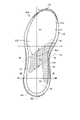
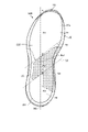
- FIG. 1 is a perspective view of a shoe according to the first embodiment of the present invention.
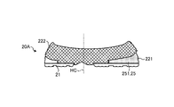
- FIG. 2 is a side view of the outer foot side of the shoe sole according to the first embodiment.
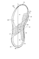
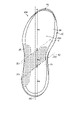
- FIG. 3 is a top view of the sole according to the first embodiment.
- FIG. 4 is a side view of the inner foot side of the shoe sole according to the first embodiment.
- FIG. 5 is a cross-sectional view of the sole according to the first embodiment.
- FIG. 6 is a cross-sectional view of the sole according to the first embodiment.
- FIG. 7 is a cross-sectional view of the sole according to the first embodiment.
- FIG. 8 is a cross-sectional view of the sole according to the first embodiment.
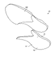
- FIG. 9 is an exploded perspective view of the midsole of the sole according to the first embodiment.
- FIG. 10 is a diagram showing the positional relationship between the sole of the shoe and the bone of the wearer's foot according to the first embodiment.
- FIG. 11 is a top view of the sole according to the first modification of the first embodiment.
- FIG. 12 is a top view of the sole according to the second modification of the first embodiment.
- FIG. 13 is a top view of the sole according to the third modification of the first embodiment.
- FIG. 14 is a top view of the sole according to the fourth modification of the first embodiment.
- FIG. 15 is a top view of the sole according to the fifth modification of the first embodiment.
- FIG. 16 is a cross-sectional view of a shoe sole according to a sixth modification of the first embodiment.
- FIG. 17 is a cross-sectional view of a shoe sole according to a sixth modification of the first embodiment.
- FIG. 18 is a cross-sectional view of a shoe sole according to a seventh modification of the first embodiment.
- FIG. 19 is a cross-sectional view of a shoe sole according to a seventh modification of the first embodiment.
- FIG. 20 is a side view of the inner foot side of the shoe sole according to the eighth modification of the first embodiment.
- FIG. 21 is a top view of the sole according to the ninth modification of the first embodiment.
- FIG. 22 is a top view of the sole according to another configuration of the ninth modification of the first embodiment.
- FIG. 23 is a top view of the sole according to another configuration of the ninth modification of the first embodiment.
- FIG. 24 is a top view of the shoe sole according to the second embodiment.
- FIG. 25 is a side view of the outer foot side of the shoe sole according to the second embodiment.
- the direction in which the heel center axis, which is a vertical line passing through the center of the heel of the sole in a plan view of the shoe, extends is referred to as an anteroposterior direction, and the anteroposterior direction in a plan view of the shoe.
- the direction orthogonal to the foot width direction is called the foot width direction.
- the direction from the end on the side where the part supporting the hind foot of the shoe sole is located to the end on the side where the part supporting the forefoot of the shoe sole is located is the front.
- the direction from the end on the side where the part supporting the forefoot part of the shoe sole is located to the end on the side where the part supporting the hindfoot part of the shoe sole is located is called the rear.
- the median side of the foot in the anatomical position is referred to as the inner foot side
- the side of the foot opposite to the median side in the anatomical position is referred to as the outer foot side. That is, the side near the midline in the anatomical position is referred to as the inner foot side, and the side far from the midline in the anatomical position is referred to as the outer foot side.
- the line connecting the position corresponding to 55% is set as the first boundary line, and the position corresponding to 70% of the anteroposterior dimension of the shoe sole on the inner edge of the shoe sole and from the front end of the shoe sole and the outer foot edge of the shoe sole.
- the part located in front of the first boundary line is the part of the shoe sole.
- the part sandwiched between the first boundary line and the second boundary line is called the forefoot support part
- the part located behind the second boundary line is called the middle foot support part of the shoe sole
- the part located behind the second boundary line is the hindfoot of the shoe sole. It is called a support part.
- the forefoot support of the shoe sole corresponds to the part that supports the forefoot part of the foot of the wearer of the standard body shape
- the midfoot support part of the shoe sole corresponds to the midfoot part of the foot of the wearer of the standard body shape.
- the hindfoot support part of the shoe sole corresponds to the part that supports the hindfoot part of the foot of a wearer of a standard body shape. That is, the first boundary line is a line substantially along the Lisfranc joint of the wearer of the standard body shape, and the second boundary line is a line substantially along the Chopard joint of the wearer of the standard body shape.
- the height direction means a direction orthogonal to both the front-back direction and the foot width direction unless otherwise specified, and the thickness means the height direction unless otherwise specified. Means the dimensions of.
- FIG. 1 is a perspective view of a shoe according to the first embodiment of the present invention.
- the shoe 1A includes an upper 10 and a sole 20A.
- the upper 10 has a shape that covers the entire instep side portion of the inserted foot.
- the sole 20A is located below the upper 10 and covers the sole of the foot.
- the upper 10 includes an upper body 11, a tongue 12, and a shoelace 16.
- the tongue 12 is fixed to the upper body 11.
- the upper body 11 is provided with an upper opening that exposes the upper part of the ankle and a part of the instep.
- a plurality of holes 13 are provided on the peripheral edge of the upper opening of the upper body 11.
- the tongue 12 is fixed to the upper body 11 by sewing, welding, adhesion, or a combination thereof so as to cover a portion of the upper opening provided in the upper body 11 that exposes a part of the instep.
- woven fabric, knitted fabric, synthetic leather or resin is used as the upper body 11 and the tongue 12.
- a double Russell warp knitted fabric in which polyester yarn is woven is used especially for shoes that are required to have breathability and light weight.
- the materials of the upper body 11 and the tongue 12 are not limited to the illustrated materials.
- the shoelace 16 is a string-shaped member, is inserted into a plurality of holes 13 of the upper body 11, and is detachably attached to the upper body 11.
- the shoelaces 16 inserted through the plurality of holes 13 draw the peripheral edges of the upper openings of the upper body 11 to each other in the foot width direction. By tightening the shoelace 16 with the foot inserted in the upper body 11, the upper body 11 can be brought into close contact with the foot.
- the upper 10 including the shoe tongue 12 and the shoe lace 16 will be described here as an example, the upper 10 may have a monosock structure in which the portion corresponding to the shoe tongue 12 is integrated with the ankle portion of the upper body 11. .. Further, in order to bring the upper body 11 into close contact with the foot, a hook-and-loop fastener may be used instead of the shoelace 16. When the upper body 11 is brought into close contact with the foot using a hook-and-loop fastener, the hole 13 is not formed in the upper body 11.
- the sole 20A is provided with an outsole 21 and a midsole 22.
- the lower surface of the outsole 21 is a ground contact surface 21b installed on the ground.
- the midsole 22 has a cushioning property and is located above the outsole 21.
- the outsole 21 may be integrated with the midsole 22.
- the midsole 22 with the outsole 21 integrated is also referred to as a "unisole".
- the shoe sole 20A has an insole (not shown) that covers the lower opening of the upper body 11.
- the insole is fixed to the upper surface 22a of the midsole 22 by adhesion or welding. Further, the insole is fixed to the lower edge of the upper body 11 described above by sewing.
- the shoe sole 20A may have a structure in which the insole is omitted.
- the shoe 1A may be provided with an insole.
- the insole is installed inside the upper 10 on the sole 20A.
- FIG. 2 is a side view of the outer foot side of the shoe sole according to the first embodiment.
- FIG. 3 is a top view of the sole according to the first embodiment.
- FIG. 4 is a side view of the inner foot side of the shoe sole according to the first embodiment.
- 5, FIG. 6, FIG. 7 and FIG. 8 are cross-sectional views of the sole according to the first embodiment.
- FIG. 5 shows a cross section along the VV line in FIG.
- FIG. 6 shows a cross section along the VI-VI line in FIG.
- FIG. 7 shows a cross section along the line VII-VII in FIG.
- FIG. 8 shows a cross section along line VIII-VIII in FIG.
- FIG. 9 is an exploded perspective view of the midsole of the sole according to the first embodiment.
- FIG. 10 is a diagram showing the positional relationship between the sole of the shoe according to the first embodiment and the bones of the foot of a wearer having a standard body shape.
- the sole 20A includes a cushion material portion 23 in addition to the above-mentioned outsole 21 and midsole 22.
- the outsole 21 has an upper surface 21a and a ground contact surface 21b in contact with the ground, and constitutes a lower portion of the sole 20A.
- the midsole 22 has an upper surface 22a and a lower surface 22b, and constitutes an upper portion of the sole 20A.
- the cushion material portion 23 is made of a non-foam material or a foam material of a polymer composition, and damps the impact at the time of landing during traveling.
- Examples of the polymer contained in the composition of the cushion material portion 23 include styrene-based polymers such as styrene-based elastomer and styrene-based resin, as well as olefin-based polymers, ester-based polymers, urethane-based polymers, and acrylic-based polymers. There is no limitation.
- the cushion material portion 23 is embedded in a portion of the midsole 22 on the outer foot side, and is sandwiched from above and below by the midsole 22 in the height direction.
- the outsole 21 is preferably excellent in wear resistance and grip. From the viewpoint of wear resistance and grip, the outsole 21 uses a member made of a material containing a rubber material as a main component and a sub-component. Auxiliary components are, for example, plasticizers, reinforcing agents and cross-linking agents. The material of the outsole 21 is not limited to the exemplified material.
- the outsole 21 is generally composed of a hard member having a higher Young's modulus than the midsole 22.
- the ground contact surface 21b of the outsole 21 is provided with a tread pattern by forming irregularities in order to improve grip.
- the shape and tread pattern of the outsole 21 are appropriately designed according to the use of the shoe 1A.
- the sole 20A is a forefoot support portion R1 that supports the forefoot portion of the foot of a wearer of a standard body shape, and a midfoot that supports the midfoot portion of the foot of a wearer of a standard body shape. It includes a support portion R2 and a hindfoot support portion R3 which is a portion that supports the hindfoot portion of the foot of a wearer of a standard body shape.
- the forefoot support portion R1, the middle foot support portion R2, and the hindfoot support portion R3 are connected in this order from the front of the sole 20A in the front-rear direction.
- the forefoot support portion R1 is located in front of the first boundary line S1.
- the midfoot support portion R2 is located at a portion sandwiched between the first boundary line S1 and the second boundary line S2.
- the hind foot support portion R3 is located behind the second boundary line S2.
- only the front part of the midfoot support portion R2 and the hindfoot support portion R3 is rolled upward on the inner foot side of the outsole 21 to form the side surface reinforcing portion 21f.
- the side reinforcing portion 21f is not formed in the front-side portion of the forefoot support portion R1 and the hindfoot support portion R3.
- the midsole 22 is generally composed of a soft member having a smaller Young's modulus than the outsole 21.
- the upper surface 22a of the midsole 22 has a shape in which the peripheral edge portion is raised with respect to the central portion, whereby the upper surface 22a is provided with a concave portion.
- This concave portion is a portion for receiving the upper 10 and the insole, and the portion of the upper surface 22a that is the bottom surface of the concave portion has a smooth curved surface shape so as to fit the shape of the sole of the foot.
- the peripheral edge of the upper surface 22a on the inner foot side is provided with an inclination from the side edge of the inner foot to the intermediate position between the heel center axis HC and the side edge of the inner foot.
- the inclination of the upper surface 22a on the inner foot side is larger toward the peripheral edge.
- the upper surface 22a of the midsole 22 does not have to be inclined at the peripheral edge on the inner foot side.
- the midsole 22 includes a cushioning portion 24 formed of a first foam material and a twist suppressing portion 25 formed of a second foam material having a hardness higher than that of the first foam material. It has a first layer 221 and a second layer 222 made of a material having a hardness lower than that of the twist suppressing portion 25.
- the first layer 221 is integrally formed by joining the cushioning portion 24 and the twist suppressing portion 25 to each other.
- the midsole 22 is composed of only the second layer 222 over the entire height direction.
- the first layer 221 is provided on the middle foot support portion R2 and the hind foot support portion R3.
- the second layer 222 is arranged above the first layer 221. That is, in the midfoot support portion R2 and the hindfoot support portion R3, the midsole 22 has a laminated structure in which the first layer 221 and the second layer 222 are overlapped. As shown in FIG. 8, the cushion material portion 23 described above is embedded in the hind foot support portion R3 of the midsole 22 by being sandwiched between the first layer 221 and the second layer 222.
- the midsole 22 is required to have an appropriate strength and an excellent cushioning property.
- a resin foam material containing a resin material as a main component and a foaming agent and a cross-linking agent as subcomponents is used for the cushioning portion 24 of the midsole 22. Be done.
- a rubber foam material containing a rubber material as a main component and a plasticizer, a foaming agent, a reinforcing agent and a cross-linking agent as subcomponents may be used.
- the resin material examples include foams of a polyolefin resin, an ethylene-vinyl acetate (EVA), and a polyamide-based thermoplastic elastomer (Thermoplastic-Polyamide-Elastomer).
- EVA ethylene-vinyl acetate
- Elastoplastic-Polyamide-Elastomer polyamide-based thermoplastic elastomer
- Polyurethane can be exemplified as an example of a thermosetting resin.
- butadiene rubber can be exemplified.
- the cushioning portion 24 formed of the first foam material of the midsole 22 is greatly deformed by receiving a load and plays a role of absorbing the impact at the time of landing. ..
- the twist suppressing portion 25 formed of the second foam material in the midsole 22 plays a role of ensuring stability at the time of landing because the deformation is smaller than that of the cushioning portion 24.
- the twist suppressing portion 25 includes a first portion 251 extending in the front-rear direction on the inner foot side and a second portion 252 extending diagonally rearward from the first portion 251 toward the outer foot side.
- the first portion 251 forms a side surface on the inner foot side of the twist suppressing portion 25. Therefore, as shown in FIG. 6, in the portion of the midfoot support portion R2 and the portion of the hindfoot support portion R3 that is closer to the front, the first portion 251 of the twist suppressing portion 25 is provided by the side surface reinforcing portion 21f from the inner foot side. It is covered.
- the first portion 251 is arranged over the entire midfoot support portion R2 and a part of the hindfoot support portion R3 near the front.
- the first portion 251 is arranged so as to support at least the wearer's first metatarsal sole C1 from the lateral edge of the inner foot of the shoe sole 20A.
- the first portion 251 is located on the inner edge of the sole 20A and at a position corresponding to 40% of the anteroposterior dimension of the sole 20A from the front end FE of the sole 20A and on the inner sole of the sole 20A and the sole. It is arranged from the front end FE of 20A to a position corresponding to 85% of the dimension in the front-rear direction of the sole 20A.
- the first portion 251 may extend at least in the front-rear direction over the entire midfoot support portion R2, and may not extend to the hind foot support portion R3.
- the first portion 251 is provided with a width of 15% to 45% of the dimension in the foot width direction from the side edge of the inner foot.
- the first portion 251 has a dimension in the foot width direction of 25 mm.
- the dimension of the first portion 251 in the foot width direction is not limited to the illustrated value.
- the first portion 251 supports the wearer's midfoot portion from below on the inner foot side, thereby preventing the wearer's heel portion of the shoe 1A from trying to fall inward.
- the second portion 252 includes a portion supporting the first metatarsal bone proximal end B1 and a portion supporting the fifth metatarsal bone proximal end B5 of a wearer of a standard body shape. It extends in the tying direction and is located in the region supporting the second metatarsal floor C2, the third metatarsal floor C3, the fourth metatarsal floor C4, and the fifth metatarsal floor C5.
- the portion supporting the first metatarsal proximal end B1 of the wearer of the standard body shape is 48% of the dimension in the anteroposterior direction from the front end FE of the sole 20A, and the inner foot side end IE of the sole 20A.
- the portion supporting the fifth metatarsal proximal end B5 of the wearer of a standard body shape is 60% of the dimension in the anteroposterior direction from the front end FE of the sole 20A, and the inner foot side end IE of the sole 20A. It is a position corresponding to 80% of the dimension in the foot width direction.
- the second portion 252 is a first position corresponding to 54% of the dimension in the front-rear direction from the front end FE of the shoe sole 20A and 80% of the dimension in the foot width direction from the inner foot side end IE of the shoe sole 20A, the sole.
- a second position corresponding to 40% of the dimension in the front-rear direction from the front end FE of 20A and 32% of the dimension in the foot width direction from the inner foot side end IE of the sole 20A, in the front-rear direction from the front end FE of the shoe sole 20A.
- a third position corresponding to 60% of the dimension and 30% of the dimension in the width direction from the inner foot side end IE of the sole 20A and 72% of the dimension in the front-rear direction from the front end FE of the sole 20A, and the sole. It is provided in the area corresponding to the range surrounded by the line connecting the fourth position corresponding to 75% of the dimension in the foot width direction from the inner foot side end IE of 20A.
- the size of the second part 252 in the anterior-posterior direction is set to about 53 mm, so that the second metatarsal sole C2 and the third of the wearer of a standard body shape can be used.
- the metatarsal bone C3, the fourth metatarsal bone C4 and the fifth metatarsal bone base C5 can be supported.
- the second portion 252 supports the second metatarsal bone sole C2 to the fifth metatarsal bone sole C5 of the wearer of the shoe 1A from below, thereby suppressing twisting of the shoe 1A during traveling.
- the second part 252 may be arranged in a region supporting at least the second metatarsal base C2 to the fourth metatarsal base C4 of a wearer having a standard body shape, and the fifth metatarsal bone may be provided. It does not have to be arranged in the region supporting the bottom C5.
- the second portion 252 may be provided in a range narrower than the range shown above in the front-rear direction.
- a plurality of rib-shaped protrusions 26 are formed on the inner foot side surface of the twist suppressing portion 25.
- Each of the plurality of rib-shaped protrusions 26 extends from the upper rear to the lower front.
- the rib-shaped protrusion 26 plays a role of increasing the rigidity of the twist suppressing portion 25. Therefore, by providing the rib-shaped protrusion 26, the rigidity of the twist suppressing portion 25 can be increased without increasing the hardness of the second foam material itself.
- the effect of increasing the rigidity of the twist suppressing portion 25 can be increased.
- the protrusion 26 extends.
- the effect of increasing the rigidity of the twist suppressing portion 25 can be obtained regardless of the orientation. That is, the direction in which the protrusion 26 extends is not limited to the direction from the upper rear to the lower front. It is not necessary that the rib-shaped protrusion 26 is formed on the inner foot side side surface of the twist suppressing portion 25.
- the second layer 222 is made of a material having a hardness lower than that of the twist suppressing portion 25, and plays a role of absorbing an impact at the time of landing. Since the sole 20A has the second layer 222, it can absorb the impact at the time of landing even in the portion where the twist suppressing portion 25 is arranged, so that the load on the wearer's foot can be reduced.
- the twist suppressing portion 25 has the first portion 251 it is possible to suppress overpronation in which the heel portion of the wearer falls inward more than necessary during traveling. That is, when a person who is prone to overpronation wears the shoe 1A, the sole of the foot can be stably supported by the first portion 251 in the portion on the inner foot side. Further, since the first portion 251 is arranged over the entire midfoot support portion R2 and a part of the hindfoot support portion R3 toward the front, the midsole 22 has the sole flexion of the foot in the kicking phase. Can be deformed according to.
- the shoe 1A provided with the sole 20A can stably support the inner foot side portion of the sole of the wearer without reducing the foot slippage.
- the ratio of the thickness of the first layer 221 to the thickness of the second layer 222 is arbitrary in the portion of the midsole 22 where the first layer 221 and the second layer 222 overlap. That is, the first layer 221 and the second layer 222 may have the same thickness, the first layer 221 may be thicker than the second layer 222, and the first layer 221 may be thicker than the second layer 222. May be thin. If the thickness of the midsole 22 is the same, the thicker the first layer 221 is, the thicker the twist suppressing portion 25 is, so that the effect of suppressing overpronation and suppressing twisting is higher, and the second layer 222 is thicker. Indeed, the cushioning performance is high.
- the twist suppressing portion 25 formed of the second foam material is porous, it is easily crushed by a compressive force, but exhibits high rigidity with respect to a tensile force. Therefore, by arranging the second layer 222 on the first layer 221 in the middle foot support portion R2 and the hind foot support portion R3, when the shoe 1A is twisted and the sole 20A is deformed, the entire twist suppressing portion 25 is covered. A tensile force can be applied, and the effect of suppressing twisting by the second portion 252 can be enhanced.
- the twist suppressing effect can be enhanced even if a part of the inner foot side wall surface of the twist suppressing portion 25 is covered with the other member. .. Further, even when another member is arranged between the midsole 22 and the outsole 21, the twist suppressing effect can be enhanced even if a part of the inner foot side wall surface of the twist suppressing portion 25 is covered with the other member. ..
- the shoe sole 20A and the shoe 1A provided with the sole 20A according to the first embodiment can adjust the degree of collapse of the heel portion and can be deformed following the sole bending of the foot.
- the hardness of the cushioning portion 24 of the midsole 22 is preferably 20 degrees or more and 70 degrees or less, and 40 degrees or more and 60 degrees or less in the type E durometer hardness measured by a JIS K 6253-3 type E durometer. Is more preferable.
- the hardness of the twist suppressing portion 25 is preferably 50 degrees or more and 85 degrees or less, provided that the type E durometer hardness is higher than the type E durometer hardness of the buffer portion 24.
- the difference between the type E durometer hardness of the twist suppressing portion 25 and the type E durometer hardness of the cushioning portion 24 is preferably 8 degrees or more, and more preferably 10 degrees or more.
- the sole 20A according to the first embodiment includes a first layer 221 in which the cushioning portion 24 and the twist suppressing portion 25 are joined to each other and integrated as described above.
- a first layer 221 in which the cushioning portion 24 and the twist suppressing portion 25 are joined to each other and integrated as described above.
- Such a configuration can be manufactured by superimposing a foam material serving as a cushioning portion 24 and a foam material serving as a twist suppressing portion 25 and welding them by press molding. Therefore, if the manufacturing method by press molding is used, the sole 20A provided with the first layer 221 having the cushioning portion 24 and the twist suppressing portion 25 can be easily and inexpensively manufactured.
- the foam material to be the cushioning portion 24 and the foam material to be the twist suppressing portion 25 may be injection-foamed at the same time and then placed in the same mold for press molding.
- the foam material and the foam material to be the twist suppressing portion 25 may be separately injection-foamed and then placed in the same mold for press molding.
- the foam material to be the cushioning portion 24 and the foam material to be the twist suppressing portion 25 are injection-foamed at the same time, it is possible to suppress an increase in the number of molds and work man-hours, reduce the manufacturing cost and improve the production efficiency. can.
- the foam material to be the cushioning portion 24 and the foam material to be the twist suppressing portion 25 are separately injection-foamed, the boundary between the cushioning portion 24 and the twist suppressing portion 25 becomes clear, so that twisting is suppressed at a desired position.
- the portion 25 can be reliably arranged.
- the sole 20A may be manufactured by forming the first layer 221.
- the twist suppressing portion 25 may be formed of a low hardness non-foaming material.
- the first portion 251 may be formed of a non-foaming material having a low hardness.
- the second portion 252 may be formed of a non-foaming material having a low hardness.
- the low hardness non-foaming material preferably has a type A durometer hardness of 70 degrees or less as measured by a type A durometer of JIS K6253-3. Examples of low-hardness non-foaming materials include EVA sheets, low-hardness thermosetting polyurethanes and rubbers, but are not limited to these materials.
- the pronation suppressing effect and the twist suppressing effect can be enhanced as compared with forming the entire twist suppressing portion 25 with a foam material.
- an EVA sheet or low-hardness thermosetting polyurethane is used as a material for at least a part of the twist suppressing portion 25, these parts are placed in a mold for forming the foam material and press-molded together with the foam material.
- the foam material and the non-foaming material can be integrated into one component, and the increase in the number of components can suppress the increase in work man-hours in the manufacturing process of the shoe 1A.
- FIG. 11 is a top view of the sole according to the first modification of the first embodiment.
- the sole 20B according to the first modification is an embodiment in which the first portion 251 of the twist suppressing portion 25 extends to the rear of the heel bone E of the wearer of the standard body shape shown in FIG. It is different from the sole 20A according to 1.
- the first portion 251 extends to the rear of the calcaneus E so as to avoid directly below the center of the calcaneus E and reaches the posterior end of the hind foot support portion R3.
- the portion directly below the calcaneus E is located at a position corresponding to 85% of the dimension in the anteroposterior direction from the front end FE of the sole 20B and 50% of the dimension in the foot width direction from the inner foot side end IE of the sole 20B. Is.
- the sole 20B according to the first modification is used in place of the sole 20A according to the first embodiment to form the shoe 1A.
- the shoe 1A constructed by using the sole 20B has an effect of suppressing the occurrence of overpronation in the heel landing phase because the first portion 251 extends to the rear of the heel bone E of the wearer of a standard body shape. However, it is higher than the shoe 1A configured by using the sole 20A.
- the first part 251 of the shoe sole 20B is not arranged directly under the center of the heel bone E, it is possible to prevent the impact from being directly transmitted to the wearer's foot during the heel landing phase.
- FIG. 12 is a top view of the sole according to the second modification of the first embodiment.
- the first portion 251 of the twist suppressing portion 25 extends forward to the extent that the first metatarsal body D1 of the wearer of the standard body shape shown in FIG. 10 is supported. In that respect, it is different from the sole 20A according to the first embodiment.
- the portion supporting the first metatarsal body D1 of the wearer of the standard body shape is 20% of the dimension in the anteroposterior direction from the front end FE of the sole 20C, and the foot from the inner foot side end IE of the sole 20C. It is a position corresponding to 30% of the dimension in the width direction.
- the second portion 252 of the twist suppressing portion 25 is provided in the same portion as the sole 20A according to the first embodiment. Therefore, in the shoe sole 20C according to the second modification, the twist suppressing portion 25 extends diagonally rearward from the intermediate portion of the first portion 251 to the second portion 252.
- the sole 20C according to the second modification is used in place of the sole 20A according to the first embodiment to form the shoe 1A.
- the shoe 1A constructed using the sole 20C has an overpronation in the kicking phase because the first portion 251 extends to the extent that it supports the first metatarsal body D1 of the wearer of the standard body shape.
- the effect of suppressing the occurrence of the above is higher than that of the shoe 1A configured by using the sole 20A.
- FIG. 13 is a top view of the sole according to the third modification of the first embodiment.
- the sole 20D according to the third modification is different from the sole 20A according to the first embodiment in that the width of the first portion 251 of the twist suppressing portion 25 is widened.
- the widened first portion 251 supports the second metatarsal bone C2 in addition to the first metatarsal bone base C1 of the standard wearer's foot shown in FIG.
- the first portion 251 is provided with a width of 15% to 45% of the dimension in the foot width direction from the inner foot side edge of the sole 20D.
- the sole 20D according to the third modification is used in place of the sole 20A according to the first embodiment to form the shoe 1A.
- the first portion 251 also supports the second metatarsal sole C2
- the effect of suppressing the occurrence of overpronation was configured by using the shoe sole 20A. It will be higher than shoes 1A. Therefore, when a person with a strong degree of overpronation runs, the load on the wearer's foot can be further reduced by wearing the shoe 1A configured by using the sole 20D.
- FIG. 14 is a top view of the sole according to the fourth modification of the first embodiment.
- the shoe sole 20E according to the fourth modification extends forward to the extent that the first portion 251 of the twist suppressing portion 25 supports the first metatarsal bone body D1 of the standard wearer's foot shown in FIG.
- the second part 252 is extended to the extent that it supports the second metatarsal body D2, the third metatarsal body D3, the fourth metatarsal body D4, and the fifth metatarsal body D5. Therefore, it is different from the shoe sole 20A according to the first embodiment.
- the part supporting the second metatarsal body D2 of the wearer of the standard body shape is 32% of the dimension in the anteroposterior direction from the front end FE of the sole 20E, and the foot from the inner foot side end IE of the sole 20E. It is a position corresponding to 41% of the dimension in the width direction.
- the portion supporting the third metatarsal body D3 of the wearer of the standard body shape is 35% of the dimension in the anteroposterior direction from the front end FE of the sole 20E, and the foot from the inner foot side end IE of the sole 20E. It is a position corresponding to 57% of the dimension in the width direction.
- the portion supporting the fourth metatarsal body D4 of the wearer of the standard body shape is 37% of the dimension in the anteroposterior direction from the front end FE of the sole 20E, and the foot from the inner foot side end IE of the sole 20E. It is a position corresponding to 70% of the dimension in the width direction.
- the portion supporting the fifth metatarsal body D5 of the wearer of the standard body shape is 39% of the dimension in the anteroposterior direction from the front end FE of the sole 20E, and the foot from the inner foot side end IE of the sole 20E. It is a position corresponding to 83% of the dimension in the width direction.
- the leading edge of the second portion 252 is located at the portion supporting the second middle bone body D2 of the wearer of the standard body shape shown in FIG.
- the first portion 251 is arranged from the front end FE of the sole 20E to the position corresponding to 69% from the position corresponding to 32% of the dimension in the front-rear direction of the sole 20E. Further, the first portion 251 is provided with a width of 15% to 45% of the dimension in the foot width direction from the side edge of the inner foot.
- the second portion 252 is a first position corresponding to 41% of the dimension in the front-rear direction from the front end FE of the shoe sole 20E and 83% of the dimension in the foot width direction from the inner foot side end IE of the shoe sole 20E.
- the second portion 252 extends diagonally rearward from the tip portion of the first portion 251.
- the sole 20E according to the fourth modification is used in place of the sole 20A according to the first embodiment to form the shoe 1A.
- the first portion 251 of the twist suppressing portion 25 extends forward to the range supporting the first metatarsal bone body D1, and the second portion 252 is the second portion. Since the metatarsal body D2, the third metatarsal body D3, the fourth metatarsal body D4, and the fifth metatarsal body D5 are extended to the extent that they are supported, the torsional rigidity of the metatarsal support portion R2 is shoe. It is higher than the shoe 1A configured with the sole 20A. Therefore, it is possible to prevent the shoe 1A from being twisted during traveling and the effect of suppressing overpronation is reduced.
- FIG. 15 is a top view of the sole according to the fifth modification of the first embodiment.
- the sole 20F according to the fifth modification is widened so that the trailing edge of the second portion 252 is located on the heel center axis HC so as to be located at the portion supporting the wearer's calcaneus E, and the second portion 252. Is different from the sole 20A according to the first embodiment in that it supports a part of the anterior surface of the calcaneus E.
- the trailing edge on the heel center axis HC is located at the anterior end of the talus F of the wearer of the standard body shape shown in FIG.
- the position of the front end portion of the talus F on the heel center axis HC is a position corresponding to 75% of the dimension in the anteroposterior direction from the center of the heel to the sole 20F.
- the second portion 252 is a first position corresponding to 54% of the dimension in the front-rear direction from the front end FE of the shoe sole 20F and 80% of the dimension in the foot width direction from the inner foot side end IE of the shoe sole 20F.
- a second position corresponding to 40% of the dimension in the front-rear direction from the front end FE of the sole 20F and 32% of the dimension in the foot width direction from the inner foot side end IE of the shoe sole 20F, front and back from the front end FE of the shoe sole 20F.
- the sole 20F according to the fifth modification is used in place of the sole 20A according to the first embodiment to form the shoe 1A.
- the second portion 252 is expanded so that the second portion 252 supports a part of the front part of the calcaneus E, the torsional rigidity of the midfoot support portion R2 Is higher than the shoe 1A configured with the sole 20A. Therefore, it is possible to prevent the shoe 1A from being twisted during traveling and the effect of suppressing overpronation is reduced. Since the second portion 252 is not arranged directly below the center of the talus F, the impact is not directly transmitted to the foot of the wearer of the shoe 1A configured by using the sole 20F in the heel landing phase. ..
- (6th modification) 16 and 17 are cross-sectional views of the sole according to the sixth modification of the first embodiment.
- the cross section of the shoe sole 20G according to the sixth modification shown in FIG. 16 is a cross section at a position corresponding to the position indicated by the VI-VI line of the shoe sole 20A according to the first embodiment.
- the cross section of the shoe sole 20G according to the sixth modification shown in FIG. 17 is a cross section at a position corresponding to the position indicated by the line VII-VII of the shoe sole 20A according to the first embodiment.
- the shoe sole 20G according to the sixth modification is according to the first embodiment in that the second layer 222 is arranged under the first layer 221 in the middle foot support portion R2 and the hind foot support portion R3. It is different from the sole 20A.
- the arrangement of the first layer 221 and the second layer 222 in the middle foot support portion R2 and the hind foot support portion R3 is different from the sole 20A according to the first embodiment. It's the other way around.
- the sole 20G according to the sixth modification is used in place of the sole 20A according to the first embodiment to form the shoe 1A.
- the sole 20G In the heel landing phase, the sole 20G is deformed so as to be convex downward. Therefore, in the sole 20G in which the first layer 221 is arranged on the upper side of the second layer 222, a compressive force acts on the twist suppressing portion 25 formed of the second foam material. As described above, the twist suppressing portion 25 formed of the second foam material exhibits high rigidity against a tensile force because it is porous, but is easily crushed by a compressive force. Therefore, in the sole 20G according to the sixth modification, the twist suppressing portion 25 can be provided with a function of absorbing the impact in the heel landing phase, and the impact absorption performance is higher than that of the sole 20A according to the first embodiment. Can be enhanced.
- the shoe sole 20G according to the sixth modification has a structure in which the twist suppressing portion 25 is easily deformed by arranging the first layer 221 on the upper side of the second layer 222, and thus according to the first embodiment. It is preferable that the hardness of the second foam material is higher than that of the sole 20A.
- the interface between the first layer 221 and the second layer 222 is a flat surface, but may be a curved surface similar to the upper surface 22a of the midsole 22.
- the seventh modification 18 and 19 are cross-sectional views of the sole according to the seventh modification of the first embodiment.
- the cross section of the shoe sole 20H according to the seventh modification shown in FIG. 18 is a cross section at a position corresponding to the position indicated by the VI-VI line of the shoe sole 20A according to the first embodiment.
- the cross section of the shoe sole 20H according to the seventh modification shown in FIG. 19 is a cross section at a position corresponding to the position indicated by the line VII-VII of the shoe sole 20A according to the first embodiment.
- the sole 20H according to the seventh modification is the sole 20A according to the first embodiment in that the entire midsole 22 is formed by the first layer 221 composed of the cushioning portion 24 and the twist suppressing portion 25. Is different from.
- the sole 20H according to the seventh modification is used in place of the sole 20A according to the first embodiment to form the shoe 1A.
- the entire midsole 22 of the shoe 1A configured by using the sole 20H is formed by the first layer 221, the number of parts is smaller than that of the shoe 1A using the sole 20A according to the first embodiment. .. Therefore, by constructing the shoe 1A using the sole 20H, the manufacturing efficiency of the shoe 1A can be improved.
- FIG. 20 is a side view of the inner foot side of the shoe sole according to the eighth modification of the first embodiment.
- the sole 20I according to the eighth modification is different from the sole 20A according to the first embodiment in that a groove-shaped recess 27 is provided on the inner foot side side surface of the twist suppressing portion 25.
- the sole 20I according to the eighth modification is used in place of the sole 20A according to the first embodiment to form the shoe 1A.
- the shoe 1A configured by using the sole 20I has a plurality of groove-shaped recesses 27 formed on the inner foot side side surface of the twist suppressing portion 25.
- Each of the plurality of groove-shaped recesses 27 extends from the lower rear to the upper front.
- the groove-shaped recess 27 serves to reduce the rigidity of the twist suppressing portion 25. Therefore, by providing the groove-shaped recess 27, the rigidity of the twist suppressing portion 25 can be reduced without lowering the hardness of the second foam material itself.
- the effect of reducing the rigidity of the twist suppressing portion 25 can be increased.
- the recess 27 The effect of reducing the rigidity of the twist suppressing portion 25 can be obtained regardless of the extending direction. That is, the direction in which the recess 27 extends is not limited to the direction from the lower rear to the upper front.
- FIG. 21 is a top view of the sole according to the ninth modification of the first embodiment.
- the sole 20J according to the ninth modification is different from the sole 20A according to the first embodiment in that a narrowed portion 28 having a partially small size in the front-rear direction is formed in the second portion 252.
- the sole 20J according to the ninth modification is used in place of the sole 20A according to the first embodiment to form the shoe 1A.
- the rigidity of the second portion 252 is lower than that of the shoe sole 20A according to the first embodiment. That is, by providing the narrowed portion 28 in the second portion 252, the rigidity of the second portion 252 can be adjusted without changing the type of the second foam material used as the material of the twist suppressing portion 25.
- the shoe 1A configured by using the sole 20J is deformed according to the sole flexion of the wearer's foot because the narrowed portion 28 is provided in the second portion 252 and the rigidity of the second portion 252 is low. It's easy to do.
- FIG. 22 and 23 are top views of the sole according to another configuration of the ninth modification of the first embodiment.
- a notch was formed from the front at the boundary portion of the second portion 252 with the first portion 251 to provide the narrowed portion 28, but as shown in FIG. 22, A notch may be formed from the rear at the boundary portion of the second portion 252 with the first portion 251 to provide the narrowed portion 28.
- the narrowed portion 28 may be provided in the portion on the outer leg side of the second portion 252.
- the portion where the second portion 252 is cut out is covered with the outsole 21.
- FIG. 24 is a top view of the shoe sole according to the second embodiment.
- FIG. 25 is a side view of the outer foot side of the shoe sole according to the second embodiment.
- the first portion 251 of the twist suppressing portion 25 is provided on the outer foot side, and the second portion 252 extends diagonally forward from the first portion 251. It is different from the sole 20A according to the first embodiment.
- the sole 20K according to the second embodiment is used in place of the sole 20A according to the first embodiment to form the shoe 1A.
- the first portion 251 supports the wearer's midfoot portion from below on the outer foot side, thereby preventing the wearer's heel portion of the shoe 1A from falling outward. Further, the second portion 252 supports the metatarsal bone sole of the wearer of the shoe 1A from below, thereby suppressing twisting of the shoe 1A during running.
- the first portion 251 is arranged over a part of the forefoot support portion R1 that is closer to the rear, the entire middle foot support portion R2, and a part of the hindfoot support portion R3 that is closer to the front.
- the first portion 251 is arranged from the front end FE of the sole 20K to the position corresponding to 90% from the position corresponding to 40% of the dimension in the front-rear direction of the sole 20K.
- the first portion 251 may extend at least in the front-rear direction over the entire midfoot support portion R2, and may not extend to the forefoot support portion R1 and the hindfoot support portion R3.
- the first portion 251 is provided with a width of 15% to 45% of the dimension in the foot width direction from the lateral edge of the outer foot.
- the first portion 251 has a dimension in the foot width direction of 25 mm.
- the dimension of the first portion 251 in the foot width direction is not limited to the illustrated value.
- the second portion 252 includes a portion supporting the first metatarsal bone proximal end B1 and the fifth metatarsal bone proximal end B5 of the wearer of the standard body shape shown in FIG. It extends in the direction connecting the supporting portion and is arranged in the region supporting the 4th metatarsal floor C4, the 3rd metatarsal floor C3, the 2nd metatarsal floor C2 and the 1st metatarsal floor C1. ..
- the second portion 252 is a first position corresponding to 52% of the dimension in the front-rear direction from the front end FE of the sole 20K and 65% of the dimension in the foot width direction from the inner foot side end IE of the sole 20K.
- the inner foot sinks more than the wearer's outer foot from the heel landing phase to the kicking phase. It becomes easy to get in. Therefore, by wearing the shoe 1A configured by using the sole 20K, it is possible to suppress the occurrence of underpronation during traveling.
- the configuration shown in the above-described embodiment shows an example of the content of the present invention, can be combined with another known technique, and is one of the configurations as long as it does not deviate from the gist of the present invention. It is also possible to omit or change the part.
- the characteristic configurations shown in the first embodiment and its modifications can be combined with each other.
Landscapes
- Chemical & Material Sciences (AREA)
- Engineering & Computer Science (AREA)
- Materials Engineering (AREA)
- Health & Medical Sciences (AREA)
- Epidemiology (AREA)
- General Health & Medical Sciences (AREA)
- Public Health (AREA)
- Footwear And Its Accessory, Manufacturing Method And Apparatuses (AREA)
Abstract
Description
図1は、本発明の実施の形態1に係る靴の斜視図である。靴1Aは、アッパー10と、靴底20Aとを備えている。アッパー10は、挿入された足の甲側の部分の全体を覆う形状を有している。靴底20Aは、アッパー10の下方に位置し足裏を覆う。
図11は、実施の形態1の第1変形例に係る靴底の上面図である。第1変形例に係る靴底20Bは、ねじれ抑制部25の第1部分251が、図10に示した標準的な体型の着用者の踵骨Eの後方まで延びている点で、実施の形態1に係る靴底20Aと相違する。第1部分251は、踵骨Eの中心の直下を避けて回り込むようにして踵骨Eの後方まで延伸され、後足支持部R3の後端まで達している。なお、踵骨Eの直下となる部分は、靴底20Bの前端FEから前後方向の寸法の85%、かつ靴底20Bの内足側端IEから足幅方向の寸法の50%に相当する位置である。第1変形例に係る靴底20Bは、実施の形態1に係る靴底20Aの代わりに用いられて、靴1Aを構成する。
図12は、実施の形態1の第2変形例に係る靴底の上面図である。第2変形例に係る靴底20Cは、ねじれ抑制部25の第1部分251が、図10に示した標準的な体型の着用者の第1中足骨体D1を支持する範囲まで前方に延びている点で、実施の形態1に係る靴底20Aと相違する。なお、標準的な体型の着用者の第1中足骨体D1を支持する部分は、靴底20Cの前端FEから前後方向の寸法の20%、かつ靴底20Cの内足側端IEから足幅方向の寸法の30%に相当する位置である。ねじれ抑制部25の第2部分252は、実施の形態1に係る靴底20Aと同じ部分に設けられている。したがって、第2変形例に係る靴底20Cでは、ねじれ抑制部25は、第1部分251の中間部から第2部分252が斜め後方に延びている。第2変形例に係る靴底20Cは、実施の形態1に係る靴底20Aの代わりに用いられて、靴1Aを構成する。
図13は、実施の形態1の第3変形例に係る靴底の上面図である。第3変形例に係る靴底20Dは、ねじれ抑制部25の第1部分251の幅が広げられている点で、実施の形態1に係る靴底20Aと相違する。幅が広げられた第1部分251は、図10に示した標準的な着用者の足の第1中足骨底C1に加え第2中足骨底C2も支持している。例えば、第1部分251は、靴底20Dの内足側縁から足幅方向の寸法の15%から45%の幅で設けられる。第3変形例に係る靴底20Dは、実施の形態1に係る靴底20Aの代わりに用いられて、靴1Aを構成する。
図14は、実施の形態1の第4変形例に係る靴底の上面図である。第4変形例に係る靴底20Eは、ねじれ抑制部25の第1部分251が、図10に示した標準的な着用者の足の第1中足骨体D1を支持する範囲まで前方に延びており、かつ第2部分252が第2中足骨体D2、第3中足骨体D3、第4中足骨体D4及び第5中足骨体D5を支持する範囲まで広げられている点で、実施の形態1に係る靴底20Aと相違する。なお、標準的な体型の着用者の第2中足骨体D2を支持する部分は、靴底20Eの前端FEから前後方向の寸法の32%、かつ靴底20Eの内足側端IEから足幅方向の寸法の41%に相当する位置である。また、標準的な体型の着用者の第3中足骨体D3を支持する部分は、靴底20Eの前端FEから前後方向の寸法の35%、かつ靴底20Eの内足側端IEから足幅方向の寸法の57%に相当する位置である。また、標準的な体型の着用者の第4中足骨体D4を支持する部分は、靴底20Eの前端FEから前後方向の寸法の37%、かつ靴底20Eの内足側端IEから足幅方向の寸法の70%に相当する位置である。また、標準的な体型の着用者の第5中足骨体D5を支持する部分は、靴底20Eの前端FEから前後方向の寸法の39%、かつ靴底20Eの内足側端IEから足幅方向の寸法の83%に相当する位置である。靴底20Eにおいて、第2部分252の前縁は、図10に示した標準的な体型の着用者の第2中骨体D2を支持する部分に位置している。例えば、第1部分251は、靴底20Eの前端FEから靴底20Eの前後方向の寸法の32%に相当する位置から69%に相当する位置にわたって配置されている。また、第1部分251は、内足側縁から足幅方向の寸法の15%から45%の幅で設けられる。また、第2部分252は、靴底20Eの前端FEから前後方向の寸法の41%、かつ靴底20Eの内足側端IEから足幅方向の寸法の83%に相当する第1の位置、靴底20Eの前端FEから前後方向の寸法の31%、かつ靴底20Eの内足側端IEから足幅方向の寸法の32%に相当する第2の位置、靴底20Eの前端FEから前後方向の寸法の60%、かつ靴底20Eの内足側端IEから足幅方向の寸法の30%に相当する第3の位置及び靴底20Eの前端FEから前後方向の寸法の72%、かつ靴底20Eの内足側端IEから足幅方向の寸法の75%に相当する第4の位置を繋いだ線によって囲まれる範囲に相当する領域に設けられている。第4変形例に係る靴底20Eは、第1部分251の先端部から第2部分252が斜め後方に延びている。第4変形例に係る靴底20Eは、実施の形態1に係る靴底20Aの代わりに用いられて、靴1Aを構成する。
図15は、実施の形態1の第5変形例に係る靴底の上面図である。第5変形例に係る靴底20Fは、ヒールセンター軸HC上で第2部分252の後縁が、着用者の踵骨Eを支持する部分に位置するように広げられており、第2部分252が踵骨Eの前方の一部を支持する点で、実施の形態1に係る靴底20Aと相違する。例えば、第2部分252は、ヒールセンター軸HC上での後縁が、図10に示した標準的な体型の着用者の距骨Fの前端部に位置している。なお、ヒールセンター軸HC上での距骨Fの前端部の位置は、踵中心から靴底20Fの前後方向の寸法の75%に相当する位置である。また、第2部分252は、靴底20Fの前端FEから前後方向の寸法の54%、かつ靴底20Fの内足側端IEから足幅方向の寸法の80%に相当する第1の位置、靴底20Fの前端FEから前後方向の寸法の40%、かつ靴底20Fの内足側端IEから足幅方向の寸法の32%に相当する第2の位置、靴底20Fの前端FEから前後方向の寸法の70%、かつ靴底20Fの内足側端IEから足幅方向の寸法の30%に相当する第3の位置及び靴底20Fの前端FEから前後方向の寸法の84%、かつ靴底20Fの内足側端IEから足幅方向の寸法の80%に相当する第4の位置を繋いだ線によって囲まれる範囲に相当する領域に設けられている。第5変形例に係る靴底20Fは、実施の形態1に係る靴底20Aの代わりに用いられて、靴1Aを構成する。
図16及び図17は、実施の形態1の第6変形例に係る靴底の断面図である。図16に示す第6変形例に係る靴底20Gの断面は、実施の形態1に係る靴底20AのVI-VI線が示す位置に相当する位置での断面である。また、図17に示す第6変形例に係る靴底20Gの断面は、実施の形態1に係る靴底20AのVII-VII線が示す位置に相当する位置での断面である。第6変形例に係る靴底20Gは、中足支持部R2及び後足支持部R3において、第1層221の下側に第2層222が配置されている点で、実施の形態1に係る靴底20Aと相違する。すなわち、第6変形例に係る靴底20Gは、中足支持部R2及び後足支持部R3における第1層221と第2層222との配置が、実施の形態1に係る靴底20Aとは逆になっている。第6変形例に係る靴底20Gは、実施の形態1に係る靴底20Aの代わりに用いられて、靴1Aを構成する。
図18及び図19は、実施の形態1の第7変形例に係る靴底の断面図である。図18に示す第7変形例に係る靴底20Hの断面は、実施の形態1に係る靴底20AのVI-VI線が示す位置に相当する位置での断面である。また、図19に示す第7変形例に係る靴底20Hの断面は、実施の形態1に係る靴底20AのVII-VII線が示す位置に相当する位置での断面である。第7変形例に係る靴底20Hは、ミッドソール22全体が緩衝部24とねじれ抑制部25とで構成された第1層221で形成されている点で、実施の形態1に係る靴底20Aと相違する。第7変形例に係る靴底20Hは、実施の形態1に係る靴底20Aの代わりに用いられて、靴1Aを構成する。
図20は、実施の形態1の第8変形例に係る靴底の内足側側面図である。第8変形例に係る靴底20Iは、ねじれ抑制部25の内足側側面に溝状の凹部27が設けられている点で、実施の形態1に係る靴底20Aと相違する。第8変形例に係る靴底20Iは、実施の形態1に係る靴底20Aの代わりに用いられて、靴1Aを構成する。
図21は、実施の形態1の第9変形例に係る靴底の上面図である。第9変形例に係る靴底20Jは、第2部分252に前後方向の寸法が部分的に小さい狭窄部28が形成されている点で、実施の形態1に係る靴底20Aと相違する。第9変形例に係る靴底20Jは、実施の形態1に係る靴底20Aの代わりに用いられて、靴1Aを構成する。
図24は、実施の形態2に係る靴底の上面図である。図25は、実施の形態2に係る靴底の外足側側面図である。実施の形態2に係る靴底20Kは、ねじれ抑制部25の第1部分251が外足側に設けられており、第2部分252が第1部分251から斜め前方に延びている点で実施の形態1に係る靴底20Aと相違する。実施の形態2に係る靴底20Kは、実施の形態1に係る靴底20Aの代わりに用いられて、靴1Aを構成する。
Claims (22)
- 着用者の足の前足部を支持する前足支持部、足の中足部を支持する中足支持部、及び足の後足部を支持する後足支持部が、この順で前方から連なった靴底であって、
クッション性を有するミッドソールを備え、
前記ミッドソールは、第1のフォーム材で形成された緩衝部と、第1のフォーム材よりも硬度が高い材料で形成されたねじれ抑制部と、を備え、
前記ねじれ抑制部は、内足側において前後方向に少なくとも前記中足支持部全体にわたって延びる第1部分と、前記第1部分から外足側に向かって斜め後方に延びる第2部分とを備える、靴底。 - 前記第2部分は、着用者の足の第1中足骨近位端を支持する部分と着用者の足の第5中足骨近位端を支持する部分とを結ぶ方向に延び、着用者の足の第2中足骨底から第5中足骨底までを支持する領域に配置されている、請求項1に記載の靴底。
- 前記第2部分の前縁は、着用者の足の第2中足骨体の前端を支持する部分に位置する、請求項2に記載の靴底。
- 前記第2部分は、ヒールセンター軸上での後縁が、着用者の踵骨を支持する部分に位置する、請求項2又は3に記載の靴底。
- 前記第1部分は、前記後足支持部まで後方に延びている、請求項1から4のいずれか1項に記載の靴底。
- 前記第1部分は、前記後足支持部の後端まで達している、請求項5に記載の靴底。
- 前記第1部分は、前記前足支持部まで前方に延び、着用者の足の第1中足骨体の前端を支持する部分まで達している、請求項1から6のいずれか1項に記載の靴底。
- 前記第1部分は、内足側縁から着用者の足の第2中足骨底を支持する部分にかけての幅で前後方向に延びている、請求項1から7のいずれか1項に記載の靴底。
- 前記ねじれ抑制部が、前記第1のフォーム材よりも硬度が高い第2のフォーム材で形成された、請求項1から8のいずれか1項に記載の靴底。
- 前記ねじれ抑制部は、少なくとも一部が、前記第1のフォーム材よりも硬度が高い非発泡樹脂材料で形成されている、請求項1から8のいずれか1項に記載の靴底。
- 前記ねじれ抑制部は、前記第1部分及び前記第2部分の少なくとも一方が、前記第1のフォーム材よりも硬度が高い非発泡樹脂材料で形成されている、請求項10に記載の靴底。
- 前記ミッドソールは、前記緩衝部及び前記ねじれ抑制部を備えた第1層と、前記ねじれ抑制部よりも硬度が低い材料で形成された第2層とが積層された構造である、請求項1から11のいずれか1項に記載の靴底。
- 前記第2層が、前記第1層の上方に位置する、請求項12に記載の靴底。
- 前記第2層が、前記第1層の下方に位置する、請求項12に記載の靴底。
- 前記第1部分は、内足側縁部の上面が、幅方向の中央に向かって下がるように傾斜している、請求項1から14のいずれか1項に記載の靴底。
- 前記ミッドソールの下方に設けられたアウトソールを備え、
前記ねじれ抑制部の内足側側面は、少なくとも一部が前記アウトソールによって覆われている、請求項1から15のいずれか1項に記載の靴底。 - 前記ねじれ抑制部は、内足側側面に複数のリブ状の突起が形成されている、請求項1から16のいずれか1項に記載の靴底。
- 前記リブ状の突起は、後方上方から前方下方に延びる、請求項17に記載の靴底。
- 前記ねじれ抑制部は、内足側側面に複数の溝状の凹部が形成されている、請求項1から16のいずれか1項に記載の靴底。
- 前記溝状の凹部は、後方下方から前方上方に延びる、請求項19に記載の靴底。
- 前記第2部分は、前後方向寸法が部分的に小さい狭窄部を備える、請求項1から20のいずれか1項に記載の靴底。
- 請求項1から21のいずれか1項に記載の靴底と、前記靴底の上方に位置するアッパーとを備えた、靴。
Priority Applications (4)
| Application Number | Priority Date | Filing Date | Title |
|---|---|---|---|
| PCT/JP2020/038386 WO2022074845A1 (ja) | 2020-10-09 | 2020-10-09 | 靴底及びこれを備えた靴 |
| EP20956792.4A EP4209145A4 (en) | 2020-10-09 | 2020-10-09 | SHOE SOLE AND SHOE INCLUDING SAME |
| US18/247,617 US20230380543A1 (en) | 2020-10-09 | 2020-10-09 | Sole and shoe including same |
| JP2022555248A JPWO2022074845A1 (ja) | 2020-10-09 | 2020-10-09 |
Applications Claiming Priority (1)
| Application Number | Priority Date | Filing Date | Title |
|---|---|---|---|
| PCT/JP2020/038386 WO2022074845A1 (ja) | 2020-10-09 | 2020-10-09 | 靴底及びこれを備えた靴 |
Publications (1)
| Publication Number | Publication Date |
|---|---|
| WO2022074845A1 true WO2022074845A1 (ja) | 2022-04-14 |
Family
ID=81125783
Family Applications (1)
| Application Number | Title | Priority Date | Filing Date |
|---|---|---|---|
| PCT/JP2020/038386 WO2022074845A1 (ja) | 2020-10-09 | 2020-10-09 | 靴底及びこれを備えた靴 |
Country Status (4)
| Country | Link |
|---|---|
| US (1) | US20230380543A1 (ja) |
| EP (1) | EP4209145A4 (ja) |
| JP (1) | JPWO2022074845A1 (ja) |
| WO (1) | WO2022074845A1 (ja) |
Cited By (1)
| Publication number | Priority date | Publication date | Assignee | Title |
|---|---|---|---|---|
| EP4268660A1 (en) * | 2022-04-28 | 2023-11-01 | ASICS Corporation | Sole of shoe and shoe |
Citations (5)
| Publication number | Priority date | Publication date | Assignee | Title |
|---|---|---|---|---|
| JPS64500491A (ja) * | 1986-06-04 | 1989-02-23 | ||
| JPH1142103A (ja) * | 1997-07-28 | 1999-02-16 | Mizuno Corp | スポーツシューズ用の靴底 |
| JP2000225002A (ja) | 1999-02-05 | 2000-08-15 | Adidas Internatl Bv | 靴 |
| JP2017000213A (ja) * | 2015-06-05 | 2017-01-05 | 美津濃株式会社 | シューズのソール構造体 |
| JP2020110631A (ja) * | 2015-03-23 | 2020-07-27 | アディダス アーゲー | ソールおよびシューズ |
Family Cites Families (3)
| Publication number | Priority date | Publication date | Assignee | Title |
|---|---|---|---|---|
| WO2007122722A1 (ja) * | 2006-04-21 | 2007-11-01 | Asics Corporation | 強化構造を備えた靴底および緩衝構造を備えた靴底 |
| DE102014107751A1 (de) * | 2014-06-03 | 2015-12-03 | Deeluxe Sportartikel Handels Gmbh | Schuh, insbesondere Laufschuh |
| GB2564307B (en) * | 2016-03-15 | 2021-09-29 | Nike Innovate Cv | Foam compositions and uses thereof |
-
2020
- 2020-10-09 JP JP2022555248A patent/JPWO2022074845A1/ja active Pending
- 2020-10-09 WO PCT/JP2020/038386 patent/WO2022074845A1/ja active Application Filing
- 2020-10-09 EP EP20956792.4A patent/EP4209145A4/en not_active Withdrawn
- 2020-10-09 US US18/247,617 patent/US20230380543A1/en active Pending
Patent Citations (5)
| Publication number | Priority date | Publication date | Assignee | Title |
|---|---|---|---|---|
| JPS64500491A (ja) * | 1986-06-04 | 1989-02-23 | ||
| JPH1142103A (ja) * | 1997-07-28 | 1999-02-16 | Mizuno Corp | スポーツシューズ用の靴底 |
| JP2000225002A (ja) | 1999-02-05 | 2000-08-15 | Adidas Internatl Bv | 靴 |
| JP2020110631A (ja) * | 2015-03-23 | 2020-07-27 | アディダス アーゲー | ソールおよびシューズ |
| JP2017000213A (ja) * | 2015-06-05 | 2017-01-05 | 美津濃株式会社 | シューズのソール構造体 |
Non-Patent Citations (1)
| Title |
|---|
| See also references of EP4209145A4 |
Cited By (1)
| Publication number | Priority date | Publication date | Assignee | Title |
|---|---|---|---|---|
| EP4268660A1 (en) * | 2022-04-28 | 2023-11-01 | ASICS Corporation | Sole of shoe and shoe |
Also Published As
| Publication number | Publication date |
|---|---|
| JPWO2022074845A1 (ja) | 2022-04-14 |
| EP4209145A4 (en) | 2023-10-04 |
| US20230380543A1 (en) | 2023-11-30 |
| EP4209145A1 (en) | 2023-07-12 |
Similar Documents
| Publication | Publication Date | Title |
|---|---|---|
| CN109068797B (zh) | 具有自适应配合的鞋类物品 | |
| JP7295622B2 (ja) | ソール構造およびそれを用いたシューズ | |
| JP5444528B2 (ja) | 歩行具 | |
| US8250784B2 (en) | Shoe insole | |
| JP5411988B2 (ja) | 靴のインソール | |
| US8099880B2 (en) | Athletic shoe with cushion structures | |
| KR101889494B1 (ko) | 보호 요소를 갖는 경량의 중창 부재를 구비하는 밑창 구조체 및 신발류 물품 | |
| KR20070049648A (ko) | 깔창 및 이것을 구비하는 풋웨어 시스템 | |
| JP2016530042A (ja) | トライアスロン用中敷き | |
| WO2010137068A1 (ja) | トレーニングに適した靴の靴底 | |
| JPH0431682B2 (ja) | ||
| US20200093219A1 (en) | Sole Structure and Shoe with the Sole Structure | |
| KR20240000341U (ko) | 넣고 빼기가 용이한 신발 카운터 | |
| JP7491725B2 (ja) | シューズ | |
| TW202300050A (zh) | 用於鞋類物件而於加強籠件中設有中足間隙和前足囊袋的鞋底結構 | |
| WO2021210045A1 (ja) | ソール及び履物 | |
| US20220225732A1 (en) | Shoe insole | |
| WO2022074845A1 (ja) | 靴底及びこれを備えた靴 | |
| JP2020039477A (ja) | シューズ | |
| KR20160135495A (ko) | 바른 보행, 관절 보호 및 피로 방지 구두용 중창 | |
| US20160286895A1 (en) | Footwear | |
| JP2021145686A (ja) | シューズ | |
| WO2021085574A1 (ja) | 靴の中敷き | |
| JP2005224335A (ja) | 矯正用靴 | |
| JP2022172486A (ja) | 靴の中敷き |
Legal Events
| Date | Code | Title | Description |
|---|---|---|---|
| 121 | Ep: the epo has been informed by wipo that ep was designated in this application |
Ref document number: 20956792 Country of ref document: EP Kind code of ref document: A1 |
|
| ENP | Entry into the national phase |
Ref document number: 2022555248 Country of ref document: JP Kind code of ref document: A |
|
| WWE | Wipo information: entry into national phase |
Ref document number: 18247617 Country of ref document: US |
|
| ENP | Entry into the national phase |
Ref document number: 2020956792 Country of ref document: EP Effective date: 20230406 |
|
| NENP | Non-entry into the national phase |
Ref country code: DE |