EP4268660B1 - Sohle für schuh und schuh - Google Patents
Sohle für schuh und schuh Download PDFInfo
- Publication number
- EP4268660B1 EP4268660B1 EP23170299.4A EP23170299A EP4268660B1 EP 4268660 B1 EP4268660 B1 EP 4268660B1 EP 23170299 A EP23170299 A EP 23170299A EP 4268660 B1 EP4268660 B1 EP 4268660B1
- Authority
- EP
- European Patent Office
- Prior art keywords
- foot
- midsole
- sole
- medial
- support portion
- Prior art date
- Legal status (The legal status is an assumption and is not a legal conclusion. Google has not performed a legal analysis and makes no representation as to the accuracy of the status listed.)
- Active
Links
Images


Classifications
-
- A—HUMAN NECESSITIES
- A43—FOOTWEAR
- A43B—CHARACTERISTIC FEATURES OF FOOTWEAR; PARTS OF FOOTWEAR
- A43B13/00—Soles; Sole-and-heel integral units
- A43B13/14—Soles; Sole-and-heel integral units characterised by the constructive form
-
- A—HUMAN NECESSITIES
- A43—FOOTWEAR
- A43B—CHARACTERISTIC FEATURES OF FOOTWEAR; PARTS OF FOOTWEAR
- A43B7/00—Footwear with health or hygienic arrangements
- A43B7/14—Footwear with health or hygienic arrangements with foot-supporting parts
- A43B7/1405—Footwear with health or hygienic arrangements with foot-supporting parts with pads or holes on one or more locations, or having an anatomical or curved form
- A43B7/1415—Footwear with health or hygienic arrangements with foot-supporting parts with pads or holes on one or more locations, or having an anatomical or curved form characterised by the location under the foot
- A43B7/142—Footwear with health or hygienic arrangements with foot-supporting parts with pads or holes on one or more locations, or having an anatomical or curved form characterised by the location under the foot situated under the medial arch, i.e. under the navicular or cuneiform bones
-
- A—HUMAN NECESSITIES
- A43—FOOTWEAR
- A43B—CHARACTERISTIC FEATURES OF FOOTWEAR; PARTS OF FOOTWEAR
- A43B13/00—Soles; Sole-and-heel integral units
- A43B13/02—Soles; Sole-and-heel integral units characterised by the material
- A43B13/12—Soles with several layers of different materials
- A43B13/125—Soles with several layers of different materials characterised by the midsole or middle layer
-
- A—HUMAN NECESSITIES
- A43—FOOTWEAR
- A43B—CHARACTERISTIC FEATURES OF FOOTWEAR; PARTS OF FOOTWEAR
- A43B13/00—Soles; Sole-and-heel integral units
- A43B13/14—Soles; Sole-and-heel integral units characterised by the constructive form
- A43B13/18—Resilient soles
- A43B13/181—Resiliency achieved by the structure of the sole
- A43B13/186—Differential cushioning region, e.g. cushioning located under the ball of the foot
-
- A—HUMAN NECESSITIES
- A43—FOOTWEAR
- A43B—CHARACTERISTIC FEATURES OF FOOTWEAR; PARTS OF FOOTWEAR
- A43B13/00—Soles; Sole-and-heel integral units
- A43B13/14—Soles; Sole-and-heel integral units characterised by the constructive form
- A43B13/18—Resilient soles
- A43B13/187—Resiliency achieved by the features of the material, e.g. foam, non liquid materials
- A43B13/188—Differential cushioning regions
-
- A—HUMAN NECESSITIES
- A43—FOOTWEAR
- A43B—CHARACTERISTIC FEATURES OF FOOTWEAR; PARTS OF FOOTWEAR
- A43B3/00—Footwear characterised by the shape or the use
-
- A—HUMAN NECESSITIES
- A43—FOOTWEAR
- A43B—CHARACTERISTIC FEATURES OF FOOTWEAR; PARTS OF FOOTWEAR
- A43B7/00—Footwear with health or hygienic arrangements
- A43B7/14—Footwear with health or hygienic arrangements with foot-supporting parts
- A43B7/1405—Footwear with health or hygienic arrangements with foot-supporting parts with pads or holes on one or more locations, or having an anatomical or curved form
- A43B7/1415—Footwear with health or hygienic arrangements with foot-supporting parts with pads or holes on one or more locations, or having an anatomical or curved form characterised by the location under the foot
- A43B7/1445—Footwear with health or hygienic arrangements with foot-supporting parts with pads or holes on one or more locations, or having an anatomical or curved form characterised by the location under the foot situated under the midfoot, i.e. the second, third or fourth metatarsal
-
- A—HUMAN NECESSITIES
- A43—FOOTWEAR
- A43B—CHARACTERISTIC FEATURES OF FOOTWEAR; PARTS OF FOOTWEAR
- A43B7/00—Footwear with health or hygienic arrangements
- A43B7/14—Footwear with health or hygienic arrangements with foot-supporting parts
- A43B7/1405—Footwear with health or hygienic arrangements with foot-supporting parts with pads or holes on one or more locations, or having an anatomical or curved form
- A43B7/1475—Footwear with health or hygienic arrangements with foot-supporting parts with pads or holes on one or more locations, or having an anatomical or curved form characterised by the type of support
- A43B7/149—Pads, e.g. protruding on the foot-facing surface
-
- A—HUMAN NECESSITIES
- A43—FOOTWEAR
- A43B—CHARACTERISTIC FEATURES OF FOOTWEAR; PARTS OF FOOTWEAR
- A43B7/00—Footwear with health or hygienic arrangements
- A43B7/14—Footwear with health or hygienic arrangements with foot-supporting parts
- A43B7/24—Insertions or other supports preventing the foot canting to one side , preventing supination or pronation
-
- A—HUMAN NECESSITIES
- A43—FOOTWEAR
- A43B—CHARACTERISTIC FEATURES OF FOOTWEAR; PARTS OF FOOTWEAR
- A43B5/00—Footwear for sporting purposes
- A43B5/002—Mountain boots or shoes
-
- A—HUMAN NECESSITIES
- A43—FOOTWEAR
- A43B—CHARACTERISTIC FEATURES OF FOOTWEAR; PARTS OF FOOTWEAR
- A43B5/00—Footwear for sporting purposes
- A43B5/06—Running shoes; Track shoes
Definitions
- the present invention relates to a sole of a shoe according to the preamble of claim 1 and a shoe.
- EP 3 939 461 A1 discloses a shoe sole including a body portion and a heel holding portion.
- the heel holding portion is located opposite to a ground contact surface of the body portion and holds a heel portion of a foot at least from a medial foot side.
- the body portion includes a low hardness portion and a high hardness portion.
- the high hardness portion is made of a foam material harder than a foam material of the low hardness portion.
- the heel holding portion is made of a resin harder than each of the foam material of the low hardness portion and the foam material of the high hardness portion.
- WO 2022/074845 A1 discloses a shoe sole, in which a forefoot supporting part for supporting the forefoot part of the foot of a wearer, a midfoot supporting part for supporting the midfoot part of the foot, and a rearfoot supporting part for supporting the rearfoot part of the foot are connected in this order from the front.
- the shoe sole comprises a midsole having cushioning properties.
- the midsole comprises: a cushioning part formed from a first foam material; and a distortion suppressing part formed from a harder material than the first foam material.
- the distortion suppressing part comprises: a first part that extends at least over the entire midfoot supporting part in the front-back direction at the inner foot side; and a second part that extends obliquely backward from the first part toward the outer foot side.
- US 2012/137544 A1 discloses a shoe, which has a forefoot portion, a midfoot portion, and a heel portion and comprises a sole having a base layer, a heel pedestal extending from the base layer, a lateral stabilizer pedestal extending from the base layer and positioned at least partially beneath the cuboid bone, and a medial stabilizer pedestal extending from the base layer and positioned at least partially beneath the navicular bone.
- the weight of a person wearing the shoe is supported on at least one of the heel pedestal, the lateral stabilizer pedestal, and the medial stabilizer pedestal, thereby transferring the person's weight from the heel pedestal, to the lateral stabilizer pedestal, and to the medial stabilizer pedestal.
- the heel pedestal, the lateral stabilizer pedestal, and the medial stabilizer pedestal include an outsole and a compressible base layer between the outsole and the wearer's foot.
- the present invention has been made in view of the above, and it is an object of the present invention to further develop a sole of a shoe according to the preamble of claim 1 such that it is capable of controlling overpronation under increased fatigue due to running.
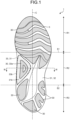
- FIG. 1 is a bottom view of a shoe 1 according to a first embodiment of the present invention.
- FIG. 1 only the shoe 1 for a left foot is illustrated. Since the shoe 1 has a left-right symmetrical structure for a left foot and a right foot, only the shoe 1 for a left foot is described in the present embodiment, and the description of the shoe 1 for a right foot is omitted.
- a direction in which a shoe center axis C, which is a perpendicular line passing through the center of shoe 1 in a bottom view of the shoe 1, extends is referred to as a front-rear direction
- a direction orthogonal to the front-rear direction in the bottom view of the shoe 1 is referred to as a foot width direction.
- a direction from the heel toward the toe of the shoe 1 in the front-rear direction is referred to as a front
- a direction from the toe toward the heel of the shoe 1 in the front-rear direction is referred to as a rear.
- a median side of a foot in the anatomical position is referred to as a medial foot side
- the side opposite to the median side of the foot in the anatomical position is referred to as a lateral foot side. That is, the side closer to the median line in the anatomical position is referred to as the medial foot side, and the side farther from the median line in the anatomical position is referred to as the lateral foot side.
- a vertical direction means a direction orthogonal to both the front-rear direction and the foot width direction unless otherwise specified.
- a sole 3 includes a forefoot support portion R1 that supports the forefoot of a foot of a wearer with a standard body shape, a midfoot support portion R2 that supports the midfoot of a foot of a wearer with a standard body shape, and a rearfoot support portion R3 that supports the rearfoot of a foot of a wearer with a standard body shape.
- the forefoot support portion R1, the midfoot support portion R2, and the rearfoot support portion R3 are connected in order from the front side toward the rear side of the sole 3.
- a line along the foot width direction passing through a position corresponding to about 37% of the dimension of the sole 3 from the front end of the sole 3 in the front-rear direction is defined as a first boundary line S1
- a line along the foot width direction passing through a position corresponding to about 71% of the dimension of the sole 3 from the front end of the sole 3 in the front-rear direction is defined as a second boundary line S2.
- the first boundary line S1 is a line roughly along the MP joint of a wearer with a standard body shape.
- the second boundary line S2 is a line roughly along the Chopart joint of a wearer with a standard body shape.
- the forefoot support portion R1 is positioned in front of the first boundary line S1.
- the midfoot support portion R2 is positioned between the first boundary line S1 and the second boundary line S2.
- the rearfoot support portion R3 is positioned behind the second boundary line S2.
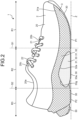
- FIG. 2 is a medial-foot-side side view of the shoe 1 according to the first embodiment of the present invention.
- the shoe 1 is preferably a running shoe but may be a shoe for other sports, a walking shoe, a climbing shoe, or the like.
- the shoe 1 includes an upper 2 and the sole 3.
- the upper 2 is positioned above the sole 3.
- the upper 2 includes an upper body 20, a shoe tongue 21, and a shoelace 22.
- the upper body 20 covers an instep side part of a foot of a wearer.
- the upper body 20 is formed with a foot insertion opening 20a and a throat portion 20b at its upper portion.
- the foot insertion opening 20a is an opening for inserting the foot of the wearer into the upper body 20.
- the throat portion 20b is an opening communicating with the foot insertion opening 20a and extending to the front side from the foot insertion opening 20a.
- a plurality of string passing portions 20c spaced apart from each other in the front-rear direction is provided on both side edges of the throat portion 20b in the foot width direction.
- FIG. 2 illustrates only the string passing portions 20c provided on the medial-foot-side side edge of the throat portion 20b.
- the string passing portions 20c are only required to allow the shoelace 22 to pass through.
- the string passing portions 20c are, for example, through holes that pass through the upper body 20 in the vertical direction.
- the shoe tongue 21 is a member for protecting the instep of the wearer.
- the shoe tongue 21 covers the throat portion 20b inside the upper body 20.
- the shoe tongue 21 is fixed to the upper body 20 by stitching, welding, bonding, or a combination thereof.
- the material of the upper body 20 and the shoe tongue 21 is, for example, woven fabric, knitted fabric, synthetic leather, or resin.
- the material of the upper body 20 and the shoe tongue 21 is preferably a double raschel warp knitted fabric knitted with polyester yarn. Note that the material of the upper body 20 and the shoe tongue 21 is not limited to those exemplified.
- the shoelace 22 is a string-like member that is alternately passed through the string passing portions 20c provided at one side edge of the throat portion 20b in the foot width direction and the string passing portions 20c provided at the other side edge in the foot width direction.
- the shoelace 22 is detachably attached to the upper body 20.
- the upper 2 including the shoe tongue 21 and the shoelace 22 is described as an example, but the upper 2 may have a monosock structure in which a portion corresponding to the shoe tongue 21 is integrated with an ankle portion of the upper body 20.
- a hook-and-loop fastener may be used instead of the shoelace 22 to bring the upper body 20 into close contact with the foot. If a hook-and-loop fastener is used to bring the upper body 20 into close contact with the foot, the string passing portions 20c are not formed in the upper body 20.
- the sole 3 is positioned below the upper 2.
- the sole 3 covers the sole of the wearer.
- the sole 3 is fixed to the upper 2 by stitching, welding, bonding, or a combination thereof.
- the sole 3 includes an outsole 30 and a midsole 31.
- the sole 3 includes an inner sole (not illustrated) that covers the lower opening of the upper body 20.
- the inner sole is fixed to the upper surface of the midsole 31 by bonding or welding.
- the inner sole is fixed to the lower edge of the upper body 20 by stitching.
- the shoe 1 may include an insole. If the shoe 1 includes an insole, the insole is installed on the sole 3 inside the upper 2.
- the sole 3 may have a structure in which the inner sole is omitted.
- the midsole 31 is positioned on the upper surface of the outsole 30.
- the midsole 31 is positioned between the upper 2 and the outsole 30.
- the midsole 31 is a soft member having a smaller Young's modulus than the outsole 30.
- the midsole 31 has a cushioning property.
- the midsole 31 is disposed over the entire region of the forefoot support portion R1, the midfoot support portion R2, and the rearfoot support portion R3.
- the midsole 31 has a first midsole portion 32 and a second midsole portion 33. Note that, in FIG. 2 , the first midsole portion 32 is diamondhatched, and the second midsole portion 33 is dot-hatched in order to facilitate understanding.
- the second midsole portion 33 is formed separately from the first midsole portion 32.
- the second midsole portion 33 is fixed to the first midsole portion 32 by welding, adhesion, or a combination thereof.
- the hardness of the second midsole portion 33 is lower than the hardness of the first midsole portion 32.
- the first midsole portion 32 is disposed over the entire region of the forefoot support portion R1, the midfoot support portion R2, and the rearfoot support portion R3.
- the second midsole portion 33 is disposed below a portion of the first midsole portion 32 positioned in the midfoot support portion R2.
- a cutout 32a recessed upward is formed in a lower surface of the portion of the first midsole portion 32 positioned in the midfoot support portion R2, and the second midsole portion 33 is disposed in the cutout 32a.
- the cutout 32a opens downward and toward the medial foot side.
- the side view shape of an upper surface 33g of the second midsole portion 33 is a curved shape protruding upward.
- the side view shape of the upper surface 33g of the second midsole portion 33 is a shape along the medial longitudinal arch of the foot or a shape approximating the medial longitudinal arch of the foot.
- the outer shape of the second midsole portion 33 is indicated by a broken line, the second midsole portion 33 is dot-hatched, and the outsole 30 is diagonal-hatched in order to facilitate understanding.
- the second midsole portion 33 is disposed only in a medial-foot-side region of the midfoot support portion R2 in the present embodiment.
- the second midsole portion 33 is only required to be disposed at least in a medial-foot-side region of the midfoot support portion R2.
- the second midsole portion 33 is only required to be disposed below at least a part or all of the medial longitudinal arch of the foot.
- the bottom surface of the second midsole portion 33 is a medial-foot-side region of the bottom surface of the midfoot support portion R2.
- the second midsole portion 33 is deformed by receiving the load when the shoe 1 comes contact with the ground to absorb an impact when the shoe 1 comes into contact with the ground.
- the bottom view shape of the second midsole portion 33 is a triangular shape in which the width in the front-rear direction narrows from the medial foot side toward the lateral foot side in the present embodiment.
- the second midsole portion 33 includes a ground contact portion 33a that comes into contact with the ground.
- the ground contact portion 33a is formed on the bottom surface of the second midsole portion 33.
- the ground contact portion 33a is the outsole 30 attached to the bottom surface of the second midsole portion 33 in the present embodiment.
- the ground contact portion 33a is positioned below the medial longitudinal arch of the foot.
- the position of the ground contact portion 33a in the front-rear direction is preferably within a region of 30% to 60% of the dimension of the sole 3 in the front-rear direction from the rear end of the sole 3.
- the position of the ground contact portion 33a in the foot width direction is preferably positioned on the medial foot side relative to the shoe center axis C. As illustrated in FIG.
- the ground contact portion 33a has a portion positioned on a lowermost line Z along the front-rear direction connecting a lowermost point P1 of the forefoot support portion R1 and a lowermost point P2 of the rearfoot support portion R3 in a side view.
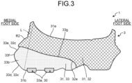
- FIG. 3 is a cross-sectional view taken along line III-III in FIG. 1 .
- the medial-foot-side side surface of the second midsole portion 33 is the medial-foot-side side surface of the midfoot support portion R2.
- the medial-foot-side side surface of the second midsole portion 33 is formed with a protrusion 33b protruding toward the medial foot side.
- the protrusion 33b is formed over the entire length of the medial-foot-side side surface of the second midsole portion 33.
- the protrusion 33b is preferably in a region ranging from 30% to 60% of the dimension of the sole 3 in the front-rear direction from the rear end of the sole 3.
- the protrusion 33b includes a protruding end surface 33c facing the medial foot side.
- the protruding end surface 33c has a first protruding end surface 33d and a second protruding end surface 33e.
- the first protruding end surface 33d extends upward from the medial-foot-side edge of a bottom surface 31b of the midsole 31 (the bottom surface of the second midsole portion 33) so as to be positioned toward the medial foot side.
- the second protruding end surface 33e is continuous with the first protruding end surface 33d and extends upward so as to be positioned toward the lateral foot side.
- the boundary between the first protruding end surface 33d and the second protruding end surface 33e is a vertex 33f of the protrusion 33b positioned on the medialmost foot side.
- the vertex 33f is a point of the protruding end surface 33c where the inclination direction is switched.
- the vertex 33f extends in the front-rear direction.
- the vertex 33f of the protrusion 33b is preferably positioned on the medial foot side relative to the virtual straight line L and below the center of the virtual straight line L in the vertical direction.
- the upper surface 33g of the second midsole portion 33 is inclined downward from the medial foot side toward the lateral foot side.
- the cross-sectional shape of the upper surface 33g of the second midsole portion 33 along the foot width direction is an inclined shape inclined downward from the medial foot side toward the lateral foot side.
- the outsole 30 is disposed below the midsole 31.
- the outsole 30 is a hard member having a larger Young's modulus than the midsole 31.
- the material of the outsole 30 is, for example, a material containing rubber as a main component and secondary components. Examples of the secondary components include a plasticizer, a reinforcing agent, and a crosslinking agent.
- the outsole 30 is partially disposed in the forefoot support portion R1, the midfoot support portion R2, and the rearfoot support portion R3.
- the outsole 30 is partially attached to the bottom surface 31b of the midsole 31.
- a part of the outsole 30 disposed in the midfoot support portion R2 serves as the ground contact portion 33a.
- the outsole 30 serving as the ground contact portion 33a and the other outsole 30 are provided independently of each other. In other words, the outsole 30 serving as the ground contact portion 33a and the other outsole 30 are separated from each other.
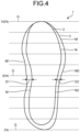
- FIG. 4 is a bottom view schematically illustrating a sole outline M and a fixed line N of the shoe 1 according to the first embodiment of the present invention.
- scale lines G are indicated in order to facilitate understanding.
- the scale line G at the position corresponding to the rear end of the sole 3 is defined as 0%, and the scale line G at the position corresponding to the front end of the sole 3 is defined as 100%.
- the scale line G is provided for each 10% of the dimension of the sole 3 in the front-rear direction.
- a line connecting the outermost portion of the sole 3 is defined as a sole outline M, and a line connecting the portion where the sole 3 and the upper 2 positioned above the sole 3 are fixed is defined as a fixed line N
- the sole outline M extends so as to surround the periphery of the fixed line N.
- the distance D1 and the distance D2 at the same position of the sole 3 in the front-rear direction satisfy a relationship of D1 > D2 in a region ranging from 30% to 60% of the dimension of the sole 3 in the front-rear direction from the rear end of the sole 3.
- the distance D1 and the distance D2 more preferably satisfy the relationship D1 > D2 in a region ranging from 20% to 80% of the dimension of the sole 3 in the front-rear direction from the rear end of the sole 3.
- the inventors of the present invention conducted experiments focusing on the angle of falling of the foot, a body posture, and the like in a fatigued state after a person run a predetermined distance. Specifically, the inventors had the subjects run a distance of 20 km or more, and observed and compared the inclination angle of the body, the state of the foot in contact with the ground, and the like at the initial stage of running when they were not fatigued and at the time when they were fatigued after running nearly 20 km.
- the inventors found that as the fatigue level of the subjects increases, the midfoot of the foot tends to come into contact with the ground at the same time when the heel of the foot comes into contact with the ground, which causes the medial longitudinal arch to easily collapse and that the pressure on the midfoot of the foot to the forefoot becomes higher than the pressure on the heel of the foot when the inward falling of the foot is the largest between the ground contact and the foot off. Therefore, if it is possible to control the inward falling of the foot even in a fatigued state due to running, the effect of maintaining the stability of the foot of a runner at the time of ground contact during the running period is expected for a long time.
- the ground contact portion 33a having a portion positioned on the lowermost line Z connecting the lowermost point P1 of the forefoot support portion R1 and the lowermost point P2 of the rearfoot support portion R3 in a side view is formed in the medial-foot-side region of the bottom surface of the midfoot support portion R2. Since the medial longitudinal arch of the foot is supported from below by the ground contact portion 33a, it is possible to control the collapse of the medial longitudinal arch of the foot.
- the medial-foot-side side surface of the midfoot support portion R2 is formed with the protrusion 33b protruding toward the medial foot side.
- the medial longitudinal arch of the foot is supported from the medial foot side by the protrusion 33b, it is possible to control the falling of the foot toward the medial foot side. That is, according to the present embodiment, it is possible to control the collapse of the medial longitudinal arch and the falling of the foot toward the medial foot side to stably support the midfoot of the sole of the wearer.
- To control the collapse of the medial longitudinal arch and the falling of the foot toward the medial foot side as in the present embodiment is particularly effective when a runner is increasingly fatigued. That is, it is possible to control overpronation under increased fatigue due to running.
- the protrusion 33b is formed on the medial-foot-side side surface of the midsole 31, and when a straight line connecting the medial-foot-side edge of the upper surface 31a of the midsole 31 and the medial-foot-side edge of the bottom surface 31b of the midsole 31 is defined as the virtual straight line L, the vertex 33f of the protrusion 33b is positioned on the medial foot side relative to the virtual straight line L and below the center of the virtual straight line L in the vertical direction.
- the protrusion 33b from locally bending when the medial longitudinal arch of the foot is about to fall toward the medial foot side. That is, when the medial longitudinal arch of the foot is about to fall toward the medial foot side, the compressive deformation of the protrusion 33b can be promoted. Therefore, it is possible to further control the falling of the foot toward the medial foot side.
- the protrusion 33b includes the protruding end surface 33c facing the medial foot side, and the protruding end surface 33c has the first protruding end surface 33d extending upward from the medial-foot-side edge of the bottom surface 31b of midsole 31 so as to be positioned toward the medial foot side, and the second protruding end surface 33e continuous with the first protruding end surface 33d and extending upward so as to be positioned toward the lateral foot side.
- the vertex 33f positioned at the boundary between the first protruding end surface 33d and the second protruding end surface 33e is positioned at a position separated upward from the ground, and it is possible to prevent the protrusion 33b from locally bending when the medial longitudinal arch of the foot is about to fall toward the medial foot side. That is, when the medial longitudinal arch of the foot is about to fall toward the medial foot side, the compressive deformation of the protrusion 33b can be promoted. Therefore, it is possible to further control the falling of the foot toward the medial foot side.
- the distance D1 in the foot width direction between the medial-foot-side portion M1 of the sole outline M and the medial-foot-side portion N1 of the fixed line N is longer than the distance D2 in the foot width direction between the lateral-foot-side portion M2 of the sole outline M and the lateral-foot-side portion N2 of the fixed line N.
- the outsole 30 serving as the ground contact portion 33a and the other outsole 30 are provided independently of each other.
- the load generated when the ground contact portion 33a comes into contact with the ground can be easily transmitted only to the second midsole portion 33 formed with the ground contact portion 33a, and it is possible to more reliably compress and deform the second midsole portion 33. Therefore, it is possible to enhance the cushioning property of the second midsole portion 33 of the sole 3 positioned below the medial longitudinal arch of the foot. In other words, it is possible for the second midsole portion 33 of the sole 3 positioned below the medial longitudinal arch of the foot to easily absorb an impact when the ground contact portion 33a comes into contact with the ground.
- the second midsole portion 33 positioned below the medial longitudinal arch where the wearer is likely to feel a thrust is formed separately from the first midsole portion 32, and the hardness of the second midsole portion 33 is lower than the hardness of the first midsole portion 32.
- the upper surface 33g of the second midsole portion 33 is inclined downward from the medial foot side toward the lateral foot side.
- the structure of the protrusion 33b is not limited to the illustrated example.
- the vertex 33f of the protrusion 33b is preferably positioned below the center of the virtual straight line L in the vertical direction, but may be positioned at the same height as the center of the virtual straight line L in the vertical direction or above the center of the virtual straight line L in the vertical direction.
- the shape of the protruding end surface 33c of the protrusion 33b is preferably the illustrated shape, but may be a linear shape along the vertical direction or may be a shape inclined from the upper side toward the lower side so as to be positioned toward the medial foot side.
- the ground contact portion 33a disposed in the midfoot support portion R2 is the outsole 30, but the ground contact portion 33a may be a part of the midsole 31.
- a part or all of the bottom surface of the second midsole portion 33 may be served as the ground contact portion 33a.
- the outsole 30 is only required to be disposed at least in the forefoot support portion R1 and the rearfoot support portion R3.
- the bottom view shape of the second midsole portion 33 illustrated in FIG. 1 , the side view shape of the upper surface 33g of the second midsole portion 33 illustrated in FIG. 2 , and the cross-sectional shape of the upper surface 33g of the second midsole portion 33 along the foot width direction illustrated in FIG. 3 are not limited to the illustrated examples, and may be appropriately changed.
- the cross-sectional shape of the upper surface 33g of the second midsole portion 33 along the foot width direction may be a flat shape along the foot width direction.
- FIG. 5 is a perspective view of a shoe 1A according to a second embodiment of the present invention.
- a shoe 1A according to the second embodiment is different from the shoe 1 according to the first embodiment in the range of a second midsole portion 33.
- the range of the second midsole portion 33 is indicated by a broken line.
- the second midsole portion 33 is disposed from a medial-foot-side region of a midfoot support portion R2 to a lateral-foot-side region of a rearfoot support portion R3.
- the second midsole portion 33 includes a first portion 33h, a second portion 33i, and a third portion 33j.
- the first portion 33h is disposed in the medial-foot-side region of the midfoot support portion R2.
- the third portion 33j extends obliquely rearward from the first portion 33h toward the lateral foot side.
- the third portion 33j is disposed over a part of a central region of the midfoot support portion R2 in the foot width direction and a part of a central region of the rearfoot support portion R3 in the foot width direction.
- the second portion 33i extends from the third portion 33j rearward and toward the lateral foot side.
- the second portion 33i is disposed over a part of a lateral-foot-side region of the midfoot support portion R2, the lateral-foot-side region of the rearfoot support portion R3, and a heel-side region of the rearfoot support portion R3.
- the second portion 33i reaches the rear end of the rearfoot support portion R3.
- the second midsole portion 33 is disposed avoiding a medial-foot-side region of the rearfoot support portion R3.
- a ground contact portion 33a is disposed on the bottom surface of the first portion 33h and the bottom surface of the second portion 33i.
- the ground contact portion 33a is disposed in the medial-foot-side region of the midfoot support portion R2 of the bottom surface of the second midsole portion 33 and in the lateral-foot-side region and the heel-side region of the rearfoot support portion R3 of the bottom surface of the second midsole portion 33.
- the third portion 33j may be omitted.
- the second midsole portion 33 is only required to be disposed in the medial-foot-side region of the midfoot support portion R2 and the lateral-foot-side region of the rearfoot support portion R3. In the present embodiment, it is possible to achieve the same effects as those of the first embodiment described above.
- the lateral-foot-side region of the rearfoot support portion R3 first comes into contact with the ground, and the lateral-foot-side region of the rearfoot support portion R3 toward the medial-foot-side region of the midfoot support portion R2 sequentially comes into contact with the ground.
- the second midsole portion 33 is disposed from the medial-foot-side region of the midfoot support portion R2 to the lateral-foot-side region of the rearfoot support portion R3.
- the second midsole portion 33 is disposed in the central region of the midfoot support portion R2 in the foot width direction and in the central region of the rearfoot support portion R3 in the foot width direction.
- FIG. 6 is a cross-sectional view illustrating a shoe 1B according to a third embodiment of the present invention and corresponds to a cross-sectional view taken along line III-III in FIG. 1 .
- the shoe 1B according to the third embodiment is different from the shoe 1 according to the first embodiment in that a plate 4 is disposed between a first midsole portion 32 and a second midsole portion 33.
- the plate 4 is disposed between the first midsole portion 32 and the second midsole portion 33.
- the plate 4 is disposed in a groove 34 formed in the bottom surface of the first midsole portion 32.
- the groove 34 is only required to be formed in one of the first midsole portion 32 and the second midsole portion 33.
- the hardness of the plate 4 is higher than the hardness of the first midsole portion 32 and the hardness of the second midsole portion 33.
- the material of the plate 4 is, for example, short carbon fiber reinforced material, fiber reinforced resin, non-fiber reinforced resin, or fiber fabric material.
- the fiber reinforced resin is, for example, carbon fiber, glass fiber, aramid fiber, Dyneema fiber, Zylon fiber, or boron fiber.
- the non-fiber reinforced resin is, for example, polymer resin.
- the polymer resin is, for example, thermoplastic polyurethane (TPU) or thermoplastic elastomer (TPA).
- TPU thermoplastic polyurethane
- TPA thermoplastic elastomer
- the fiber fabric material is, for example, knitted fabric or woven fabric of polyester fiber, nylon fiber, or the like. In the present embodiment, it is possible to achieve the same effects as those of the first embodiment described above.
- the plate 4 is disposed between the first midsole portion 32 and the second midsole portion 33, and the hardness of the plate 4 is higher than the hardness of the first midsole portion 32 and the hardness of the second midsole portion 33.
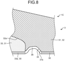
- FIG. 7 is a bottom view of a shoe 1C according to a fourth embodiment of the present invention.
- FIG. 8 is a cross-sectional view taken along line VIII-VIII in FIG. 7 .
- the shoe 1C according to the fourth embodiment is different from those according to the first to third embodiments in that at least a part of an outsole 30 serving as a ground contact portion 33a and at least a part of the other outsole 30 are connected to each other and that a portion where the outsole 30 serving as the ground contact portion 33a and the other outsole 30 are connected to each other is disposed in a recess 35.
- the portion where the outsole 30 serving as the ground contact portion 33a and the other outsole 30 are connected to each other can also be referred to as a connecting portion 36.
- the connecting portion 36 is also the outsole 30, the connecting portion 36 is not hatched in FIGS. 7 and 8 in order to clarify the range of the connecting portion 36.
- a bottom surface 31b of a midsole 31 is formed with the recess 35 recessed upward.
- the recess 35 is formed on the bottom surface of a first midsole portion 32 in the present embodiment.
- the recess 35 is disposed in a region in the periphery of the second midsole portion 33, excluding a region along the medial-foot-side edge.
- the connecting portion 36 is disposed in the recess 35.
- a boundary between the outsole 30 serving as the ground contact portion 33a and the connecting portion 36, and a boundary between the other outsole 30 and the connecting portion 36 are indicated by broken lines. At least a part of the outsole 30 serving as the ground contact portion 33a and at least a part of the other outsole 30 are only required to be connected to each other. In the present embodiment, it is possible to achieve the same effects as those of the first embodiment described above.
- the portion where the outsole 30 serving as the ground contact portion 33a and the other outsole 30 are connected to each other is disposed in the recess 35.
- a sole of a shoe according to the present invention has an effect of controlling overpronation under increased fatigue due to running.
Landscapes
- Health & Medical Sciences (AREA)
- Epidemiology (AREA)
- General Health & Medical Sciences (AREA)
- Public Health (AREA)
- Chemical & Material Sciences (AREA)
- Engineering & Computer Science (AREA)
- Materials Engineering (AREA)
- Footwear And Its Accessory, Manufacturing Method And Apparatuses (AREA)
Claims (10)
- Sohle (3) eines Schuhs (1), die aufweist: einen Vorderfußstützabschnitt (R1), der einen Vorderfuß eines Fußes eines Trägers stützt; einen Mittelfußstützabschnitt (R2), der einen Mittelfuß des Fußes des Trägers stützt; und einen Hinterfußstützabschnitt (R3), der einen Hinterfuß des Fußes des Trägers stützt, wobei der Vorderfußstützabschnitt, der Mittelfußstützabschnitt und der Hinterfußstützabschnitt der Reihe nach von einer Vorderseite in Richtung einer Hinterseite verbunden sind, wobeiein Bodenberührabschnitt (33a) der einen Abschnitt hat, der an einer untersten Linie positioniert ist, die einen untersten Punkt des Vorderfußstützabschnitts und einen untersten Punkt des Hinterfußstützabschnitts in einer Seitenansicht verbindet, in einem medialfußseitigen Bereich einer unteren Fläche des Mittelfußstützabschnitts ausgebildet ist, undein Vorsprung (33b), der in Richtung einer Medialfußseite vorsteht, an einer medialfußseitigen Seitenfläche des Mittelfußstützabschnitts ausgebildet ist, wobeiwenn eine Linie, die einen äußersten Abschnitt der Sohle verbindet, als eine Sohlenkontur definiert ist und eine Linie, die einen Abschnitt, bei dem die Sohle und ein Obermaterial (2), das über der Sohle positioniert ist, fixiert sind, als eine fixierte Linie definiert ist, in einer Unteransicht der Sohle, erstreckt sich die Sohlenkontur so, dass sie einen Umfang der fixierten Linie umgibt, dadurch gekennzeichnet, dassin einen Bereich, der von 30 % bis 60 % einer Abmessung der Sohle in einer Vorne-Hinten-Richtung von einem Hinterende der Sohle reicht, bei derselben Position der Sohle (3) in der Vorne-Hinten-Richtung eine Entfernung in einer Fußbreitenrichtung zwischen einem medialfußseitigen Abschnitt der Sohlenkontur und einem medialfußseitigen Abschnitt der fixierten Linie länger ist als eine Entfernung in der Fußbreitenrichtung zwischen einem lateralfußseitigen Abschnitt der Sohlenkontur und einem lateralfußseitigen Abschnitt der fixierten Linie.
- Sohle des Schuhs gemäß Anspruch 1, die ferner aufweist:eine Mittelsohle (31), die über den Vorderfußstützabschnitt, den Mittelfußstützabschnitt und den Hinterfußstützabschnitt hinweg angeordnet ist, wobeider Vorsprung an einer medialfußseitigen Seitenfläche der Mittelsohle ausgebildet ist, undwenn eine gerade Linie, die eine medialfußseitige Kante einer oberen Fläche der Mittelsohle und eine medialfußseitige Kante einer unteren Fläche der Mittelsohle verbindet, als eine virtuelle gerade Linie an einem Querschnitt in einer Breitenrichtung definiert ist, ein Scheitel (33f) des Vorsprungs an der Medialfußseite bezüglich der virtuellen geraden Linie und unter einem Zentrum der virtuellen geraden Linie in einer Vertikalrichtung positioniert ist.
- Sohle des Schuhs gemäß Anspruch 2, wobeider Vorsprung eine vorstehende Endfläche (33c) umfasst, die der Medialfußseite zugewandt ist, unddie vorstehende Endfläche eine erste vorstehende Endfläche (33d), die sich von der medialfußseitigen Kante der unteren Fläche der Mittelsohle in Richtung der Medialfußseite aufwärts erstreckt, und eine zweite vorstehende Endfläche (33e) hat, die mit der ersten vorstehenden Endfläche zusammenhängend ist und sich in Richtung einer Lateralfußseite aufwärts erstreckt.
- Sohle des Schuhs gemäß Anspruch 2, die ferner aufweist:eine Außensohle (30), die zumindest in dem Vorderfußstützabschnitt und dem Hinterfußstützabschnitt angeordnet ist und unter der Mittelsohle angeordnet ist, wobeider Bodenberührabschnitt und die Außensohle unabhängig voneinander vorgesehen sind.
- Sohle des Schuhs gemäß Anspruch 2, die ferner aufweist:eine Außensohle, die zumindest in dem Vorderfußstützabschnitt und dem Hinterfußstützabschnitt und unter der Mittelsohle angeordnet ist, wobeidie untere Fläche der Mittelsohle mit einer Vertiefung (35) ausgebildet ist, die aufwärts vertieft ist,mindestens ein Teil des Bodenberührabschnitts und mindestens ein Teil der Außensohle miteinander verbunden sind, undein Abschnitt, bei dem der Bodenberührabschnitt und die Außensohle miteinander verbunden sind, in der Vertiefung angeordnet ist.
- Sohle des Schuhs gemäß Anspruch 2, wobeidie Mittelsohle einen ersten Mittelsohlenabschnitt (32), der über den Vorderfußstützabschnitt, den Mittelfußstützabschnitt und den Hinterfußstützabschnitt hinweg angeordnet ist, und einen zweiten Mittelsohlenabschnitt (33) hat, der zumindest in einem medialfußseitigen Bereich des Mittelfußstützabschnitts angeordnet ist, unter dem ersten Mittelsohlenabschnitt angeordnet ist und den Bodenberührabschnitt umfasst, undeine Härte des zweiten Mittelsohlenabschnitts niedriger ist als eine Härte des ersten Mittelsohlenabschnitts.
- Sohle des Schuhs gemäß Anspruch 6, wobei eine obere Fläche des zweiten Mittelsohlenabschnitts von der Medialfußseite in Richtung einer Lateralfußseite abwärts geneigt ist.
- Sohle des Schuhs gemäß Anspruch 6, wobei eine Platte (4), die eine Härte hat, die höher ist als eine Härte des ersten Mittelsohlenabschnitts und eine Härte des zweiten Mittelsohlenabschnitts, zwischen dem ersten Mittelsohlenabschnitt und dem zweiten Mittelsohlenabschnitt angeordnet ist.
- Sohle des Schuhs gemäß Anspruch 6, wobeider zweite Mittelsohlenabschnitt von dem medialfußseitigen Bereich des Mittelfußstützabschnitts zu einem lateralfußseitigen Bereich des Hinterfußstützabschnitts angeordnet ist, undder Bodenberührabschnitt in dem medialfußseitigen Bereich des Mittelfußstützabschnitts der unteren Fläche des zweiten Mittelsohlenabschnitts und in dem lateralfußseitigen Bereich des Hinterfußstützabschnitts der unteren Fläche des zweiten Mittelsohlenabschnitts angeordnet ist.
- Schuh, der aufweist: Die Sohle des Schuhs gemäß einem der Ansprüche 1 bis 9; und ein Obermaterial, das über der Sohle des Schuhs positioniert ist.
Applications Claiming Priority (1)
| Application Number | Priority Date | Filing Date | Title |
|---|---|---|---|
| JP2022074392A JP2023163457A (ja) | 2022-04-28 | 2022-04-28 | 靴のソール及び靴 |
Publications (2)
| Publication Number | Publication Date |
|---|---|
| EP4268660A1 EP4268660A1 (de) | 2023-11-01 |
| EP4268660B1 true EP4268660B1 (de) | 2025-03-19 |
Family
ID=86272012
Family Applications (1)
| Application Number | Title | Priority Date | Filing Date |
|---|---|---|---|
| EP23170299.4A Active EP4268660B1 (de) | 2022-04-28 | 2023-04-27 | Sohle für schuh und schuh |
Country Status (4)
| Country | Link |
|---|---|
| US (1) | US12290146B2 (de) |
| EP (1) | EP4268660B1 (de) |
| JP (1) | JP2023163457A (de) |
| CN (1) | CN116965613A (de) |
Families Citing this family (10)
| Publication number | Priority date | Publication date | Assignee | Title |
|---|---|---|---|---|
| USD1000773S1 (en) * | 2022-06-24 | 2023-10-10 | Blakely Ventures, LLC | Shoe |
| USD982304S1 (en) | 2022-06-24 | 2023-04-04 | Blakely Ventures, LLC | Shoe last |
| USD1087569S1 (en) | 2022-10-14 | 2025-08-12 | Blakely Ventures, LLC | Shoe |
| USD1087570S1 (en) | 2022-10-14 | 2025-08-12 | Blakely Ventures, LLC | Shoe |
| USD1087568S1 (en) | 2022-10-14 | 2025-08-12 | Blakely Ventures, LLC | Shoe |
| USD1088451S1 (en) | 2022-10-14 | 2025-08-19 | Blakely Ventures, LLC | Shoe |
| USD1087551S1 (en) | 2022-10-14 | 2025-08-12 | Blakely Ventures, LLC | Shoe |
| USD1088432S1 (en) | 2022-10-14 | 2025-08-19 | Blakely Ventures, LLC | Shoe |
| USD1056428S1 (en) * | 2022-10-20 | 2025-01-07 | Asics Corporation | Shoe sole |
| USD1084624S1 (en) * | 2023-06-01 | 2025-07-22 | Caleres, Inc. | Shoe sole |
Citations (1)
| Publication number | Priority date | Publication date | Assignee | Title |
|---|---|---|---|---|
| EP4122348A1 (de) * | 2021-07-22 | 2023-01-25 | Deckers Outdoor Corporation | Schuhwerk mit stabilisierender sohle |
Family Cites Families (14)
| Publication number | Priority date | Publication date | Assignee | Title |
|---|---|---|---|---|
| US6662470B2 (en) * | 1989-08-30 | 2003-12-16 | Anatomic Research, Inc. | Shoes sole structures |
| US6163982A (en) * | 1989-08-30 | 2000-12-26 | Anatomic Research, Inc. | Shoe sole structures |
| US5915820A (en) * | 1996-08-20 | 1999-06-29 | Adidas A G | Shoe having an internal chassis |
| WO2000064293A1 (en) * | 1999-04-26 | 2000-11-02 | Anatomic Res Inc | Shoe sole orthotic structures and computer controlled compartments |
| US6915596B2 (en) * | 2003-01-21 | 2005-07-12 | Nike, Inc. | Footwear with separable upper and sole structure |
| JP3867054B2 (ja) * | 2003-02-10 | 2007-01-10 | 美津濃株式会社 | スポーツシューズのソール組立体 |
| JP4374235B2 (ja) * | 2003-10-31 | 2009-12-02 | 美津濃株式会社 | シューズのソール構造 |
| FR2899774B1 (fr) * | 2006-04-14 | 2008-08-29 | Salomon Sa | Systeme d'amortissement pour une chaussure |
| JP4153002B2 (ja) * | 2006-08-30 | 2008-09-17 | 美津濃株式会社 | シューズのソール組立体の中足部構造 |
| US8938889B2 (en) * | 2007-03-06 | 2015-01-27 | Deckers Outdoor Corporation | Footwear |
| US7946058B2 (en) * | 2007-03-21 | 2011-05-24 | Nike, Inc. | Article of footwear having a sole structure with an articulated midsole and outsole |
| US10178891B2 (en) | 2013-03-22 | 2019-01-15 | Reebok International Limited | Sole and article of footwear having a pod assembly |
| JP7550556B2 (ja) | 2020-07-14 | 2024-09-13 | 株式会社アシックス | 靴底および靴 |
| US12290136B2 (en) * | 2020-10-09 | 2025-05-06 | Asics Corporation | Sole and shoe including same |
-
2022
- 2022-04-28 JP JP2022074392A patent/JP2023163457A/ja active Pending
-
2023
- 2023-04-24 US US18/305,783 patent/US12290146B2/en active Active
- 2023-04-25 CN CN202310461613.4A patent/CN116965613A/zh active Pending
- 2023-04-27 EP EP23170299.4A patent/EP4268660B1/de active Active
Patent Citations (1)
| Publication number | Priority date | Publication date | Assignee | Title |
|---|---|---|---|---|
| EP4122348A1 (de) * | 2021-07-22 | 2023-01-25 | Deckers Outdoor Corporation | Schuhwerk mit stabilisierender sohle |
Also Published As
| Publication number | Publication date |
|---|---|
| EP4268660A1 (de) | 2023-11-01 |
| JP2023163457A (ja) | 2023-11-10 |
| US12290146B2 (en) | 2025-05-06 |
| US20230346070A1 (en) | 2023-11-02 |
| CN116965613A (zh) | 2023-10-31 |
Similar Documents
| Publication | Publication Date | Title |
|---|---|---|
| EP4268660B1 (de) | Sohle für schuh und schuh | |
| US11452335B2 (en) | Sole structure with plates and intervening fluid-filled bladder and method of manufacturing | |
| CN108378466B (zh) | 具有跟靠补足条带的鞋 | |
| US7263788B2 (en) | Sole-mounted footwear stability system | |
| US20220151337A1 (en) | Shoe sole and shoe | |
| JP7085649B2 (ja) | シューズ | |
| CA2260646A1 (en) | Article of footwear | |
| US12279670B2 (en) | Plate, sole, and shoe | |
| US12290136B2 (en) | Sole and shoe including same | |
| CN115426913B (zh) | 鞋底以及鞋 | |
| US20210282498A1 (en) | Shoes | |
| KR102854925B1 (ko) | 기능성 신발 | |
| EP4056067A1 (de) | Schuhsohle und schuh damit | |
| CN121337103A (zh) | 具有板和后跟支撑件的鞋类制品 |
Legal Events
| Date | Code | Title | Description |
|---|---|---|---|
| PUAI | Public reference made under article 153(3) epc to a published international application that has entered the european phase |
Free format text: ORIGINAL CODE: 0009012 |
|
| STAA | Information on the status of an ep patent application or granted ep patent |
Free format text: STATUS: REQUEST FOR EXAMINATION WAS MADE |
|
| 17P | Request for examination filed |
Effective date: 20230427 |
|
| AK | Designated contracting states |
Kind code of ref document: A1 Designated state(s): AL AT BE BG CH CY CZ DE DK EE ES FI FR GB GR HR HU IE IS IT LI LT LU LV MC ME MK MT NL NO PL PT RO RS SE SI SK SM TR |
|
| STAA | Information on the status of an ep patent application or granted ep patent |
Free format text: STATUS: EXAMINATION IS IN PROGRESS |
|
| 17Q | First examination report despatched |
Effective date: 20240508 |
|
| GRAP | Despatch of communication of intention to grant a patent |
Free format text: ORIGINAL CODE: EPIDOSNIGR1 |
|
| STAA | Information on the status of an ep patent application or granted ep patent |
Free format text: STATUS: GRANT OF PATENT IS INTENDED |
|
| INTG | Intention to grant announced |
Effective date: 20241008 |
|
| GRAS | Grant fee paid |
Free format text: ORIGINAL CODE: EPIDOSNIGR3 |
|
| GRAA | (expected) grant |
Free format text: ORIGINAL CODE: 0009210 |
|
| STAA | Information on the status of an ep patent application or granted ep patent |
Free format text: STATUS: THE PATENT HAS BEEN GRANTED |
|
| AK | Designated contracting states |
Kind code of ref document: B1 Designated state(s): AL AT BE BG CH CY CZ DE DK EE ES FI FR GB GR HR HU IE IS IT LI LT LU LV MC ME MK MT NL NO PL PT RO RS SE SI SK SM TR |
|
| REG | Reference to a national code |
Ref country code: GB Ref legal event code: FG4D |
|
| REG | Reference to a national code |
Ref country code: CH Ref legal event code: EP |
|
| REG | Reference to a national code |
Ref country code: IE Ref legal event code: FG4D |
|
| REG | Reference to a national code |
Ref country code: DE Ref legal event code: R096 Ref document number: 602023002440 Country of ref document: DE |
|
| PG25 | Lapsed in a contracting state [announced via postgrant information from national office to epo] |
Ref country code: RS Free format text: LAPSE BECAUSE OF FAILURE TO SUBMIT A TRANSLATION OF THE DESCRIPTION OR TO PAY THE FEE WITHIN THE PRESCRIBED TIME-LIMIT Effective date: 20250619 |
|
| PG25 | Lapsed in a contracting state [announced via postgrant information from national office to epo] |
Ref country code: FI Free format text: LAPSE BECAUSE OF FAILURE TO SUBMIT A TRANSLATION OF THE DESCRIPTION OR TO PAY THE FEE WITHIN THE PRESCRIBED TIME-LIMIT Effective date: 20250319 |
|
| PGFP | Annual fee paid to national office [announced via postgrant information from national office to epo] |
Ref country code: DE Payment date: 20250423 Year of fee payment: 3 |
|
| REG | Reference to a national code |
Ref country code: LT Ref legal event code: MG9D |
|
| PG25 | Lapsed in a contracting state [announced via postgrant information from national office to epo] |
Ref country code: NO Free format text: LAPSE BECAUSE OF FAILURE TO SUBMIT A TRANSLATION OF THE DESCRIPTION OR TO PAY THE FEE WITHIN THE PRESCRIBED TIME-LIMIT Effective date: 20250619 |
|
| PG25 | Lapsed in a contracting state [announced via postgrant information from national office to epo] |
Ref country code: HR Free format text: LAPSE BECAUSE OF FAILURE TO SUBMIT A TRANSLATION OF THE DESCRIPTION OR TO PAY THE FEE WITHIN THE PRESCRIBED TIME-LIMIT Effective date: 20250319 |
|
| PG25 | Lapsed in a contracting state [announced via postgrant information from national office to epo] |
Ref country code: LV Free format text: LAPSE BECAUSE OF FAILURE TO SUBMIT A TRANSLATION OF THE DESCRIPTION OR TO PAY THE FEE WITHIN THE PRESCRIBED TIME-LIMIT Effective date: 20250319 |
|
| PG25 | Lapsed in a contracting state [announced via postgrant information from national office to epo] |
Ref country code: GR Free format text: LAPSE BECAUSE OF FAILURE TO SUBMIT A TRANSLATION OF THE DESCRIPTION OR TO PAY THE FEE WITHIN THE PRESCRIBED TIME-LIMIT Effective date: 20250620 Ref country code: BG Free format text: LAPSE BECAUSE OF FAILURE TO SUBMIT A TRANSLATION OF THE DESCRIPTION OR TO PAY THE FEE WITHIN THE PRESCRIBED TIME-LIMIT Effective date: 20250319 |
|
| REG | Reference to a national code |
Ref country code: NL Ref legal event code: MP Effective date: 20250319 |
|
| REG | Reference to a national code |
Ref country code: AT Ref legal event code: MK05 Ref document number: 1776178 Country of ref document: AT Kind code of ref document: T Effective date: 20250319 |
|
| PG25 | Lapsed in a contracting state [announced via postgrant information from national office to epo] |
Ref country code: NL Free format text: LAPSE BECAUSE OF FAILURE TO SUBMIT A TRANSLATION OF THE DESCRIPTION OR TO PAY THE FEE WITHIN THE PRESCRIBED TIME-LIMIT Effective date: 20250319 |
|
| PG25 | Lapsed in a contracting state [announced via postgrant information from national office to epo] |
Ref country code: SE Free format text: LAPSE BECAUSE OF FAILURE TO SUBMIT A TRANSLATION OF THE DESCRIPTION OR TO PAY THE FEE WITHIN THE PRESCRIBED TIME-LIMIT Effective date: 20250319 |
|
| PG25 | Lapsed in a contracting state [announced via postgrant information from national office to epo] |
Ref country code: SM Free format text: LAPSE BECAUSE OF FAILURE TO SUBMIT A TRANSLATION OF THE DESCRIPTION OR TO PAY THE FEE WITHIN THE PRESCRIBED TIME-LIMIT Effective date: 20250319 |
|
| PG25 | Lapsed in a contracting state [announced via postgrant information from national office to epo] |
Ref country code: ES Free format text: LAPSE BECAUSE OF FAILURE TO SUBMIT A TRANSLATION OF THE DESCRIPTION OR TO PAY THE FEE WITHIN THE PRESCRIBED TIME-LIMIT Effective date: 20250319 Ref country code: PT Free format text: LAPSE BECAUSE OF FAILURE TO SUBMIT A TRANSLATION OF THE DESCRIPTION OR TO PAY THE FEE WITHIN THE PRESCRIBED TIME-LIMIT Effective date: 20250721 |
|
| PG25 | Lapsed in a contracting state [announced via postgrant information from national office to epo] |
Ref country code: PL Free format text: LAPSE BECAUSE OF FAILURE TO SUBMIT A TRANSLATION OF THE DESCRIPTION OR TO PAY THE FEE WITHIN THE PRESCRIBED TIME-LIMIT Effective date: 20250319 Ref country code: IT Free format text: LAPSE BECAUSE OF FAILURE TO SUBMIT A TRANSLATION OF THE DESCRIPTION OR TO PAY THE FEE WITHIN THE PRESCRIBED TIME-LIMIT Effective date: 20250319 |
|
| PG25 | Lapsed in a contracting state [announced via postgrant information from national office to epo] |
Ref country code: AT Free format text: LAPSE BECAUSE OF FAILURE TO SUBMIT A TRANSLATION OF THE DESCRIPTION OR TO PAY THE FEE WITHIN THE PRESCRIBED TIME-LIMIT Effective date: 20250319 |
|
| PG25 | Lapsed in a contracting state [announced via postgrant information from national office to epo] |
Ref country code: EE Free format text: LAPSE BECAUSE OF FAILURE TO SUBMIT A TRANSLATION OF THE DESCRIPTION OR TO PAY THE FEE WITHIN THE PRESCRIBED TIME-LIMIT Effective date: 20250319 Ref country code: CZ Free format text: LAPSE BECAUSE OF FAILURE TO SUBMIT A TRANSLATION OF THE DESCRIPTION OR TO PAY THE FEE WITHIN THE PRESCRIBED TIME-LIMIT Effective date: 20250319 |
|
| PG25 | Lapsed in a contracting state [announced via postgrant information from national office to epo] |
Ref country code: RO Free format text: LAPSE BECAUSE OF FAILURE TO SUBMIT A TRANSLATION OF THE DESCRIPTION OR TO PAY THE FEE WITHIN THE PRESCRIBED TIME-LIMIT Effective date: 20250319 |
|
| PG25 | Lapsed in a contracting state [announced via postgrant information from national office to epo] |
Ref country code: SK Free format text: LAPSE BECAUSE OF FAILURE TO SUBMIT A TRANSLATION OF THE DESCRIPTION OR TO PAY THE FEE WITHIN THE PRESCRIBED TIME-LIMIT Effective date: 20250319 |
|
| PG25 | Lapsed in a contracting state [announced via postgrant information from national office to epo] |
Ref country code: IS Free format text: LAPSE BECAUSE OF FAILURE TO SUBMIT A TRANSLATION OF THE DESCRIPTION OR TO PAY THE FEE WITHIN THE PRESCRIBED TIME-LIMIT Effective date: 20250719 |
|
| PG25 | Lapsed in a contracting state [announced via postgrant information from national office to epo] |
Ref country code: LU Free format text: LAPSE BECAUSE OF NON-PAYMENT OF DUE FEES Effective date: 20250427 |
|
| PG25 | Lapsed in a contracting state [announced via postgrant information from national office to epo] |
Ref country code: MC Free format text: LAPSE BECAUSE OF FAILURE TO SUBMIT A TRANSLATION OF THE DESCRIPTION OR TO PAY THE FEE WITHIN THE PRESCRIBED TIME-LIMIT Effective date: 20250319 |
|
| REG | Reference to a national code |
Ref country code: DE Ref legal event code: R097 Ref document number: 602023002440 Country of ref document: DE |
|
| REG | Reference to a national code |
Ref country code: BE Ref legal event code: MM Effective date: 20250430 |
|
| PG25 | Lapsed in a contracting state [announced via postgrant information from national office to epo] |
Ref country code: DK Free format text: LAPSE BECAUSE OF FAILURE TO SUBMIT A TRANSLATION OF THE DESCRIPTION OR TO PAY THE FEE WITHIN THE PRESCRIBED TIME-LIMIT Effective date: 20250319 |
|
| PG25 | Lapsed in a contracting state [announced via postgrant information from national office to epo] |
Ref country code: BE Free format text: LAPSE BECAUSE OF NON-PAYMENT OF DUE FEES Effective date: 20250430 |
|
| PLBE | No opposition filed within time limit |
Free format text: ORIGINAL CODE: 0009261 |
|
| STAA | Information on the status of an ep patent application or granted ep patent |
Free format text: STATUS: NO OPPOSITION FILED WITHIN TIME LIMIT |
|
| REG | Reference to a national code |
Ref country code: CH Ref legal event code: L10 Free format text: ST27 STATUS EVENT CODE: U-0-0-L10-L00 (AS PROVIDED BY THE NATIONAL OFFICE) Effective date: 20260128 |
|
| 26N | No opposition filed |
Effective date: 20251222 |
|
| PG25 | Lapsed in a contracting state [announced via postgrant information from national office to epo] |
Ref country code: IE Free format text: LAPSE BECAUSE OF NON-PAYMENT OF DUE FEES Effective date: 20250427 |
|
| PG25 | Lapsed in a contracting state [announced via postgrant information from national office to epo] |
Ref country code: FR Free format text: LAPSE BECAUSE OF NON-PAYMENT OF DUE FEES Effective date: 20250519 |