US12243720B2 - Gas supply block and substrate-processing apparatus including the same - Google Patents
Gas supply block and substrate-processing apparatus including the same Download PDFInfo
- Publication number
- US12243720B2 US12243720B2 US17/517,068 US202117517068A US12243720B2 US 12243720 B2 US12243720 B2 US 12243720B2 US 202117517068 A US202117517068 A US 202117517068A US 12243720 B2 US12243720 B2 US 12243720B2
- Authority
- US
- United States
- Prior art keywords
- block
- gas
- partition
- gas supply
- inserting groove
- Prior art date
- Legal status (The legal status is an assumption and is not a legal conclusion. Google has not performed a legal analysis and makes no representation as to the accuracy of the status listed.)
- Active, expires
Links
Images


Classifications
-
- C—CHEMISTRY; METALLURGY
- C23—COATING METALLIC MATERIAL; COATING MATERIAL WITH METALLIC MATERIAL; CHEMICAL SURFACE TREATMENT; DIFFUSION TREATMENT OF METALLIC MATERIAL; COATING BY VACUUM EVAPORATION, BY SPUTTERING, BY ION IMPLANTATION OR BY CHEMICAL VAPOUR DEPOSITION, IN GENERAL; INHIBITING CORROSION OF METALLIC MATERIAL OR INCRUSTATION IN GENERAL
- C23C—COATING METALLIC MATERIAL; COATING MATERIAL WITH METALLIC MATERIAL; SURFACE TREATMENT OF METALLIC MATERIAL BY DIFFUSION INTO THE SURFACE, BY CHEMICAL CONVERSION OR SUBSTITUTION; COATING BY VACUUM EVAPORATION, BY SPUTTERING, BY ION IMPLANTATION OR BY CHEMICAL VAPOUR DEPOSITION, IN GENERAL
- C23C16/00—Chemical coating by decomposition of gaseous compounds, without leaving reaction products of surface material in the coating, i.e. chemical vapour deposition [CVD] processes
- C23C16/44—Chemical coating by decomposition of gaseous compounds, without leaving reaction products of surface material in the coating, i.e. chemical vapour deposition [CVD] processes characterised by the method of coating
- C23C16/455—Chemical coating by decomposition of gaseous compounds, without leaving reaction products of surface material in the coating, i.e. chemical vapour deposition [CVD] processes characterised by the method of coating characterised by the method used for introducing gases into reaction chamber or for modifying gas flows in reaction chamber
-
- H—ELECTRICITY
- H01—ELECTRIC ELEMENTS
- H01J—ELECTRIC DISCHARGE TUBES OR DISCHARGE LAMPS
- H01J37/00—Discharge tubes with provision for introducing objects or material to be exposed to the discharge, e.g. for the purpose of examination or processing thereof
- H01J37/32—Gas-filled discharge tubes
- H01J37/32431—Constructional details of the reactor
- H01J37/3244—Gas supply means
- H01J37/32449—Gas control, e.g. control of the gas flow
-
- H—ELECTRICITY
- H01—ELECTRIC ELEMENTS
- H01J—ELECTRIC DISCHARGE TUBES OR DISCHARGE LAMPS
- H01J37/00—Discharge tubes with provision for introducing objects or material to be exposed to the discharge, e.g. for the purpose of examination or processing thereof
- H01J37/32—Gas-filled discharge tubes
- H01J37/32431—Constructional details of the reactor
- H01J37/32715—Workpiece holder
-
- H—ELECTRICITY
- H10—SEMICONDUCTOR DEVICES; ELECTRIC SOLID-STATE DEVICES NOT OTHERWISE PROVIDED FOR
- H10P—GENERIC PROCESSES OR APPARATUS FOR THE MANUFACTURE OR TREATMENT OF DEVICES COVERED BY CLASS H10
- H10P14/00—Formation of materials, e.g. in the shape of layers or pillars
- H10P14/60—Formation of materials, e.g. in the shape of layers or pillars of insulating materials
- H10P14/65—Formation of materials, e.g. in the shape of layers or pillars of insulating materials characterised by treatments performed before or after the formation of the materials
- H10P14/6502—Formation of materials, e.g. in the shape of layers or pillars of insulating materials characterised by treatments performed before or after the formation of the materials of treatments performed before formation of the materials
- H10P14/6512—Formation of materials, e.g. in the shape of layers or pillars of insulating materials characterised by treatments performed before or after the formation of the materials of treatments performed before formation of the materials by exposure to a gas or vapour
-
- H—ELECTRICITY
- H10—SEMICONDUCTOR DEVICES; ELECTRIC SOLID-STATE DEVICES NOT OTHERWISE PROVIDED FOR
- H10P—GENERIC PROCESSES OR APPARATUS FOR THE MANUFACTURE OR TREATMENT OF DEVICES COVERED BY CLASS H10
- H10P72/00—Handling or holding of wafers, substrates or devices during manufacture or treatment thereof
- H10P72/04—Apparatus for manufacture or treatment
- H10P72/0402—Apparatus for fluid treatment
-
- H—ELECTRICITY
- H10—SEMICONDUCTOR DEVICES; ELECTRIC SOLID-STATE DEVICES NOT OTHERWISE PROVIDED FOR
- H10P—GENERIC PROCESSES OR APPARATUS FOR THE MANUFACTURE OR TREATMENT OF DEVICES COVERED BY CLASS H10
- H10P72/00—Handling or holding of wafers, substrates or devices during manufacture or treatment thereof
- H10P72/04—Apparatus for manufacture or treatment
- H10P72/0431—Apparatus for thermal treatment
- H10P72/0432—Apparatus for thermal treatment mainly by conduction
-
- H—ELECTRICITY
- H10—SEMICONDUCTOR DEVICES; ELECTRIC SOLID-STATE DEVICES NOT OTHERWISE PROVIDED FOR
- H10P—GENERIC PROCESSES OR APPARATUS FOR THE MANUFACTURE OR TREATMENT OF DEVICES COVERED BY CLASS H10
- H10P72/00—Handling or holding of wafers, substrates or devices during manufacture or treatment thereof
- H10P72/70—Handling or holding of wafers, substrates or devices during manufacture or treatment thereof for supporting or gripping
- H10P72/76—Handling or holding of wafers, substrates or devices during manufacture or treatment thereof for supporting or gripping using mechanical means, e.g. clamps or pinches
- H10P72/7604—Handling or holding of wafers, substrates or devices during manufacture or treatment thereof for supporting or gripping using mechanical means, e.g. clamps or pinches the wafers being placed on a susceptor, stage or support
- H10P72/7612—Handling or holding of wafers, substrates or devices during manufacture or treatment thereof for supporting or gripping using mechanical means, e.g. clamps or pinches the wafers being placed on a susceptor, stage or support characterised by lifting arrangements, e.g. lift pins
-
- H—ELECTRICITY
- H10—SEMICONDUCTOR DEVICES; ELECTRIC SOLID-STATE DEVICES NOT OTHERWISE PROVIDED FOR
- H10P—GENERIC PROCESSES OR APPARATUS FOR THE MANUFACTURE OR TREATMENT OF DEVICES COVERED BY CLASS H10
- H10P72/00—Handling or holding of wafers, substrates or devices during manufacture or treatment thereof
- H10P72/70—Handling or holding of wafers, substrates or devices during manufacture or treatment thereof for supporting or gripping
- H10P72/76—Handling or holding of wafers, substrates or devices during manufacture or treatment thereof for supporting or gripping using mechanical means, e.g. clamps or pinches
- H10P72/7604—Handling or holding of wafers, substrates or devices during manufacture or treatment thereof for supporting or gripping using mechanical means, e.g. clamps or pinches the wafers being placed on a susceptor, stage or support
- H10P72/7618—Handling or holding of wafers, substrates or devices during manufacture or treatment thereof for supporting or gripping using mechanical means, e.g. clamps or pinches the wafers being placed on a susceptor, stage or support characterised by a movable susceptor, stage or support, others than those only rotating on their own vertical axis, e.g. susceptors on a rotating carrousel
Definitions
- Various embodiments may generally relate to a substrate-processing apparatus, more particularly, to a gas supply block and a substrate-processing apparatus including the gas supply block.
- the substrate-processing apparatus may include a process chamber having a plurality of processing spaces configured to process the substrates, a plurality of gas injectors arranged at an upper portion of the process chamber to inject a process gas into the processing spaces, and a plurality of substrate supports arranged in the process chamber corresponding to the gas injectors to support the substrates.
- the substrate-processing apparatus may include a gas supplying member configured to supply the process gas to the gas injectors, and a gas branching member configured to branch the process gas supplied from the gas supplying member into the gas injectors.
- the gas injector and the gas branching member may be connected with each other through one gas supply line. Further, each of the gas branching member and the gas injectors may be connected with each other through one gas branch line.
- the substrate-processing apparatus may be configured to form a composite layer
- different kinds of the process gases may be alternately supplied through one gas supply line.
- the gas supply line may not be fully purged to increase a generation of particles. This may cause bad line edge roughness.
- a first process gas for forming a first layer and a second process gas for forming a second layer may be alternately supplied through one gas supply line.
- a purge time for removing the process gas in the gas supply line before supplying the second process gas after supplying the first process gas and before supplying the first process gas after supplying the second process gas may be increased.
- a gas supply block may be configured to supply a process gas into a chamber having a plurality of processing spaces.
- the gas supply block may include a lower block and an upper block.
- the lower block may include a plurality of first gas supply passages and a first gas inlet passage.
- the first gas supply passages may be configured to supply a first process gas into each of the processing spaces.
- the first gas inlet passage may be configured to introduce the first process gas into the first gas supply passages.
- the upper block may be combined with the lower block.
- the upper block may include a plurality of second gas supply passages and a second gas inlet passage.
- the second gas supply passages may be configured to supply a second process gas different from the first process gas into the processing spaces.
- the second gas inlet passage may be configured to introduce the second process gas into the second gas supply passages.
- a substrate-processing apparatus may include a chamber, a plurality of substrate supports, a plurality of gas injectors and a gas supply block.
- the chamber may include a plurality of processing spaces.
- the substrate supports may be arranged in the processing spaces of the chamber.
- the gas injectors may be arranged in the processing spaces to correspond to the substrate supports.
- the gas supply block may be configured to alternately supply a first process gas and a second process gas different from the first process gas into the gas injectors.
- the gas supply block may include a lower block and an upper block.
- the lower block may include a plurality of first gas supply passages and a first gas inlet passage.
- the first gas supply passages may be configured to supply the first process gas into each of the processing spaces.
- the first gas inlet passage may be configured to introduce the first process gas into the first gas supply passages.
- the upper block may be combined with the lower block.
- the upper block may include a plurality of second gas supply passages and a second gas inlet passage.
- the second gas supply passages may be configured to supply the second process gas different from the first process gas into the processing spaces.
- the second gas inlet passage may be configured to introduce the second process gas into the second gas supply passages.
- a gas supply block may be configured to supply a process gas into a chamber having a plurality of processing spaces.
- the gas supply block may include a first block, a second block and a third block.
- the first block may include a first gas inlet passage configured to supply a first process gas.
- the second block may include a second gas inlet passage configured to supply a second process gas.
- the third block may be combined with the first block and the second block.
- the third block may be configured to diffuse and supply the first process gas and the second process gas into gas supply lines connected to the processing spaces.
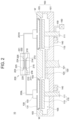
- FIG. 1 is a plan view illustrating a substrate-processing apparatus including a gas supply block in accordance with example embodiments
- FIG. 2 is a cross-sectional view taken along a line I-I′ in FIG. 1 ;
- FIG. 3 is a perspective view illustrating a gas supply block in accordance with example embodiments
- FIG. 4 is a cross-sectional view taken along a line II-II′ in FIG. 3 ;
- FIG. 5 is a view illustrating a direction of a gas flow in a gas supply block in accordance with example embodiments
- FIG. 6 is a perspective view illustrating a gas supply block in accordance with example embodiments.
- FIG. 7 is an exploded perspective view illustrating a gas supply block in accordance with example embodiments.
- FIG. 1 is a plan view illustrating a substrate-processing apparatus including a gas supply block in accordance with example embodiments and FIG. 2 is a cross-sectional view taken along a line I-I′ in FIG. 1 .
- a substrate-processing apparatus 10 of example embodiments may include a chamber 100 , a substrate support 110 , a gas injector 130 and a gas supply block 200 .
- the chamber 100 may have a processing space.
- the substrate support 110 may be arranged in the chamber 100 to support a substrate W.
- the gas injector 130 may be arranged facing the substrate support 110 to inject a process gas to the substrate support 110 .
- the gas supply block 200 may be arranged over the chamber 100 to supply the process gas to the gas injector 130 .
- the substrate-processing apparatus 10 may further include a substrate transfer 120 arranged outside the substrate support 110 to assist a transfer of the substrate W.
- the chamber 100 may include a body 101 having an opened upper surface and a top lid 103 installed at the upper surface of the body 101 to open and close the upper surface of the body 101 .
- a receiving groove 105 may be formed in the body 101 to receive the substrate support 110 .
- the receiving groove 105 may have a shape corresponding to a shape of a supporting plate 113 .
- the receiving groove 105 may have a circular shape.
- the receiving groove 105 may have a depth.
- the depth of the receiving groove 105 may correspond to movement ranges in upward and downward directions of the supporting plate 113 . This configuration may reduce a size of an inner space of the chamber 100 to decrease an amount of the process gas supplied to the chamber 100 and a time for purging the chamber 100 .
- a hole may be formed through the receiving groove 105 .
- a supporting shaft 111 of the substrate support 110 may be inserted into the hole. Further, as shown in FIG. 1 , when the chamber 100 may process the four substrates W, the four receiving grooves 105 may also be formed.
- the four receiving grooves 105 may be connected with each other through exhaust passages.
- the exhaust passages may be horizontally formed along a bottom surface of the body 101 .
- the exhaust passages may be connected to an exhaust port 140 vertically formed through the bottom surface of the body 101 .
- the exhaust passages may be connected with an exhaust line 150 connected to a vacuum pump 160 .
- a hole may be formed through the bottom surface of the body 101 .
- a rotation shaft 121 of the substrate transfer 120 may be inserted into the hole.
- the hole may be formed through a central portion of the bottom surface of the body 101 .
- a gate may be formed at a side surface of the body 101 .
- the substrate W may be loaded/unloaded into/from the chamber 100 through the gate.
- the top lid 103 may be combined with the body 101 to close the body 101 .
- the top lid 103 may have a size for covering the whole upper surface of the body 101 .
- the top lid 103 may be combined with the gas injector 130 to partially cover the upper surface of the body 101 .
- a hole may be vertically formed through the top lid 103 .
- the gas injector 130 may be inserted into the hole from an upper region of the top lid 103 , not limited thereto.
- the substrate support 110 may be configured to support the substrate W.
- the substrate support 110 may be arranged in a lower region of the chamber 100 .
- the substrate support 110 may include the supporting plate 113 and the supporting shaft 111 .
- the substrate W may be placed on the supporting plate 113 .
- the supporting shaft 111 may be connected to a lower surface of the supporting plate 113 to lift the supporting plate 113 .
- the supporting plate 113 may have a plate shape having a thickness.
- the supporting plate 113 may have a shape corresponding to a shape of the substrate W.
- the substrate W may include a circular wafer
- the supporting plate 113 may have a circular shape, not limited thereto.
- the supporting plate 113 may be substantially parallel to the bottom surface of the body 101 .
- the supporting shaft 111 may be substantially perpendicular to the bottom surface of the body 101 .
- the supporting shaft 111 may be connected with a driver such as a motor through a hole formed through the bottom surface of the body 101 to lift the supporting plate 113 .
- a bellows may be installed between the supporting shaft 111 and the hole to seal a space between the supporting shaft 111 and the hole, thereby maintain vacuum in the chamber 100 during processing the substrate W.
- a heater for heating the supporting plate 113 may be installed in the supporting plate 113 .
- the heater may be connected to a power source through a cable. When a power may be applied to the heater, the heater may heat the supporting plate 113 to heat the substrate W on the supporting plate 113 .
- the supporting plate 113 may function as a lower electrode as well as the support.
- an electric field may be generated between the supporting plate 113 and the gas injector 130 .
- an RF power and a ground power may be applied to the gas injector 130 and the supporting plate 113 , respectively, to generate the electric field between the gas injector 130 and the supporting plate 113 , thereby forming plasma in the chamber 100 .
- a ground electrode may be installed in the supporting plate 113 .
- a plurality of the substrate supports 110 may be arranged in the chamber 100 .
- the four substrate supports 110 may be placed in the chamber 100 .
- the substrate supports 110 may be arranged in a point symmetrical shape with respect to a center of the chamber 100 .
- the substrate support 110 may be one, two, three or no less than five.
- the substrate transfer 120 may move the substrate W between the substrate supports 110 .
- the substrate transfer 120 may include a rotation shaft 121 and a turn table 123 .
- the rotation shaft 121 may be inserted into a hole formed through the bottom surface of the body 101 .
- the turn table 123 may be horizontally installed at an upper end of the rotation shaft 121 .
- the rotation shaft 121 may be arranged at a center of the supporting shafts 111 in the substrate supports 110 .
- the rotation shaft 121 may be connected to an actuator such as a motor to rotate and lift the turn table 123 .
- a bellows may be installed between the rotation shaft 121 and the hole to seal a space between the rotation shaft 121 and the hole, thereby maintain the vacuum in the chamber 100 .
- the turn table 123 may have a plate shape having a thickness.
- the turn table 123 may be rotated together with the substrate W on the supporting plate 113 to change positions of the substrate W.
- the gas injector 130 may face the supporting plate 113 in the chamber 100 .
- the gas injector 130 may be spaced apart from the supporting plate 113 .
- the gas injector 130 may inject the process gas to the supporting plate 113 .
- the gas injector 130 may be connected to a power source to function as an upper electrode for generating the plasma. For example, an RF power may be applied to the gas injector 130 and the supporting plate 113 may be grounded to generate the plasma in the chamber 100 .
- the gas injector 130 may generate the plasma from the process gas.
- the gas injector 130 may then inject the plasma into the chamber 100 . Further, the plasma may be generated outside the chamber 100 .
- the plasma may then be supplied into the chamber 100 .
- the gas injector 130 may form the upper surface of the chamber 100 together with the top lid 103 .
- the gas injector 130 may be connected to a single gas source for supplying a same kind of the process gas or a plurality of gas sources for supplying different kinds of the process gases.
- the gas injector 130 may include a showerhead having a plurality of injection holes, not limited thereto.
- the gas injector 130 may include a plurality of injectors.
- the four gas injectors 130 may be installed at the top lid 103 .
- the gas injectors 130 may be arranged in a point symmetrical shape with respect to a center of the top lid 103 .
- numbers of the gas injector 130 may be no more than three or no less than five.
- the gas injector 130 may include a gas injection block 131 and a gas inlet block 133 .
- the gas inlet block 133 may be configured to connect the gas injection block 131 with gas supply lines 251 , 253 , 255 and 257 .
- the gas injection block 131 may have a first surface and a second surface. The first surface may be adjacent to the supporting plate 113 .
- the gas inlet block 133 may be installed at the second surface.
- a plurality of injection holes for injecting the process gas may be formed through the first surface of the gas injection block 131 .
- a hole may be formed through the second surface of the gas injection block 131 .
- the process gas supplied into the gas inlet block 133 may pass through the hole.
- the gas injection block 131 may have a shape in FIG. 2 , not limited thereto.
- the gas supply block 200 may be installed at the upper surface of the chamber 100 .
- the gas supply block 200 may be spaced apart from the top lid 103 .
- the gas supply block 200 may supply the process gas to the gas injector 130 through the gas supply lines 251 , 253 , 255 and 257 .
- the gas supply block 200 may include a lower block 210 and an upper block 220 .
- the lower block 210 and the upper block 220 may have substantially the same shape, not limited thereto.
- different kinds of the process gases may be supplied to the lower block 210 and the upper block 220 , respectively, not limited thereto.
- An inlet hole may be formed through a bottom surface of the annular partition 224 of the third block 221 .
- the process gas may pass through the inlet hole.
- the inlet hole may be connected to the second gas inlet passage 227 .
- the second gas inlet passage 227 may be connected to a gas supply pipe 300 H in FIG. 5 connected with a gas source.
- the second block 2200 may be positioned over the first block 2100 .
- the second block 2200 may have a shape formed by rotating the first block 2100 at an angle of about 180°.
- the second block 2200 may include a second gas inlet passage 2217 .
- the second gas inlet passage 2217 may be connected to a second gas source to supply a second process gas to a second space d 2 .
- the second space d 2 may be defined by a second partition 2224 corresponding to the first space d 1 .
- the second partition 2224 may have a height substantially the same as the height of the first partition 2114 .
- the second partition 2224 may be protruded toward a lower upper surface of the second block 2200 .
- an upper end of the first partition 2114 may not make contact with the first inserting groove IH 1 . That is, the height of the first partition 2114 may be less than the depth of the first inserting groove IH 1 . Therefore, a movement passage may be formed in the first inserting grooves IH 1 at both sides of the first partition 2114 so that the process gas may uniformly diffuse in the movement passage. Further, at least one lower exhaust groove H 1 may be formed at a sidewall of the first inserting groove IH 1 .
- the lower exhaust groove H 1 may be connected to gas supply lines 300 L.
- the lower exhaust grooves H 1 may be spaced apart from each other by a uniform gap.
- the lower exhaust grooves H 1 may be combined with the gas supply lines 251 L, 253 L, 255 L and 257 L in FIG. 3 to supply the process gas to the gas injectors 130 .
Landscapes
- Chemical & Material Sciences (AREA)
- Engineering & Computer Science (AREA)
- Physics & Mathematics (AREA)
- Plasma & Fusion (AREA)
- Analytical Chemistry (AREA)
- Chemical Kinetics & Catalysis (AREA)
- General Chemical & Material Sciences (AREA)
- Materials Engineering (AREA)
- Mechanical Engineering (AREA)
- Metallurgy (AREA)
- Organic Chemistry (AREA)
- Chemical Vapour Deposition (AREA)
- Container, Conveyance, Adherence, Positioning, Of Wafer (AREA)
Abstract
Description
Claims (27)
Applications Claiming Priority (3)
| Application Number | Priority Date | Filing Date | Title |
|---|---|---|---|
| KR20190152057 | 2019-11-25 | ||
| KR10-2020-0158741 | 2020-11-24 | ||
| KR1020200158741A KR102742256B1 (en) | 2019-11-25 | 2020-11-24 | Gas supply block and substrate processing apparatus including the same |
Publications (2)
| Publication Number | Publication Date |
|---|---|
| US20220165548A1 US20220165548A1 (en) | 2022-05-26 |
| US12243720B2 true US12243720B2 (en) | 2025-03-04 |
Family
ID=76396755
Family Applications (1)
| Application Number | Title | Priority Date | Filing Date |
|---|---|---|---|
| US17/517,068 Active 2043-09-30 US12243720B2 (en) | 2019-11-25 | 2021-11-02 | Gas supply block and substrate-processing apparatus including the same |
Country Status (3)
| Country | Link |
|---|---|
| US (1) | US12243720B2 (en) |
| KR (1) | KR102742256B1 (en) |
| CN (1) | CN114551205B (en) |
Families Citing this family (4)
| Publication number | Priority date | Publication date | Assignee | Title |
|---|---|---|---|---|
| US20230139688A1 (en) * | 2021-10-29 | 2023-05-04 | Applied Materials, Inc. | Modular multi-directional gas mixing block |
| KR20240158338A (en) | 2022-03-10 | 2024-11-04 | 어플라이드 머티어리얼스, 인코포레이티드 | Modular multi-directional gas mixing block |
| JP2025521926A (en) * | 2022-07-08 | 2025-07-10 | ラム リサーチ コーポレーション | MULTIPLENUM GAS MANIFOLD FOR SUBSTRATE PROCESSING SYSTEM - Patent application |
| KR102814805B1 (en) * | 2023-10-27 | 2025-05-29 | 주식회사 유진테크 | Process gas supply device and substrate processing system having the same |
Citations (11)
| Publication number | Priority date | Publication date | Assignee | Title |
|---|---|---|---|---|
| US20030213560A1 (en) * | 2002-05-16 | 2003-11-20 | Yaxin Wang | Tandem wafer processing system and process |
| US20090169744A1 (en) * | 2006-09-16 | 2009-07-02 | Piezonics Co., Ltd | Apparatus of chemical vapor deposition with a showerhead regulating injection velocity of reactive gases postively and method thereof |
| KR20110114416A (en) | 2010-10-29 | 2011-10-19 | 세메스 주식회사 | Thin film deposition apparatus and method |
| KR20120009596A (en) * | 2010-07-19 | 2012-02-02 | 엘지디스플레이 주식회사 | Thin film treatment apparatus |
| KR20140023934A (en) | 2011-03-18 | 2014-02-27 | 어플라이드 머티어리얼스, 인코포레이티드 | Multiple level showerhead design |
| US20160168705A1 (en) | 2014-12-10 | 2016-06-16 | Lam Research Corporation | Inlet for effective mixing and purging |
| KR20160098538A (en) | 2015-02-02 | 2016-08-19 | (주) 일하하이텍 | Showerhead and substrate processing apparatus having the same |
| KR20170127391A (en) | 2012-01-04 | 2017-11-21 | 주성엔지니어링(주) | Substrate processing apparatus and substrate processing method |
| WO2018083989A1 (en) * | 2016-11-02 | 2018-05-11 | 東京エレクトロン株式会社 | Shower head and substrate processing device |
| US20190256976A1 (en) * | 2018-02-19 | 2019-08-22 | Tokyo Electron Limited | Gas distribution device and processing apparatus |
| US20230377908A1 (en) * | 2020-09-28 | 2023-11-23 | Lam Research Corporation | Compact modular gas distribution plumbing and heating system for multi-station deposition modules |
Family Cites Families (7)
| Publication number | Priority date | Publication date | Assignee | Title |
|---|---|---|---|---|
| KR100910856B1 (en) * | 2007-06-18 | 2009-08-06 | 권태균 | Chemical Vapor Deposition Equipment |
| US20120039760A1 (en) * | 2009-03-20 | 2012-02-16 | Hankook Silicon Co., Ltd. | Hermetic Container for Thermal Conversion Reaction |
| KR101984524B1 (en) * | 2012-07-06 | 2019-05-31 | 주성엔지니어링(주) | Apparatus of processing substrate |
| CN204080094U (en) * | 2014-10-01 | 2015-01-07 | 苏州涂冠镀膜科技有限公司 | A kind of plenum system for vacuum ion membrane plating |
| US10407771B2 (en) * | 2014-10-06 | 2019-09-10 | Applied Materials, Inc. | Atomic layer deposition chamber with thermal lid |
| KR102055370B1 (en) * | 2015-04-16 | 2019-12-16 | 주식회사 원익아이피에스 | Substrate processing apparatus |
| JP6861570B2 (en) * | 2017-04-27 | 2021-04-21 | 東京エレクトロン株式会社 | Board processing equipment |
-
2020
- 2020-11-24 KR KR1020200158741A patent/KR102742256B1/en active Active
-
2021
- 2021-11-02 US US17/517,068 patent/US12243720B2/en active Active
- 2021-11-03 CN CN202111291099.1A patent/CN114551205B/en active Active
Patent Citations (11)
| Publication number | Priority date | Publication date | Assignee | Title |
|---|---|---|---|---|
| US20030213560A1 (en) * | 2002-05-16 | 2003-11-20 | Yaxin Wang | Tandem wafer processing system and process |
| US20090169744A1 (en) * | 2006-09-16 | 2009-07-02 | Piezonics Co., Ltd | Apparatus of chemical vapor deposition with a showerhead regulating injection velocity of reactive gases postively and method thereof |
| KR20120009596A (en) * | 2010-07-19 | 2012-02-02 | 엘지디스플레이 주식회사 | Thin film treatment apparatus |
| KR20110114416A (en) | 2010-10-29 | 2011-10-19 | 세메스 주식회사 | Thin film deposition apparatus and method |
| KR20140023934A (en) | 2011-03-18 | 2014-02-27 | 어플라이드 머티어리얼스, 인코포레이티드 | Multiple level showerhead design |
| KR20170127391A (en) | 2012-01-04 | 2017-11-21 | 주성엔지니어링(주) | Substrate processing apparatus and substrate processing method |
| US20160168705A1 (en) | 2014-12-10 | 2016-06-16 | Lam Research Corporation | Inlet for effective mixing and purging |
| KR20160098538A (en) | 2015-02-02 | 2016-08-19 | (주) 일하하이텍 | Showerhead and substrate processing apparatus having the same |
| WO2018083989A1 (en) * | 2016-11-02 | 2018-05-11 | 東京エレクトロン株式会社 | Shower head and substrate processing device |
| US20190256976A1 (en) * | 2018-02-19 | 2019-08-22 | Tokyo Electron Limited | Gas distribution device and processing apparatus |
| US20230377908A1 (en) * | 2020-09-28 | 2023-11-23 | Lam Research Corporation | Compact modular gas distribution plumbing and heating system for multi-station deposition modules |
Non-Patent Citations (2)
| Title |
|---|
| English Machine Translation of Fujibayashi et al. (WO2018083989A1) retrieved from Espacenet on Jul. 24, 2024 (Year: 2024). * |
| English Machine Translation of Lee et al. (KR20120009596A) retrieved from PE2E Search Fit database on Jul. 18, 2024. (Year: 2024). * |
Also Published As
| Publication number | Publication date |
|---|---|
| US20220165548A1 (en) | 2022-05-26 |
| KR20210065054A (en) | 2021-06-03 |
| KR102742256B1 (en) | 2024-12-17 |
| CN114551205B (en) | 2025-02-14 |
| CN114551205A (en) | 2022-05-27 |
Similar Documents
| Publication | Publication Date | Title |
|---|---|---|
| US12243720B2 (en) | Gas supply block and substrate-processing apparatus including the same | |
| US11401605B2 (en) | Substrate processing apparatus | |
| US10822695B2 (en) | Thin film deposition apparatus | |
| TWI662640B (en) | Gas supply unit and substrate processing apparatus including the gas supply unit | |
| TWI693100B (en) | Showerhead assembly and processing chamber | |
| US20060196420A1 (en) | High density plasma chemical vapor deposition apparatus | |
| TWI774283B (en) | Plasma source assembly, processing chamber, and method to generate pie shaped treatment | |
| KR102920695B1 (en) | Thermal Uniform Deposition Station | |
| US10301718B2 (en) | Asymmetric pedestal/carrier ring arrangement for edge impedance modulation | |
| KR101907973B1 (en) | Gas injecting device and Substrate processing apparatus having the same | |
| US20260103802A1 (en) | Gas supply apparatus and substrate processing apparatus including the same | |
| JP7779918B2 (en) | Substrate Processing Equipment | |
| TWI743446B (en) | Pbn heaters for ald temperature uniformity | |
| KR101364196B1 (en) | Batch type ald apparatus and cluster type ald apparatus comprising the same | |
| JP2025521979A (en) | Gas injection device, substrate processing device and thin film deposition method | |
| KR20150034435A (en) | Substrate processing apparatus | |
| KR20130074420A (en) | Gas injecting device and substrate processing apparatus having the same | |
| KR100957456B1 (en) | Thin film deposition apparatus using atomic layer deposition method | |
| KR20070090470A (en) | Gas distribution plate for uniform gas injection | |
| KR20240171925A (en) | Substrate processing apparatus | |
| TW202314922A (en) | Showerhead and substrate processing apparatus including the same | |
| JP2025529356A (en) | Gas injection device, substrate processing device, and thin film deposition method | |
| TW202303801A (en) | Heater assembly with purge gap control and temperature unifomrity for batch processing chambers | |
| KR20230081315A (en) | Apparatus for processing substrate and method for processing substrate |
Legal Events
| Date | Code | Title | Description |
|---|---|---|---|
| AS | Assignment |
Owner name: WONIK IPS CO., LTD., KOREA, REPUBLIC OF Free format text: ASSIGNMENT OF ASSIGNORS INTEREST;ASSIGNOR:SONG, BYOUNG HO;REEL/FRAME:057994/0966 Effective date: 20211026 |
|
| FEPP | Fee payment procedure |
Free format text: ENTITY STATUS SET TO UNDISCOUNTED (ORIGINAL EVENT CODE: BIG.); ENTITY STATUS OF PATENT OWNER: LARGE ENTITY |
|
| STPP | Information on status: patent application and granting procedure in general |
Free format text: DOCKETED NEW CASE - READY FOR EXAMINATION |
|
| STPP | Information on status: patent application and granting procedure in general |
Free format text: NON FINAL ACTION MAILED |
|
| STPP | Information on status: patent application and granting procedure in general |
Free format text: RESPONSE TO NON-FINAL OFFICE ACTION ENTERED AND FORWARDED TO EXAMINER |
|
| STPP | Information on status: patent application and granting procedure in general |
Free format text: NOTICE OF ALLOWANCE MAILED -- APPLICATION RECEIVED IN OFFICE OF PUBLICATIONS |
|
| STPP | Information on status: patent application and granting procedure in general |
Free format text: AWAITING TC RESP., ISSUE FEE NOT PAID |
|
| STPP | Information on status: patent application and granting procedure in general |
Free format text: NOTICE OF ALLOWANCE MAILED -- APPLICATION RECEIVED IN OFFICE OF PUBLICATIONS |
|
| STPP | Information on status: patent application and granting procedure in general |
Free format text: PUBLICATIONS -- ISSUE FEE PAYMENT VERIFIED |
|
| STCF | Information on status: patent grant |
Free format text: PATENTED CASE |