US12228184B2 - Motor vehicle disc brake lining with friction lining resetting spring - Google Patents
Motor vehicle disc brake lining with friction lining resetting spring Download PDFInfo
- Publication number
- US12228184B2 US12228184B2 US17/602,479 US202017602479A US12228184B2 US 12228184 B2 US12228184 B2 US 12228184B2 US 202017602479 A US202017602479 A US 202017602479A US 12228184 B2 US12228184 B2 US 12228184B2
- Authority
- US
- United States
- Prior art keywords
- spring
- resetting spring
- motor vehicle
- disc brake
- vehicle disc
- Prior art date
- Legal status (The legal status is an assumption and is not a legal conclusion. Google has not performed a legal analysis and makes no representation as to the accuracy of the status listed.)
- Active, expires
Links
Images


Classifications
-
- F—MECHANICAL ENGINEERING; LIGHTING; HEATING; WEAPONS; BLASTING
- F16—ENGINEERING ELEMENTS AND UNITS; GENERAL MEASURES FOR PRODUCING AND MAINTAINING EFFECTIVE FUNCTIONING OF MACHINES OR INSTALLATIONS; THERMAL INSULATION IN GENERAL
- F16D—COUPLINGS FOR TRANSMITTING ROTATION; CLUTCHES; BRAKES
- F16D65/00—Parts or details
- F16D65/02—Braking members; Mounting thereof
- F16D65/04—Bands, shoes or pads; Pivots or supporting members therefor
- F16D65/092—Bands, shoes or pads; Pivots or supporting members therefor for axially-engaging brakes, e.g. disc brakes
- F16D65/095—Pivots or supporting members therefor
- F16D65/097—Resilient means interposed between pads and supporting members or other brake parts
- F16D65/0973—Resilient means interposed between pads and supporting members or other brake parts not subjected to brake forces
- F16D65/0979—Resilient means interposed between pads and supporting members or other brake parts not subjected to brake forces acting on the rear side of the pad or an element affixed thereto, e.g. spring clips securing the pad to the brake piston or caliper
-
- F—MECHANICAL ENGINEERING; LIGHTING; HEATING; WEAPONS; BLASTING
- F16—ENGINEERING ELEMENTS AND UNITS; GENERAL MEASURES FOR PRODUCING AND MAINTAINING EFFECTIVE FUNCTIONING OF MACHINES OR INSTALLATIONS; THERMAL INSULATION IN GENERAL
- F16D—COUPLINGS FOR TRANSMITTING ROTATION; CLUTCHES; BRAKES
- F16D55/00—Brakes with substantially-radial braking surfaces pressed together in axial direction, e.g. disc brakes
- F16D55/02—Brakes with substantially-radial braking surfaces pressed together in axial direction, e.g. disc brakes with axially-movable discs or pads pressed against axially-located rotating members
- F16D55/22—Brakes with substantially-radial braking surfaces pressed together in axial direction, e.g. disc brakes with axially-movable discs or pads pressed against axially-located rotating members by clamping an axially-located rotating disc between movable braking members, e.g. movable brake discs or brake pads
-
- F—MECHANICAL ENGINEERING; LIGHTING; HEATING; WEAPONS; BLASTING
- F16—ENGINEERING ELEMENTS AND UNITS; GENERAL MEASURES FOR PRODUCING AND MAINTAINING EFFECTIVE FUNCTIONING OF MACHINES OR INSTALLATIONS; THERMAL INSULATION IN GENERAL
- F16D—COUPLINGS FOR TRANSMITTING ROTATION; CLUTCHES; BRAKES
- F16D65/00—Parts or details
- F16D65/0006—Noise or vibration control
-
- F—MECHANICAL ENGINEERING; LIGHTING; HEATING; WEAPONS; BLASTING
- F16—ENGINEERING ELEMENTS AND UNITS; GENERAL MEASURES FOR PRODUCING AND MAINTAINING EFFECTIVE FUNCTIONING OF MACHINES OR INSTALLATIONS; THERMAL INSULATION IN GENERAL
- F16D—COUPLINGS FOR TRANSMITTING ROTATION; CLUTCHES; BRAKES
- F16D65/00—Parts or details
- F16D65/0025—Rust- or corrosion-preventing means
-
- F—MECHANICAL ENGINEERING; LIGHTING; HEATING; WEAPONS; BLASTING
- F16—ENGINEERING ELEMENTS AND UNITS; GENERAL MEASURES FOR PRODUCING AND MAINTAINING EFFECTIVE FUNCTIONING OF MACHINES OR INSTALLATIONS; THERMAL INSULATION IN GENERAL
- F16D—COUPLINGS FOR TRANSMITTING ROTATION; CLUTCHES; BRAKES
- F16D65/00—Parts or details
- F16D65/02—Braking members; Mounting thereof
- F16D65/04—Bands, shoes or pads; Pivots or supporting members therefor
- F16D65/092—Bands, shoes or pads; Pivots or supporting members therefor for axially-engaging brakes, e.g. disc brakes
- F16D65/095—Pivots or supporting members therefor
- F16D65/097—Resilient means interposed between pads and supporting members or other brake parts
- F16D65/0973—Resilient means interposed between pads and supporting members or other brake parts not subjected to brake forces
- F16D65/0974—Resilient means interposed between pads and supporting members or other brake parts not subjected to brake forces acting on or in the vicinity of the pad rim in a direction substantially transverse to the brake disc axis
- F16D65/0977—Springs made from sheet metal
- F16D65/0978—Springs made from sheet metal acting on one pad only
-
- F—MECHANICAL ENGINEERING; LIGHTING; HEATING; WEAPONS; BLASTING
- F16—ENGINEERING ELEMENTS AND UNITS; GENERAL MEASURES FOR PRODUCING AND MAINTAINING EFFECTIVE FUNCTIONING OF MACHINES OR INSTALLATIONS; THERMAL INSULATION IN GENERAL
- F16D—COUPLINGS FOR TRANSMITTING ROTATION; CLUTCHES; BRAKES
- F16D65/00—Parts or details
- F16D65/38—Slack adjusters
- F16D65/40—Slack adjusters mechanical
- F16D65/52—Slack adjusters mechanical self-acting in one direction for adjusting excessive play
- F16D65/54—Slack adjusters mechanical self-acting in one direction for adjusting excessive play by means of direct linear adjustment
- F16D65/543—Slack adjusters mechanical self-acting in one direction for adjusting excessive play by means of direct linear adjustment comprising a plastically-deformable member
Definitions
- the invention relates to disc brake lining assemblies.
- a known motor vehicle disc brake such as in particular a known motor vehicle disc brake lining with integrated plate resetting spring, is known for example from JP 2012-63014 A, incorporated herein by reference.
- the resetting springs of the friction linings have a base which sits non-releasably on a rear side of a back plate of the disc brake lining.
- a resetting spring bow bent into an approximately ⁇ - (delta-) shape adjoins this base and is bent laterally parallel to the tangential direction, and sits elastically deformably on an end face of a brake holder.
- a slide plate arrangement is also inserted separately in the holder, so that the motor vehicle disc brake lining is received in the holder via the slide plate.
- the holder also carries a brake caliper mounted so as to be relatively displaceable.
- the elastic plate resetting spring serves to ensure that after each brake actuation, i.e. in the released brake state, the motor vehicle disc brake lining is always retracted to a fixedly defined rest position which is offset axially distanced from a brake disc. As a result, residual braking moments are reliably avoided.
- FIG. 2 of DE 30 23 103 A1 describes a partial lining disc brake, in which the indirectly actuated motor vehicle disc brake lining is equipped with a resetting spring bow bent laterally sideways in the tangential direction and resting on the holder, wherein the resetting spring is fixed to the friction lining.
- the resetting spring is configured as a twistable torsion coil spring made of wire, the end of which is held by compression in an opening of the back plate. Torsion force is stored in the coil spring due to the hydraulic piston movement.
- the torsion coil spring may also be deformed plastically if the elastic deformation exceeds a predefined amount, in order to keep the elastic force of the friction lining resetting spring at a low level. In this respect however, no sheet metal resetting spring variant is disclosed.
- an indirectly actuatable friction lining may have a plastically deformable, individually adaptable resetting spring made of sheet metal, the spring bow of which folds substantially in a ⁇ (delta) shape in the tangential direction i.e. sideways, and surrounds the back plate at the side in order to grip with a tab on the front side of the friction lining back plate.
- This sheet metal resetting spring is designed so as to be plastically deformable, in that it has three bending axes P1, P2, P3 which are oriented parallel to one another.
- a separately clippable, sheet metal bow spring is defined, the spring bow of which extends in the radial direction.
- An aspect of the present invention is based on of avoiding the disadvantages of the prior art, and with little complexity (low material requirements, simple production and simple self-evident exchange of friction linings), provides an efficiently refined sprung motor vehicle disc brake lining which also allows a particularly compact construction.
- the object is furthermore rationalisation, i.e. offering one spring configuration, essentially without design change, both for conventional brake calipers and also for combined actuation brake calipers (integrating an electric motor).
- a variation is possible which for all applications allows a reliably and rationally improved, pre-mountable motor vehicle disc brake structure with a compact construction and clear assembly division.
- a particular advantage of an aspect of the present invention is that an automatic idle travel reduction function is possible depending on summary wear compensation, so that the refined disc brakes according to an aspect of the invention allow a particularly reliable, resource-protective and efficient vehicle design because a particularly rapid braking effect can be achieved avoiding idle travel and with simple and economic replacement.
- the logistics remain simple because in principle no additional attachment is fitted other than the disc brake friction lining system. Further details of an aspect of the invention will become apparent from dependent claims together with the description with reference to the drawing.
- An aspect of the present invention meets the need for a refined resetting spring which offers a compact solution, protected against incorrect installation, for application for a sliding caliper brake.
- This problem is achieved in a comparatively general embodiment, i.e. universally, in conjunction with a particularly novel resetting spring which is composed segmented in portions, using a resetting spring characteristic curve modeling with the feature that a resetting spring according to an aspect of the invention fits precisely into the resetting spring force flow including the shape modification energy hypothesis.
- the desired resetting spring characteristic curve is achieved with a modified spring curve design, with cold-formed, customized forming design of the resetting spring, and in conjunction with a suitable resetting spring placing.
- An aspect of the present invention in its most general form concerns an optimized resetting spring or an optimized friction lining, or an optimized sliding caliper disc brake system which allows a universally adaptable, optimized resetting spring arrangement based on the optimized spring characteristic curve, wherein in a preferred sliding caliper interpretation, a suitably adapted holder is provided for rotationally fixed holding of the appropriate friction linings and for mounting of a brake housing which is mounted so as to be relatively displaceable.
- a first hereby disclosed interpretation I of the resetting spring invention is understood to a certain extent as an independent, axially relatively displaceably mounted, double action yoke spring embodiment which is designed in a fork shape, so that the resetting spring effect is achieved with two spring legs clamped between the two friction linings mounted opposite one another and displaceable in parallel, such that a synchronized or differential resetting spring effect is possible.
- a second hereby disclosed interpretation II of the resetting spring according to an aspect of the invention is defined as a friction lining attachment fixedly installed on the back plate side, so that this resetting spring is not present as a separate component but in each case is clamped between the described friction lining and the spring support point, such as in particular a brake holder support or brake housing support.
- a third disclosed interpretation III of a resetting spring according to an aspect of the invention concerns finally a sliding plate integration.
- this novel resetting spring design firstly defines a targeted resetting spring characteristic curve on the basis of a predefined preload spring force level A, which is placed in targeted fashion as an input or primary parameter substantially approximately at or shortly before one end of a Hooke's spring characteristic curve region.
- This predefined preload spring force level is set tightly and simultaneously limited, such that a resetting spring mounting (for new installation or friction lining replacement) is possible even without plastic resetting spring deformation.
- the above-mentioned predefined preload force level as the decisive input parameter is immediately and directly followed by a constant operating spring characteristic curve portion B which is plateau-like in the broadest sense, and substantially characterized in that with increasing continued i.e.
- the defined preload force level A is followed by an operating characteristic curve region B with identical, or largely linearly constant, defined force-travel characteristic curve behavior, with the result that the clearance behavior does not increase substantially or at least not decisively, because any spring force rise is compensated by a planned, measured plastic resetting spring deformation.
- the operating characteristic curve region B is found automatically in self-acting fashion, as a result of continued brake wear. Accordingly, the resetting spring force is defined as largely constant over the entire operating characteristic curve region B. As a result, a vehicle driver/vehicle brake system enjoys a constant clearance behavior, which is defined independently of wear, because a constant idle travel is defined.
- the aim is a particularly reliable, novel and low-maintenance, refined sliding caliper partial lining disc brake with resetting device which, in comparison with the respective prior art, advantageously allows further refined properties while avoiding the disadvantages.
- a robust solution for a constant clearance is automatically provided.
- An aspect of the present invention comprises a resetting device which includes at least one spring leg which is firstly fixed by a foot point on a back plate of a friction lining which itself is received rotationally fixedly and guided axially displaceably in a brake carrier, and secondly sits with a free spring bow end on a support of a brake carrier; and wherein a predefined force-travel spring characteristic curve of the resetting device over the entire friction lining life combines both a largely linear-elastic-reversible spring characteristic curve portion and also a largely constant-plastic spring characteristic curve portion, such that the resetting effect of this resetting device remains substantially constant with progressive wear travel over the entire friction lining service life.
- An aspect of the present invention differs from all prior constructions in that a particularly planned shape modification of a structural element or brake component (friction lining resetting spring), which does not constitute a usual brake wear component in the tightest sense, in normal use is definedly calculated in (in particular, desired).
- a particularly planned shape modification of a structural element or brake component (friction lining resetting spring), which does not constitute a usual brake wear component in the tightest sense, in normal use is definedly calculated in (in particular, desired).
- an essential measure of an aspect of the present invention is that an irreversible plastic deformation of the resetting device is deliberately provoked to a predefined restricted extent, in order to provide the constant, unchangingly desired system characteristic curve behavior over the friction lining wear distance.
- the invention provides that the predefined plastic deformation component is substantially matched to the wear level of the friction components, i.e. cumulatively matched to the friction lining wear and brake rotor wear.
- the lost wear volume of the friction components is automatically compensated, with absence of current, by the plastic deformation of the resetting device.
- resetting spring component may for example—independently or alternatively, in extensive or arbitrary combination with and among each other—comprise an additional spring leg for the purpose of additional springing in an alternative orientation direction with contact on a holder or brake housing, and/or an additional leg as a slide aid or further springing measure for contact and/or support or springing in an alternative orientation direction on a holder or brake housing.
- the foot of the resetting spring is advantageously riveted to the back side of the back plate.
- the semifinished sheet steel for production of the resetting spring according to an aspect of the invention may for example be a stainless high alloy steel material, such as in particular for example X10CrNi18-8.
- the drawing illustrates widely varying variants of resetting springs which are individually but nonetheless easily variably configured to be cuttable particularly suitably by punching or by jet cutting (e.g. laser or waterjet cutting), wherein these usually symmetrical shapes can be arranged immediately next to one another in a sheet strip development, immediately adjoining one another, so as to save material. All resetting spring metal strips are brought into a fundamentally bow-shaped spring winding form in a third spatial Z dimension, which to a certain extent follows the metal thickness, providing the portions which are bent curving towards one another.
- jet cutting e.g. laser or waterjet cutting
- All resetting spring variants of a first spring generation have a largely strip-like straight and narrow (i.e. longer than wide, or cuboid) outer contour in the form of a compact thin sheet steel strip (maximum metal thickness approx 1.5 mm), which each integrate a perforated foot portion for rivet fixing with suitable flat support on a back side of a back plate.
- Each resetting spring blank also, in addition to its cuboid, closed, smooth box-like outer contour, has one or more inner cutouts in its spring bow, cut in the form of modelled windows. The inner cutouts may be connected to one another or alternatively several individual inner cutouts are formed separately from one another.
- This may serve the purpose, as well as a flattening or straightening effect for improving the metal strip flatness, of allowing in addition an advantageous compression stress to be introduced by thickness reduction/compression.
- This plasticization by rolling/flattening/leveling may be oriented parallel, diagonally or transversely in relation to the sheet strip direction, in order to achieve a planned preferential orientation of the introduced inherent compressive stress in the friction lining resetting spring.
- each spring blank may be shot-blasted for plasticization, which can also significantly increase its fatigue strength.
- Such a profiled or preferably oriented, desirably plasticized, cut strip-like resetting spring blanks, with their window-like inner cutouts, are then mechanically sorted. This is followed by defined radius bending with bending curvature in the Z direction, a further mechanical sorting and a positionally correct riveting process on an assigned back plate rear before the desired friction lining is completed.
- An aspect of the present invention concerns equally and alternatively, independently of one another, a) a novel plastically deformable resetting spring, b) a friction lining with plastically deformable resetting spring, c) a motor vehicle disc brake containing said components, and also d) the use of a friction lining with the plastically deformable resetting spring according to an aspect of the invention in a motor vehicle disc brake, and also e) a friction lining production method.
- FIGS. 1 A-D show various views of a first straight elongate embodiment, i-shaped in strip development, of a riveted resetting spring assembly with radially inwardly bent axial spring leg including floating shoe, and with radial spring leg including sliding shoe, partly with sketches of associated peripheral components such as in particular friction lining back plate, holder and brake housing;
- FIGS. 2 A-D show a second embodiment, straight in strip development, of a resetting spring assembly with radially inwardly bent axial spring leg, comparable to FIG. 1 , wherein security against twisting is achieved however by a separate holder support/twist-prevention stop VA;
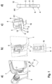
- FIGS. 3 A-C show various views of two variants (with and without holder support/twist-prevention stop VA) of a third embodiment, bent in strip development, of a resetting spring assembly with tangentially outwardly bent axial spring leg (space saving for combination brake calipers actuatable by a combination of electromechanical and hydraulic means) including floating shoe, partially with sketches of associated peripheral components;
- FIGS. 4 A-C and FIGS. 5 A-C show a variant as in FIG. 3 in supplementary illustrations
- FIGS. 6 A-C show the spring variant as in FIG. 1 , supplemented with bearing and force attack points in the respective spatial axes, and additionally a schematic spring characteristic curve diagram;
- FIGS. 7 A-F show in stage sketches a schematically illustrated spring deformation
- FIG. 8 is an illustration of a force-free spring contour (finished part, side view), and for comparison in projection the elastically preloaded, deformed spring contour immediately after brake assembly;
- FIGS. 9 A-B show in A) an illustration of the nominal spring contour immediately in installation position, and B) the elastically and plastically deformed spring contour after approximately 15 mm of brake lining wear;
- FIGS. 10 + 11 show various exemplary derivatives of the first embodiment
- FIG. 12 shows a diagram to illustrate the spring system behavior, where a resetting spring force F in the axially directed spatial direction is shown over a back plate shift in the axial spatial direction;
- FIG. 13 is a diagram similar to FIG. 12 to illustrate the spring system behavior, wherein however the radial spring force component is shown.
- FIG. 14 is a diagram to illustrate the spring system behavior, wherein the radial spring force component is illustrated in relation to a radially directed back plate shift.
- One embodiment of the invention includes a disc brake lining assembly 1 comprising friction material 2 which is fixed on the front side of a back plate 3 , and with a friction lining resetting spring 4 which is fixed on the rear side of the back plate 3 , wherein the friction lining resetting spring 4 has a base 5 and an adjoining elastic resetting spring bow 6 , and wherein the resetting spring bow 6 is suitable and intended for sitting on an assigned abutment 7 of a stator/holder 8 .
- the stator/holder 8 may be a brake holder mounted rotationally fixedly, i.e.
- a sliding caliper brake housing 19 which, additionally or separately, may comprise an electric motor-gear unit 20 in addition to hydraulic application means.
- the disclosed embodiment uses a feature combination in which the friction lining resetting spring 4 with its base 5 is fixedly mounted in relation to the friction linings, and the spring property is achieved by means of an additively composed spring characteristic curve which additively combines a plurality of portions (A, B, C, D), comprising a plurality of quasi-linearly growing straight portions A, C, D and, interposed in-between, at least one degressively curved transition portion B, and wherein the portions A-D each comprise mutually differently defined gradient angles ⁇ , ⁇ , ⁇ , ⁇ .
- portions A-D there is at least one part or characteristic curve portion B, C, D which is designed at least partially plastically deformable and which, because of its predetermined defined plastic deformation behavior, serves to automatically allow defined appropriate resetting springing including wear compensation (friction lining+brake disc).
- the particular advantage of an aspect of the invention is that the disc brake lining 1 and friction lining resetting spring 4 can always be exchanged together, i.e. particularly efficiently, with the positive effect that the incorrect mounting of the resetting spring means is impossible, and unacceptable reuse of worn resetting springs is also impossible, wherein the pre-mounted resetting spring means according to an aspect of the invention always remains easily and properly recyclable with the metallic recyclable materials of the disc brake linings.
- An aspect of the invention is indeed preferably presented here primarily in conjunction with an application example of a totally non-releasably structured rivet fixing between the back plate and resetting spring assembly, but on the basis of a sufficiently secured fixing, in principle a releasably arranged spring variant is also conceivable without leaving the principles of an aspect of the present invention.
- a resetting spring bow 6 is bent in a bow form pointing radially inward in relation to a radial direction R and is fixed on the motor vehicle disc brake lining 1 via the base 5 , a space-saving premounted friction lining assembly is presented which is efficiently bundled and resistant to incorrect installation.
- An alternative adaptation is that the resetting spring bow 6 is bent pointing outward in the tangential direction T. All these alternatives or designs can in principle be used variably for compact integration for both the electromechanical brake with MGU 20 and also for the combination brake with a combination of hydraulic and electromechanical actuation, and in particular also for motor vehicle disc brakes actuated exclusively hydraulically.
- a particularly robust resetting spring bow design 6 is provided which is resistant to alternating bending loads when curved by strain-hardening.
- the friction lining resetting spring 4 is cut from flat stainless steel material (stainless steel sheet), wherein at least some assembly parts for the purpose of spring characteristic curve modification may be provided partially or completely as a closed frame with at least one passage opening 9 and/or with at least one profiling 10 open at the edge.
- a multifunctional resetting spring assembly allows rational logistics with simplified handling and effectively reduced use of material, in that the base 5 is defined largely centrally riveted to the friction lining resetting spring, and wherein the radially pointing end piece of the friction lining resetting spring with resetting spring bow starts from one side thereof, and diametrically opposite this, a diametrically opposite end piece of the spring assembly is defined for an integrated radial spring component 11 and/or an integrated tangential spring component 13 , spring components 11 and/or 13 including one and/or several additional spring bows 12 and/or 14 , respectively.
- the strip development of a cut blank is flat for the sake of simplicity, and flat and tongue-shaped with organically attached additional spring bow 12 .
- a disc brake is possible in which a radial spring component 11 and/or a tangential spring component 13 is integrated in the force flow between the motor vehicle disc brake lining 1 and the holder 8 via the spring assembly.
- the mutual support may comprise a transversely oriented, and in particular relatively displaceable coupling between the spring assembly and holder 8 .
- a dynamically movable spring seat may be defined in the support on the abutment 7 .
- An improved static support on the abutment 7 is also possible if the spring assembly forms at least one sliding shoe 15 and/or at least one floating shoe 16 .
- Said sliding shoe 15 is here particularly advantageously characterized by reproducible relative displaceability (slide friction improvement), whereas a floating or roller shoe 16 offers quite particular advantages of insensitivity to corrosion due to the self-cleaning properties.
- an installation space reduction and/or raw material utilization is rationally improved if an additional spring component is integrally combined on the resetting spring assembly, in that the spring component branches from the spring assembly as a separate spring bow. This is achieved for example if the spring component and resetting spring bow are bent offset orthogonally to one another in the blank strip development. Furthermore, an aspect of the invention allows the additional spring component to branch from the base 5 and/or from the resetting spring bow 6 of the spring assembly.
- a particularly efficient embodiment of the spring assembly is defined in that in the projected shadow form, said assembly has a substantially G-shaped, screw-curved bent silhouette, and comprising two spring components 11 , 13 including shoes 15 , 16 with force effects oriented orthogonally to one another; one in the radial direction R and the other in the axial direction Ax.
Landscapes
- Engineering & Computer Science (AREA)
- General Engineering & Computer Science (AREA)
- Mechanical Engineering (AREA)
- Braking Arrangements (AREA)
Abstract
Description
-
- 1 Disc brake lining
- 2 Friction material
- 3 Back plate
- 4 Friction lining resetting spring
- 5 Base
- 6 Resetting spring bow
- 7 Abutment
- 8 Holder
- 9 Passage opening
- 10 Profiling (open at edge)
- 11 Radial spring component
- 12 Spring bow
- 13 Tangential spring component
- 14 Spring bow
- 15 Sliding shoe
- 16 Floating shoe
- 17 Blade/scoop
- 18 Twist prevention stop/support (VA)
- 19 Sliding caliper brake housing
- 20 MGU (electric motor-gear unit)
- A,B,C,D Portion
- α,β,γ,δ Gradient angle
- T Tangential direction
- R Radial direction
- Ax Axial direction (parallel to a theoretical wheel rotational axis Z)
- RS Friction lining centre of gravity (theoretical resulting friction force attack point)
- H1 Tangential bending axis
- H2 Radial bending axis
Claims (17)
Applications Claiming Priority (5)
| Application Number | Priority Date | Filing Date | Title |
|---|---|---|---|
| DE102019205625.3 | 2019-04-17 | ||
| DE102019205625 | 2019-04-17 | ||
| DE102019212896.3 | 2019-08-28 | ||
| DE102019212896.3A DE102019212896A1 (en) | 2019-04-17 | 2019-08-28 | Motor vehicle disc brake lining with friction lining return spring assembly |
| PCT/EP2020/059518 WO2020212169A1 (en) | 2019-04-17 | 2020-04-03 | Motor vehicle disc brake lining with friction lining resetting spring |
Publications (2)
| Publication Number | Publication Date |
|---|---|
| US20220205500A1 US20220205500A1 (en) | 2022-06-30 |
| US12228184B2 true US12228184B2 (en) | 2025-02-18 |
Family
ID=72660438
Family Applications (1)
| Application Number | Title | Priority Date | Filing Date |
|---|---|---|---|
| US17/602,479 Active 2041-03-31 US12228184B2 (en) | 2019-04-17 | 2020-04-03 | Motor vehicle disc brake lining with friction lining resetting spring |
Country Status (7)
| Country | Link |
|---|---|
| US (1) | US12228184B2 (en) |
| EP (1) | EP3956582B1 (en) |
| KR (1) | KR102698602B1 (en) |
| CN (1) | CN113692500B (en) |
| DE (1) | DE102019212896A1 (en) |
| PL (1) | PL3956582T3 (en) |
| WO (1) | WO2020212169A1 (en) |
Families Citing this family (5)
| Publication number | Priority date | Publication date | Assignee | Title |
|---|---|---|---|---|
| FR3097923B1 (en) * | 2019-06-26 | 2022-07-29 | Foundation Brakes France | "Disc brake comprising at least one elastic return spring of a brake pad, elastic return spring, replacement kit and mounting method" |
| DE102019210316A1 (en) * | 2019-07-12 | 2021-01-14 | Zf Active Safety Gmbh | Braking device for a motor vehicle with a reset device |
| FR3127791B1 (en) * | 2021-10-04 | 2023-11-24 | Hitachi Astemo France | SKATE SPRING FOR SKATE REMOVAL, SKATE ASSEMBLY AND GUIDANCE |
| DE102022200654A1 (en) * | 2022-01-20 | 2023-07-20 | Hl Mando Corporation | Brake pad arrangement with a pad spring for a disc brake system and disc brake system |
| KR20240178552A (en) * | 2023-06-22 | 2024-12-31 | 에이치엘만도 주식회사 | Retraction spring and caliper brake comprising the same |
Citations (36)
| Publication number | Priority date | Publication date | Assignee | Title |
|---|---|---|---|---|
| DE3023103A1 (en) | 1979-06-20 | 1981-01-08 | Tokico Ltd | DISC BRAKE |
| EP0100273A1 (en) | 1982-07-22 | 1984-02-08 | BENDIX France | Shoe spring for a caliper disc brake, and disc brake provided with the same |
| JPH01188729A (en) | 1988-01-20 | 1989-07-28 | Tokico Ltd | disc brake |
| DE4110850A1 (en) | 1991-04-04 | 1992-10-08 | Teves Gmbh Alfred | FLOATING SADDLE PARTIAL DISC BRAKE WITH ACTIVE RESETTING BRAKE SHOES |
| WO1995003499A1 (en) | 1993-07-26 | 1995-02-02 | Itt Automotive Europe Gmbh | Holding-down spring for disk brakes |
| US5388670A (en) * | 1993-07-26 | 1995-02-14 | Alliedsignal Inc. | Wear-limit warning anti-rattle spring |
| JPH0725342U (en) | 1993-10-20 | 1995-05-12 | 曙ブレーキ工業株式会社 | Pad clip with pad return mechanism |
| JP2002174276A (en) | 2000-12-04 | 2002-06-21 | Aisin Seiki Co Ltd | Disc brake |
| US6527090B1 (en) * | 1999-10-26 | 2003-03-04 | Robert Bosch Gmbh | Guiding spring for friction elements and disc brake comprising same |
| US20040222053A1 (en) * | 2001-09-25 | 2004-11-11 | Jonathan Wemple | Pad retraction spring for a brake shoe assembly and a disc brake assembly |
| JP2009041769A (en) | 2007-07-17 | 2009-02-26 | Hitachi Ltd | Disc brake |
| JP2010169149A (en) | 2009-01-21 | 2010-08-05 | Hitachi Automotive Systems Ltd | Disc brake |
| JP2011094696A (en) | 2009-10-29 | 2011-05-12 | Hitachi Automotive Systems Ltd | Disk brake |
| WO2011126125A1 (en) | 2010-04-09 | 2011-10-13 | 曙ブレーキ工業株式会社 | Floating disc brake, method of assembling same, and assemblies consisting of pad clips and return springs |
| JP2012063014A (en) | 2011-11-21 | 2012-03-29 | Hitachi Automotive Systems Ltd | Disc brake |
| EP2411694B1 (en) | 2009-03-25 | 2013-01-23 | Continental Teves AG & Co. oHG | Partially lined disc brake having a spring arrangement for clearance improvement and spring arrangement |
| DE102012006082A1 (en) | 2012-03-26 | 2013-09-26 | Knorr-Bremse Systeme für Nutzfahrzeuge GmbH | Disc brake with reset device and corresponding brake pad |
| DE102013208001A1 (en) | 2012-06-06 | 2013-12-12 | Continental Teves Ag & Co. Ohg | Fist saddle type disk brake for vehicle, has pivot bearing defining pivot axis, which is arranged orthogonal to axial direction such that rotary assembly and/or disassembly is enabled around pivot axis between disk brake and diaphragm |
| EP2775159A1 (en) | 2013-03-06 | 2014-09-10 | Hitachi Automotive Systems, Ltd. | Disc brake |
| DE102013207424A1 (en) | 2013-04-24 | 2014-10-30 | Continental Teves Ag & Co. Ohg | Partial lining disc brake with a spring arrangement for Lüftspielverbesserung and spring arrangement |
| US20140339026A1 (en) | 2013-05-14 | 2014-11-20 | Akebono Brake Corporation | Coiled spreader spring |
| CN104583635A (en) | 2012-08-23 | 2015-04-29 | 卢卡斯汽车股份有限公司 | Return spring and disc brake for motor vehicles comprising plastically deformable return spring |
| DE112013004669T5 (en) | 2012-09-25 | 2015-07-09 | Hitachi Automotive Systems, Ltd. | disc brake |
| DE202015104454U1 (en) | 2014-08-25 | 2015-10-08 | Akebono Brake Industry Co., Ltd. | Multi-part pad clip |
| CN105822699A (en) | 2015-01-28 | 2016-08-03 | 英国美瑞特重型车制动系统有限公司 | Disc brake |
| WO2016135118A1 (en) | 2015-02-25 | 2016-09-01 | Foundation Brakes France | Disk brake comprising at least one improved resilient return spring for a brake shoe, resilient return spring, replacement kit and assembly method |
| DE102015111166A1 (en) | 2015-07-10 | 2017-01-12 | Knorr-Bremse Systeme für Nutzfahrzeuge GmbH | Adjustment device for a disc brake |
| WO2017060513A1 (en) | 2015-10-09 | 2017-04-13 | Knorr-Bremse Systeme für Nutzfahrzeuge GmbH | Brake carrier |
| JP2017133588A (en) | 2016-01-27 | 2017-08-03 | 日立オートモティブシステムズ株式会社 | Disc brake |
| DE102016202520A1 (en) | 2016-02-18 | 2017-08-24 | Continental Teves Ag & Co. Ohg | Friction lining arrangement with restoring spring for clearance simulation for a motor vehicle part lining disc brake |
| CN107429766A (en) | 2015-01-30 | 2017-12-01 | 福乐尼·乐姆宝公开有限公司 | Spacer and spring assembly for disc brake calipers |
| DE102016211147A1 (en) | 2016-06-22 | 2017-12-28 | Volkswagen Aktiengesellschaft | disc brake |
| US10030729B2 (en) * | 2014-10-10 | 2018-07-24 | Chassis Brakes International B.V. | Return spring of a brake shoe including wear play compensation means, disk brake and replacement kit |
| US20180355932A1 (en) | 2015-06-12 | 2018-12-13 | Lucas Automotive Gmbh | Disc Brake For A Motor Vehicle and Brake Pad Assembly Therefor |
| DE102017113399A1 (en) | 2017-06-19 | 2018-12-20 | Knorr-Bremse Systeme für Nutzfahrzeuge GmbH | Arrangement of a displaceable brake disc and a hub of a disc brake |
| FR3089268A1 (en) | 2018-11-29 | 2020-06-05 | Foundation Brakes France | Brake pad return spring with hardened clamp |
Family Cites Families (1)
| Publication number | Priority date | Publication date | Assignee | Title |
|---|---|---|---|---|
| JPS5916875B2 (en) * | 1980-11-18 | 1984-04-18 | 株式会社神戸製鋼所 | Low hydrogen coated arc welding rod |
-
2019
- 2019-08-28 DE DE102019212896.3A patent/DE102019212896A1/en active Pending
-
2020
- 2020-04-03 KR KR1020217032396A patent/KR102698602B1/en active Active
- 2020-04-03 CN CN202080029354.2A patent/CN113692500B/en active Active
- 2020-04-03 EP EP20717160.4A patent/EP3956582B1/en active Active
- 2020-04-03 WO PCT/EP2020/059518 patent/WO2020212169A1/en not_active Ceased
- 2020-04-03 US US17/602,479 patent/US12228184B2/en active Active
- 2020-04-03 PL PL20717160.4T patent/PL3956582T3/en unknown
Patent Citations (57)
| Publication number | Priority date | Publication date | Assignee | Title |
|---|---|---|---|---|
| DE3023103A1 (en) | 1979-06-20 | 1981-01-08 | Tokico Ltd | DISC BRAKE |
| US4364455A (en) | 1979-06-20 | 1982-12-21 | Tokico Ltd. | Retraction spring for disc brake pads |
| EP0100273A1 (en) | 1982-07-22 | 1984-02-08 | BENDIX France | Shoe spring for a caliper disc brake, and disc brake provided with the same |
| US4515249A (en) | 1982-07-22 | 1985-05-07 | Societe Anonyme D.B.A. | Spring for pads of a disc brake with a sliding calliper, and disc brake equipped with such a spring |
| JPH01188729A (en) | 1988-01-20 | 1989-07-28 | Tokico Ltd | disc brake |
| DE4110850A1 (en) | 1991-04-04 | 1992-10-08 | Teves Gmbh Alfred | FLOATING SADDLE PARTIAL DISC BRAKE WITH ACTIVE RESETTING BRAKE SHOES |
| US5284228A (en) | 1991-04-04 | 1994-02-08 | Alfred Teves Gmbh | Floating-caliper spot-type disc brake with actively restored brake shoes |
| US5388670A (en) * | 1993-07-26 | 1995-02-14 | Alliedsignal Inc. | Wear-limit warning anti-rattle spring |
| WO1995003499A1 (en) | 1993-07-26 | 1995-02-02 | Itt Automotive Europe Gmbh | Holding-down spring for disk brakes |
| JPH0725342U (en) | 1993-10-20 | 1995-05-12 | 曙ブレーキ工業株式会社 | Pad clip with pad return mechanism |
| US6527090B1 (en) * | 1999-10-26 | 2003-03-04 | Robert Bosch Gmbh | Guiding spring for friction elements and disc brake comprising same |
| JP2002174276A (en) | 2000-12-04 | 2002-06-21 | Aisin Seiki Co Ltd | Disc brake |
| US20040222053A1 (en) * | 2001-09-25 | 2004-11-11 | Jonathan Wemple | Pad retraction spring for a brake shoe assembly and a disc brake assembly |
| JP2009041769A (en) | 2007-07-17 | 2009-02-26 | Hitachi Ltd | Disc brake |
| US8540060B2 (en) | 2009-01-21 | 2013-09-24 | Hitachi Automotive Systems, Ltd. | Disk brake |
| JP2010169149A (en) | 2009-01-21 | 2010-08-05 | Hitachi Automotive Systems Ltd | Disc brake |
| US8636119B2 (en) | 2009-03-25 | 2014-01-28 | Continental Teves Ag & Co. Ohg | Partially lined disk brake having a spring arrangement for improved clearance and spring arrangement |
| EP2411694B1 (en) | 2009-03-25 | 2013-01-23 | Continental Teves AG & Co. oHG | Partially lined disc brake having a spring arrangement for clearance improvement and spring arrangement |
| JP2011094696A (en) | 2009-10-29 | 2011-05-12 | Hitachi Automotive Systems Ltd | Disk brake |
| US8869950B2 (en) | 2010-04-09 | 2014-10-28 | Akebono Brake Industry Co., Ltd. | Floating disc brake, method of assembling same, and assemblies consisting of pad clips and return springs |
| WO2011126125A1 (en) | 2010-04-09 | 2011-10-13 | 曙ブレーキ工業株式会社 | Floating disc brake, method of assembling same, and assemblies consisting of pad clips and return springs |
| JP5184693B2 (en) | 2011-11-21 | 2013-04-17 | 日立オートモティブシステムズ株式会社 | Disc brake |
| JP2012063014A (en) | 2011-11-21 | 2012-03-29 | Hitachi Automotive Systems Ltd | Disc brake |
| DE102012006082A1 (en) | 2012-03-26 | 2013-09-26 | Knorr-Bremse Systeme für Nutzfahrzeuge GmbH | Disc brake with reset device and corresponding brake pad |
| EP2644926A1 (en) | 2012-03-26 | 2013-10-02 | KNORR-BREMSE Systeme für Nutzfahrzeuge GmbH | Disc brake comprising a reset mechanism, and corresponding brake lining |
| DE102013208001A1 (en) | 2012-06-06 | 2013-12-12 | Continental Teves Ag & Co. Ohg | Fist saddle type disk brake for vehicle, has pivot bearing defining pivot axis, which is arranged orthogonal to axial direction such that rotary assembly and/or disassembly is enabled around pivot axis between disk brake and diaphragm |
| CN104583635A (en) | 2012-08-23 | 2015-04-29 | 卢卡斯汽车股份有限公司 | Return spring and disc brake for motor vehicles comprising plastically deformable return spring |
| US10495165B2 (en) | 2012-08-23 | 2019-12-03 | Lucas Automotive Gmbh | Disc brake for a motor vehicle, comprising a plastically deformable restoring spring, and restoring spring |
| US9528564B2 (en) | 2012-08-23 | 2016-12-27 | Lucas Automotive Gmbh | Disc brake for a motor vehicle, comprising a plastically deformable restoring spring, and restoring spring |
| US20150211589A1 (en) * | 2012-08-23 | 2015-07-30 | Lucas Automotive Gmbh | Disc Brake for a Motor Vehicle, Comprising a Plastically Deformable Restoring Spring, and Restoring Spring |
| DE112013004669T5 (en) | 2012-09-25 | 2015-07-09 | Hitachi Automotive Systems, Ltd. | disc brake |
| US20150247542A1 (en) * | 2012-09-25 | 2015-09-03 | Hitachi Automotive Systems, Ltd. | Disc brake |
| US9568059B2 (en) | 2012-09-25 | 2017-02-14 | Hitachi Automotive Systems, Ltd. | Disc brake |
| JP5916875B2 (en) | 2012-09-25 | 2016-05-11 | 日立オートモティブシステムズ株式会社 | Disc brake |
| EP2775159A1 (en) | 2013-03-06 | 2014-09-10 | Hitachi Automotive Systems, Ltd. | Disc brake |
| DE102013207424A1 (en) | 2013-04-24 | 2014-10-30 | Continental Teves Ag & Co. Ohg | Partial lining disc brake with a spring arrangement for Lüftspielverbesserung and spring arrangement |
| US20140339026A1 (en) | 2013-05-14 | 2014-11-20 | Akebono Brake Corporation | Coiled spreader spring |
| US9677629B2 (en) | 2014-08-25 | 2017-06-13 | Akebono Brake Industry Co., Ltd. | Multiple piece pad clip |
| DE202015104454U1 (en) | 2014-08-25 | 2015-10-08 | Akebono Brake Industry Co., Ltd. | Multi-part pad clip |
| US10030729B2 (en) * | 2014-10-10 | 2018-07-24 | Chassis Brakes International B.V. | Return spring of a brake shoe including wear play compensation means, disk brake and replacement kit |
| CN105822699A (en) | 2015-01-28 | 2016-08-03 | 英国美瑞特重型车制动系统有限公司 | Disc brake |
| US9869357B2 (en) | 2015-01-28 | 2018-01-16 | Meritor Heavy Vehicle Braking Systems (Uk) Limited | Disc brake |
| CN107429766A (en) | 2015-01-30 | 2017-12-01 | 福乐尼·乐姆宝公开有限公司 | Spacer and spring assembly for disc brake calipers |
| US10697504B2 (en) | 2015-01-30 | 2020-06-30 | Freni Brembo S.P.A. | Pad and spring assembly for a disc brake caliper |
| WO2016135118A1 (en) | 2015-02-25 | 2016-09-01 | Foundation Brakes France | Disk brake comprising at least one improved resilient return spring for a brake shoe, resilient return spring, replacement kit and assembly method |
| US20180355932A1 (en) | 2015-06-12 | 2018-12-13 | Lucas Automotive Gmbh | Disc Brake For A Motor Vehicle and Brake Pad Assembly Therefor |
| US10982729B2 (en) | 2015-07-10 | 2021-04-20 | Knorr-Bremse Systeme Fuer Nutzfahrzeuge Gmbh | Adjusting device for a disc brake |
| DE102015111166A1 (en) | 2015-07-10 | 2017-01-12 | Knorr-Bremse Systeme für Nutzfahrzeuge GmbH | Adjustment device for a disc brake |
| WO2017060513A1 (en) | 2015-10-09 | 2017-04-13 | Knorr-Bremse Systeme für Nutzfahrzeuge GmbH | Brake carrier |
| US10738844B2 (en) | 2015-10-09 | 2020-08-11 | Knorr-Bremse Systeme Fuer Nutzfahrzeuge Gmbh | Disc brake for a utility vehicle |
| JP2017133588A (en) | 2016-01-27 | 2017-08-03 | 日立オートモティブシステムズ株式会社 | Disc brake |
| KR20180108826A (en) | 2016-02-18 | 2018-10-04 | 콘티넨탈 테베스 아게 운트 코. 오하게 | A friction lining assembly having a restoring spring for restricting a gap for a partially lined disc brake of an automobile |
| DE102016202520A1 (en) | 2016-02-18 | 2017-08-24 | Continental Teves Ag & Co. Ohg | Friction lining arrangement with restoring spring for clearance simulation for a motor vehicle part lining disc brake |
| US11209056B2 (en) | 2016-02-18 | 2021-12-28 | Continental Teves Ag & Co. Ohg | Friction lining assembly having a restoring spring for limiting clearance for a motor-vehicle partially lined disk brake |
| DE102016211147A1 (en) | 2016-06-22 | 2017-12-28 | Volkswagen Aktiengesellschaft | disc brake |
| DE102017113399A1 (en) | 2017-06-19 | 2018-12-20 | Knorr-Bremse Systeme für Nutzfahrzeuge GmbH | Arrangement of a displaceable brake disc and a hub of a disc brake |
| FR3089268A1 (en) | 2018-11-29 | 2020-06-05 | Foundation Brakes France | Brake pad return spring with hardened clamp |
Non-Patent Citations (7)
| Title |
|---|
| Chinese Notice of Allowance for Chinese Application No. 202080029354.2, dated May 18, 2023 with partial translation, 7 pages. |
| Chinese Office Action for Chinese Application No. 202080029354.2, dated Nov. 2, 2022 with translation, 18 pages. |
| European Examination Report for EP Application No. 20717160.4, dated Jul. 6, 2023 with translation, 9 pages. |
| German Examination Report for German Application No. 10 2019 212 896.3, dated Sep. 29, 2021 with translation, 16 pages. |
| International Search Report and Written Opinion for International Application No. PCT/EP2020/059518, mailed Jun. 22, 2020, with partial English translation, 9 pages,. |
| Korean Request for Submission of an Opinion for Korean Application No. 10-2021-7032396, dated Feb. 27, 2023 with translation, 13 pages. |
| Office Action (Decision for Grant of Patent) issued May 31, 2024, by the Korean Intellectual Property Office in corresponding Korean Patent Application No. 10-2021-7032396 and an English translation of the Office Action. (6 pages). |
Also Published As
| Publication number | Publication date |
|---|---|
| US20220205500A1 (en) | 2022-06-30 |
| KR20210135583A (en) | 2021-11-15 |
| WO2020212169A1 (en) | 2020-10-22 |
| KR102698602B1 (en) | 2024-08-23 |
| EP3956582B1 (en) | 2025-03-05 |
| CN113692500B (en) | 2023-08-08 |
| PL3956582T3 (en) | 2025-10-06 |
| EP3956582A1 (en) | 2022-02-23 |
| CN113692500A (en) | 2021-11-23 |
| DE102019212896A1 (en) | 2020-10-22 |
Similar Documents
| Publication | Publication Date | Title |
|---|---|---|
| US12228184B2 (en) | Motor vehicle disc brake lining with friction lining resetting spring | |
| US10495165B2 (en) | Disc brake for a motor vehicle, comprising a plastically deformable restoring spring, and restoring spring | |
| US9657793B2 (en) | Friction lining with a steel wire bow spring | |
| US5934417A (en) | Disc brake return spring | |
| US5860495A (en) | Floating caliper-type disk brake for automotive vehicles | |
| KR102148589B1 (en) | Friction lining assembly with restoring spring to limit clearance for partially lined disc brakes in automobiles | |
| US10174799B2 (en) | Disk brake | |
| RU2655790C2 (en) | Disk brake and hold-down spring of such a disk brake | |
| EP2917604B1 (en) | Disc brake pad mounting and retention system | |
| JP4698147B2 (en) | Disc brake assembly | |
| EP3306128A1 (en) | A disc brake | |
| CN109838477B (en) | Disc brake | |
| CN107850151A (en) | Disk brake and its brake block component for motor vehicle | |
| US20190249731A1 (en) | Abutment clip for disk brakes | |
| CN109488708B (en) | Disc brake | |
| EP3150878B1 (en) | Brake assembly having a bridge | |
| CN114026348B (en) | Disc brake comprising at least one elastic return spring for a brake pad, elastic return spring, replacement kit and installation method | |
| US12516708B2 (en) | Motor vehicle disc brake friction lining with wire helical spring | |
| WO2008079087A1 (en) | Method and device for disc brakes and vehicle | |
| US10724585B2 (en) | Brake pad | |
| CN117795224A (en) | Disc brakes for commercial vehicles and brake linings for disc brakes | |
| CN108980237B (en) | Disc brake | |
| US8151949B2 (en) | Drum brake apparatus | |
| CN114278682A (en) | Return spring body, fixed brake caliper and vehicle |
Legal Events
| Date | Code | Title | Description |
|---|---|---|---|
| FEPP | Fee payment procedure |
Free format text: ENTITY STATUS SET TO UNDISCOUNTED (ORIGINAL EVENT CODE: BIG.); ENTITY STATUS OF PATENT OWNER: LARGE ENTITY |
|
| AS | Assignment |
Owner name: CONTINENTAL TEVES AG & CO. OHG, GERMANY Free format text: ASSIGNMENT OF ASSIGNORS INTEREST;ASSIGNORS:PETRI, RALPH;BASHAYAN, KILIAN;SALZMANN, SEBASTIAN;SIGNING DATES FROM 20210915 TO 20211109;REEL/FRAME:058592/0500 |
|
| STPP | Information on status: patent application and granting procedure in general |
Free format text: DOCKETED NEW CASE - READY FOR EXAMINATION |
|
| STPP | Information on status: patent application and granting procedure in general |
Free format text: NON FINAL ACTION MAILED |
|
| STPP | Information on status: patent application and granting procedure in general |
Free format text: RESPONSE TO NON-FINAL OFFICE ACTION ENTERED AND FORWARDED TO EXAMINER |
|
| STPP | Information on status: patent application and granting procedure in general |
Free format text: FINAL REJECTION MAILED |
|
| STPP | Information on status: patent application and granting procedure in general |
Free format text: RESPONSE AFTER FINAL ACTION FORWARDED TO EXAMINER |
|
| STPP | Information on status: patent application and granting procedure in general |
Free format text: ADVISORY ACTION MAILED |
|
| STPP | Information on status: patent application and granting procedure in general |
Free format text: NON FINAL ACTION MAILED |
|
| AS | Assignment |
Owner name: CONTINENTAL AUTOMOTIVE TECHNOLOGIES GMBH, GERMANY Free format text: MERGER AND CHANGE OF NAME;ASSIGNORS:CONTINENTAL TEVES AG & CO. OHG;CONTINENTAL AUTOMOTIVE TECHNOLOGIES GMBH;REEL/FRAME:068794/0001 Effective date: 20220714 |
|
| STPP | Information on status: patent application and granting procedure in general |
Free format text: RESPONSE TO NON-FINAL OFFICE ACTION ENTERED AND FORWARDED TO EXAMINER |
|
| STPP | Information on status: patent application and granting procedure in general |
Free format text: NOTICE OF ALLOWANCE MAILED -- APPLICATION RECEIVED IN OFFICE OF PUBLICATIONS |
|
| STPP | Information on status: patent application and granting procedure in general |
Free format text: PUBLICATIONS -- ISSUE FEE PAYMENT VERIFIED |
|
| STCF | Information on status: patent grant |
Free format text: PATENTED CASE |