US1221237A - Gate-hanger. - Google Patents
Gate-hanger. Download PDFInfo
- Publication number
- US1221237A US1221237A US9962516A US9962516A US1221237A US 1221237 A US1221237 A US 1221237A US 9962516 A US9962516 A US 9962516A US 9962516 A US9962516 A US 9962516A US 1221237 A US1221237 A US 1221237A
- Authority
- US
- United States
- Prior art keywords
- gate
- frame
- hanger
- arms
- bar
- Prior art date
- Legal status (The legal status is an assumption and is not a legal conclusion. Google has not performed a legal analysis and makes no representation as to the accuracy of the status listed.)
- Expired - Lifetime
Links
- 241001125879 Gobio Species 0.000 description 6
- 238000010276 construction Methods 0.000 description 1
- 239000000945 filler Substances 0.000 description 1
- HJHVQCXHVMGZNC-JCJNLNMISA-M sodium;(2z)-2-[(3r,4s,5s,8s,9s,10s,11r,13r,14s,16s)-16-acetyloxy-3,11-dihydroxy-4,8,10,14-tetramethyl-2,3,4,5,6,7,9,11,12,13,15,16-dodecahydro-1h-cyclopenta[a]phenanthren-17-ylidene]-6-methylhept-5-enoate Chemical compound [Na+].O[C@@H]([C@@H]12)C[C@H]3\C(=C(/CCC=C(C)C)C([O-])=O)[C@@H](OC(C)=O)C[C@]3(C)[C@@]2(C)CC[C@@H]2[C@]1(C)CC[C@@H](O)[C@H]2C HJHVQCXHVMGZNC-JCJNLNMISA-M 0.000 description 1
Images

Classifications
-
- E—FIXED CONSTRUCTIONS
- E06—DOORS, WINDOWS, SHUTTERS, OR ROLLER BLINDS IN GENERAL; LADDERS
- E06B—FIXED OR MOVABLE CLOSURES FOR OPENINGS IN BUILDINGS, VEHICLES, FENCES OR LIKE ENCLOSURES IN GENERAL, e.g. DOORS, WINDOWS, BLINDS, GATES
- E06B11/00—Means for allowing passage through fences, barriers or the like, e.g. stiles
- E06B11/02—Gates; Doors
- E06B11/04—Gates; Doors characterised by the kind of suspension
Definitions
- the device forming the subject matter of this application iS a ate, and the invention aims to provide nove means for supporting the gate for swinging movement and for sliding movement, selectively, at the will of an operator. 1t is within the province of the disclosure to improve generally and to enhance the utility of devices of that type to which the present invention appertains.
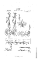
- FIG. 1 shows in side elevation, constructed in accordance with the invention, parts being broken away;
- Fig. 2 is a cross section on the line 2-2 of Fig. 1;
- Fig. 3 is a fragmental top plan of the gate, the support or post being shown in section, the gate being in the position which it will assume when it is manipulated as a sliding gate; n
- Fig. 4 is a view similar to Fig. 3, but showing the gate positioned for use as a swinging gate;
- Fig. 5 is a fragmental top plan of the gate, showing the same swung from the position of Fig. 4, the support or post appeara gate present ingrin section;
- ig. 6 is a fragmental sectional detail illustrating one of the gate directing rollers and its mounting.
- the numeral 1 indicates a support which may be a post, and the numeral 2 denotes generally, a gate which may be of any desired form. 1n the present instance, the
- gate 2 is shown as comprising end bars 3 and 4 connected by slats 5.
- Rearwardly projecting gudgeons 6 are mounted diago- Specicaticn of Letters Patent.
- This frame includes an upright bar 8 located on one side of the Oate 2 and an u )riO'ht stri 3 9 located on the other side of the gate.
- An arched bracket 10 lies on one side of the gate 2 and constitutes a part of the frame above alluded to, the bracket 10 including horizontal arms 11 which extend across the strip 9 to the rear thereof.
- Securing elements 12 unite the upper and lower ends of the strip 9 with the arms 11 of the bracket 1() and withthe bar 8.
- On the securing elements 12 are mounted fillers 14 interposed between the arms 11 and the bar 8.
- an arched bracket 15 including arms 16,v offset as shown at 17 to coperate with the bar 8, and terminating in extensions 18 which project toward the post 1 beyond the bar 8, as will be clearly understood from Figs. 3 and 4.
- the extensions 18 terminate in eyes 19 receiving the pintles 7 of the gudgeons 6, and thus the gate supporting frame may be swung on the gudgeons.
- Adjacent their upper and lower ends, the strip 9 and the bar 8 are connected by shafts 22 carrying rollers 23 coacting respectively with upper and lower edges of certain of the slats 5 of the gate 2.
- a roller 26 engages the lower edge of one of the slats 5 of the gate.
- the brackets 10 and 15 are provided with alined holes 27.
- the shaft 24 may be mounted in the holes 27 when desired.
- the gate 2 in the drawings is shown as mounted to swing on the left hand post. When it is desired to mount the gate to swing on the right hand post, the gate is turned end for end, and is turned up side down. Then the shaft 24 is Disiro
- brackets 10 and 15 may be connected by pins 28 carrying'spacing sleeves like the sleeves 25 in Fig. 6.
- the gate When the gate is in the positions of Figs. 1 and 3, the gate may be moved endwise and be made to operate as a sliding gate, the lrollers 26 and 23 serving to direct the movement of the gate.
- the gate also may be used as a swinging gate if desired.
- the gate may be slid or swung without difficulty.
- the gudgeons 6 project from the support 1 at an angle of approximately forty-five degreesV to the plane occupied by the gate when the gate is closed. Consequently, when the gate is fully opened, as shown in Fig. 5, the 'gate is housed behind the support 1. r
- Va support a frame hinged to the support; a roller; means for mounting the roller on the frame; and a gate mounted to swing with the frame on the support and including a bar mounted to slide on the roller; the frame being symmetrical with respect to a hori- Copies of this patent may be obtained for zontal axis to provide for an inversion and for an end for end reversal oiE the frame, thereby to suspend the gate for left hand swinging movement or for right hand swingcated to permit the roller to be disposed beneath the bar when the frame is inverted andturned end for end.
- a frame comprising U-shaped parts including upper and lower arms, the arms of one part being longer than the arms of the other part; means for connecting the parts of the frame; a connection uniting the arms of one part; a gate slidable between the parts of the CHARLES D. SMITH. Vitnesses E. A. TROVER, GEO. A. VAN DYKE.
Landscapes
- Engineering & Computer Science (AREA)
- Civil Engineering (AREA)
- Structural Engineering (AREA)
- Devices For Checking Fares Or Tickets At Control Points (AREA)
Description
C. D. SMITH.
GATE HANGER. APPLICATION FILED MAY 24. I9I6.
` mi Patentempr. 3,1917.
2 sHEEVTssIIEIir I.
l N 'o o o o o `0 s o AI `I1-ul A I" I" I( I IW I) V I-f Inventor C. D. SMITH.
GATE HANGER.
f APPLICATION FILED MAY 24, |916. LQQLQ' A Patented Apr, 3, 1917.
2 SHEETS-SHEET 2.
Inventor Attorneys CHARLES D. sivIITII, or PARIS, ILLINOIS, ASsIeNoR or @NE-HALF To cHARLns L. BROWN, or rARIs, ILLrNoIs.
GATE-HANGER.
Application filed May 24, 1916.
To all whom t may concern:
Be it known that I, .CHARLES D. SMITH, a citizen of the United States, residing at Paris, in the county of Edgar and State of Illinois, have invented a. new and useful Gate-Hanger, of which the following is a specification. y
The device forming the subject matter of this application iS a ate, and the invention aims to provide nove means for supporting the gate for swinging movement and for sliding movement, selectively, at the will of an operator. 1t is within the province of the disclosure to improve generally and to enhance the utility of devices of that type to which the present invention appertains.
With the above and other objects in View which will appear as the description proceeds, the invention resides in the combination and arrangement of parts and in the details of construction hereinafter described and claimed, it being understoodv that changes in the precise embodiment of the invention herein disclosed can be made within the scope of what is claimed, without departing from the spirit of the invention.
In the accompanying drawings Figure 1 shows in side elevation, constructed in accordance with the invention, parts being broken away;
Fig. 2 is a cross section on the line 2-2 of Fig. 1;
Fig. 3 is a fragmental top plan of the gate, the support or post being shown in section, the gate being in the position which it will assume when it is manipulated as a sliding gate; n
Fig. 4 is a view similar to Fig. 3, but showing the gate positioned for use as a swinging gate;
Fig. 5 is a fragmental top plan of the gate, showing the same swung from the position of Fig. 4, the support or post appeara gate present ingrin section;
ig. 6 is a fragmental sectional detail illustrating one of the gate directing rollers and its mounting.
The numeral 1 indicates a support which may be a post, and the numeral 2 denotes generally, a gate which may be of any desired form. 1n the present instance, the
gate 2 is shown as comprising end bars 3 and 4 connected by slats 5. Rearwardly projecting gudgeons 6 are mounted diago- Specicaticn of Letters Patent.
Patented Apr. e, Iers. Serial No. 99,625.
that swings on the gudgeons 6. This frame includes an upright bar 8 located on one side of the Oate 2 and an u )riO'ht stri 3 9 located on the other side of the gate. An arched bracket 10 lies on one side of the gate 2 and constitutes a part of the frame above alluded to, the bracket 10 including horizontal arms 11 which extend across the strip 9 to the rear thereof. Securing elements 12 unite the upper and lower ends of the strip 9 with the arms 11 of the bracket 1() and withthe bar 8. On the securing elements 12 are mounted fillers 14 interposed between the arms 11 and the bar 8. posed on the opposite side of the gate from the bracket 10 and constituting a part of the gate supporting frame is an arched bracket 15 including arms 16,v offset as shown at 17 to coperate with the bar 8, and terminating in extensions 18 which project toward the post 1 beyond the bar 8, as will be clearly understood from Figs. 3 and 4. The securing elements 12 hereinbefore alluded to enymembers 21. The extensions 18 terminate in eyes 19 receiving the pintles 7 of the gudgeons 6, and thus the gate supporting frame may be swung on the gudgeons. Adjacent their upper and lower ends, the strip 9 and the bar 8 are connected by shafts 22 carrying rollers 23 coacting respectively with upper and lower edges of certain of the slats 5 of the gate 2. Mounted in the curved portions of the brackets 10 and 15 is a shaft 24 carrying a rotatable sleeve 25 on which is journaled a roller 26. Such elements as the sleeve 2,5 may be used in connection with the rollers 23 hereinbefore mentioned. The roller 26 engages the lower edge of one of the slats 5 of the gate. Above the slat against which the roller 26 bears, the brackets 10 and 15 are provided with alined holes 27. The shaft 24 may be mounted in the holes 27 when desired. The gate 2 in the drawings is shown as mounted to swing on the left hand post. When it is desired to mount the gate to swing on the right hand post, the gate is turned end for end, and is turned up side down. Then the shaft 24 is Disiro
mounted in the holes 27 as hereinbefore mentioned. The brackets 10 and 15 may be connected by pins 28 carrying'spacing sleeves like the sleeves 25 in Fig. 6.
When the gate is in the positions of Figs. 1 and 3, the gate may be moved endwise and be made to operate as a sliding gate, the lrollers 26 and 23 serving to direct the movement of the gate. The gate also may be used as a swinging gate if desired.
Owing to the position of the gudgeons 6 on the post 1, and because of the oiisetting of the arms 16 as shown at 17, the gate may be slid or swung without difficulty.
The gudgeons 6 project from the support 1 at an angle of approximately forty-five degreesV to the plane occupied by the gate when the gate is closed. Consequently, when the gate is fully opened, as shown in Fig. 5, the 'gate is housed behind the support 1. r
v Having thus described the invention, what is claimed is l1. In a device of the class described, Va support; a frame hinged to the support; a roller; means for mounting the roller on the frame; and a gate mounted to swing with the frame on the support and including a bar mounted to slide on the roller; the frame being symmetrical with respect to a hori- Copies of this patent may be obtained for zontal axis to provide for an inversion and for an end for end reversal oiE the frame, thereby to suspend the gate for left hand swinging movement or for right hand swingcated to permit the roller to be disposed beneath the bar when the frame is inverted andturned end for end.
2. In a device of the class described, a frame comprising U-shaped parts including upper and lower arms, the arms of one part being longer than the arms of the other part; means for connecting the parts of the frame; a connection uniting the arms of one part; a gate slidable between the parts of the CHARLES D. SMITH. Vitnesses E. A. TROVER, GEO. A. VAN DYKE.
ive cents each, by addressing the Commissioner of Patents,
Washington, D. C.
ing movement, and said means being duplit
Priority Applications (1)
| Application Number | Priority Date | Filing Date | Title |
|---|---|---|---|
| US9962516A US1221237A (en) | 1916-05-24 | 1916-05-24 | Gate-hanger. |
Applications Claiming Priority (1)
| Application Number | Priority Date | Filing Date | Title |
|---|---|---|---|
| US9962516A US1221237A (en) | 1916-05-24 | 1916-05-24 | Gate-hanger. |
Publications (1)
| Publication Number | Publication Date |
|---|---|
| US1221237A true US1221237A (en) | 1917-04-03 |
Family
ID=3289102
Family Applications (1)
| Application Number | Title | Priority Date | Filing Date |
|---|---|---|---|
| US9962516A Expired - Lifetime US1221237A (en) | 1916-05-24 | 1916-05-24 | Gate-hanger. |
Country Status (1)
| Country | Link |
|---|---|
| US (1) | US1221237A (en) |
-
1916
- 1916-05-24 US US9962516A patent/US1221237A/en not_active Expired - Lifetime
Similar Documents
| Publication | Publication Date | Title |
|---|---|---|
| US506267A (en) | William e | |
| US1216794A (en) | Window-screen. | |
| US1221237A (en) | Gate-hanger. | |
| US1223639A (en) | Gate. | |
| US1144404A (en) | Hinge mechanism. | |
| US679822A (en) | Vehicle-door. | |
| US721600A (en) | Gate. | |
| US942228A (en) | Gate. | |
| US1203121A (en) | Hinge. | |
| US1129436A (en) | Silo. | |
| US724300A (en) | Dresser. | |
| US1093843A (en) | Stay-hinge. | |
| US599583A (en) | Stephen e | |
| US417335A (en) | Farm-gate | |
| US1265288A (en) | Farm-gate. | |
| US265526A (en) | Fence-gate | |
| US1151518A (en) | Folding gate. | |
| US777405A (en) | Gate. | |
| US946872A (en) | Sectional bookcase. | |
| US1154087A (en) | Door-brace. | |
| US184169A (en) | Improvement in clothes-driers | |
| US258624A (en) | Farm-gate | |
| US693971A (en) | Hinge device. | |
| US415264A (en) | Ventilator | |
| US985325A (en) | Gate. |