US12212181B2 - Microgrid power system - Google Patents
Microgrid power system Download PDFInfo
- Publication number
- US12212181B2 US12212181B2 US18/525,742 US202318525742A US12212181B2 US 12212181 B2 US12212181 B2 US 12212181B2 US 202318525742 A US202318525742 A US 202318525742A US 12212181 B2 US12212181 B2 US 12212181B2
- Authority
- US
- United States
- Prior art keywords
- battery
- power
- battery pack
- energy storage
- controller
- Prior art date
- Legal status (The legal status is an assumption and is not a legal conclusion. Google has not performed a legal analysis and makes no representation as to the accuracy of the status listed.)
- Active
Links
Images


Classifications
-
- H—ELECTRICITY
- H02—GENERATION; CONVERSION OR DISTRIBUTION OF ELECTRIC POWER
- H02J—ELECTRIC POWER NETWORKS; CIRCUIT ARRANGEMENTS OR SYSTEMS FOR SUPPLYING OR DISTRIBUTING ELECTRIC POWER; SYSTEMS FOR STORING ELECTRIC ENERGY
- H02J3/00—Circuit arrangements for AC mains or AC distribution networks
- H02J3/28—Arrangements for balancing of the load in networks by storage of energy
- H02J3/32—Arrangements for balancing of the load in networks by storage of energy using batteries or super capacitors with converting means
-
- H—ELECTRICITY
- H02—GENERATION; CONVERSION OR DISTRIBUTION OF ELECTRIC POWER
- H02J—ELECTRIC POWER NETWORKS; CIRCUIT ARRANGEMENTS OR SYSTEMS FOR SUPPLYING OR DISTRIBUTING ELECTRIC POWER; SYSTEMS FOR STORING ELECTRIC ENERGY
- H02J3/00—Circuit arrangements for AC mains or AC distribution networks
- H02J3/38—Arrangements for feeding a single network from two or more generators or sources in parallel; Arrangements for feeding already energised networks from additional generators or sources in parallel
- H02J3/381—Dispersed generators
-
- H02J7/0048—
-
- H—ELECTRICITY
- H02—GENERATION; CONVERSION OR DISTRIBUTION OF ELECTRIC POWER
- H02J—ELECTRIC POWER NETWORKS; CIRCUIT ARRANGEMENTS OR SYSTEMS FOR SUPPLYING OR DISTRIBUTING ELECTRIC POWER; SYSTEMS FOR STORING ELECTRIC ENERGY
- H02J7/00—Circuit arrangements for charging or discharging batteries or for supplying loads from batteries
- H02J7/02—Circuit arrangements for charging or discharging batteries or for supplying loads from batteries for charging batteries from AC mains by converters
-
- H—ELECTRICITY
- H02—GENERATION; CONVERSION OR DISTRIBUTION OF ELECTRIC POWER
- H02J—ELECTRIC POWER NETWORKS; CIRCUIT ARRANGEMENTS OR SYSTEMS FOR SUPPLYING OR DISTRIBUTING ELECTRIC POWER; SYSTEMS FOR STORING ELECTRIC ENERGY
- H02J7/00—Circuit arrangements for charging or discharging batteries or for supplying loads from batteries
- H02J7/80—Circuit arrangements for charging or discharging batteries or for supplying loads from batteries including monitoring or indicating arrangements
- H02J7/82—Control of state of charge [SOC]
-
- H—ELECTRICITY
- H02—GENERATION; CONVERSION OR DISTRIBUTION OF ELECTRIC POWER
- H02J—ELECTRIC POWER NETWORKS; CIRCUIT ARRANGEMENTS OR SYSTEMS FOR SUPPLYING OR DISTRIBUTING ELECTRIC POWER; SYSTEMS FOR STORING ELECTRIC ENERGY
- H02J2101/00—Supply or distribution of decentralised, dispersed or local electric power generation
- H02J2101/10—Dispersed power generation using fossil fuels, e.g. diesel generators
-
- H—ELECTRICITY
- H02—GENERATION; CONVERSION OR DISTRIBUTION OF ELECTRIC POWER
- H02J—ELECTRIC POWER NETWORKS; CIRCUIT ARRANGEMENTS OR SYSTEMS FOR SUPPLYING OR DISTRIBUTING ELECTRIC POWER; SYSTEMS FOR STORING ELECTRIC ENERGY
- H02J2101/00—Supply or distribution of decentralised, dispersed or local electric power generation
- H02J2101/20—Dispersed power generation using renewable energy sources
- H02J2101/22—Solar energy
- H02J2101/24—Photovoltaics
-
- H—ELECTRICITY
- H02—GENERATION; CONVERSION OR DISTRIBUTION OF ELECTRIC POWER
- H02J—ELECTRIC POWER NETWORKS; CIRCUIT ARRANGEMENTS OR SYSTEMS FOR SUPPLYING OR DISTRIBUTING ELECTRIC POWER; SYSTEMS FOR STORING ELECTRIC ENERGY
- H02J2101/00—Supply or distribution of decentralised, dispersed or local electric power generation
- H02J2101/20—Dispersed power generation using renewable energy sources
- H02J2101/28—Wind energy
-
- H—ELECTRICITY
- H02—GENERATION; CONVERSION OR DISTRIBUTION OF ELECTRIC POWER
- H02J—ELECTRIC POWER NETWORKS; CIRCUIT ARRANGEMENTS OR SYSTEMS FOR SUPPLYING OR DISTRIBUTING ELECTRIC POWER; SYSTEMS FOR STORING ELECTRIC ENERGY
- H02J2103/00—Details of circuit arrangements for mains or AC distribution networks
- H02J2103/30—Simulating, planning, modelling, reliability check or computer assisted design [CAD] of electric power networks
- H02J2103/35—Grid-level management of power transmission or distribution systems, e.g. load flow analysis or active network management
-
- H02J2300/10—
-
- H02J2300/24—
-
- H02J2300/28—
-
- H—ELECTRICITY
- H02—GENERATION; CONVERSION OR DISTRIBUTION OF ELECTRIC POWER
- H02J—ELECTRIC POWER NETWORKS; CIRCUIT ARRANGEMENTS OR SYSTEMS FOR SUPPLYING OR DISTRIBUTING ELECTRIC POWER; SYSTEMS FOR STORING ELECTRIC ENERGY
- H02J9/00—Circuit arrangements for emergency or stand-by power supply, e.g. for emergency lighting
- H02J9/04—Circuit arrangements for emergency or stand-by power supply, e.g. for emergency lighting in which the distribution system is disconnected from the normal source and connected to a standby source
- H02J9/06—Circuit arrangements for emergency or stand-by power supply, e.g. for emergency lighting in which the distribution system is disconnected from the normal source and connected to a standby source with automatic change-over, e.g. UPS systems
-
- Y—GENERAL TAGGING OF NEW TECHNOLOGICAL DEVELOPMENTS; GENERAL TAGGING OF CROSS-SECTIONAL TECHNOLOGIES SPANNING OVER SEVERAL SECTIONS OF THE IPC; TECHNICAL SUBJECTS COVERED BY FORMER USPC CROSS-REFERENCE ART COLLECTIONS [XRACs] AND DIGESTS
- Y02—TECHNOLOGIES OR APPLICATIONS FOR MITIGATION OR ADAPTATION AGAINST CLIMATE CHANGE
- Y02E—REDUCTION OF GREENHOUSE GAS [GHG] EMISSIONS, RELATED TO ENERGY GENERATION, TRANSMISSION OR DISTRIBUTION
- Y02E10/00—Energy generation through renewable energy sources
- Y02E10/50—Photovoltaic [PV] energy
- Y02E10/56—Power conversion systems, e.g. maximum power point trackers
Definitions
- the present disclosure generally relates to electrical energy generation, storage, and distribution; and more particularly, to a microgrid power system for providing power to residences and businesses, especially those unserved or underserved by established utility infrastructure.
- Embodiments of the present invention include a microgrid power system having one or more power stations (i.e., off-site power) and one or more local power systems (i.e., on-site power or load centers) connected to the power stations to provide power to a local load.
- the local power system is configured to provide electrical power to a home, apartment building, office building, or factory, for example.
- the local power system will receive power from one or more power stations to power the local load and/or to charge a local battery.
- the local power system will use the local battery to power the load.
- the local power system will use a combination of the local battery and power from a power station to power the load.
- the power station may generate power from solar sources (e.g., photovoltaic), wind sources, hydroelectric sources, or internal combustion engine sources (e.g., a diesel generator), and may also include a battery to store and later source power.
- the local power system includes a battery, a first switch, a phase sensor, a bidirectional power converter, and a controller.
- the first switch connects a first AC power from an off-site power station to a local load.
- the phase sensor senses a phase of the first AC power.
- the bidirectional power converter is coupled to the power station, to the battery, and to the load.
- the power converter is configured to selectively convert DC power from the battery to a second AC power, and to selectively convert the first AC power to DC power to charge the battery.
- the controller controls the first switch to selectively provide the first AC power to the load when power from the power station is desired.
- the controller controls the power converter to provide DC power from the power converter to the battery to charge the battery from the first AC power, when battery charging is desired.
- the controller further controls the power converter to provide the second AC power to the load when battery power is desired.
- the controller compares the phase of the first AC power to a phase of the second AC power, adjusts the phase of the second AC power, and closes the first switch only when the phase of the second AC power is within a predetermined phase angle of the first AC power.
- the local power system further includes an energy management controller configured to monitor a charge state of the battery.
- the energy management controller controls the system controller to set a charge rate of the battery and, during battery discharging, adjusts the load to manage usage of the battery.
- the energy management controller adjusts the load by disconnecting non-critical loads.
- the local power system further includes a second switch coupled between the power station and the first switch to selectively connect off-site power from the power station to the first switch.
- the power station includes an AC power source configured to provide an AC power to the load, and a battery system connected to the load, the battery system comprising a battery and a power controller to control the quality of the AC power.
- the AC power source may include solar sources (e.g., photovoltaic), wind turbine sources, hydroelectric sources, and/or internal combustion engine sources (e.g., a diesel generator).
- solar sources e.g., photovoltaic
- wind turbine sources e.g., wind turbine sources, hydroelectric sources, and/or internal combustion engine sources (e.g., a diesel generator).
- internal combustion engine sources e.g., a diesel generator
- the power station is configured to charge the battery so that the power station can provide power from the battery during times of little or no power generation (e.g., at nighttime in the case of solar sources).
- the power station is also configured to provide power from a combination of an AC power source and the battery (e.g., during partially cloudy times in the case of solar sources).
- the power controller of the power station is configured to maintain a voltage of the AC power and to control the quality of the AC power.
- the power controller is further configured to convert DC power from the battery to an AC power and to provide the AC power to the load.
- the power controller is also configured to convert the AC power from the AC power source to a DC power to charge the battery.
- the power controller comprises a first power control module to control the quality of the AC power from the AC power source, and a second power control module to alternatively: (a) convert the AC power from the AC power source to DC power to charge the battery when the AC power source is providing more AC power than is being consumed by the load, and (b) convert DC power from the battery to an AC power and to provide that AC power to the load when the AC power source is providing less AC power than is being consumed by the load.
- the power station may include a plurality of first power control modules and a plurality of second power control modules.
- the microgrid power system includes at least one power station to generate AC power and to provide the AC power to a power distribution network, at least one local power source (load center) connected to the power distribution network, and a microgrid controller.
- the microgrid controller is configured to: monitor the state of charge of the battery system of the power station; monitor the state of charge of the local battery of each load center; monitor the amount of AC power output by the AC power source; determine for each local battery of the plurality of load centers, based on the state of charge of the battery of the power station and the state of charge of each local battery of the plurality of load centers, an amount of the first AC power that may be consumed to charge that local battery; and control charging of each local battery based on the determined amount of the AC power from the AC power source of the power station.
- the microgrid power system is highly scalable, ranging from kilowatt-hour size to megawatt-hour size. It can be used to provide power to areas not presently served by traditional electrical utility infrastructure, thereby allowing social and economic development of such areas.
- FIG. 1 A is a diagram illustrating an example microgrid power system, according to an embodiment.
- FIGS. 1 B, 1 C, and 1 D are diagrams illustrating example power stations for use within a microgrid power system, according to an embodiment.
- FIG. 1 E is a diagram illustrating a local power system for use in a microgrid power system, according to an embodiment.
- FIG. 1 F is a diagram illustrating an example factory, according to an embodiment.
- FIG. 1 G is another diagram illustrating an example factory, according to an embodiment.
- FIG. 1 H is a diagram illustrating an example battery container, according to an embodiment.
- FIG. 1 I is a diagram illustrating an example state of charge of a battery energy storage system used within a microgrid power system.
- FIG. 2 A is a diagram that illustrates a networked group of electrical energy storage units that comprise one or more battery packs according to an embodiment.
- FIG. 2 B is a diagram that illustrates a battery pack having an operating system that is used to collect battery data and to produce battery rate data that is used to sell battery insurance according to an embodiment.
- FIG. 2 C is a diagram that illustrates a battery pack operating system according to an embodiment.
- FIG. 2 D is a diagram that illustrates an electrical energy storage unit according to an embodiment.
- FIG. 2 E is a diagram that illustrates the electrical energy storage unit of FIG. 2 D being used in conjunction with wind mills.
- FIG. 2 F is a diagram that illustrates the electrical energy storage unit of FIG. 2 D being used in conjunction with solar panels.
- FIG. 2 G is a diagram that illustrates the electrical energy storage unit of FIG. 2 D being used in conjunction with the power grid.
- FIG. 3 is a diagram that illustrates battery packs according to an embodiment.
- FIG. 4 is a diagram that further illustrates a battery pack according to an embodiment.
- FIG. 5 is a diagram that illustrates a battery pack controller according to an embodiment.
- FIG. 6 A is a diagram that illustrates a battery pack cell balancer according to an embodiment.
- FIG. 6 B is a diagram that illustrates a battery pack cell balancer according to an embodiment.
- FIG. 6 C is a diagram that illustrates a battery pack cell balancer according to an embodiment.
- FIG. 7 is a diagram that illustrates an electrical energy storage unit according to an embodiment.
- FIGS. 8 A, 8 B, and 8 C are diagrams that illustrate a battery system controller according to an embodiment.
- FIG. 9 is a diagram that illustrates an electrical energy storage unit according to an embodiment.
- FIG. 10 A is a diagram that illustrates an electrical energy storage unit according to an embodiment.
- FIG. 10 B is a diagram that illustrates an electrical energy storage system according to an embodiment.
- FIG. 10 C is a diagram that illustrates another electrical energy storage system according to an embodiment.
- FIG. 11 is a diagram that illustrates an electrical energy storage system according to an embodiment.
- FIG. 12 is a diagram that illustrates an electrical energy storage system according to an embodiment.
- FIG. 13 is a diagram that illustrates an electrical energy storage system according to an embodiment.
- FIG. 14 is a diagram that illustrates an electrical energy storage system according to an embodiment.
- FIG. 15 is a diagram that illustrates an electrical energy storage system according to an embodiment.
- FIG. 16 is a diagram that illustrates an electrical energy storage system according to an embodiment.
- FIG. 17 is a diagram that illustrates an electrical energy storage unit according to an embodiment.
- FIG. 18 is a diagram that illustrates an electrical energy storage unit according to an embodiment.
- FIGS. 19 A, 19 B, 19 C, 19 D, and 19 E are diagrams that illustrate an exemplary user interface for an electrical energy storage unit according to an embodiment.
- FIG. 20 is a diagram that illustrates an electrical energy storage unit according to an embodiment.
- FIG. 21 is a diagram that illustrates exemplary battery pack data used in an embodiment of an electrical energy storage unit.
- FIGS. 22 A and 22 B are diagrams that illustrate exemplary battery data used in an embodiment of an electrical energy storage unit.
- FIGS. 23 A and 23 B are diagrams that illustrates exemplary battery cycle data used in an embodiment of an electrical energy storage unit.
- FIGS. 24 A and 24 B are diagrams that illustrates operation of an electrical energy storage unit according to an embodiment.
- FIG. 25 is a diagram that illustrates operation of an electrical energy storage unit according to an embodiment.
- FIGS. 26 A, 26 B, 26 C, and 26 D are diagrams illustrating an example battery pack according to an embodiment.
- FIG. 27 A is a diagram illustrating an example communication network formed by a battery pack controller and a plurality of battery module controllers.
- FIG. 27 B is a flow diagram illustrating an example method for receiving instructions at a battery module controller.
- FIG. 28 is a diagram illustrating an example battery pack controller according to an embodiment.
- FIG. 29 is a diagram illustrating an example battery module controller according to an embodiment.
- FIG. 30 is a diagram illustrating an example string controller according to an embodiment.
- FIGS. 31 A and 31 B are diagrams illustrating an example string controller according to an embodiment.
- FIG. 32 is a flow diagram illustrating an example method for balancing a battery pack.
- FIG. 33 is a diagram illustrating a correlation between an electric current measurement and a current factor used in the calculation of a warranty value, according to an embodiment.
- FIG. 34 is a diagram illustrating a correlation between a temperature measurement and a temperature factor used in the calculation of a warranty value, according to an embodiment.
- FIG. 35 is a diagram illustrating a correlation between a voltage measurement and a voltage factor used in the calculation of a warranty value, according to an embodiment.
- FIG. 36 A is a diagram illustrating how to determine a battery lifetime value or warranty value, according to an embodiment.
- FIG. 36 B is a diagram illustrating warranty thresholds used for voiding a warranty for a battery pack, according to an embodiment.
- FIG. 37 is a diagram illustrating example usage of a battery pack, according to an embodiment.
- FIG. 38 is a diagram illustrating an example warranty tracker according to an embodiment.
- FIG. 39 is an example method for calculating and storing a cumulative warranty value, according to an embodiment.
- FIG. 40 is an example method for using a warranty tracker, according to an embodiment.
- FIG. 41 is a diagram illustrating a battery pack and associated warranty information, according to an embodiment.
- FIG. 42 is a diagram illustrating example distributions of battery packs based on self-discharge rates and charge times according to an embodiment.
- FIG. 43 is a diagram illustrating correlation between temperature and charge time of a battery pack according to an embodiment.
- FIG. 44 is a diagram illustrating an example system for detecting a battery pack having an operating issue or defect according to an embodiment.
- FIG. 45 is a diagram illustrating aggregation of data for analysis from an array of battery packs according to an embodiment.
- FIG. 46 is a flowchart illustrating an example method for detecting a battery pack having an operating issue or defect according to an embodiment.
- FIG. 47 is a diagram depicting a cross-sectional view of an example BESS and example deployments of one or more BESS units.
- FIG. 48 A is a diagram illustrating an example BESS coupled to an example energy system.
- FIG. 48 B is a diagram depicting a cross-sectional view of an example BESS.
- FIGS. 49 A, 49 B, and 49 C are diagrams illustrating the housing of an example BESS.
- FIGS. 50 A, 50 B, and 50 C are diagrams illustrating an example BESS with its housing removed.
- FIG. 51 is a diagram illustrating air flow in an example BESS.
- FIGS. 52 A and 52 B are diagrams illustrating an example BESS coupled to a bi-directional power converter.
- FIGS. 53 A and 53 B are diagrams illustrating an example BESS.
- FIGS. 54 A, 54 B, and 54 C are diagrams illustrating an example BESS housed in a modified shipping container.
- FIGS. 55 A, 55 B, 55 C, and 55 D are diagrams illustrating an example modular, stackable BESS.
- FIGS. 56 A, 56 B, 56 C, 56 D, and 56 E are diagrams illustrating an example modular, stackable battery stack.
- FIGS. 57 A, 57 B, 57 C, 57 D, 57 E, and 57 F are diagrams illustrating an example modular, stackable battery pack or battery unit.
- FIGS. 58 A, 58 B, and 58 C are diagrams illustrating an example modular, stackable battery pack or battery unit.
- FIGS. 59 A, 59 B, and 59 C are diagrams illustrating an example battery assembly for a modular, stackable battery pack or battery unit.
- FIGS. 60 A and 60 B are diagrams illustrating an example battery stack controller or battery string controller.
- FIGS. 61 A, 61 B, 61 C, and 61 D are diagrams illustrating an example battery pack controller.
- FIG. 1 A is a diagram illustrating an example microgrid power system 100 , according to an embodiment.
- Microgrid power system 100 includes a power station 102 configured to provide power to one or more load centers 104 , such as factories or other buildings desiring stable power.
- Power station 102 includes a power source 110 coupled to a stabilizing battery system 112 , and a microgrid controller 114 .
- power source 110 , stabilizing battery system 112 , and microgrid controller 114 may reside in the same geographical location or may be geographically distributed.
- Power station 102 is coupled to provide AC power to load centers 104 .
- Each load center 104 includes a local energy management system (EMS) 106 and a local power system 108 .
- EMS local energy management system
- load center 104 A includes an EMS 106 A and a building power system 108 A
- load center 104 B includes an EMS 106 B and a factory power system 108 B
- load center 104 C includes an EMS 106 C and a factory power system 108 C.
- stabilizing battery system 112 may include a plurality of battery packs connected via a common DC bus. Stabilizing battery system 112 may be used to both control the quality of AC power supplied by power source 110 and further provide AC power to load centers 104 .
- power source 110 may include solar sources, wind turbine sources, hydroelectric sources, and/or internal combustion engine sources. Power generation from power source 110 may vary, and thus stabilizing battery system 112 may be employed to provide stable AC power from power station 102 to load centers 104 . Stabilizing battery system 112 may be charged by power source 110 during times of excess power generation, and stabilizing battery system 112 may provide supplementary AC power when power generation from power source 110 is low, for example during the night or overcast days in the case of solar power.
- each load center 104 may include a corresponding local EMS 106 and local power system 108 .
- Each local energy management systems 106 may control, based on AC power availability from power source 110 , battery system 112 , or local batteries of the load center 108 , as well as power consumption of other load centers 104 , to connect and/or disconnect non-critical loads in order to adjust the overall load power consumption. Further details of each load center are discussed with respect to FIG. 1 E .
- Microgrid controller 114 may monitor and coordinate the overall operation of power station 102 and load centers 104 to provide AC power to the one or more load centers.
- microgrid controller 114 monitors the state of charge of stabilizing battery system 112 . This monitoring may include, for example, recording rates of charge and discharge of batteries within stabilizing battery system 112 , as well as determining when batteries need charging or balancing.
- Microgrid controller 114 may also monitor the state of charge of local battery storage within, and the load requirements of, each load center 104 . Additionally, microgrid controller 114 may monitor the amount of AC power output by power source 110 .
- microgrid controller 114 may determine, for each load center 104 , an amount of AC power that may be consumed by the load center in supplying any active loads (e.g., lighting, HVAC systems, machinery, etc.) as well as to charge local batteries of a load center 104 (e.g., local batteries of a power system 108 ). This determination by microgrid controller 114 may be based on a number of factors, such as the current loads being drawn by each load center 104 , the state of charge of the local battery storage at each load center 104 , the state of charge of stabilizing battery system 112 , and the amount of AC power currently being provided by power source 110 .
- Microgrid controller 114 sends instructions to stabilizing battery system 112 and local EMSs 106 to implement this control.
- Microgrid controller 114 may also implement a priority scheme in providing power to load centers 104 .
- a particular load center 104 e.g., a hospital
- Microgrid controller 104 may implement such a priority scheme to limit the load consumed by certain load centers 104 by, for example, instructing the local EMSs 106 of such load centers 104 to turn OFF certain loads and/or not to charge local batteries.
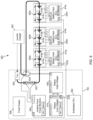
- FIG. 1 B is a diagram illustrating an example power station 102 A for use within microgrid power system 100 , according to an embodiment.
- Power station 102 A includes solar energy source 116 coupled to inverter 118 A and wind energy source 120 coupled to inverter 118 B.
- solar energy source 116 may include a plurality of photovoltaic cells arranged in one or more solar panels.
- Wind energy source 120 may include a plurality of wind turbines or other means for converting kinetic energy into electricity.
- solar energy source 116 , wind energy source 120 , and inverters 118 A and 118 B may constitute an AC power source, such as power source 110 of FIG. 1 A .
- Power generated by solar energy source 116 and wind energy source 120 may be provided to the load centers through a microgrid power distribution network (not shown).
- a power distribution network may include, for example, power lines, and circuit breakers, and may also include step-up and step-down transformers.
- Inverters 118 A and 118 B may be coupled to batteries 126 of battery system 112 via power control system (PCS) 122 A, isolation transformer 124 A, PCS 122 B, and isolation transformer 124 B. In some embodiments, isolation transformers 124 A and 124 B may be omitted. Additionally, in some embodiments, PCS 122 A and PCS 122 B may each constitute a module of a larger power control system. Alternatively, PCS 122 A and PCS 122 B may each include a plurality of power control modules connected in parallel.
- PCS power control system
- PCS 122 A and/or PCS 122 B may be configured to convert AC power provided by solar energy source 116 and wind energy source 120 to DC power in order to charge the plurality of batteries 126 . This charging may be performed during periods when solar energy source 116 and wind energy source 120 are producing excess power, and the state of charge of batteries 126 is low.
- a microgrid controller such as microgrid controller 114 of FIG. 1 A , may determine when to charge batteries 126 based on energy availability.
- PCS 122 A and/or PCS 122 B may also be configured to convert DC power provided by batteries 126 to AC power. This AC power may then be provided to load centers 104 through the microgrid power distribution network to supplement (or in lieu of) power provided by solar energy source 116 and wind energy source 120 .
- Stabilizing battery system 112 may be used to provide this power during periods when solar energy source 116 and wind energy source 120 are producing low energy, such as during the night (for solar energy source 116 ) or periods of low wind (for wind energy source 120 ), to provide a stable supply of AC power to load centers 104 .
- the microgrid controller may determine when to use stabilizing battery system 112 to provide AC power to load centers 104 .
- stabilizing battery system 112 may also be used to control the quality of the power provided by power station 102 A to load centers 104 .
- PCS 122 A and 122 B may include respective power converters, or a single power converter may be employed for both.
- PCS 122 A may be configured to control the quality of the AC power provided by solar energy source 116 and/or wind energy source 120 . This may be accomplished by providing real and/or reactive power from stabilizing battery system 112 to control the voltage and/or frequency of the AC power provided by solar energy source 116 and/or wind energy source 120 to load centers 104 .
- PCS 122 B may be employed to adjust the state of charge of batteries 126 (i.e., charge or discharge batteries 126 ).
- the power converter of PCS 122 A may be configured to operate in voltage control mode, while the power converter of PCS 122 B may be configured to operate in current control mode.
- solar energy source 116 and wind energy source 120 may provide generated current to the microgrid power distribution network via inverters 118 A and 118 B, each operating in current control mode.
- PCS 122 A may then regulate and maintain the voltage of the resulting AC power provided to load centers 104 .
- the operation of PCS 122 A, PCS 122 B, isolation transformer 124 A, and isolation transformer 124 B enables use of batteries 126 to stabilize existing solar, wind, or other energy sources, generally without modification to the operation of these energy sources.
- FIG. 1 C illustrates an example power station 102 B for use within microgrid power system 100 , according to an embodiment.
- Power station 102 B includes the same components as power station 102 A with the exception of wind energy source 120 and inverter 118 B. Thus, the AC power source of power station 102 B is driven only by solar energy source 116 .
- FIG. 1 D illustrates an example power station 102 C for use within microgrid power system 100 , according to an embodiment.
- Power station 102 C includes the same components as power station 102 A with the exception of solar energy source 116 and inverter 118 A. Thus, the AC power source of power station 102 C is driven only by wind energy source 120 .
- FIG. 1 E is a diagram illustrating a load center or local power system 104 for use in microgrid power system 100 , according to an embodiment.
- Local power system 104 includes one or more batteries 136 coupled to a bidirectional power control system (PCS) 134 and a battery management system 138 .
- Battery management system 138 may be similar, for example, to that discussed below.
- Battery management system 138 may be coupled to a local EMS 106 including a controller 140 .
- Local power system 104 also includes switches 132 A-D and a phase sensor 133 . Switches 132 A-D may comprise circuit breakers or any other switching mechanism known in the art. Switches 132 A and 132 B may connect a power grid or off-site power station 102 , as discussed with respect to FIGS.
- Phase sensor 133 is configured to sense the phase of the AC Power being provided by the power grid or off-site power station 102 .
- Meter 130 may be used to monitor the total power usage of local power system 104 (e.g., power used by the building or factory). In an embodiment, the usage monitored by meter 130 may be transmitted to microgrid controller 114 for use by the microgrid controller in determining how to distribute available power within the microgrid power system.
- EMS 106 and controller 140 control the power supplied to loads 142 , 144 , and 146 as well as controlling switches 132 A, 132 C, and 132 D.
- PCS 134 may open switch 132 B to disconnect off-site power.
- PCS 134 may open switch 132 B when the required local power demand exceeds the AC power provided by the off-site power, or at set times (e.g., each night). Switch 132 B may also be operated manually by a user.
- energy management controller 140 may open switch 132 A to disconnect off-site power or may send a command to PCS 134 instructing PCS 134 to open switch 132 B to disconnect off-site power.
- PCS 134 may also provide power to the local loads from batteries 136 .
- the power converter of PCS 134 may be configured to convert DC power supplied by batteries 136 to AC power, which can then be provided to loads 142 , 144 , and 146 .
- the power converter of PCS 134 may be configured to convert AC power provided by the off-site power to DC power to charge batteries 136 .
- a phase sensor 133 may be used to sense and monitor the phase sequence of the AC power provided from the off-site power source.
- phase sensor 133 ensures safe conditions are met prior to closing switch 132 B. For example, when a change is desired to switch from local battery power to off-site AC power, switch 132 A (if present) is closed, and PCS 134 compares the phase of the AC power provided by the off-site power source to the phase of the AC power generated by PCS 134 from power stored in batteries 136 .
- PCS 134 then adjusts the phase of the locally generated AC power, for example, and closes switch 132 B only when the AC power supplied by PCS 134 (from batteries 136 ) is within a predetermined phase angle (e.g., a phase angle that will not cause equipment damage when switch 132 B is closed) of the AC power provided from off-site.
- a predetermined phase angle e.g., a phase angle that will not cause equipment damage when switch 132 B is closed
- Local EMS 106 may include energy management controller 140 to control the power usage of the load center (e.g., the factory or building). In this manner, EMS 106 may ensure that enough energy is available from batteries 136 to power critical loads when off-site power is unavailable (e.g., during the night). In an embodiment, when batteries 136 are being discharged, EMS 106 may adjust loads 142 , 144 , and 146 according to available energy, and control switches 132 C and 132 D to disconnect non-critical loads 144 and 146 to maintain sufficient power for critical loads 142 . For example, critical loads 142 may include power for lights and certain factory machines so that factory workers may continue working during hours of low energy availability. In an embodiment, during periods of excess energy when batteries 136 are being charged, EMS 106 may control PCS 134 to set a charge rate for batteries 136 .
- batteries 136 may be omitted from local power system 104 .
- local power system 104 may remain connected to the power grid or off-site power station at all times, relying on power station 102 to provide all AC power. This option reduces the cost of maintaining a local battery system and may be able to provide sufficient AC power for load centers with smaller power requirements.
- FIG. 1 F is a diagram illustrating an example factory 152 , according to an embodiment.
- Factory 152 may be a load center 104 of microgrid power system 100 , as described in detail with respect to FIGS. 1 A- 1 E .
- Factory 152 includes local battery storage 150 .
- Battery storage 150 may include a plurality of batteries, such as batteries 136 of FIG. 1 E .
- battery storage 150 may be integrated within factory 152 , or directly attached or coupled to factory 152 .
- Battery storage 150 may represent any type of battery electrical storage unit, such as those described herein.
- factory 152 may include solar panels 154 . Power may be provided to factory 152 via a power grid, an off-site power station (e.g., power station 102 of FIG. 1 A ), solar panels 154 , or any combination thereof. In an embodiment, solar panels 154 may be used to supplement the AC power provided to factory 152 from batteries 136 (see FIG. 1 E ) or from the off-site power station. Additionally or alternatively, factory 152 may be part of a co-located load center (e.g., load center 104 ) and power station (e.g., power station 102 ). In this case, solar panels 154 may be part of a power source 110 , as described with respect to FIGS. 1 A- 1 D . In some embodiments, factory 152 does not include solar panels 154 or other power source, and all power is received from a power grid and/or off-site power station.
- factory 152 does not include solar panels 154 or other power source, and all power is received from a power grid and/or off-site
- Factory 152 represents a large-scale factory, for example supporting one thousand to five thousand factory workers 156 .
- the stable power supplied to factory 152 by the energy sources described above provides electricity that enables factory workers 156 to be productive at any time during the day, for example by powering critical lights and machinery.
- FIG. 1 G is a diagram illustrating an example factory 158 , according to an embodiment.
- Factory 158 may be a load center 104 of microgrid power system 100 , as described in detail with respect to FIGS. 1 A- 1 E .
- Factory 158 includes local battery storage 162 .
- Battery storage 162 may include a plurality of batteries, such as batteries 136 of FIG. 1 E .
- battery storage 162 may be integrated within factory 158 , or directly attached or coupled to factory 158 .
- Battery storage 162 may represent any type of battery electrical storage unit, such as those discussed herein.
- factory 158 may include solar panels 160 .
- Power may be provided to factory 158 via a power grid, an off-site power station (e.g., power station 102 of FIG. 1 A ), solar panels 160 , or any combination thereof.
- solar panels 160 may be used to supplement the AC power provided to factory 158 from batteries 136 (see FIG. 1 E ) or from the off-site power station.
- factory 158 may be part of a co-located load center (e.g., load center 104 ) and power station (e.g., power station 102 ).
- solar panels 160 may be part of a power source 110 , as described with respect to FIGS. 1 A- 1 D .
- factory 158 does not include solar panels 160 or other power source, and all power is received from a power grid and/or off-site power station.
- Factory 158 represents a small-scale factory, for example supporting twenty to one hundred factory workers 164 .
- the stable power supplied to factory 158 by the energy sources described above provides electricity that enables factory workers 164 to be productive at any time during the day, for example by powering critical lights and machinery.
- FIG. 1 H is a diagram illustrating an example battery container 168 , according to an embodiment.
- Battery container 168 includes a power converter 172 and a plurality of batteries 170 .
- Power converter may be part of a power control system, such as PCS 122 A or PCS 122 B of FIGS. 1 B- 1 D , or PCS 134 of FIG. 1 E .
- Batteries 170 may represent all or a portion of batteries 126 of FIGS. 1 B- 1 D or local batteries 136 of FIG. 1 E .
- Battery container 168 may be employed in conjunction with various battery storage applications, such as stabilizing battery system 112 of FIGS. 1 A- 1 D and/or batteries 136 of FIG. 1 E .
- battery container 168 may be physically integrated as part of batteries 126 or local batteries 136 within a larger battery storage facility, such as the battery energy storage systems described herein. Battery container 168 may also be implemented as a standalone unit that represents the entirety of batteries 126 or local batteries 136 .
- power converter 172 may convert AC power to DC power to charge batteries 170 , and convert DC power to AC power to provide power to one or more loads, as described with respect to PCS 122 A and 122 B of FIGS. 1 B- 1 D and PCS 134 of FIG. 1 E .
- FIG. 1 I is a diagram illustrating an example state of charge (SoC) 180 of batteries (e.g., batteries 126 ) used in stabilizing battery system 112 of a power station 102 within a microgrid power system 100 over a period of time, for example, one day.
- SoC state of charge
- the state of charge of the battery system may fluctuate throughout the day depending on the energy available from an off-site power source, such as solar energy source 116 or wind energy source 120 .
- Increases in line 180 may represent periods of time in which the battery system is being charged (e.g., in periods of excess power generation), and decreases in line 180 may represent periods of time in which the battery system is being discharged to supplement or maintain the quality of AC power provided by the off-site power source.
- the final decrease in line 180 may represent a nighttime period in which solar power, for example, cannot be provided, and the battery system is being used to supply AC power to one or more load centers.
- the battery may be an electrical energy storage unit (which may also be referred to as a battery energy storage system (“BESS”)) which includes a battery system controller and battery packs.
- BESS battery energy storage system
- Each battery pack has battery cells, a battery pack controller that monitors the cells, a battery pack cell balancer that adjusts the amount of energy stored in the cells, and a battery pack charger.
- the battery pack controller operates the battery pack cell balancer and the battery pack charger to control the state-of-charge of the cells.
- the cells are lithium ion battery cells.
- FIG. 2 A is a diagram that illustrates a networked group of electrical energy storage units 250 that comprise one or more battery packs 258 according to an embodiment.
- the illustrated electrical energy storage units include energy storage unit 252 , energy storage unit 254 , and energy storage unit 256 .
- Energy storage unit 252 includes a large number battery packs such as battery packs 258 a and 258 b .
- Energy storage unit 254 includes a single battery pack 258 c .
- Energy storage unit 256 includes two battery packs 258 d and 258 c .
- the energy storage units can include any number of battery packs 258 .
- the networked battery packs 258 are connected to a data center 262 and can send data to data center 262 using the Internet 261 .
- the data from battery packs 258 can be automatically sent to data center 262 , or the data can be sent to data center 262 in response to signals sent to energy storage units 252 , 254 , and 256 of networked energy storage units 250 by data center 262 .
- the battery data 240 (stored for example in data center 262 ) is analyzed and used to form rate data for insurance purposes.
- the battery data can be analyzed to determine an expected lifetime for particular batteries made by particular battery manufacturers and/or particular battery packs made by particular manufacturers. This expected lifetime data can then be used to determine the cost of insurance sold to cover battery packs 258 . Batteries and battery packs that have a longer expected lifetime can potentially get term insurance coverage at a lower rate than batteries and battery packs that have a shorter expected lifetime.
- the rate data is determined similarly to how life insurance rate data is determined.
- Battery lifetime monitor 270 tracks the lifetime usage of the battery. In an embodiment, this is done by calculating a battery lifetime value as described in more detail below with reference to FIG. 36 A .
- This value may be a product of three factors multiplied together and then continually accumulated. These three factors are a current factor, a voltage factor, and a temperature factor, which are further described below with reference to FIGS. 33 , 34 , and 35 .
- the battery lifetime value increases at a greater rate than when the battery is used at lower charge or discharge rates.
- the battery lifetime value does not increase.
- the rate at which the battery lifetime value increases is also affected by the voltage factor and the temperature factor.
- Battery maintenance manager 264 reports issues with the battery pack so that they may be corrected by maintenance.
- Battery balancing manager 265 balances the battery in a reliable and cost effective manner. This is described in more detail below.
- Battery calibration manager 266 recalibrates battery pack values such as state-of-charge, amp-hour capacity, Watt-hour capacity, voltage measurement calibration factors and temperature calibration factors.
- Battery configuration manager 267 implements among other things the plug and play features of the battery pack. These include such things as establishing communication with other components of an energy storage unit when the battery pack is first installed and energized, obtaining a communication address of ID, and associating itself with a particular network of battery packs to form an energy storage unit.
- Battery communication manager 268 monitors communications between the battery pack and other system components to ensure the safe and reliable operation of the battery pack. It also tries to reestablish communications if communications are lost.
- Battery software update manager 269 enables and facilitates the remote updating of the battery pack software and firmware. This updating can be done automatically when the update feature is enabled.
- FIG. 2 D is a diagram that illustrates an electrical energy storage unit 252 according to an embodiment of the disclosure.
- electrical energy storage unit 252 includes battery units 258 a and 258 b , control units 259 a and 259 b , and inverters 260 a and 260 b .
- electrical energy storage unit 252 is housed in a container 251 , which is similar to a shipping container. In such embodiments, electrical energy storage unit 252 is movable and can be transported by truck.
- electrical energy storage unit 252 is suitable for storing large amounts of electrical energy.
- FIG. 2 E is a diagram that illustrates the electrical energy storage unit 252 of FIG. 2 D being used as a part of a renewable wind energy system 200 .
- Wind energy system 200 includes wind turbines 202 a and 202 b .
- Energy from wind turbine 202 a is stored in an electrical energy storage unit 252 a .
- Energy from wind turbine 202 b is stored in an electrical energy storage unit 252 b .
- electrical energy storage units 252 a and 252 b enable stored electrical energy generated by wind turbines 202 a and 202 b to be dispatched.
- FIG. 2 F is a diagram that illustrates the electrical energy storage unit 252 of FIG. 2 D being used as a part of a renewable solar energy system 220 .
- Solar energy system 220 includes a solar array 222 and an electrical energy storage unit 252 . Energy from solar array 222 is stored in the electrical energy storage unit 252 . Electrical energy storage unit 252 enables stored electrical energy generated by solar array 222 to be dispatched.
- FIG. 2 G is a diagram that illustrates the electrical energy storage unit 252 of FIG. 2 D being used as a part of a grid energy system 230 .
- Grid energy system 230 includes electrical equipment 232 and an electrical energy storage unit 252 . Energy from grid energy system 230 is stored in the electrical energy storage unit 252 . Electrical energy stored by electrical energy storage unit 252 can be dispatched.
- FIG. 3 is a diagram that further illustrates battery units 304 a and 304 b of electrical energy storage unit 252 .
- battery units 304 a and 304 b are formed using multiple battery packs 302 according to an embodiment of the disclosure.
- three battery packs 302 a - c are shown.
- Battery packs 302 a and 302 c form a part of battery unit 304 a .
- Battery pack 302 b forms a part of battery unit 304 b.
- FIG. 4 is a diagram that further illustrates a battery pack 302 according to an embodiment of the disclosure.
- Battery pack 302 includes an enclosure 402 , a lid 404 , a power connector 406 , and two signal connectors 408 a and 408 b .
- Enclosure 402 and lid 404 are preferably made from a strong plastic or metal.
- the power connector 406 includes connections for the positive and negative terminals of the battery pack, connections for the DC supply power, and connections for AC supply power. In embodiments of the disclosure, only DC supply power or AC supply power can be used.
- the signal connectors 408 a and 408 b are RJ-45 connectors, but other types of connectors can be used too.
- the signal connectors are used, for example, for CAN (CANBus) communications between battery pack 302 and other components of electrical energy storage unit 252 .
- CAN CAN Buss
- enclosure 402 houses a battery lift plate 410 that supports two battery modules 412 a and 412 b .
- Battery modules 412 a and 412 b each include multiple pouch-type batteries connected together in a series/parallel configuration.
- battery modules 412 a and 412 b can comprise, but are not limited to, for example, 10 to 50 AH cells arranged in a 1P16S configuration, a 2P16S configuration, a 3P16S configuration, or a 4P16S configuration. Other configurations are also possible and form a part of the scope of the disclosure.
- the battery cells are connected using a printed circuit board that includes the wiring and connections for voltage and temperature monitoring of the battery cells as well as for balancing the battery cells.
- enclosure 402 Other items housed in enclosure 402 include a battery pack controller 414 , an AC power supply 416 , a DC power supply 418 , a battery pack cell balancer 420 , and a fuse and fuse holder 422 . In embodiments of the disclosure, only AC power supply 416 or DC power supply 418 can be used.
- FIG. 5 is a diagram that further illustrates battery pack controller 414 according to an embodiment of the disclosure.
- battery pack controller 414 includes a battery/DC input 502 , a charger switching circuit 504 , a DIP-switch 506 , a JTAG connection 508 .
- RS-232 connection 510 fan connectors 512 , a CAN (CANBus) connection 514 , a microprocessor unit (MCU) 516 , memory 518 , a balancing board connector 520 , a battery box (enclosure) temperature monitoring circuit 522 , a battery cell temperature measurement circuit 524 , a battery cell voltage measurement circuit 528 , a DC-DC power supply 530 , a watchdog timer 532 , and a reset button 534 .
- the battery cell temperature measurement circuit 524 and the battery cell voltage measurement circuit 528 are coupled to MCU 516 using multiplexers (MUX) 526 a and 526 b , respectively.
- MUX multiplexers
- battery pack controller 414 is powered from energy stored in the battery cells. Battery pack controller 414 is connected to the battery cells by battery/DC input 502 . In other embodiments, battery pack controller 414 is powered from a DC power supply connected to battery/DC input 502 . DC-DC power supply 530 then converts the input DC power to one or more power levels appropriate for operating the various electrical components of battery pack controller 414 .
- Charger switching circuit 504 is coupled to MCU 516 .
- Charger switching circuit 504 and MCU 516 are used to control operation of AC power supply 416 and/or DC power supply 418 .
- AC power supply 416 and/or DC power supply 418 are used to add energy to the battery cells of battery pack 302 .
- Battery pack controller 414 includes several interfaces and connectors for communicating. These interfaces and connectors are coupled to MCU 516 as shown in FIG. 5 .
- these interfaces and connectors include: DIP-switch 506 , which is used to set a portion of software bits used to identify battery pack controller 414 ; JTAG connection 508 , which is used for testing and debugging battery pack controller 414 ; RS-232 connection 510 , which is used to communicate with MCU 516 ; CAN (CANBus) connection 514 , which is used to communicate with MCU 516 ; and balancing board connector 520 , which is used to communicate signals between battery pack controller 414 and battery pack cell balancer 420 .
- DIP-switch 506 which is used to set a portion of software bits used to identify battery pack controller 414
- JTAG connection 508 which is used for testing and debugging battery pack controller 414
- RS-232 connection 510 which is used to communicate with MCU 516
- Fan connectors 512 are coupled to MCU 516 . Fan connectors 512 are used together with MCU 516 and battery box temperature monitoring circuit 522 to operate one or more optional fans that can aid in cooling battery pack 302 .
- battery box temperature monitoring circuit 522 includes multiple temperature sensors that can monitor the temperature of battery pack cell balancer 420 and/or other heat sources within battery pack 302 such as, for example, AC power supply 416 and/or DC power supply 418 .
- Microprocessor unit (MCU) 516 is coupled to memory 518 .
- MCU 516 is used to execute an application program that manages battery pack 302 .
- the application program performs the following functions: monitors the voltage and temperature of the battery cells of battery pack 302 , balances the battery cells of battery pack 302 , monitor and controls (if needed) the temperature of battery pack 302 , handles communications between battery pack 302 and other components of electrical energy storage system 252 , and generates warnings and/or alarms, as well as taking other appropriate actions, to prevent over-charging or over-discharging the battery cells of battery pack 302 .
- Battery cell temperature measurement circuit 524 is used to monitor the cell temperatures of the battery cells of battery pack 302 .
- individual temperature monitoring channels are coupled to MCU 516 using a multiplexer (MUX) 526 a .
- MUX multiplexer
- the temperature readings are used to ensure that the battery cells are operated within their specified temperature limits and to adjust temperature related values calculated and/or used by the application program executing on MCU 516 , such as, for example, how much dischargeable energy is stored in the battery cells of battery pack 302 .
- Battery cell voltage measurement circuit 528 is used to monitor the cell voltages of the battery cells of battery pack 302 .
- individual voltage monitoring channels are coupled to MCU 516 using a multiplexer (MUX) 526 b .
- the voltage readings are used, for example, to ensure that the battery cells are operated within their specified voltage limits and to calculate DC power levels.
- Watchdog timer 532 is used to monitor and ensure the proper operation of battery pack controller 414 . In the event that an unrecoverable error or unintended infinite software loop should occur during operation of battery pack controller 414 , watchdog timer 532 can reset battery pack controller 414 so that is resumes operating normally.
- Reset button 534 is used to manually reset operation of battery pack controller 414 . As shown in FIG. 5 , reset button 534 is coupled to MCU 516 .
- FIG. 6 A is a diagram that illustrates a battery pack cell balancer 420 a according to an embodiment of the disclosure.
- Battery pack cell balancer 420 a includes a first set of resistors 604 a - d coupled through switches 606 a - d to a battery cells connector 602 a and a second set of resistors 604 e - h coupled through switches 606 e - h to a battery cells connector 602 b .
- Battery cells connectors 602 a and 602 b are used to connect battery pack cell balancer 420 a to the battery cells of battery pack 302 .
- a battery pack electronic control unit (ECU) connector 608 connects switches 604 a - h to battery pack controller 414 .
- ECU electronice control unit
- switches 604 a - h of battery pack cell balancer 420 a are selectively opened and closed to vary the amount of energy stored in the battery cells of battery pack 302 .
- the selective opening and closing of switches 604 a - h allows energy stored in particular battery cells of battery pack to be discharged through resistors 604 a - h , or for energy to bypass selected battery cells during charging of the battery cells of battery pack 302 .
- the resistors 604 a - h are sized to permit a selected amount of energy to be discharged from the battery cells of battery pack 302 in a selected amount of time and to permit a selected amount of energy to bypass the battery cells of battery pack 302 during charging. In an embodiment, when the charging energy exceeds the selected bypass energy amount, the closing of switches 604 a - h is prohibited by battery pack controller 414 .
- FIG. 6 B is a diagram that illustrates a battery pack cell balancer 420 b .
- Battery pack cell balancer 420 b includes a first capacitor 624 a coupled to two multiplexers (MUX) 620 a and 620 b through switches 622 a and 622 b , and a second capacitor 624 b coupled to two multiplexers (MUX) 620 c and 620 d through switches 622 c and 622 d .
- Multiplexers 620 a and 620 b are connected to battery cells connector 602 a .
- Multiplexers 620 c and 620 d are connected to battery cells connector 602 b .
- Battery pack electronic control unit (ECU) connector 608 connects switches 622 a - d to battery pack controller 414 .
- ECU battery pack electronic control unit
- multiplexers 620 a - b and switches 622 a - b are first configured to connect capacitor 624 a to a first battery cell of battery pack 302 . Once connected, capacitor 624 a is charged by the first battery cell, and this charging of capacitor 624 a reduces the amount of energy stored in the first battery cell. After charging, multiplexers 620 a - b and switches 622 a - b are then configured to connect capacitor 624 a to a second battery cell of battery pack 302 . This time, energy stored in capacitor 624 a is discharged into the second battery cell thereby increasing the amount of energy stored in the second battery cell.
- capacitor 624 a shuttles energy between various cells of battery pack 302 and thereby balances the battery cells.
- multiplexers 620 c - d , switches 622 c - d , and capacitor 624 b are also used to shuttle energy between various cells of battery pack 302 and balance the battery cells.
- FIG. 6 C is a diagram that illustrates a battery pack cell balancer 420 c .
- Battery pack cell balancer 420 c includes a first inductor 630 a coupled to two multiplexers (MUX) 620 a and 620 b through switches 622 a and 622 b , and a second inductor 630 b coupled to two multiplexers (MUX) 620 c and 620 d through switches 622 c and 622 d .
- Multiplexers 620 a and 620 b are connected to battery cells connector 602 a .
- Multiplexers 620 c and 620 d are connected to battery cells connector 602 b .
- Battery cells connectors 602 a and 602 b are used to connect battery pack cell balancer 420 a to the battery cells of battery pack 302 .
- Inductor 630 a is also connected by a switch 632 a to battery cells of battery pack 302
- inductor 630 b is connected by a switch 632 b to battery cells of battery pack 302 .
- Battery pack electronic control unit (ECU) connector 608 connects switches 622 a - d and switches 632 a - b to battery pack controller 414 .
- switch 632 a is first closed to allow energy from the batteries of battery pack 302 to charge inductor 630 a .
- This charging removes energy from the battery cells of battery pack 302 and stores the energy in inductor 630 a .
- multiplexers 620 a - b and switches 622 a - b are configured to connect inductor 630 a to a selected battery cell of battery pack 302 . Once connected, inductor 630 a discharges its stored energy into the selected battery cell thereby increasing the amount of energy stored in the selected battery cell.
- inductor 630 a is thus used to take energy from the battery cells of battery pack 302 connected to inductor 632 a by switch 632 a and to transfer this energy only to selected battery cells of battery pack 302 .
- the process thus can be used to balance the battery cells of battery pack 302 .
- multiplexers 620 c - d , switches 622 c - d and 632 b , and inductor 630 b are also used to transfer energy and balance the battery cells of battery pack 302 .
- each of the circuits described in FIGS. 6 A-C have advantages in their operation, and in embodiments of the disclosure elements of these circuits are combined and used together to bypass and/or transfer energy and thereby balance the battery cells of battery pack 302 .
- FIG. 7 is a diagram that further illustrates an electrical energy storage unit 252 according to an embodiment of the disclosure.
- a control unit 259 includes multiple battery system controllers 702 a - c .
- each battery system controller 702 monitors and controls a subset of the battery packs 302 that make up a battery unit 304 (see FIG. 3 ).
- the battery system controllers 702 are linked together using CAN (CANBus) communications, which enables the battery system controllers 702 to operate together as part of an overall network of battery system controllers.
- This network of battery system controllers can manage and operate any size battery system such as, for example, a multi-megawatt-hour centralized storage battery system.
- one of the networked battery system controllers 702 can be designated as a master battery system controller and used to control battery charge and discharge operations by sending commands that operate one or more inverters and/or chargers connected to the battery system.
- electrical energy storage unit 252 includes a bi-directional inverter 260 .
- Bi-directional inverter 260 is capable of both charging a battery unit 304 and discharging the battery unit 304 using commands issued, for example, via a computer over a network (e.g. the Internet, an Ethernet, et cetera) as described in more detail below with reference to FIGS. 10 B and 10 C .
- a network e.g. the Internet, an Ethernet, et cetera
- both the real power and the reactive power of inverter 260 can be controlled.
- inverter 260 can be operated as a backup power source when grid power is not available and/or electrical energy storage unit 252 is disconnected from the grid.
- embedded CPU 802 monitors and maintains common electrical system information such as inverter output power, inverter output current, inverter AC voltage, inverter AC frequency, charger output power, charger output current, charger DC voltage, et cetera. Additional status and control information monitored and maintained by embodiments of embedded CPU 802 will also be apparent to persons skilled in the relevant arts given the description herein.
- battery system controller 702 includes an enclosure 840 that houses embedded CPU 802 , ampere-hour/power monitor 806 , low voltage relay controller 816 , high voltage relay controller 826 , a fuse holder and fuse 830 , current shunt 832 , contactor 834 , and power supply 836 .
- each power connect 856 has two larger current carrying connection pins and four smaller current carrying connection pins.
- One of the power connectors 856 is used to connect one end of current shunt 832 and one end of contactor 834 to the power wires connecting together battery packs 302 (e.g., using the two larger current carrying connection pins) and for connecting the input power to one or both of power supplies 416 or 418 of battery packs 302 to control a relay or relays inside enclosure 840 (e.g., using either two or four of the four smaller current carrying connection pins).
- the purpose of high voltage relays 856 a and 856 b is to make or to break a power carrying conductor of a charger and/or an inverter connected to battery packs 302 .
- these relays can be used to prevent operation of the charger and/or inverter and thus protect against the over-charging or over-discharging of battery packs 302 .
- FIG. 9 is a diagram that illustrates an electrical energy storage unit 900 according to an embodiment of the disclosure.
- Electrical energy storage unit 900 as described herein, can be operated as a stand-alone electrical energy storage unit, or it can be combined together with other electrical energy storage units 900 to form a part of a larger electrical energy storage unit such as, for example, electrical energy storage unit 252 .
- electrical energy storage unit 900 includes a battery system controller 702 coupled to one or more battery packs 302 a - n .
- battery system controller 702 can also be coupled to one or more chargers and one or more inverters represented in FIG. 9 by inverter/charge 902 .
- electrical energy storage unit 900 performs as follows.
- Embedded CPU 802 continually monitors status information transmitted by the various components of electrical energy storage unit 900 . If based on this monitoring, embedded CPU 802 determines that the unit is operating properly, then when commanded, for example, by an authorized user or by a program execution on embedded CPU 802 (see, e.g., FIG. 10 B below), embedded CPU 802 sends a command to low voltage relay controller 816 to close a MOSFET switch associated with contactor 834 . Closing this MOSFET switch activates a relay on high voltage relay controller 826 , which in turn closes contactor 834 . The closing of contactor 834 couples the charger (i.e., inverter/charger 902 ) to battery packs 302 a - n.
- charger i.e., inverter/charger 902
- embedded CPU 802 sends a command to the charger to start charging the battery packs.
- this command can be, for example, a charger output current command or a charger output power command.
- the charge will start charging.
- This charging causes current to flow through current shunt 832 , which is measured by ampere-hour/power monitor 806 .
- Ampere-hour/power monitor 806 also measures the total voltage of the battery packs 302 a - n . In addition to measuring current and voltage, ampere-hour/power monitor 806 calculates a DC power value, an ampere-hour value, and a watt-hour value.
- the ampere-hour value and the watt-hour value are used to update an ampere-hour counter and a watt-hour counter maintained by ampere-hour/power monitor 806 .
- the current value, the voltage value, the ampere-hour counter value, and the watt-hour counter value are continuously transmitted by ampere-hour/power monitor 806 to embedded CPU 802 and the battery packs 302 a - n.
- battery packs 302 a - n continuously monitor the transmissions from ampere-hour/power monitor 806 and use the ampere-hour counter values and watt-hour counter values to update values maintained by the battery packs 302 a - n .
- These values include battery pack and cell state-of-charge (SOC) values, battery pack and cell ampere-hour (AH) dischargeable values, and battery pack and cell watt-hour (WH) dischargeable values, as described in more detail below with reference to FIG. 21 .
- embedded CPU 802 continuously monitors the transmissions from ampere-hour/power monitor 806 as well as the transmissions from battery packs 302 a - n , and uses the ampere-hour counter transmitted values and the battery pack 302 a - n transmitted values to update values maintained by embedded CPU 802 .
- the values maintained by embedded CPU 802 include battery pack and cell SOC values, battery pack and cell AH dischargeable values, battery pack and cell WH dischargeable values, battery and cell voltages, and battery and cell temperatures as described in more detail below with reference to FIGS. 22 A and 22 B .
- the stop criteria include, for example, a maximum SOC value, a maximum voltage value, or a stop-time value.
- embedded CPU 802 sends a command to the charger to stop the charging. Once the charging is stopped, embedded CPU 802 sends a command to low voltage relay controller 816 to open the MOSFET switch associated with contactor 834 . Opening this MOSFET switch changes the state of the relay on high voltage relay controller 826 associated with contactor 834 , which in turn opens contactor 834 . The opening of contactor 834 decouples the charger (i.e., inverter/charger 902 ) from battery packs 302 a - n.
- the charger i.e., inverter/charger 902
- battery packs 302 a - n are responsible for maintaining the proper SOC and voltage balances of their respective battery modules 412 .
- proper SOC and voltage balances are achieved by the battery packs using their battery pack controllers 414 , and/or their AC power supplies 416 to get their battery modules 412 to conform to target values such as, for example, target SOC values and target voltage values transmitted by embedded CPU 802 .
- This balancing can take place either during a portion of the charging evolution, after the charging evolution, or at both times.
- a discharge evolution by electrical energy storage unit 900 occurs in a manner similar to that of a charge evolution except that the battery packs 302 a - n are discharged rather than charged.
- FIG. 10 A is a diagram that further illustrates electrical energy storage unit 252 according to an embodiment of the disclosure.
- electrical energy storage unit 252 is formed by combining and networking several electrical energy storage units 900 a - n .
- Electrical energy storage unit 900 a includes a battery system controller 702 a and battery packs 302 a 1 -n 1 .
- Electrical energy storage unit 900 n includes a battery system controller 702 n and battery packs 302 a n - n n .
- the embedded CPUs 802 a - n of the battery system controllers 702 a - n are coupled together and communicate with each other using CAN (CANBus) communications. Other communication protocols can also be used.
- Information communicated between the embedded CPUs 802 a - n include information identified below with reference to FIGS. 22 A and 22 B .
- electrical energy storage unit 252 operates similarly to that described herein for electrical energy storage system 900 .
- Each battery system controller 702 monitors and controls its own components such as, for example, battery packs 302 .
- one of the battery system controllers 702 operates as a master battery system controller and coordinates the activities of the other battery system controllers 702 .
- This coordination includes, for example, acting as an overall monitor for electrical energy storage unit 252 and determining and communicating target values such as, for example target SOC values and target voltage values that can be used to achieve proper battery pack balancing. More details regarding how this is achieved are described below, for example, with reference to FIG. 25 .
- FIG. 10 B is a diagram that illustrates an electrical energy storage system 1050 according to an embodiment of the disclosure.
- system 1050 includes an electrical energy storage unit 252 that is in communication with a server 1056 .
- Server 1056 is in communication with data bases/storage devices 1058 a - n .
- Server 1056 is protected by a firewall 1054 and is shown communicating with electrical energy storage unit 252 via internet network 1052 .
- other means of communication are used such as, for example, cellular communications or an advanced metering infrastructure communication network.
- Users of electrical energy storage system 1050 such as, for example, electric utilities and/or renewable energy asset operators interact with electrical energy storage system 1050 using user interface(s) 1060 .
- the user interfaces are graphical, web-based user interfaces, for example, which can be accessed by computers connected directly to server 1056 or to internet network 1052 .
- the information displayed and/or controlled by user interface(s) 1060 include, for example, the information identified below with references to FIGS. 19 A-E , 21 , 22 A-B, and 23 A-B. Additional information as will be apparent to persons skilled in the relevant art(s) given the description herein can also be included and/or controlled.
- user interface(s) 1060 can be used to update and/or change programs and control parameters used by electrical energy storage unit 252 .
- a user can control electrical energy storage unit 252 in any desired manner. This includes, for example, controlling when, how much, and at what rate energy is stored by electrical energy storage unit 252 and when, how much, and at what rate energy is discharged by electrical energy storage unit 252 .
- the user interfaces can operate one or more electrical energy storage units 252 so that they respond, for example, like spinning reserve and potentially prevent a power brown out or black out.
- electrical energy storage system 1050 is used to learn more about the behavior of battery cells.
- Server 1056 can be used for collecting and processing a considerable amount of information about the behavior of the battery cells that make up electrical energy storage unit 252 and about electrical energy storage unit 252 itself.
- information collected about the battery cells and operation of electrical energy storage unit 252 can be utilized by a manufacturer, for example, for improving future batteries and for developing a more effective future system. The information can also be analyzed to determine, for example, how operating the battery cells in a particular manner effects the battery cells and the service life of the electrical energy storage unit 252 . Further features and benefits of electrical energy storage system 1050 will be apparent to persons skilled in the relevant art(s) given the description herein.
- FIG. 10 C is a diagram that illustrates an electrical energy storage system 1050 according to an alternative embodiment of the disclosure.
- a user of the electrical energy storage system 1050 may use a computer 1070 (on which a user interface may be provided) to access the electrical energy storage unit 252 via a network connection 1080 other than the internet.
- the network 1080 in FIG. 10 C may be any network contemplated in the art, including an Ethernet, or even a single cable that directly connects the computer 1070 to the electrical energy storage unit 252 .
- FIGS. 11 - 20 are diagrams that further illustrate exemplary electrical energy storage units and various electrical energy storage systems that employee the electrical energy storage units according to the disclosure.
- FIG. 11 is a diagram that illustrates an electrical energy storage system 1100 according to an embodiment of the disclosure.
- Electrical energy storage system 1100 includes an electrical energy storage unit 900 , a generator 1104 , cellular telephone station equipment 1112 , and a cellular telephone tower and equipment 1114 .
- electrical energy storage unit 900 includes a battery 1102 comprised on ten battery packs 302 a - j , a battery system controller 702 , a charger 1106 , and an inverter 1108 .
- battery 1102 can contain more ten or less than ten battery packs 302 .
- generator 1104 is run and used to charge battery 1102 via charger 1106 .
- generator 1104 is shutdown. Battery 1102 is then ready to supply power to cellular telephone station equipment 1112 and/or to equipment on the cellular telephone tower.
- Battery system controller 702 monitors and controls electrical energy storage unit 900 as described herein.
- inverter 1108 can operate at the same time charger 1106 is operating so that inverter 1108 can power equipment without interruption during charging of battery 1102 .
- Electrical energy storage system 1100 can be use for backup power (e.g., when grid power is unavailable), or it can be used continuously in situations in which there is no grid power present (e.g., in an off-grid environment).
- FIG. 12 is a diagram that illustrates an electrical energy storage system 1200 according to an embodiment of the disclosure.
- Electrical energy storage system 1200 is similar to electrical energy storage system 1100 except that electrical energy storage unit 900 now powers a load 1202 .
- Load 1202 can be any electrical load so long as battery 1102 and generator 1104 are sized accordingly.
- Electrical energy storage system 1200 is useful, for example, in off-grid environments such as remote hospitals, remote schools, remote government facilities, et cetera. Because generator 1104 is not required to run continuously to power load 1202 , significant fuel savings can be achieved as well as an improvement in the operating life of generator 1104 . Other savings can also be realized using electrical energy storage system 1200 such as, for example, a reduction in the costs of transporting the fuel needed to operate generator 1104 .
- FIG. 13 is a diagram that illustrates an electrical energy storage system 1300 according to an embodiment of the disclosure.
- Electrical energy storage system 1300 is similar to electrical energy storage system 1200 except that generator 1104 has been replaced by solar panels 1302 .
- solar panels 1302 are used to generate the electricity that is used to charge battery 1102 and to power load 1202 .
- Electrical energy storage system 1300 is useful, for example, in off-grid environments similar to electrical energy storage system 1200 .
- One advantage of electrical energy storage system 1300 over electrical energy storage system 1200 is that no fuel is required. Not having a generator and the no fuel requirement makes electrical energy storage system 1300 easier to operate and maintain than electrical energy storage system 1200 .
- FIG. 14 is a diagram that illustrates an electrical energy storage system 1400 according to an embodiment of the disclosure.
- Electrical energy storage system 1400 is similar to electrical energy storage system 1300 except that solar panels 1302 have been replaced by a grid connection 1402 .
- grid connection 1402 is used to provide the electricity that is used to charge battery 1102 and to power load 1202 .
- Electrical energy storage system 1400 is useful, for example, in environments where grid power is available.
- One advantage of electrical energy storage system 1400 over electrical energy storage system 1300 is that its initial purchase price is less than the purchase price of electrical energy storage system 1400 . This is because no solar panels 1302 are required.
- embedded CPU 802 works together with battery packs 302 a - 302 n and ampere-hour/power monitor 806 to manage battery 1102 .
- the software resident and executing on embedded CPU 802 , the battery pack controller 414 a - n of battery packs 302 a - n , and ampere-hour/power monitor 806 ensure safe operation of battery 1102 at all times and take appropriate action, if necessary, to ensure for example that battery 1102 is neither over-charged nor over-discharged.
- ampere-hour/power monitor 806 includes a memory 810 that stores an application program 2010 .
- This application program is executed using MCU 808 .
- application program 2010 is responsible for keeping track of how much charge is put into battery 1102 during battery charging evolutions or taken out of battery 1102 during battery discharging evolutions. This information is communicated to embedded CPU 802 and the battery system controllers 414 of battery packs 302 .
- embedded CPU 802 determines that battery pack controller 414 is operating with the correct hardware and software, embedded CPU 802 verifies that battery pack 414 is operating with the correct configuration data. If the configuration data is not correct, embedded CPU 802 provides the correct configuration data to battery pack controller 414 , and battery pack controller 414 saves this data for use during its next boot up. Once embedded CPU 802 verifies that battery pack controller 414 is operating with the correct configuration data, battery pack controller 414 executes its application software until it shuts down.
- the application software includes a main program that runs several procedures in a continuous while loop.
- FIG. 21 is a diagram that illustrates exemplary data obtained and/or maintained by the battery pack controllers 414 of battery packs 302 .
- this data includes: the SOC of the battery pack as well as the SOC of each cell; the voltage of the battery pack as well as the voltage of each cell; the average temperature of the battery pack as well as the temperature of each cell; the AH dischargeable of the battery pack as well as each cell; the WH dischargeable of the battery pack as well as each cell; the capacity of the battery pack as well as each cell; information about the last calibration discharge of the battery pack; information about the last calibration charge of the battery pack, information about the AH and WI-I efficiency of the battery pack and each cell; and self discharge information.
- FIGS. 22 A and 23 B are diagrams that illustrate exemplary data obtained and/or maintained by embedded CPU 802 in an embodiment of electrical energy storage unit 900 according to the disclosure.
- this data includes: SOC information about battery 1102 and each battery pack 302 ; voltage information about battery 1102 and each battery pack 302 ; temperature information about battery 1102 and each battery pack 302 ; AH dischargeable information about battery 1102 and each battery pack 302 ; WH dischargeable information about battery 1102 and each battery pack 302 ; capacity information about battery 1102 and each battery pack 302 ; information about the last calibration discharge of battery 1102 and each battery pack 302 ; information about the last calibration charge of battery 1102 and each battery pack 302 , information about the AH and WH efficiency of battery 1102 and each battery pack 302 ; and self discharge information.
- embedded CPU 802 In addition to the data identified in FIGS. 22 A and 23 B , embedded CPU 802 also obtains and maintains data related to the health or cycle life of battery 1102 . This data is identified in FIGS. 23 A and 23 B .
- the data shown in FIGS. 23 A and 23 B represents a number of charge and discharge counts (i.e., counter values), which work as follows. Assume for example that the battery is initially at 90% capacity, and it is discharged down to 10% of its capacity. This discharge represents an 80% capacity discharge, in which the ending discharge state is 10% of capacity. Thus, for this discharge, the discharge counter represented by a battery SOC after discharge of 10-24%, and which resulted from a 76-90% battery capacity discharge (i.e., the counter in FIG. 23 B having a value of 75), would be incremented. In a similar manner, after each charge evolution or discharge evolution of the battery, embedded CPU 802 determines the appropriate counter to increment and increments it.
- counter values i.e., counter values
- a procedure implemented in software adds the values of the counts, using different weights for different counter values, to determine an effective cycle-life for the battery.
- the exemplary counters identified in FIGS. 23 A and 23 B are intended to be illustrative and not limiting.
- FIGS. 24 A-B are diagrams that illustrate how calibration, charging and discharging evolutions of an electrical energy storage unit are controlled according to an embodiment of the disclosure.
- the battery of an electrical energy storage unit is managed based on both battery cell voltage levels and battery cell state-of-charge (SOC) levels.
- four high voltage values 2402 i.e., V H1 , V H2 , V H3 , and V H4
- four high state-of-charge values 2406 i.e., SOC H1 , SOC H2 , SOC H3 , and SOC H4
- four low voltage values 2404 i.e., V L1 , V L2 , V L3 , and V L4
- four low state-of-charge values 2408 i.e., SOC L1 , SOC L2 , SOC L3 , and SOC L4
- SOC L1 , SOC L2 , SOC L3 , and SOC L4 are used to control discharging evolution.
- the voltages 2410 a for a particular set of battery cells can all be below a value of V H1 , while the SOC values 2410 b for some or all of these cells is at or above a value of SOC H1 .
- the voltages 2410 c for a set of battery cells can all be above a value of V L1 while the SOC values 2410 d for some or all of these cells is at or below a value of SOC L1 . Therefore, as described in more detail below, all eight voltage values and all eight SOC values are useful, as described herein, for managing the battery of an electrical energy storage unit according to the disclosure.
- cell voltage values and cell SOC values are important to the proper operation of an electrical energy storage unit according to the disclosure, it is necessary to periodically calibrate the unit so that it is properly determining the voltage levels and the SOC levels of the battery cells. This is done using a calibration procedure implemented in software.
- the calibration procedure is initially executed when a new electrical energy storage unit is first put into service. Ideally, all the cells of the electrical energy storage unit battery should be at about the same SOC (e.g., 50%) when the battery cells are first installed in the electrical energy storage unit. This requirement is to minimize the amount of time needed to complete the initial calibration procedure.
- the calibration procedure is executed whenever one of the following recalibration triggering criteria is satisfied: Criteria 1: a programmable recalibration time interval such as, for example six months have elapsed since the last calibration date; Criteria 2: the battery cells have been charged and discharged (i.e., cycled) a programmable number of weighted charge and discharge cycles such as, for example, the weighted equivalent of 280 full charge and full discharge cycles; Criteria 3: the high SOC cell and the low SOC cell of the electrical energy storage unit battery differ by more than a programmable SOC percentage such as, for example 2-5% after attempting to balance the battery cells; Criteria 4: during battery charging, a situation is detected where one cell reaches a value of V H4 while one or more cells are at a voltage of less than V H1 (see FIG.
- Criteria 5 during battery discharging, a situation is detected where one cell reaches V L4 while one or more cells are at a voltage of greater than V L1 , and this situation cannot be corrected by cell balancing.
- a battery recalibration flag is set by embedded CPU 802 .
- the first battery charge performed after the battery recalibration flag is set is a charge evolution that fully charges all the cells of the battery.
- the purpose of this charge is to put all the cells of the battery into a known full charge state. After the battery cells are in this known full charge state, the immediately following battery discharge is called a calibration discharge.
- the purpose of the calibration discharge is to determine how many dischargeable ampere-hours of charge are stored in each cell of the battery and how much dischargeable energy is stored in each cell of the battery when fully charged.
- the battery charge conducted after the calibration discharge is called a calibration charge.
- the first charge after the battery recalibration flag is set is performed as follows.
- Step 1 Charge the cells of the battery at a constant current rate of CAL-I until the first cell of the battery reaches a voltage of V H2 .
- Step 2 Once the first cell of the battery reaches a voltage of V H2 , reduce the battery cell charging current to a value called END-CHG-I, and resume charging the battery cells.
- Step 3 Continue charging the battery cells at the END-CHG-I current until all cells of the battery have obtained a voltage value between V H3 and V H4 .
- Step 4 If during Step 3, any cell reaches a voltage of V H4 : (a) Stop charging the cells; (b) Discharge, for example, using balancing resistors all battery cells having a voltage greater than V H3 until these cells have a voltage of V H3 ; (c) Once all cell voltages are at or below V H3 , start charging the battery cells again at the END-CHG-I current; and (d) Loop back to Step 3.
- SOC H3 e.g., an SOC of about 98%).
- the charge rate (CAL-I) should be about 0.3 C and the END-CHG-I current should be about 0.02 to 0.05 C.
- the first discharge following the above charge is a calibration discharge.
- the calibration discharge is performed as follows. Step 1: Discharge the cells of the battery at a constant current rate of CAL-I until the first cell of the battery reaches a voltage of V L2 . Step 2: Once the first cell of the battery reaches a voltage of V L2 , reduce the battery cell discharging current to a value called END-DISCHG-I (e.g., about 0.02-0.05 C), and resume discharging the battery cells. Step 3: Continue discharging the battery cells at the END-DISCHG-I current until all cells of the battery have obtained a voltage value between V L3 and V L4 .
- END-DISCHG-I e.g., about 0.02-0.05 C
- Step 4 If during Step 3, any cell reaches a voltage of V L4 : (a) Stop discharging the cells; and (b) Discharge, for example using the balancing resistors all battery cells having a voltage greater than V L3 until these cells have a voltage of V L3 .
- the ampere-hours discharged by each cell and the watt-hours discharged by each cell determine the ampere-hours discharged by each cell and the watt-hours discharged by each cell, and record these values as indicated by FIGS. 21 , 22 A, and 22 B .
- the purpose of the calibration discharge is to determine how many dischargeable ampere-hours of charge are stored in each battery cell and how much dischargeable energy is stored in each battery cell when fully charged.
- Step 1 Charge the cells of the battery at a constant current rate of CAL-I until the first cell of the battery reaches a voltage of V H2 ;
- Step 2 Once the first cell of the battery reaches a voltage of V H2 , reduce the battery cell charging current to a value called END-CHG-I, and resume charging the battery cells.
- Step 3 Continue charging the battery cells at the END-CHG-I current until all cells of the battery have obtained a voltage value between V H3 and V H4 .
- Step 4 If during Step 3, any cell reaches a voltage of V H4 : (a) Stop charging the cells; (b) Discharge, for example, using the balancing resistors all battery cells having a voltage greater than V H3 until these cells have a voltage of V H3 ; (c) Once all cell voltages are at or below V H3 , start charging the battery cells again at the END-CHG-I current; and (d) Loop back to Step 3.
- the determined ampere-hours needed to recharge each battery cell and the determined watt-hours needed to recharge each battery cell are recorded as indicated by FIGS. 21 , 22 A, and 22 B .
- the calibration charge information By comparing the calibration charge information to the calibration discharge information, one can determine both the AH efficiency and the WH efficiency of the electrical energy storage unit.
- Step 1 Receive a command specifying details for charging the electrical energy storage unit battery from an authorized user or the application program running on embedded CPU 802 .
- This message can specify, for example, a charging current (CHG-I), a charging power (CHG-P), or an SOC value to which the battery should be charged.
- the command also can specify a charge start time, a charge stop time, or a charge duration time.
- Step 2 After receipt of the command, the command is verified, and a charge evolution is scheduled according to the specified criteria.
- Step 3 At the appropriate time, the electrical energy storage unit battery is charged according to the specified criteria so long as no battery cell reaches an SOC greater than SOC H2 and no battery cell reaches a voltage of V H2 .
- Step 4 If during the charge, a cell of the battery reaches a state-of-charge of SOC H2 or a voltage of V H2 , the charging rate is reduced to a rate no greater than END-CHG-I, and in an embodiment the balancing resistor for the cell is employed (i.e., the balancing resistor's switch is closed) to limit the rate at which the cell is charged.
- Step 5 After the charging rate is reduced in Step 4, the charging of the battery cells continues at the reduced charging rate until all cells of the battery have obtained an SOC of at least SOC H1 or a voltage value between V H1 and V H3 . As battery cells obtain a value of SOC H0 or V H2 , their balancing resistors are employed to reduce their rate of charge.
- Step 6 If during Step 5, any cell reaches a state-of-charge of SOC H3 or a voltage of V H3 : (a) The charging of the battery cells is stopped; (b) After the charging is stopped, all battery cells having a state-of-charge greater than SOC H2 or a voltage greater than V H2 are discharged using the balancing resistors until these cells have a state-of-charge of SOC H2 or a voltage of V H2 ; (c) Once all cell voltages are at or below SOC H2 and V H2 , start charging the battery cells again at the END-CHG-I current; and (d) Loop back to Step 3.
- the recalibration criteria are checked to determine whether the calibration procedure should be implemented. If any of the calibration triggering criteria is satisfied, then the recalibration flag is set by embedded CPU 802 .
- Step 1 Receive a command specifying details for discharging the electrical energy storage unit battery.
- This command can specify, for example, a discharging current (DISCHG-1), a discharging power (DISCHG-P), or an SOC value to which the battery should be discharged.
- the command also can specify a discharge start time, a discharge stop time, or a discharge duration time.
- Step 2 After receipt of the command, the command is verified, and a discharge evolution is scheduled according to the specified criteria.
- Step 3 At the appropriate time, the electrical energy storage unit battery is discharged according to the specified criteria so long as no battery cell reaches an SOC less than SOC L2 and no battery cell reaches a voltage of V L2 .
- Step 4 If during the discharge, a cell of the battery reaches a state-of-charge of SOC L2 or a voltage of V L2 , the discharging rate is reduced to a rate no greater than END-DTSCHG-I, and the balancing resistor for the cell is employed (i.e., the balancing resistor's switch is closed) to limit the rate at which the cell is discharged.
- Step 5 After the discharging rate is reduced in Step 4, the discharging of the battery cells continues at the reduced discharging rate until all cells of the battery have obtained an SOC of at least SOC L1 or a voltage value between V L1 and V L3 .
- Step 6 If during Step 5, any cell reaches a state-of-charge of SOC L3 or a voltage of V L3 : (a) The discharging of the battery cells is stopped; (b) After the discharging is stopped, all battery cells having a state-of-charge greater than SOC L1 or a voltage greater than V L1 are discharged using the balancing resistors until these cells have a state-of-charge of SOC L1 or a voltage of V L1 ; (c) Once all cell voltages are at or below SOC L1 or V L1 , all balancing switches are opened and the discharge of the battery cells is stopped.
- the battery recalibration criteria are checked to determine whether the calibration procedure should be implemented. If any of the calibration triggering criteria is satisfied, then the battery recalibration flag is set by embedded CPU 802 .
- embedded CPU 802 and the battery packs 302 continuously monitor the voltage levels and SOC levels of all the cells of the ESU battery. If at any time a cell's voltage or a cell's SOC exceeds or falls below a specified voltage or SOC safety value (e.g., V H4 , SOC H4 , V L4 , or SOC L4 ), embedded CPU 802 immediately stops whatever operation is currently being executed and starts, as appropriate, an over-charge prevention or an over-discharge prevention procedure as described below.
- a specified voltage or SOC safety value e.g., V H4 , SOC H4 , V L4 , or SOC L4
- An over-charge prevention procedure is implemented, for example, any time embedded CPU 802 detects a battery cell having a voltage greater than V H4 or a state-of-charge greater than SOC H4 .
- the over-charge prevention procedure when the over-charge prevention procedure is implemented, it turns-on a grid-connected inverter (if available) and discharges the battery cells at a current rate called OCP-DISCHG-I (e.g., 5 Amps) until all cells of the battery are at or below a state-of-charge level of SOC H3 and at or below a voltage level of V H3 .
- OCP-DISCHG-I e.g., 5 Amps
- balancing resistors are used to discharge any cell having a state-of-charge level greater than SOC H3 or a voltage level greater than V H3 until all cells are at a state-of-charge level less than or equal to SOC H3 and a voltage level less than or equal to V H3 .
- embedded CPU 802 detects a battery cell having a voltage less than V L1 or a state-of-charge less than SOC L4 , embedded CPU 802 will immediately stop the currently executing operation and start implementing an over-discharge prevention procedure.
- the over-discharge prevention procedure turns-on a charger (if available) and charges the batteries at a current rate called ODP-CHG-I (e.g., 5 Amps) until all cells of the battery are at or above a state-of-charge level of SOC L3 and at or above a voltage level of V L3 .
- ODP-CHG-I e.g., 5 Amps
- the individual battery pack balancing chargers are used to charge any cell having a state-of-charge level lower than SOC L3 or a voltage level lower than V L3 until all cells are at a state-of-charge level greater than or equal to SOC L3 and a voltage level greater than or equal to V L3 .
- one of the functions of the battery packs 302 is to control the voltage balance and the SOC balance of its battery cells. This is achieved using a procedure implemented in software. In an embodiment, this procedure is as follows. Embedded CPU 802 monitors and maintains copies of the voltage and SOC information transmitted by the battery packs 302 . The information is used by embedded CPU 802 to calculate target SOC values and/or target voltage values that are communicated to the battery packs 302 . The battery packs 302 then try to match the communicated target values to within a specified tolerance range. As described above, this is accomplished by the battery packs 302 by using, for example, balancing resistors or energy transfer circuit elements and balancing chargers.
- the cells 2504 of battery pack 1 are closely centered about a value V/SOC 2 .
- the cells 2506 of battery pack 2 are loosely centered about a value between V/SOC 2 and V/SOC 3 .
- the cells 2508 of battery pack 3 are closely centered about a value V/SOC 1 .
- the cells 2510 of battery pack 4 are closely centered about a value between V/SOC 2 and V/SOC 3 .
- the targeted value communicated to the battery packs by embedded CPU 802 is that shown in the bottom half of FIG. 25 (i.e., a value between V/SOC 2 and V/SOC 3 )
- the battery pack's balancing charger e.g., AC balancing charger 416
- the battery pack's balancing charger can be turned-on to add charge to cells 2504 and thereby increase their values from the shown in the top half of FIG. 25 to that shown in the bottom half of FIG.
- the battery pack's balancing charger can be turned-on to add charge to cells 2506 while at the same time closing balancing resistors associated with certain high value cells (thereby by passing charging current), and then turning-off the balancing charger while still leaving some of the balancing resistors closed to discharge energy from the highest value cells until the cells 2506 achieve the state shown in the bottom half of FIG. 25 .
- the battery pack's balancing charger can be turned-on to add charge to cells 2508 while at the same time closing balancing resistors associated with certain high value cells (thereby by passing charging current) until the cells 2508 achieve the state shown in the bottom half of FIG. 25 .
- no balancing is required because the cells 2510 already conform to the targeted value.
- FIGS. 26 A, 26 B, 26 C, and 26 D are diagrams illustrating another example battery pack 2600 according to an embodiment of the disclosure. Specifically, FIGS. 26 A and 26 B depict front views of battery pack 2600 , FIG. 26 C depicts an exploded view of battery pack 2600 , and FIG. 26 D depicts a front and side view of battery pack 2600 . As shown in FIGS. 26 A-D , the housing of battery pack 2600 may include a front panel 2602 , a lid or cover 2612 , a back panel 2616 , and a bottom 2618 .
- the lid 2612 which includes left and right side portions, may include a plurality of air vents to facilitate air flow through battery pack 2600 and aid in cooling the internal components of battery pack 2600 .
- the lid 2612 is “U”-shaped and may be fabricated from a single piece of metal, plastic, or any other material known to one of ordinary skill in the art.
- the battery packs of FIGS. 48 A- 48 B (below) may be implemented as described in accordance with battery pack 2600 of FIGS. 26 A- 26 D .
- the housing of battery pack 2600 may be assembled using fasteners 2628 shown in FIG. 26 C , which may be screws and bolts or any other fastener known to one of ordinary skill in the art.
- the housing of battery pack 2600 may also include front handles 2610 and back handles 2614 .
- front plate 2602 may be coupled to lid 2612 and bottom 2618 via front panel mount 2620 .
- battery pack 2600 is implemented as a rack-mountable equipment module.
- the battery module controller 2900 includes processor 2905 , voltage reference 2910 , one or more voltage test resistors 2915 , power supply 2920 , fail safe circuit 2925 , shunt switch 2930 , one or more shunt resistors 2935 , polarity protection circuit 2940 , isolation circuit 2945 , and communication wire 2950 .
- Processor 2905 controls the battery module controller 2900 .
- Processor 2905 receives power from the battery module that battery module controller 2900 is mounted on via the power supply 2920 .
- Power supply 2920 may be a DC power supply. As shown in FIG. 29 , power supply 2920 is coupled to the positive terminal of the battery module, and provides power to processor 2905 .
- Processor 2905 is also coupled to the negative terminal of the battery module via polarity protection circuit 2940 , which protects battery module controller 2900 in the event that it is improperly mounted on a battery module (e.g., the components of battery module controller 2900 that are coupled to the positive terminal in FIG. 29 are improperly coupled to the negative terminal and vice versa).
- polarity protection circuit 2940 which protects battery module controller 2900 in the event that it is improperly mounted on a battery module (e.g., the components of battery module controller 2900 that are coupled to the positive terminal in FIG. 29 are improperly coupled to the negative terminal and vice versa).
- Battery module controller 2900 may communicate with other components of a battery pack (e.g., a battery pack controller, such as battery pack controller 2634 of FIG. 26 C ) via communication wire 2950 , which may be a single wire.
- communication wire 2950 may be used to daisy chain battery module controller 2900 to a battery pack controller and/or one or more other battery module controllers to form a communication network.
- Communication wire 2950 may be coupled to battery pack controller 2900 via a communication terminal disposed on battery pack controller 2900 .
- battery module controller 2900 may send and receive messages (including instructions sent from a battery pack controller) via communication wire 2950 .
- battery module controller 2900 When functioning as part of a communication network, battery module controller 2900 may be assigned a unique network address, which may be stored in a memory device of the processor 2905 .
- Battery module controller 2900 may be electrically isolated from other components that are coupled to the communication wire (e.g., battery pack controller, other battery module controllers, computing systems external to the battery pack) via isolation circuit 2945 .
- isolation circuit 2945 is disposed between communication wire 2950 and processor 2905 .
- communication wire 2950 may be coupled to battery pack controller 2900 via a communication terminal disposed on battery pack controller 2900 .
- This communication terminal may be disposed between communication wire 2950 and isolation circuit 2945 , or may be part of isolation circuit 2945 .
- Isolation circuit 2945 may capacitively couple processor 2905 to communication wire 2950 , or may provide other forms of electrical isolation known to those of skill in the art.
- Battery module controller 2900 may also remove energy from the battery module that it is mounted on.
- processor 2905 is coupled to fail safe circuit 2925 , which is coupled to shunt switch 2930 .
- Shunt switch 2930 is also coupled to the negative terminal via polarity protection circuit 2940 .
- Shunt resistor 2935 is disposed between the positive terminal of the battery module and shunt switch 2930 . In this embodiment, when shunt switch 2930 is open, shunt resistor 2935 is not applied across the positive and negative terminals of the battery module; and when shunt switch 2930 is closed, shunt resistor 2935 is applied across the positive and negative terminals of the battery module in order to remove energy from the battery module.
- Fail safe circuit 2925 may prevent shunt switch 2930 from removing too much energy from the battery module.
- fail safe circuit 2925 may instruct shunt switch 2930 to stop applying shunt resistor 2935 across the positive and negative terminals of the battery module.
- processor 2905 may instruct shunt switch 2930 at regular intervals (e.g., once every 30 seconds) to apply shunt resistor 2935 in order to continuously discharge the battery module.
- Fail safe circuit 2925 which is disposed between processor 2905 and shunt switch 2930 , may monitor the instructions processor 2905 sends to shunt switch 2930 .
- Battery module controller 2900 of FIG. 29 also includes temperature sensor 2955 , which may measure the temperature of the battery module that battery module controller 2900 is connected to. As depicted in FIG. 29 , temperature sensor 2955 is coupled to processor 2905 , and may provide temperature measurements to processor 2905 . Any temperature sensor known to those skilled in the art may be used to implement temperature sensor 2955 .
- Units 3026 , 3028 , 3030 , 3032 , and 3042 illustrated in string control board 3024 may be implemented in hardware, software, or a combination of hardware and software.
- Units 3026 , 3028 , 3030 , 3032 , and 3042 may be individual circuits mounted on a print circuit board or a single integrated circuit.
- string controller 3000 may include, but are not limited to, the following: issuing battery string contactor control commands, measuring battery string voltage; measuring battery string current; calculating battery string Amp-hour count; relaying queries between a system controller (e.g., at charging station) and battery pack controllers; processing query response messages; aggregating battery string data; performing software device ID assignment to the battery packs; detecting ground fault current in the battery string; and detect alarm and warning conditions and taking appropriate corrective actions.
- MCU 3025 may perform these functions by executing code that is stored in memory 3027 .
- String controller 3000 includes battery string terminals 3002 and 3004 for coupling to the positive and negative terminals, respectively, of a battery string (also referred to as a string of battery packs). Battery string terminals 3002 and 3004 are coupled to voltage sense unit 3042 on string control board 3024 that can be used to measure battery string voltage.
- String controller 3000 also includes PCS terminals 3006 and 3008 for coupling to the positive and negative terminals, respectively of a power control system (PCS).
- PCS power control system
- positive battery string terminal 3002 is coupled to positive PCS terminal 3006 via contactor 3016
- negative battery string terminal 3004 is coupled to negative PCS terminal 3008 via contactor 3018 .
- String control board 3024 controls contactors 3016 and 3018 (to open and close) via contactor control unit 3026 and 3030 , respectively, allowing the battery string to provide energy to the PCS (discharging) or receive energy from the PCS (charging) when contractors 3016 and 3018 are closed. Fuses 3012 and 3014 protect the battery string from excessive current flow.
- String controller 3000 also includes communication terminals 3010 and 3012 for coupling to other devices.
- communication terminal 3010 may couple string controller 3000 to the battery pack controllers of the battery string, allowing string controller 3000 to issue queries, instructions, and the like.
- string controller 3000 may issue an instruction used by the battery packs for cell balancing.
- communication terminal 3012 may couple string controller 3000 to an array controller, such as array controller 4808 of FIG. 48 A (below).
- Communication terminals 3010 and 3012 may allow string controller 3000 to relay queries between an array controller (e.g., array controller 4808 of FIG.
- String controller 3000 includes battery voltage and ground fault detection (for example, battery voltage and ground fault detection 3110 of FIG. 31 A ).
- Terminals 3038 and 3040 may couple string controller 3000 to battery packs in the middle of battery pack string.
- terminal 3038 may be connected to the negative terminal of battery pack 11 and terminal 3040 may be connected to the positive terminal of battery pack 12.
- SC1 may be coupled to BP11 and BP12 via terminals 3038 and 3040 .
- Ground fault detection unit 3032 measures the voltage at the middle of the battery string using a resistor 3034 and provides ground fault detection.
- Fuse 3036 provides overcurrent protection.
- FIG. 32 is a flow diagram illustrating an example method 3200 for balancing a battery pack, such as battery pack 2600 of FIGS. 26 A- 26 D that includes a plurality of battery modules, a balancing charger, a battery pack controller, and a network of isolated, distributed, daisy-chained battery module controllers.
- the method 3200 may be implemented as software or firmware that is executable by a processor. That is, each stage of the method 3200 may be implemented as one or more computer-readable instructions stored on a non-transient computer-readable storage device, which when executed by a processor causes the processor to perform one or more operations.
- the method 3200 may be implemented as one or more computer-readable instructions that are stored in and executed by a battery pack controller (e.g., battery pack controller 2634 of FIG. 26 C ) in a battery pack (e.g., battery pack 2600 of FIGS. 26 A- 26 D ).
- a battery pack controller e.g., battery pack controller 2634 of FIG. 26 C
- a battery pack e.g., battery pack 2600 of FIGS. 26 A- 26 D .
- FIG. 32 refers to components of a battery pack
- the components enumerated in an example embodiment of battery pack 2600 of FIGS. 26 A- 26 D are used to refer to specific components when describing different stages of the method 3200 of FIG. 32 .
- battery pack 2600 of FIGS. 26 A- 26 D is merely an example, and the method 3200 may be implemented using embodiments of a battery pack other than the exemplary embodiment depicted in FIGS. 26 A- 26 D .
- a target voltage value is received by a battery pack controller, such as battery pack controller 2634 .
- the target value may be used to balance the voltage and/or state of charge of each battery module (e.g., battery module 2636 ) in the battery pack and may be received from an external controller, such as a string controller described with respect to FIG. 48 A or FIG. 30 or FIGS. 31 A- 31 B .
- the battery modules are polled for voltage measurements.
- battery pack controller 2634 may request a voltage measurement from each of the battery modules controllers (e.g., battery module controller 2638 ) that are mounted on the battery modules. Again, one battery module controller may be mounted on each of the battery modules.
- Each battery module controller may measure the voltage of the battery module that it is mounted on, and communicate the measured voltage to the battery pack controller 2634 . And as discussed with respect to FIG. 27 A , a battery pack controller and a plurality of isolated, distributed, daisy-chained battery module controllers may be coupled together to form a communication network. Polling may be performed sequentially (e.g., poll BMC 2720 , followed by BMC 2730 , followed by BMC 2740 , and so on). In an embodiment, a target state of charge value may be received at stage 3210 instead of a target voltage value.
- This acceptable range may be determined by one or more threshold voltage values above and/or below the received target voltage.
- battery pack controller 2634 may use a start discharge value, a stop discharge value, a start charge value, and a stop charge value that are used to determine whether balancing of battery modules should be performed.
- the start discharge value may be greater than the stop discharge value (both of which may be greater than the target value), and the start charge value may be less than the stop charge value (both of which may be less than the target value).
- These threshold values may be derived by adding stored offset values to the received target voltage value.
- the acceptable range may lie between the start discharge value and the start charge value, indicating a range in which no balancing may be necessary. If all battery module voltages are within the acceptable range, method 3200 proceeds to stage 3225 .
- a balancing charger e.g., balancing charger 2632
- shunt resistors of each battery module controller 2638 that have been applied such as shunt resistors 2935 of FIG. 29 , are opened to stop removing energy from the battery module.
- battery pack controller 2634 may instruct balancing charger 2632 to stop providing energy to the battery modules of battery pack 2600 .
- Battery pack controller 2634 may also instruct each battery module controller that is applying a shunt resistor to the battery module it is mounted on to stop applying the shunt resistor, and thus stop removing energy from the battery module. Method 3200 then returns to step 3215 where the battery modules of the battery pack are again polled for voltage values.
- stage 3230 for each battery module, it is determined whether the battery module voltage is above the start discharge value. If the voltage is above the start discharge value, method 3200 proceeds to stage 3235 where shunt resistors of the battery module controller (e.g., battery module controller 2638 ) coupled to the battery module are applied in order to remove (discharge) energy from the battery module. The method then continues to stage 3240 .
- the battery module controller e.g., battery module controller 2638
- stage 3240 for each battery module, it is determined whether the battery module voltage is below the stop discharge value. If the voltage is below the stop discharge value, method 3200 proceeds to stage 3245 where shunt resistors of the battery module controller (e.g., battery module controller 2638 ) coupled to the battery module are opened in order to stop discharging energy from the battery module. That is, the battery module controller stops applying the shunt resistor(s) across the terminals of the battery module it is mounted on. This prevents the battery module controller from removing energy from the battery module. The method then continues to stage 3250 .
- the battery module controller e.g., battery module controller 2638
- stage 3250 it is determined whether at least one battery module voltage is below the start charge value. If any voltage is below the start charge value, method 3200 proceeds to stage 3255 where a balancing charger is turned on to provide energy to all of the battery modules. For example, battery pack controller 2634 may instruct balancing charger 2632 to turn on, providing energy to each of the battery modules in the battery pack 2600 . Method 3200 then continues to stage 3260 .
- stage 3260 it is determined whether all battery module voltages are above the stop charge value. If all voltages are above the stop charge value, method 3200 proceeds to stage 3265 where a balancing charger is turned off (if previously on) to stop charging the battery modules of the battery pack. For example, battery pack controller 2634 may instruct balancing charger 2632 to stop providing energy to the battery modules of battery pack 2600 . Method 3200 then returns to stage 3215 where the battery modules are again polled for voltage measurements. Thus, as previously described, stages 3215 to 3260 of method 3200 may be used to continuously balance the energy of the battery modules within a battery pack, such as battery pack 2600 .
- the balancing procedure can be applied to balance any number of battery packs. Also, since the procedure can be applied to both SOC values as well as voltage values, the procedure can be implemented at anything in a electrical energy storage unit according to the disclosure, and it is not limited to periods of time when the battery of the electrical energy storage unit is being charged or discharged.
- a warranty based on battery usage for a battery pack may take into account various data associated with the battery pack, such as but not limited to, charge and discharge rates, battery temperature, and battery voltage.
- the warranty tracker disclosed below may be implemented and used in the systems and methods described above.
- a warranty tracker embedded in the battery pack may use this data to compute a warranty value representing battery usage for a period of time. Calculated warranty values may be aggregated over the life of the battery, and the cumulative value may be used to determine warranty coverage. With this approach, the warranty may not only factor in the total discharge of the battery pack, but also the manner in which the battery pack has been used.
- FIGS. 33 - 36 Various data used to calculate warranty values, according to an embodiment, are discussed further with respect to FIGS. 33 - 36 .
- FIG. 33 is a diagram illustrating an example correlation between an electric current measurement and a current factor used in the calculation of a warranty value according to an embodiment. Electric current may be directly measured for a battery pack, such as battery pack 2600 of FIGS. 26 A- 26 D , and may provide charge and/or discharge rates of the battery pack.
- Normal charge and discharge rates for batteries of different capacities may vary. For this reason, in an embodiment, electric current measurements may be normalized in order to apply a standard for determining normal charge and discharge rates for different battery packs.
- the measured electric current may be normalized based on the capacity of the battery pack, producing a C-rate.
- a normalized rate of discharge of 1 C would deliver the battery pack's rated capacity in one hour, e.g., a 1,000 mAh battery would provide a discharge current of 1,000 mA for one hour.
- the C-rate may allow the same standard to be applied for determining normal charge and discharge, whether the battery pack is rated at 1,000 mAh or 100 Ah or any other rating known to one of ordinary skill in the art.
- example plot 3302 illustrates current factor 3306 as a function of a normalized C-rate 3304 , according to an embodiment.
- Electric current measurements may be used to calculate warranty values by converting the measured electric current to a corresponding current factor.
- the measured electric current is first normalized to produce a C-rate.
- the C-rate indicates the charge or discharge rate of the battery pack and allows for consistent warranty calculations regardless of the capacity of the battery pack.
- the C-rate may then be mapped to current factors for use in warranty calculations. For example, a normalized C-rate of 1 C may be mapped to a current factor of 2, whereas a C-rate of 3 C may be mapped to a current factor of 10, indicating a higher rate of charge or discharge.
- mappings may be maintained for charge and discharge rates.
- these mappings may be stored in a lookup table residing in a computer-readable storage device within the battery pack.
- mappings and current factors may be stored in a computer-readable storage device that is external to the battery pack.
- a predefined mathematical function may be applied to C-rates or electric current measurements to produce a corresponding current factor, rather than explicitly storing mappings and current factors.
- calculated C-rates above a maximum C-rate warranty threshold 3308 may immediately void the warranty of the battery pack. This threshold may be predefined or set dynamically by the warranty tracker. In a non-limiting example, maximum warranty threshold 3308 may be set to a C-rate of 2 C. Calculated C-rates above maximum warranty threshold 3308 may indicate improper usage of the battery pack, and hence the warranty may not cover subsequent issues that arise. In an embodiment, maximum warranty thresholds may be defined for both the rate of charge and discharge of the battery pack, rather than maintaining a single threshold for both charge and discharge.
- Temperature is another factor that may affect battery performance. In general, higher temperatures may cause the battery pack to age at a faster rate by generating higher internal temperatures, which causes increased stress on the battery pack. This may shorten the life of a battery pack. On the other hand, lower temperatures may, for example, cause damage when the battery pack is charged.
- FIG. 34 is a diagram illustrating an example correlation between a temperature measurement and a temperature factor used in the calculation of a warranty value according to an embodiment.
- a battery pack such as battery pack 2600 of FIGS. 26 A- 26 D , may include one or more battery temperature measurement circuits that measure the temperature of the individual battery cells or the individual battery modules within the battery pack.
- Example plot 3402 illustrates temperature factor 3406 as a function of measured temperature 3404 , according to an embodiment.
- Temperature measurements may be used to calculate warranty values by converting the measured temperature to a corresponding temperature factor.
- temperature measurements may be mapped to temperature factors for use in warranty calculations. For example, a normal operating temperature of 20° C. may be mapped to a temperature factor of 1, whereas a higher temperature of 40° C.
- mappings may be stored in a lookup table residing in a computer-readable memory device within the battery pack.
- mappings and temperature factors may be stored in a computer-readable memory device that is external to the battery pack.
- a predefined mathematical function may be applied to temperature measurements to produce a corresponding temperature factor, rather than explicitly storing mappings and temperature factors.
- Warranty thresholds may also be a function of battery temperature such as, for example, charging the battery pack when the temperature is below a predefined value.
- operating temperatures below a minimum temperature warranty threshold 3408 or above a maximum temperature warranty threshold 3410 may immediately void the warranty of the battery pack. These thresholds may be predefined or set dynamically by the warranty tracker. Operating temperatures below minimum warranty threshold 3408 or above maximum warranty threshold 3410 may indicate improper usage of the battery pack, and hence the warranty may not cover subsequent operating issues or defects that arise.
- minimum and maximum warranty thresholds may be defined for both charging and discharging the battery pack rather than maintaining the same thresholds for both charging and discharging.
- Voltage and/or state-of-charge are additional factors that may affect battery performance.
- the voltage of a battery pack which may be measured, may be used to calculate or otherwise determine the state-of-charge of the battery pack. In general, very high or very low states of charge or voltages cause increased stress on the battery pack. This, again, may shorten the life of the battery pack.
- FIG. 35 is a diagram illustrating an example correlation between a voltage measurement and a voltage factor used in the calculation of a warranty value according to an embodiment.
- a battery pack such as battery pack 2600 of FIGS. 26 A- 26 D , may include a battery voltage measurement circuit that measures the voltage of individual battery cells or the voltage of battery modules within the battery pack. These voltage measurements may be aggregated or averaged for use in calculating warranty values for the battery pack.
- the state-of-charge of the battery pack may be calculated and used in the calculation of a warranty value; however, this calculation is not always accurate and so care must be taken in determining a warranty calculation factor.
- the measured voltage of the battery pack may be the average measured voltage of each battery cell or each battery module contained within the battery pack.
- example plot 3502 illustrates voltage factor 3506 as a function of measured voltage 3504 , according to an embodiment.
- Voltage measurements may be used to calculate warranty values by converting the measured voltage to a corresponding voltage factor.
- voltage measurements may be mapped to voltage factors for use in warranty calculations. These mappings may be specific to the type of battery cells contained in the battery pack. For example, a battery pack including one or more lithium-ion battery cells may have an average cell voltage measurement of 3.2V, which may be mapped to a voltage factor of 1. In contrast, a voltage measurement of 3.6V or 2.8V may be mapped to a higher voltage factor. In an embodiment, these mappings may be stored in a lookup table residing in a computer-readable memory device within the battery pack.
- mappings and voltage factors may be stored in a computer-readable memory device external to the battery pack.
- a predefined mathematical function may be applied to voltage measurements to produce a corresponding voltage factor, rather than explicitly storing mappings and voltage factors.
- measured voltages below a minimum voltage warranty threshold 3508 or above a maximum voltage warranty threshold 3510 may immediately void the warranty of the battery pack. These thresholds may be predefined or set dynamically by the warranty tracker. In a non-limiting example, minimum and maximum warranty thresholds 3508 and 3510 may be set to voltages indicating the over-discharging and over-charging of the battery cells, respectively. Measured voltages below minimum warranty threshold 3508 or above maximum warranty threshold 3510 may indicate improper usage of the battery pack, and hence the warranty may not cover subsequent issues that arise.
- FIG. 36 A is diagram illustrating how to determine a battery lifetime value 3650 , according to an embodiment. This value may also be used as a warranty value to determine when a battery warranty has expired.
- battery lifetime value 3650 at time (T+1) is equal to the sum of the battery lifetime value at time (T) and the product of the current factor at time (T) (CF (T) ), the voltage factor at time (T) (VF (T) ), and the temperature factor at time (T) (TF (T) ).
- battery lifetime value 3650 is produced by battery lifetime monitor 270 of battery pack operating system 280 .
- FIG. 36 B is a diagram illustrating example warranty thresholds used for voiding a warranty for a battery pack according to an embodiment.
- improper usage of a battery pack may cause a warranty to be automatically voided.
- extreme operating temperatures, voltages, or charge/discharge rates may immediately void a warranty.
- a battery pack may store the minimum recorded voltage 3601 , maximum recorded voltage 3602 , minimum recorded temperature 3603 , maximum recorded temperature 3604 , maximum recorded charging electric current 3605 , and maximum recorded discharging electric current 3606 for the life of the battery pack. These values may be recorded by any device or combination of devices capable of measuring or calculating the aforementioned data, such as (but not limited to) one or more battery voltage measurement circuit(s), battery temperature measurement circuit(s), and electric current measurement circuit(s), respectively, which are further described with respect to FIGS. 35 - 36 .
- the battery pack may store in a computer-readable memory device a maximum recorded electric current, rather than both a maximum charging and discharging electric current.
- each battery pack may maintain a list of warranty threshold values, for example warranty threshold values 3611 - 3616 , in a computer-readable storage device.
- the list of warranty threshold values may be maintained in a computer-readable storage device that is external to the battery pack.
- Warranty threshold values may indicate minimum and maximum limits used to determine uses of the battery pack that are outside the warranty coverage.
- the warranty tracker may periodically compare the stored minimum and maximum values 3601 - 3606 to warranty threshold values 3611 - 3616 to determine whether a warranty for the battery pack should be voided.
- the battery pack may store a warranty status in a computer-readable storage device.
- the warranty status may be any type of data capable of representing a status.
- the warranty status may be a binary flag that indicates whether the warranty has been voided.
- the warranty status may also be, for example, an enumerated type having a set of possible values, such as but not limited to, active, expired, and void.
- FIG. 37 is a diagram illustrating example usage of a battery pack according to an embodiment.
- usage frequency statistics may also be collected. For example, usage statistics may be recorded based on battery voltage measurements, battery temperature measurements, charge/discharge current measurements, and power calculations (e.g., voltage measurements multiplied by current measurements).
- one or more ranges of values may be defined for each type of recorded data.
- defined ranges for measured voltage are 2.0 V-2.2 V, 2.2 V-2.4 V, 2.4 V-2.6 V, 2.6 V-2.8 V, 2.8 V-3.0 V, 3.0 V-3.2 V, 3.2 V-3.3 V, 3.3 V-3.4 V, 3.4 V-3.5 V, 3.5 V to 3.6 V, and 3.6 V-3.7 V. These ranges may be common for lithium-ion batteries, for example, in order to capture typical voltages associated with such batteries.
- Each defined range may be associated with a counter. In an embodiment, each counter is stored in a computer-readable storage device within a battery pack.
- counters may be stored external to a battery pack, for example in a string controller, an array controller, or a system controller (e.g., see FIG. 48 A below). This may allow for further aggregation of usage statistics across multiple battery packs.
- voltage measurements may be taken periodically.
- the associated counter may be incremented.
- the value of each counter then represents the frequency of measurements falling within the associated range of values.
- Frequency statistics may then be used to create a histogram displaying the distribution of usage measurements for the life of a battery pack, or during a period of time.
- frequency statistics may be recorded for other measured or calculated data, such as but not limited to, battery temperature measurements and charge/discharge current measurements.
- battery usage 3702 represents the distribution of voltage measurements taken during the life of a battery pack.
- Battery usage 3702 may indicate ordinary or proper usage of a battery pack, having the highest frequency of measurements between 3.0 V and 3.2 V.
- battery usage 3704 may indicate more unfavorable usage.
- Histograms such as those displayed in FIG. 37 , may be useful to a manufacturer or seller in determining the extent of improper or uncovered usage of a battery pack.
- the distribution data may also be used for analysis and diagnosis of battery pack defects and warranty claims.
- FIG. 38 is a diagram illustrating an example warranty tracker according to an embodiment.
- Warranty tracker 3810 includes a processor 3812 , a memory 3814 , a battery voltage measurement circuit 3816 , and a battery temperature measurement circuit 3818 .
- the battery voltage measurement circuit 3816 and the battery temperature measurement circuit 3818 may be implemented as a single circuit or as separate circuits disposed on a printed circuit board.
- each battery module disposed in a battery pack may be coupled to a battery module controller that includes a battery voltage measurement circuitry as well as battery temperature measurement circuitry.
- the processor 3812 and memory 3814 of example warranty tracker 3810 may part of or implemented within a battery pack controller, such as battery pack controller 2800 of FIG. 28 .
- warranty tracker may be implemented as executable code stored in memory 2814 , which is executed by MCU 2812 of battery pack controller 2800 to perform the warranty tracker's functions.
- voltage may be measured as an aggregate voltage or average voltage of the battery cells or battery modules contained within the battery pack.
- Battery temperature measurement circuit 3818 may include one or more temperature sensors to periodically measure battery cell temperatures or battery module temperatures within the battery pack and send an aggregate or average temperature measurement to processor 3812 .
- processor 3812 also receives periodic electric current measurements from battery current measurement circuit 3822 .
- Battery current measurement circuit 3822 may be external to warranty tracker 3810 .
- battery current measurement circuit 3822 may reside within string controller 3820 (e.g., string controller 3000 of FIG. 30 ). In another embodiment, battery current measurement circuit 3822 may be part of warranty tracker 3810 .
- Processor 3812 may compute warranty values based on received voltage, temperature, and electric current measurements.
- each warranty value represents battery usage at the time the received measurements were recorded.
- measurements may be converted to associated factors for use in calculating a warranty value. For example, a voltage measurement received from battery voltage measurement circuit 3816 may be converted to a corresponding voltage factor as described with respect to FIG. 35 .
- received temperature measurements and electric current measurements may be converted to corresponding temperature and current factors as described with respect to FIGS. 33 and 34 .
- processor 3812 may calculate a warranty value by multiplying the voltage factor, temperature factor, and current factor together.
- the current factor may be 0 when a battery pack is neither charging nor discharging.
- the calculated warranty value will therefore also be 0, indicating that no usage is occurring.
- the corresponding temperature and voltage factors may be 1.
- the calculated warranty value will then be equal to the current factor corresponding to the measured electric current. When all factors are greater than zero, the warranty value indicates battery usage based on each of the voltage, temperature, and electric current measurements.
- warranty value may also be calculated based on any combination voltage, temperature, and current factors, according to an embodiment.
- a warranty value represents battery usage at a point in time
- a warranty for a battery pack is based on battery usage for the life of the battery pack (which may be defined by the manufacturer of the battery pack).
- memory 3814 stores a cumulative warranty value that represents battery usage over the life of the battery pack. Each time a warranty value is calculated, processor 3812 may add the warranty value to the cumulative warranty value stored in memory 3814 . The cumulative warranty value may then be used to determine whether the battery pack warranty is active or expired.
- FIG. 39 is an example method for calculating and storing a cumulative warranty value according to an embodiment.
- Each stage of the example method may represent a computer-readable instruction stored on a computer-readable storage device, which when executed by a processor causes the processor to perform one or more operations.
- Method 3900 begins at stage 3904 by measuring battery cell voltages within a battery pack.
- battery cell voltage measurements for different battery cells or battery modules may be aggregated or averaged across a battery pack.
- battery cell temperatures may be measured.
- battery cell temperature measurements for different battery cells or battery modules may be aggregated or averaged across a battery pack.
- an electric charge/discharge current measurement may be received. Stages 3904 , 3906 , and 3908 may be performed concurrently or in any order.
- a warranty value is calculated using the measured battery voltage, measured battery temperature, and received electric current measurement.
- each warranty value represents battery usage at the time the measurements were recorded.
- measurements may be converted to associated factors for use in calculating a warranty value. For example, a voltage measurement may be converted to a corresponding voltage factor as described with respect to FIG. 35 .
- temperature measurements and received electric current measurements may be converted to corresponding temperature and current factors as described with respect to FIGS. 33 and 34 .
- a warranty value may be calculated by multiplying the voltage factor, temperature factor, and current factor together.
- the current factor may be 0 when a battery pack is neither charging nor discharging.
- the calculated warranty value will therefore also be 0, indicating that no usage is occurring.
- the corresponding temperature and voltage factors may be 1.
- the calculated warranty value will then be equal to the current factor corresponding to the measured electric current. When all factors are greater than zero, the warranty value indicates battery usage based on each of the voltage, temperature, and electric current measurements.
- warranty value may also be calculated based on any combination voltage, temperature, and current factors, according to an embodiment.
- the calculated warranty value is added to a stored cumulative warranty value.
- the cumulative warranty value may be stored within the battery pack. In other embodiments, the cumulative warranty value may be stored external to the battery pack. The cumulative warranty value may then be used to determine whether the battery pack warranty is active or expired, as will be discussed further with respect to FIGS. 40 and 41 .
- FIG. 40 is an example method for using a warranty tracker according to an embodiment.
- FIG. 40 may be performed by a computer or a human operator at an energy management system, such as an energy management system.
- FIG. 40 begins at stage 4002 when a warning or alert is received indicating that a battery pack has an operating issue or is otherwise defective.
- the alert may be issued as an email or other electronic communication to an operator responsible for monitoring the battery pack.
- warnings or alerts may be audial or visual alerts, for example, a flashing red light on the defective battery pack, such as the warnings described above with respect to status button 2608 of FIGS. 26 A and 26 B .
- the cumulative warranty value stored in the defective battery pack is compared to a predefined threshold value.
- This threshold value may be set to provide a certain warranty period based on normal usage of the battery pack. For example, the threshold may be set such that a battery pack may be covered under warranty for 10 years based on normal usage. In this manner, aggressive usage of the battery pack may reduce the active warranty period for the battery pack.
- stage 4006 it is determined whether the stored cumulative warranty value exceeds the predefined threshold value. If the stored cumulative value exceeds the predefined threshold value, method 4000 proceeds to stage 4008 . At stage 4008 , the warranty for the battery pack is determined to be expired. If the stored cumulative value does not exceed the threshold value, the method ends, indicating that the battery pack warranty has not expired.
- FIG. 41 is a diagram illustrating an example battery pack and associated warranty information according to an embodiment.
- battery pack 4104 resides in an electrical storage unit 4102 , similar to that of electrical storage unit 4802 of FIGS. 48 A and 48 B .
- battery pack 4104 may be removed from electrical storage unit 4102 for analysis.
- battery pack 4104 may be connected to a computing device with display 4106 .
- the battery pack operator, seller, or manufacturer may be able to view various warranty information and status in order to determine which party is financially responsible for repairing battery pack 4104 .
- a warranty threshold value may be set to 500,000,000, and the cumulative warranty value of the battery pack is 500,000,049. Because the cumulative warranty value exceeds the warranty threshold, the battery pack warranty is determined to be expired, and the battery pack operator or owner should be financially responsible for repairs.
- warranty information for battery pack 4104 may be viewed without physically removing battery pack 4104 from electrical storage unit 4102 .
- stored warranty information may be sent via accessible networks to a device external to battery pack 4104 for analysis.
- FIG. 42 is a diagram illustrating example distributions of battery packs based, for example, on self-discharge rates and charge times, according to an embodiment.
- Plot 4202 shows an example distribution of battery packs based on the self-discharge rate 4206 of each battery pack over a period of time.
- Axis 4204 indicates the number of battery packs having a particular self-discharge rate.
- Plot 4202 indicates a normal distribution, with some battery packs having higher or lower self-discharge.
- Plot 4208 shows an analogous distribution of battery packs based on the charge time 4210 of each battery pack.
- a timer may track the operating time of a balancing charger, such as balancing charger 2632 of FIG. 26 C , to determine the charge time of a battery pack during a period of time.
- Axis 4212 indicates the number of battery packs having similar charge times during a period of time.
- the self-discharge rate and charge time of a battery pack are expected to be similar.
- data may be gathered for a plurality of battery packs during a period of time in order to determine battery distributions 4202 and 4208 .
- the mean charge time of the plurality of battery packs may provide a reliable indication of the expected charge time for a healthy battery pack, e.g., a battery pack that is operating within accepted tolerances.
- a maximum expected variance 4214 above the mean charge time may be chosen.
- maximum variance 4214 may be set to two standard deviations from the mean charge time of the plurality of battery packs.
- a charge time that exceeds maximum variance 4214 may indicate a battery pack having an operating issue or defect.
- maximum variance 4214 may be any value above the expected charge time of a battery pack and may be static or updated dynamically as additional data is gathered.
- FIG. 43 is a diagram illustrating correlation between temperature and charge time of a battery pack (such as battery pack 2600 of FIGS. 26 A- 26 D ), according to an embodiment.
- Plot 4302 shows an example distribution of battery packs based on the charge time 4306 of each battery pack.
- Axis 4304 indicates the number of battery packs having similar charge times during a period of time.
- plot 4302 represents the battery distribution based on a consistent battery temperature of 20° C. for each of the battery packs.
- the battery temperature may be, for example, an average temperature of each battery cell or each battery module contained within a battery pack.
- Temperature has a significant effect on the performance of a battery pack. For example, higher temperatures may increase the rate of self-discharge of a battery.
- a battery pack may self-discharge 2% per month at a constant 20° C. and increase to 10% per month at a constant 30° C.
- Plot 4310 shows the distribution of battery packs based on charge time 4306 with each battery pack having a temperature of 30° C. At 30° C., the charge times of each battery pack maintain a normal distribution, but the mean and expected charge time is shifted.
- maximum variance 4308 may be updated to compensate for temperature fluctuations.
- one or more temperature sensors may monitor the average battery cell or battery module temperature of a battery pack. The temperature sensors may be internal or external to the battery pack. Maximum variance 4308 may then be adjusted dynamically in response to temperature changes. For example, if the average battery module temperature of a battery pack is determined to be 30° C., the maximum expected variance may be adjusted to maximum variance 4312 . This may prevent replacement of healthy battery packs, for example, when charge time of a battery pack falls between maximum variance 4308 and maximum variance 4312 at a temperature of 30° C.
- environmental temperature may be monitored instead of or in combination with battery module temperatures, and maximum variance 4308 may be adjusted dynamically in response to environmental temperature changes.
- FIG. 44 is a diagram illustrating an example system for detecting a battery pack having an operating issue or defect, according to an embodiment.
- system 4400 includes a battery pack 4402 and an analyzer 4408 .
- Battery pack 4402 may include a balancing charger 4404 , such as balancing charger 2632 of FIG. 26 C , and a timer 4406 .
- Battery pack 4402 may be coupled to an electrical power grid 4410 . This enables balancing charger 4404 to be turned on and off when appropriate to charge the cells of battery pack 4402 .
- timer 4406 records the amount of time that balancing charger 4404 is operating.
- Timer 4406 may be embedded in the battery pack as part of a battery pack controller, such as battery pack controller 2800 of FIG. 28 .
- timer 4406 may be separate from the battery pack controller.
- timer 4406 may be reset after a certain period of time or at particular intervals of time. For example, timer 4406 may be reset on the first of each month in order to record the amount of time balancing charger 4404 operates during the month.
- timer 4406 may maintain a cumulative operating time or the time the charger operated during a specified period of time, for example, the last 30 days.
- timer 4406 may periodically send recorded operating times to analyzer 4408 .
- analyzer 4408 may be a part of battery pack 4402 .
- analyzer 4408 may be integrated into a battery pack controller of battery pack 4402 , such as battery pack controller 2800 of FIG. 28 .
- analyzer 4408 may be external to battery pack 4402 and may be implemented on any computing system.
- battery pack 4402 is part of BESS, such as BESS 4802 of FIGS. 48 A and 48 B (below)
- analyzer 4408 may be part of a string controller, array controller, or system controller as described with respect to FIG. 48 A .
- analyzer 4408 may select a time period and compare recorded operating times for the selected time period to a threshold time.
- the threshold time may indicate a maximum determined variance from the expected operating time of balancing charger 4406 .
- the expected operating time may represent the expected charge time of the battery pack for the selected time period, taking into account factors such as, but not limited to, battery usage and self-discharge rate.
- Analyzer 4408 may set expected operating times and threshold times based on statistical analysis of data collected from a plurality of battery packs and may be adjusted as additional data is collected. If battery pack 4402 is part of an array of battery packs, expected and threshold operating times may be determined based on analysis of all or a subset of battery packs in the array.
- the threshold time may be dynamically adjusted based on the average battery cell or battery module temperature of the battery back or the environmental temperature surrounding the battery pack, as described with respect to FIG. 43 .
- one or more temperature sensors may monitor the battery pack temperature or environmental temperature and provide measurements to analyzer 4408 . Analyzer 4408 may then use the received temperature measurements to adjust the threshold time.
- analyzer 4408 may determine that the battery pack has an operating issue or defect and may require maintenance and/or replacement. In this case, analyzer 4408 may issue an alert to an appropriate party, such as an operator responsible for monitoring the battery pack.
- the alert may be issued as an email or other electronic communication.
- the issued alert may be audial or visual, for example a flashing red light on the battery pack, such as the warnings described above with respect to status button 2608 of FIGS. 26 A and 26 B .
- analyzer 4408 may also halt operation of the battery pack in response to determining that the battery pack has an operating issue or defect. This may act as a mechanism to preclude any adverse effects that may occur from operating a battery pack having an operating issue or defect.
- FIG. 45 is a diagram illustrating aggregation of data for analysis from an array of battery packs, according to an embodiment.
- an energy system such as electrical storage unit 4802 of FIG. 48 A (below), comprises a plurality of battery packs 4502 .
- Each battery pack 4502 may include a timer to record the amount of time that the battery pack is charging. The recorded times may be stored in each battery pack, as shown at 4504 .
- each timer may be integrated into a battery pack controller of each battery pack, such as battery pack controller 2800 of FIG. 28 , comprising a processor and a memory to store the recorded time.
- recorded times for each battery pack may be aggregated by one or more string controllers (such as string controller 4804 of FIG. 48 A below), as indicated at 4506 , and/or by an array controller (such as array controller 4808 of FIG. 48 A below) and/or by a system controller (such as system controller 4812 of FIG. 48 A below) as indicated at 4508 .
- each string controller may manage a subset of the plurality of battery packs.
- the aggregated recorded times may be sent by the one or more string controllers or the array or system controller to one or more analyzers 4510 , such as analyzer 4408 of FIG. 44 .
- Analyzer 4510 may collect various data about the plurality of battery packs in an effort to detect and identify battery packs having an operating issue or defect, as described with respect to FIG. 44 .
- an analyzer 4510 may be part of each string controller and/or the array or system controller. In this manner, analysis may be localized based on groupings of battery packs, or conducted for an entire system.
- analyzer 4510 may be external to the plurality of battery packs, string controllers, array controller, and system controller.
- FIG. 46 is a flowchart illustrating an example method for detecting a battery pack having an operating issue or defect according to an embodiment.
- Each stage of the example method may represent a computer-readable instruction stored on a computer-readable storage device, which when executed by a processor causes the processor to perform one or more operations.
- Method 4600 begins at stage 4602 by recording the amount of time that a balancing charger is operating.
- the balancing charger may be part of the battery pack, such as balancing charger 2632 of FIG. 26 C , and configured to charge the cells of the battery pack.
- the recorded operating time for a particular time period is compared to a threshold time.
- the threshold time may indicate a maximum determined variance from the expected operating time of the balancing charger.
- the expected operating time may represent the expected charge time of the battery pack for the time period, taking into account factors such as, but not limited to, battery usage and self-discharge rate.
- the recorded operating time exceeds the threshold time. This may indicate that the battery pack is charging longer than expected and may require maintenance and/or replacement.
- an alert may be provided to an appropriate party, such as a computer or a human operator responsible for monitoring the battery pack (e.g., at an energy management system).
- the alert may be issued as an email or other electronic communication.
- the issued alert may be audial or visual, for example a red light on the battery pack.
- FIG. 47 illustrates an example battery energy storage system (“BESS”) 4700 .
- BESS 4700 can be operated as a stand-alone system (e.g., commercial embodiment 4720 ) or it can be combined together with other BESS units to form a part of a larger system (e.g., utility embodiment 4730 ).
- BESS 4700 is housed in a container (similar to a shipping container) and is movable (e.g., transported by a truck).
- Other housings known to those skilled in the art are within the scope of this disclosure.
- BESS 4700 includes a plurality of battery packs, such as battery pack 4710 .
- the battery packs can be stacked on racks in BESS 4700 . This arrangement allows an operator easy access to each of the battery packs for replacement, maintenance, testing, etc.
- a plurality of battery packs may be connected in series, which may be referred to as a string of battery packs or a battery pack string.
- FIG. 47 illustrates that BESS 4700 is highly scalable, ranging from a small kilowatt-hour size system to a multi-megawatt-hour size system.
- the commercial embodiment 4720 of FIG. 47 includes a single BESS unit, which may be capable of providing 400 kWh of energy (but is not limited thereto).
- the commercial embodiment 4720 includes power control system (PCS) 4725 that is mounted on the housing at the back of the BESS unit.
- PCS 4725 may be connected to the power grid.
- PCS 4725 includes one or more bi-directional power converters that are capable of both charging and discharging the plurality of battery packs using commands issued, for example, via a computer over a network (e.g.
- PCS 4725 can control both the real power and the reactive power of the bi-directional power converters. Also, in some embodiments, PCS 4725 can be operated as a backup power source when grid power is not available and/or BESS 4720 is disconnected from the power grid.
- the utility embodiment 4730 of FIG. 47 includes six BESS units (labeled 4731 - 4736 ), each of which may be capable of providing 400 kWh of energy (but are not limited thereto). Thus, utility embodiment 4730 may collectively provide 2.4 MWh of energy.
- each of the BESS units is electrically connected to a central PCS 4737 , which includes one or more bi-directional power converters that are capable of both charging and discharging the plurality of battery packs using commands issued, for example, via a computer over a network (e.g. the Internet, an Ethernet, etc.), such as by an operator at energy monitoring station.
- PCS 4737 can control both the real power and the reactive power of the bi-directional power converters.
- PCS 4737 may be coupled to the power grid. Also, in some embodiments, PCS 4737 can be operated as a backup power source when grid power is not available and/or BESS is disconnected from the power grid.
- FIG. 48 A is a block diagram illustrating an example BESS 4802 according to an embodiment.
- BESS 4802 may be coupled to energy management system (EMS) 4826 via communication network 4822 .
- Communication network 4822 may be any type communication network, including (but not limited to) the Internet, a cellular telephone network, etc.
- Other devices coupled to communication network 4822 such as computers 4828 , may also communicate with BESS 4802 .
- computers 4828 may be disposed at the manufacturer of BESS 4802 to maintain (monitor, run diagnostic tests, etc.) BESS 4802 .
- computers 4828 may represent mobile devices of field technicians that perform maintenance on BESS 4802 .
- communications to and from BESS 4802 may be encrypted to enhance security.
- Field monitoring device 4824 may also be coupled to EMS 4826 via communication network 4822 .
- Field monitoring device 4824 may be coupled to an alternative energy source (e.g., a solar plant, a wind plant, etc.) to measure the energy generated by the alternative energy source.
- monitoring device 4818 may be coupled to BESS 4802 and measure the energy generated by BESS 4802 . While two monitoring devices are illustrated in FIG. 48 A , a person of skill in the art would recognize that additional monitoring devices that measure the energy generated by energy sources (conventional and/or alternative energy sources) may be connected to communication network 4822 in a similar manner.
- An human operator and/or a computerized system at EMS 4826 can analyze and monitor the output of the monitoring devices connected to communication network 4822 , and remotely control the operation of BESS 4802 .
- EMS 4826 may instruct BESS 4802 to charge (draw energy from power grid via PCS 4820 ) or discharge (provide energy to power grid via PCS 4820 ) as needed (e.g., to meet demand, stabilize line frequency, etc.).
- BESS 4802 includes a hierarchy of control levels for controlling BESS 4802 .
- the control levels of BESS 4802 starting with the top level are system controller, array controller, string controller, battery pack controller, and battery module controller.
- system controller 4812 may be coupled to one or more array controllers (e.g., array controller 4808 ), each of which may be coupled to one or more string controllers (e.g., string controller 4804 ), each of which may be coupled to one or more battery pack controllers, each of which may be coupled to one or more battery module controllers.
- Battery pack controllers and battery modules controllers are disposed with battery packs 4806 ( a )- 4806 ( n ), as was discussed in detail with respect to FIGS. 26 - 29 above.
- system controller 4812 is coupled to monitoring device 4818 via communication link 4816 ( a ), to communication network 4822 via communication link 4816 ( b ), and to PCS 4820 via communication link 4816 ( c ).
- communication links 4816 ( a )-( c ) are MOD busses, but any wired and wireless communication link may be used.
- system controller 4812 is also connected to communication network 4822 by TCP/IP connection 4817 .
- System controller 4812 can monitor and report the operation of BESS 4802 to EMS 4826 or any other device connected to communication network 4822 and configured to communicate with BESS 4802 .
- System controller 4812 can also receive and process instructions from EMS 4826 , and relay instructions to an appropriate array controller (e.g., array controller 4806 ) for execution.
- System controller 4812 may also communicate with PCS 4820 , which may be coupled to the power grid, to control the charging and discharging of BESS 4802 .
- system controller 4812 is shown disposed within BESS 4802 in FIG. 48 A , system controller 4812 may be disposed outside of and communicatively coupled to BESS 4802 in other embodiments.
- commercial embodiment 4720 may be a standalone unit used by a business, apartment, hotel, etc.
- a system controller may be disposed within the BESS of commercial embodiment 4720 to, e.g., communicate with an EMS or a computer at the business, apartment, hotel, etc. via a communication network.
- BESS unit 4731 may include a system controller and BESS units 4732 - 4736 may not.
- BESS 4731 is considered the master unit and is used to control BESS units 4732 - 4736 , which are considered slave units.
- the highest level of control included within each of BESS units 4732 - 4736 is an array controller, which is coupled to and communicates with the system controller within BESS unit 4731 .
- system controller 4812 is coupled to array controller 4808 via communication link 4814 .
- Array controller 4808 is coupled to one or more string controllers, such as string controller 4804 via communication link 4810 . While FIG. 48 A depicts three string controllers (SC(1)-(3)) more or less string controllers may be coupled to array controller 4808 .
- communication link 4810 is CAN bus and communication link 4814 is a TCP/IP link, but other wired or wireless communication links may be used.
- Each string controller in BESS 4802 is coupled to one or more battery packs.
- string controller 4804 is coupled to battery packs 4806 ( a )-( n ), which are connected in series to form a battery pack string. Any number of battery packs may be connected together to form a battery pack string. Strings of battery packs can be connected in parallel in BESS 4802 . Two or more battery pack strings connected in parallel may be referred to as an array of battery packs or a battery pack array.
- BESS 4802 includes an array of battery packs having six battery pack strings connected in parallel, where each of the battery pack strings has 22 battery packs connected in series.
- a string controller may monitor and control the battery packs in the battery pack string.
- the functions performed by a string controller may include, but are not limited to, the following: issuing battery string contactor control commands, measuring battery string voltage; measuring battery string current; calculating battery string Amp-hour count; relaying queries between a system controller (e.g., at charging station) and battery pack controllers; processing query response messages; aggregating battery string data; performing software device ID assignment to the battery packs; detecting ground fault current in the battery string; and detect alarm and warning conditions and taking appropriate corrective actions.
- Example embodiments of a string controller are described below with respect to FIGS. 30 , 31 A, and 31 B .
- an array controller may monitor and control a battery pack array.
- the functions performed by an array controller may include, but are not limited to, the following: sending status queries to battery pack strings, receiving and processing query responses from battery pack strings, performing battery pack string contactor control, broadcasting battery pack array data to the system controller, processing alarm messages to determine necessary actions, responding to manual commands or queries from a command line interface (e.g., at an EMS), allowing a technician to set or change the configuration settings using the command line interface, running test scripts composed of the same commands and queries understood by the command line interpreter, and broadcasting data generated by test scripts to a data server for collection.
- a command line interface e.g., at an EMS
- FIG. 48 B illustrates a cross-sectional view of an example BESS.
- FIG. 48 B illustrates three battery pack strings (“String 1,” “String 2,” and “String 3”), each of which includes a string controller (“SC1,” “SC2,” and “SC3,” respectively) and 22 battery packs connected in series. Strings 1-3 may be connected in parallel and controlled by array controller 4808 .
- each of the 22 battery packs is labeled (“BP1” through “BP22”), illustrating the order in which the battery packs are connected in series. That is, BP1 is connected to the positive terminal of a string controller (SC1) and to BP2, BP2 is connected to BP1 and BP3, BP3 is connected to BP2 and BP4, and so on. As shown, BP22 is connected to the negative terminal of SC1. In the illustrated arrangement, SC1 may access the middle of string 1 (i.e., BP11 and BP12). In an embodiment, this middle point is grounded and includes a ground fault detection device.
- BESS 4802 includes one or more lighting units 4830 and one or more fans 4832 , which may be disposed at regular intervals in ceiling panels of BESS 4802 .
- Lighting units 4830 can provide illumination to the interior of BESS 4802 .
- Fans 4832 are oriented so that they blow down from the ceiling panels toward the floor of BESS 4802 (i.e., they blow into the interior of BESS 4802 ).
- BESS 4802 also includes a split A/C unit including air handler 4834 housed within the housing of BESS 4802 and condenser 4836 housed outside the housing of BESS 4802 .
- the A/C unit and fans 4832 may be controlled (e.g., by array controller 4808 ) to create an air flow system and regulate the temperature of the battery packs housed within BESS 4802 .
- FIGS. 49 A, 49 B, and 49 C are diagrams illustrating the housing (e.g., a customized shipping container) of an example BESS 4900 .
- the back and front of the housing of BESS 4900 are labeled.
- one or more PCSs 4910 may be mounted on the back of BESS 4900 , which couple BESS 4900 to the power grid.
- the front of BESS 4900 may include one or more doors (not shown) that provide access to the inside of the housing. An operator may enter BESS 4900 through the doors and access the internal components of BESS 4900 (e.g., battery packs, computers, etc.).
- FIG. 49 A depicts BESS 4900 with the top of its housing in place.
- FIG. 49 B depicts BESS 4900 with the top of its housing removed.
- BESS 4900 includes one or more ceiling panels 4920 , one or more lighting units 4930 , and one or more fans 4940 .
- Lighting units 4930 and fans 4940 may be disposed at regular intervals in ceiling panels 4920 .
- Lighting units 4930 can provide illumination to the interior of BESS 4900 .
- Fans 4940 are oriented so that they blow down from ceiling panels 4920 toward the floor of BESS 4900 (i.e., they blow into the interior of BESS 4900 ).
- Openings 4950 which are above the racks of battery packs housed in BESS 4900 , allow warm air to flow up to the space between the top of the housing and ceiling panels 4920 , creating a hot air region above ceiling panels 4920 .
- FIG. 49 C depicts BESS 4900 with ceiling panels 4920 removed. As can be seen, openings 4950 are disposed above racks of battery packs that are housed in BESS 4900 .
- FIGS. 50 A, 50 B, and 50 C are diagrams illustrating an example BESS 5000 without its housing (i.e., the internal structures of BESS 5000 ).
- FIGS. 50 A and 50 B show racks of battery packs housed within BESS 5000 from different angles.
- FIG. 50 C illustrates a front view of BESS 5000 . This is the view that may be seen by an operator that opens the doors at the front of BESS 5000 and enters BESS 5000 to perform maintenance or testing.
- FIG. 50 C illustrates split A/C unit 5010 at the back of BESS 5000 .
- A/C unit 5010 is controlled (e.g., by an array controller) to regulate the temperature of BESS 5000 .
- A/C unit 5010 provides cool air to the interior of BESS 5000 and creates a cool air region in the aisle of BESS 5000 .
- FIG. 51 illustrates another front view of an example BESS 5100 and depicts air flow in BESS 5100 .
- fans in the ceiling panels of BESS 5100 blow hot air from hot air region 5110 above the ceiling toward the floor of BESS 5100 .
- An A/C unit at the back of BESS 5100 draws the hot air out of BESS 5100 and provides cool air to the interior of BESS 5100 , creating cool air region 5120 .
- the cool air regulates the temperature of the battery packs housed in BESS 5100 , and raises to hot air region 5110 as it cools the battery packs.
- FIGS. 52 A and 52 B are diagrams illustrating an example BESS 5200 coupled to a bi-directional power converter 5202 .
- BESS 5200 includes two external HVAC units 5204 a and 5204 b .
- bi-directional power converter 5202 may be capable of both charging and discharging the plurality of battery packs residing in BESS 5200 using commands issued, for example, via a computer over a network (e.g. the Internet, an Ethernet, etc.), such as by an operator at an energy monitoring station.
- a network e.g. the Internet, an Ethernet, etc.
- FIG. 52 B is a more detailed view of BESS 5200 .
- BESS 5200 may have several doors 5206 that may be opened to gain access to battery stacks 5208 .
- Battery stacks 5208 may be installed inside BESS 5200 and removed from BESS 5200 using a forklift vehicle (not shown). This enables each battery stack 5208 to be assembled external to BESS 5200 and transported and installed as a single unit.
- FIGS. 53 A and 53 B are diagrams further illustrating BESS 5200 according to an embodiment.
- FIG. 53 A illustrates a rear view of BESS 5200 with doors 5206 closed
- FIG. 53 B illustrates a rear view of BESS 5200 with doors 5206 open.
- FIGS. 54 A, 54 B, and 54 C are diagrams illustrating another view of BESS 5200 with its roof removed and doors 5206 open.
- BESS 5200 is shown with several battery stacks 5208 installed.
- BESS 5200 also includes switchgear 5210 , which is located at one end of BESS 5200 .
- FIG. 54 B illustrates a more detailed view of switchgear 5210 , according to an embodiment.
- FIG. 54 C illustrates another view of BESS 5200 including switchgear 5210 located at one end of BESS 5200 , according to an embodiment.
- FIGS. 55 A, 55 B, 55 C, and 55 D are diagrams illustrating various example modular, stackable BESS systems according to embodiments.
- FIG. 55 A illustrates a BESS 5500 having fifteen battery stacks 5208 , an AC switchgear unit 5502 , and a DC switchgear unit 5504 .
- each battery stack 5208 may be assembled externally and installed as a single unit into BESS 5500 .
- FIG. 55 B illustrates a BESS 5510 having nine battery stacks 5208 , an AC switchgear unit 5502 , and a DC switchgear unit 5504 .
- FIG. 55 C illustrates a BESS 5520 having five battery stacks 5208 , an AC switchgear unit 5502 , and a DC switchgear unit 5504 .
- FIG. 55 D illustrates a BESS 5530 having seven battery stacks 5208 , an AC switchgear unit 5502 , and a DC switchgear unit 5504 .
- FIGS. 56 A, 56 B, 56 C, 56 D, and 56 E are diagrams illustrating a modular, stackable battery stack 5208 , according to embodiments.
- Battery stack 5208 has a battery stack controller 5602 (also referred to herein as a battery string controller) and seventeen battery packs 5604 .
- Plexiglass shields 5606 protect the faces of battery stack controller 5602 and the battery packs 5604 .
- Battery stack 5208 has a base 5608 that enables battery stack 5208 to be lifted and moved using a forklift vehicle (not shown) or similar equipment.
- FIG. 56 B illustrates another view of a battery stack 5208 with plexiglass shields 5606 removed, according to an embodiment.
- FIG. 56 C is an exploded view of a battery stack 5620 , according to an embodiment.
- battery stack 5620 may have a battery stack controller 5602 , nine battery packs 5604 , and a battery stack base 5608 .
- FIG. 56 D is another exploded view of battery stack 5620 that further illustrates battery stack base 5608 , according to an embodiment.
- FIG. 56 E is a view of battery stack 5208 that further illustrates battery stack base 5608 , according to an embodiment.
- FIGS. 57 A, 57 B, 57 C, 57 D, 57 E, and 57 F are diagrams illustrating a modular, stackable battery pack 5604 (also referred to herein as a battery unit), according to embodiments.
- Battery pack 5604 may function similarly to and include similar structure as battery pack 258 of FIG. 2 B and battery pack 2600 of FIGS. 26 A- 26 D , as discussed in detail above.
- FIG. 57 A shows battery pack 5604 with the plexiglass shield 5606 installed.
- FIG. 57 B shows battery pack 5604 with the plexiglass shield 5606 removed.
- battery pack 5604 has a battery pack control unit 5702 .
- the functions and structure of a battery pack control unit 5702 or battery pack controller are described above.
- FIG. 57 C illustrates another view of battery pack 5604 with the top removed.
- FIG. 57 D illustrates a view of battery pack 5604 with the housing removed in order to better see the battery cells 5704 used in battery pack 5604 .
- FIG. 57 E illustrates a view of battery pack 5604 with battery pack control unit 5702 removed. As shown in FIG. 57 E , battery pack 5604 includes two battery assemblies 5710 a and 5710 b .
- FIG. 57 F illustrates another view of a battery assembly 5710 .
- FIGS. 58 A, 58 B, and 58 C are diagrams further illustrating modular, stackable battery pack 5604 , according to embodiments.
- FIG. 58 A shows battery pack 5604 with plexiglass shield 5606 installed.
- FIG. 58 B is an exploded view of battery pack 5604 showing plexiglass shield 5606 , battery pack control unit 5702 , and battery assemblies 5710 a and 5710 b . These components of battery pack 5604 may be housed in a battery pack housing 5802 .
- FIG. 58 C is another exploded view of battery pack 5604 showing plexiglass shield 5606 , battery pack control unit 5702 , and battery assemblies 5710 a and 5710 b.
- FIGS. 59 A, 59 B, and 59 C are diagrams further illustrating a battery assembly 5710 for a modular, stackable battery pack 5604 , according to embodiments.
- battery assembly 5710 includes battery cells 5704 , battery module control units 5902 , and bus bars 5904 .
- Each battery module control unit 5902 may monitor and control two groups of battery cells, wherein each group of battery cells comprises one or more battery cells 5704 connected in parallel.
- the functions and structure of a battery module control unit 5902 (also referred to as a battery module controller) are described above.
- FIG. 59 B is an exploded view of a battery assembly 5710 .
- each battery assembly 5710 has four battery module control units 5902 .
- FIG. 59 C is a more detailed view of a battery module control unit 5902 .
- Battery module control unit 5902 may function similarly to and include similar structure as battery module controller 2638 described above with respect to FIG. 26 C , or may function similarly to and include similar structure as battery module controller 2900 described above with respect to FIG. 29 .
- FIGS. 60 A and 60 B are diagrams illustrating an example battery stack controller 5602 , according to embodiments.
- battery stack controller 5602 is shown with plexiglass shield 5606 installed.
- FIG. 60 B is an exploded view of battery stack controller 5602 . The functions and structure of a battery stack controller 5602 are described above, for example with respect to string controller 3000 of FIG. 30 .
- FIGS. 61 A, 61 B, 61 C, and 61 D are diagrams illustrating an example battery pack controller 5702 .
- FIG. 61 A shows a first view of battery pack controller 5702 .
- FIG. 61 B shows a second view of battery pack controller 5702 .
- FIG. 61 C shows a third view of battery pack controller 5702 with the rear cover detached.
- FIG. 61 D shows a fourth view of battery pack controller 5702 with the rear cover detached.
- the functions and structure of a battery pack controller 5702 are described above, for example with respect to battery pack controller 414 of FIGS. 4 and 5 or battery pack controller 2710 of FIG. 27 A or battery pack controller 2800 of FIG. 28 .
Landscapes
- Engineering & Computer Science (AREA)
- Power Engineering (AREA)
- Business, Economics & Management (AREA)
- Emergency Management (AREA)
- Charge And Discharge Circuits For Batteries Or The Like (AREA)
- Supply And Distribution Of Alternating Current (AREA)
Abstract
Description
Claims (20)
Priority Applications (1)
| Application Number | Priority Date | Filing Date | Title |
|---|---|---|---|
| US18/525,742 US12212181B2 (en) | 2018-06-08 | 2023-11-30 | Microgrid power system |
Applications Claiming Priority (5)
| Application Number | Priority Date | Filing Date | Title |
|---|---|---|---|
| US201862682527P | 2018-06-08 | 2018-06-08 | |
| PCT/US2019/035838 WO2019236883A1 (en) | 2018-06-08 | 2019-06-06 | Microgrid power system |
| US202016982454A | 2020-09-18 | 2020-09-18 | |
| US17/743,134 US11843278B2 (en) | 2018-06-08 | 2022-05-12 | Microgrid power system |
| US18/525,742 US12212181B2 (en) | 2018-06-08 | 2023-11-30 | Microgrid power system |
Related Parent Applications (1)
| Application Number | Title | Priority Date | Filing Date |
|---|---|---|---|
| US17/743,134 Division US11843278B2 (en) | 2018-06-08 | 2022-05-12 | Microgrid power system |
Publications (2)
| Publication Number | Publication Date |
|---|---|
| US20240258826A1 US20240258826A1 (en) | 2024-08-01 |
| US12212181B2 true US12212181B2 (en) | 2025-01-28 |
Family
ID=68770646
Family Applications (3)
| Application Number | Title | Priority Date | Filing Date |
|---|---|---|---|
| US16/982,454 Active US11336111B2 (en) | 2018-06-08 | 2019-06-06 | Microgrid power system |
| US17/743,134 Active 2039-06-06 US11843278B2 (en) | 2018-06-08 | 2022-05-12 | Microgrid power system |
| US18/525,742 Active US12212181B2 (en) | 2018-06-08 | 2023-11-30 | Microgrid power system |
Family Applications Before (2)
| Application Number | Title | Priority Date | Filing Date |
|---|---|---|---|
| US16/982,454 Active US11336111B2 (en) | 2018-06-08 | 2019-06-06 | Microgrid power system |
| US17/743,134 Active 2039-06-06 US11843278B2 (en) | 2018-06-08 | 2022-05-12 | Microgrid power system |
Country Status (2)
| Country | Link |
|---|---|
| US (3) | US11336111B2 (en) |
| WO (1) | WO2019236883A1 (en) |
Cited By (1)
| Publication number | Priority date | Publication date | Assignee | Title |
|---|---|---|---|---|
| US20230396074A1 (en) * | 2020-09-29 | 2023-12-07 | Panasonic Intellectual Property Management Co., Ltd. | Management device and power supply system |
Families Citing this family (44)
| Publication number | Priority date | Publication date | Assignee | Title |
|---|---|---|---|---|
| JP7004819B2 (en) * | 2018-07-27 | 2022-01-21 | 京セラ株式会社 | Distributed power system, control device, and distributed power control method |
| JP7145392B2 (en) * | 2018-11-29 | 2022-10-03 | トヨタ自動車株式会社 | power system |
| EP3716441A1 (en) * | 2019-03-25 | 2020-09-30 | VARTA Microbattery GmbH | Modular apparatus for power supply |
| US11460490B2 (en) * | 2019-09-20 | 2022-10-04 | Sunpower Corporation | Photovoltaic system monitoring and analysis |
| DE102019133566A1 (en) * | 2019-12-09 | 2021-06-10 | Rwe Renewables Gmbh | Process and stabilization controller for operating an island network |
| US20240429717A1 (en) * | 2020-03-06 | 2024-12-26 | Connectder, Inc. | Islanding meter socket adapter to connect multiple bidirectional distributed energy resources |
| US20250030249A1 (en) * | 2020-03-06 | 2025-01-23 | Connectder, Inc. | Islanding meter socket adapter to connect multiple bidirectional distributed energy resources |
| CN111431228B (en) * | 2020-03-27 | 2023-06-20 | 东莞新能安科技有限公司 | Parallel battery charge and discharge management method and electronic device |
| EP4140008A4 (en) * | 2020-04-20 | 2024-07-17 | Ampd Energy Limited | ENERGY STORAGE SYSTEM AND METHOD FOR AMPLIFYING ELECTRIC POWER FOR APPLICATION TO A LOAD |
| US11545851B2 (en) * | 2020-08-10 | 2023-01-03 | Saudi Arabian Oil Company | Systems, methods, and apparatuses for distributing backup electrical power |
| US12007933B2 (en) | 2020-09-14 | 2024-06-11 | Rockwell Automation Technologies, Inc. | Bi-directional bus topology |
| US11403248B2 (en) * | 2020-09-14 | 2022-08-02 | Rockwell Automation Technologies, Inc. | Bi-directional bus topology |
| US11594905B2 (en) * | 2020-10-09 | 2023-02-28 | Vcm Solutions Inc. | Portable power source |
| US11888334B2 (en) * | 2020-10-27 | 2024-01-30 | Caterpillar Inc. | Methods and systems for charging or discharging energy storage systems |
| IT202000006251U1 (en) * | 2020-11-09 | 2022-05-09 | Leonardo Srl Qualita Innovazione Design Italiano | DOMESTIC APPLIANCE PARTICULARLY SUITABLE FOR USE IN A HYBRID POWER SUPPLY SYSTEM AND HYBRID POWER SUPPLY SYSTEM INCLUDING THE SAME |
| US11901532B2 (en) | 2020-12-09 | 2024-02-13 | Vltru Systems Llc | Battery module and battery rack with enhanced fire safety features, and applications thereof |
| KR20220098979A (en) * | 2021-01-05 | 2022-07-12 | 에스케이온 주식회사 | Energy storage system of plug-in type |
| US12348063B2 (en) * | 2021-02-11 | 2025-07-01 | The Boeing Company | Systems and methods for fail-safe battery protection independent from battery management system |
| EP4303601B1 (en) * | 2021-03-25 | 2026-02-25 | Huawei Digital Power Technologies Co., Ltd. | Energy storage system control method and energy storage system |
| EP4086718B1 (en) * | 2021-05-07 | 2023-09-20 | Carrier Corporation | Parallel transformer temperature measurement and fault detection system |
| CN115833192A (en) * | 2021-09-16 | 2023-03-21 | 台达电子企业管理(上海)有限公司 | Energy storage system |
| KR102591536B1 (en) * | 2021-10-12 | 2023-10-20 | 엘지전자 주식회사 | Energy Storage System |
| US11981230B2 (en) | 2021-12-14 | 2024-05-14 | Caterpillar Inc. | Method to control multiple parallel battery packs |
| CN114914559B (en) * | 2022-02-22 | 2025-12-30 | 苏州平峰科技有限公司 | A battery management system |
| US20230369878A1 (en) * | 2022-05-13 | 2023-11-16 | Franklinwh Technologies Co., Ltd. | Household energy storage system in an off-grid state and black start method therefor |
| US12418179B2 (en) * | 2022-06-02 | 2025-09-16 | Honeywell International Inc. | System and apparatus for the control of battery energy storage systems |
| US11482864B1 (en) | 2022-07-05 | 2022-10-25 | 8Me Nova, Llc | System and method for power distribution optimization |
| EP4572065A4 (en) * | 2022-09-27 | 2025-10-08 | Contemporary Amperex Technology Hong Kong Ltd | Control method and control device for energy storage system and energy storage system |
| US11621566B1 (en) * | 2022-10-05 | 2023-04-04 | 8Me Nova, Llc | Seasonal electrical resource allocation |
| US12346180B2 (en) | 2022-10-06 | 2025-07-01 | Google Llc | Managing power in data centers |
| JP7715820B2 (en) * | 2023-01-04 | 2025-07-30 | ファーウェイ デジタル パワー テクノロジーズ カンパニー リミテッド | Photovoltaic power generation inverter and power control method |
| US12562572B2 (en) * | 2023-01-26 | 2026-02-24 | Siemens Aktiengesellschaft | Method and system for unsupervised identification of behind-the-meter battery energy storage systems |
| WO2024205794A1 (en) * | 2023-03-28 | 2024-10-03 | Outdoor Wireless Networks LLC | System and method for disconnecting loads provided direct current power from a voltage converter system |
| US20240421633A1 (en) * | 2023-06-16 | 2024-12-19 | Dell Products L.P. | Power Source Serialization, Detection, and Information Transmission |
| WO2025006672A2 (en) * | 2023-06-30 | 2025-01-02 | Verdox, Inc. | Electrochemical cell controller |
| CN119627987A (en) | 2023-09-13 | 2025-03-14 | 台达电子工业股份有限公司 | Energy storage system and control method thereof |
| TWI844475B (en) * | 2023-09-13 | 2024-06-01 | 台達電子工業股份有限公司 | Energy storage system and control method thereof |
| WO2025072591A1 (en) * | 2023-09-28 | 2025-04-03 | Fluence Energy, Llc | Method for entering balancing and state of charge calibrating state automatically |
| ES2969486B2 (en) * | 2023-11-02 | 2025-09-15 | Univ Valencia Politecnica | METHOD AND EQUIPMENT FOR MAPPING OPERATING CONDITIONS OF MINI-WIND TURBINES |
| US20250266685A1 (en) * | 2024-02-16 | 2025-08-21 | Michael N. Abraham | Microgrid systems and related methods |
| US12596157B2 (en) | 2024-04-25 | 2026-04-07 | Dell Products L.P. | Power supply-based communication for detection of a lack of redundancy in power that has been supplied to a system |
| TWI897634B (en) * | 2024-09-19 | 2025-09-11 | 蘇國信 | Long-lasting high-power battery protection system with intelligent management |
| CN119051162B (en) * | 2024-10-28 | 2025-04-22 | 宁波德业储能科技有限公司 | Energy dispatching method and system for smart microgrid |
| CN119154385B (en) * | 2024-11-13 | 2025-04-04 | 国网湖南省电力有限公司电力科学研究院 | Off-grid load self-adaptive control system and control method for optical storage micro-grid |
Citations (5)
| Publication number | Priority date | Publication date | Assignee | Title |
|---|---|---|---|---|
| US4366389A (en) | 1981-07-13 | 1982-12-28 | Reliance Electric Company | Continuously operating standby A-C power system |
| US20140015469A1 (en) | 2010-03-11 | 2014-01-16 | Virgil L. Beaston | Battery Management System For A Distributed Energy Storage System, and Applications Thereof |
| US20140266061A1 (en) * | 2013-03-13 | 2014-09-18 | Manitoba Hydro International Ltd. | Heterogeneous Energy Storage System and Associated Methods |
| US20150155712A1 (en) | 2013-09-09 | 2015-06-04 | Inertech Ip Llc | Multi-level medium voltage data center static synchronous compensator (dcstatcom) for active and reactive power control of data centers connected with grid energy storage and smart green distributed energy sources |
| US20170126032A1 (en) * | 2015-11-04 | 2017-05-04 | Powin Energy Corporation | Battery energy storage system |
Family Cites Families (6)
| Publication number | Priority date | Publication date | Assignee | Title |
|---|---|---|---|---|
| US6377874B1 (en) * | 1994-09-07 | 2002-04-23 | Spd Technologies Inc. | Power distribution system including integrated power node control center |
| AU2001280814A1 (en) * | 2000-08-02 | 2002-02-13 | The Johns Hopkins University | Power grid backfeed protection apparatus |
| EP2299556B1 (en) * | 2009-09-18 | 2019-07-03 | CTEK Sweden AB | Battery charging and electrical energy delivery system and battery operated system |
| US8866334B2 (en) * | 2010-03-02 | 2014-10-21 | Icr Turbine Engine Corporation | Dispatchable power from a renewable energy facility |
| CN102170134B (en) * | 2011-05-05 | 2013-03-06 | 许继集团有限公司 | Microgrid synchronization and off-grid control method and seamless switching method |
| US9373964B2 (en) * | 2012-05-16 | 2016-06-21 | General Electric Company | Optimized control of a power converter in response to load conditions |
-
2019
- 2019-06-06 US US16/982,454 patent/US11336111B2/en active Active
- 2019-06-06 WO PCT/US2019/035838 patent/WO2019236883A1/en not_active Ceased
-
2022
- 2022-05-12 US US17/743,134 patent/US11843278B2/en active Active
-
2023
- 2023-11-30 US US18/525,742 patent/US12212181B2/en active Active
Patent Citations (5)
| Publication number | Priority date | Publication date | Assignee | Title |
|---|---|---|---|---|
| US4366389A (en) | 1981-07-13 | 1982-12-28 | Reliance Electric Company | Continuously operating standby A-C power system |
| US20140015469A1 (en) | 2010-03-11 | 2014-01-16 | Virgil L. Beaston | Battery Management System For A Distributed Energy Storage System, and Applications Thereof |
| US20140266061A1 (en) * | 2013-03-13 | 2014-09-18 | Manitoba Hydro International Ltd. | Heterogeneous Energy Storage System and Associated Methods |
| US20150155712A1 (en) | 2013-09-09 | 2015-06-04 | Inertech Ip Llc | Multi-level medium voltage data center static synchronous compensator (dcstatcom) for active and reactive power control of data centers connected with grid energy storage and smart green distributed energy sources |
| US20170126032A1 (en) * | 2015-11-04 | 2017-05-04 | Powin Energy Corporation | Battery energy storage system |
Non-Patent Citations (1)
| Title |
|---|
| Joos et al., "An On-Line UPS with Improved Input-Output Characteristics," IEEE, pp. 598-605, Feb. 1992, 8 pages. |
Cited By (1)
| Publication number | Priority date | Publication date | Assignee | Title |
|---|---|---|---|---|
| US20230396074A1 (en) * | 2020-09-29 | 2023-12-07 | Panasonic Intellectual Property Management Co., Ltd. | Management device and power supply system |
Also Published As
| Publication number | Publication date |
|---|---|
| US20220360105A1 (en) | 2022-11-10 |
| US20240258826A1 (en) | 2024-08-01 |
| WO2019236883A1 (en) | 2019-12-12 |
| US20210083505A1 (en) | 2021-03-18 |
| US11336111B2 (en) | 2022-05-17 |
| US11843278B2 (en) | 2023-12-12 |
Similar Documents
| Publication | Publication Date | Title |
|---|---|---|
| US12212181B2 (en) | Microgrid power system | |
| US10536007B2 (en) | Battery energy storage system and control system and applications thereof | |
| US9847654B2 (en) | Battery energy storage system and control system and applications thereof | |
| US20170345101A1 (en) | World-wide web of networked, smart, scalable, plug & play battery packs having a battery pack operating system, and applications thereof | |
| US10270266B2 (en) | Battery energy storage system | |
| US9331497B2 (en) | Electrical energy storage unit and control system and applications thereof | |
| US10263436B2 (en) | Electrical energy storage unit and control system and applications thereof | |
| US10254350B2 (en) | Warranty tracker for a battery pack | |
| US10699278B2 (en) | Battery pack monitoring and warranty tracking system | |
| CN108649595B (en) | Battery energy storage system and its control system and its application | |
| CN106849212A (en) | Battery energy storage system and its control system and its application | |
| US10700521B2 (en) | Hierarchical type power control system | |
| US10788537B2 (en) | Modular system for monitoring batteries | |
| US11404877B2 (en) | Hierarchical power control system | |
| CN119921382A (en) | Photovoltaic power generation and energy storage combined control system and method for livestock farms | |
| WO2026061138A1 (en) | Ups configuration method and apparatus, and energy storage system | |
| KR102222843B1 (en) | Hierarchical type power control system | |
| KR20250086908A (en) | ESS Battery Integrated Management System and Battery Risk Calculation Method | |
| KR102222847B1 (en) | Hierarchical type power control system | |
| Rosewater et al. | Electrical Energy Storage Data Submission Guidelines, Version 2 | |
| Mujiyanti et al. | Intelligent Battery Health Monitoring System for Optimizing Uninterruptible Power Supply |
Legal Events
| Date | Code | Title | Description |
|---|---|---|---|
| FEPP | Fee payment procedure |
Free format text: ENTITY STATUS SET TO UNDISCOUNTED (ORIGINAL EVENT CODE: BIG.); ENTITY STATUS OF PATENT OWNER: LARGE ENTITY |
|
| AS | Assignment |
Owner name: POWIN, LLC, OREGON Free format text: ASSIGNMENT OF ASSIGNORS INTEREST;ASSIGNOR:POWIN ENERGY CORPORATION;REEL/FRAME:065914/0066 Effective date: 20210408 Owner name: POWIN ENERGY CORPORATION, OREGON Free format text: ASSIGNMENT OF ASSIGNORS INTEREST;ASSIGNOR:BEASTON, VIRGIL LEE;REEL/FRAME:065914/0029 Effective date: 20200814 |
|
| STPP | Information on status: patent application and granting procedure in general |
Free format text: NON FINAL ACTION MAILED |
|
| STPP | Information on status: patent application and granting procedure in general |
Free format text: NOTICE OF ALLOWANCE MAILED -- APPLICATION RECEIVED IN OFFICE OF PUBLICATIONS |
|
| AS | Assignment |
Owner name: GLAS USA LLC, AS COLLATERAL AGENT, NEW JERSEY Free format text: NOTICE OF SECURITY INTEREST IN INTELLECTUAL PROPERTY;ASSIGNOR:POWIN, LLC;REEL/FRAME:069102/0539 Effective date: 20241001 |
|
| STPP | Information on status: patent application and granting procedure in general |
Free format text: PUBLICATIONS -- ISSUE FEE PAYMENT VERIFIED |
|
| STCF | Information on status: patent grant |
Free format text: PATENTED CASE |
|
| AS | Assignment |
Owner name: FLEXGEN POWER SYSTEMS, LLC, NORTH CAROLINA Free format text: ASSIGNMENT OF ASSIGNORS INTEREST;ASSIGNOR:POWIN, LLC;REEL/FRAME:072946/0629 Effective date: 20250819 |
|
| AS | Assignment |
Owner name: FLEXGEN POWER SYSTEMS, LLC, NORTH CAROLINA Free format text: RELEASE BY SECURED PARTY;ASSIGNOR:POWIN, LLC, ET AL, DEBTORS, VIA U.S. BANKRUPTCY COURT, DISTRICT OF NEW JERSEY;REEL/FRAME:072535/0800 Effective date: 20250818 Owner name: FLEXGEN POWER SYSTEMS, LLC, NORTH CAROLINA Free format text: RELEASE OF SECURITY INTEREST;ASSIGNOR:POWIN, LLC, ET AL, DEBTORS, VIA U.S. BANKRUPTCY COURT, DISTRICT OF NEW JERSEY;REEL/FRAME:072535/0800 Effective date: 20250818 |