US12201066B2 - Six-device-in-one material-saving consumer-and-manufacturer-cost-saving shipping-volume-saving multi-barrier-locking multi-root-gripping-and-water-flowing anti-digging garden-and-tree-protecting vertical-truck-bed-extender-and-tonneau-cover stackable landscape barrier - Google Patents
Six-device-in-one material-saving consumer-and-manufacturer-cost-saving shipping-volume-saving multi-barrier-locking multi-root-gripping-and-water-flowing anti-digging garden-and-tree-protecting vertical-truck-bed-extender-and-tonneau-cover stackable landscape barrier Download PDFInfo
- Publication number
- US12201066B2 US12201066B2 US16/994,557 US202016994557A US12201066B2 US 12201066 B2 US12201066 B2 US 12201066B2 US 202016994557 A US202016994557 A US 202016994557A US 12201066 B2 US12201066 B2 US 12201066B2
- Authority
- US
- United States
- Prior art keywords
- barrier
- stake
- root
- gripping
- landscape
- Prior art date
- Legal status (The legal status is an assumption and is not a legal conclusion. Google has not performed a legal analysis and makes no representation as to the accuracy of the status listed.)
- Active, expires
Links
Images


Classifications
-
- A01G13/0231—
-
- A01G13/0237—
-
- A01G13/0243—
-
- A—HUMAN NECESSITIES
- A01—AGRICULTURE; FORESTRY; ANIMAL HUSBANDRY; HUNTING; TRAPPING; FISHING
- A01G—HORTICULTURE; CULTIVATION OF VEGETABLES, FLOWERS, RICE, FRUIT, VINES, HOPS OR SEAWEED; FORESTRY; WATERING
- A01G13/00—Protection of plants
- A01G13/10—Devices for affording protection against animals, birds or other pests
-
- A—HUMAN NECESSITIES
- A01—AGRICULTURE; FORESTRY; ANIMAL HUSBANDRY; HUNTING; TRAPPING; FISHING
- A01G—HORTICULTURE; CULTIVATION OF VEGETABLES, FLOWERS, RICE, FRUIT, VINES, HOPS OR SEAWEED; FORESTRY; WATERING
- A01G13/00—Protection of plants
- A01G13/20—Protective coverings for plants
- A01G13/24—Tunnels for covering rows of plants
-
- A—HUMAN NECESSITIES
- A01—AGRICULTURE; FORESTRY; ANIMAL HUSBANDRY; HUNTING; TRAPPING; FISHING
- A01G—HORTICULTURE; CULTIVATION OF VEGETABLES, FLOWERS, RICE, FRUIT, VINES, HOPS OR SEAWEED; FORESTRY; WATERING
- A01G13/00—Protection of plants
- A01G13/20—Protective coverings for plants
- A01G13/27—Protective coverings for plants protecting specific parts of plants, e.g. roots, trunks or fruits
-
- A—HUMAN NECESSITIES
- A01—AGRICULTURE; FORESTRY; ANIMAL HUSBANDRY; HUNTING; TRAPPING; FISHING
- A01G—HORTICULTURE; CULTIVATION OF VEGETABLES, FLOWERS, RICE, FRUIT, VINES, HOPS OR SEAWEED; FORESTRY; WATERING
- A01G13/00—Protection of plants
- A01G13/20—Protective coverings for plants
- A01G13/28—Protective coverings for plants protecting young plants
-
- A—HUMAN NECESSITIES
- A01—AGRICULTURE; FORESTRY; ANIMAL HUSBANDRY; HUNTING; TRAPPING; FISHING
- A01G—HORTICULTURE; CULTIVATION OF VEGETABLES, FLOWERS, RICE, FRUIT, VINES, HOPS OR SEAWEED; FORESTRY; WATERING
- A01G9/00—Cultivation in receptacles, forcing-frames or greenhouses; Edging for beds, lawn or the like
- A01G9/28—Raised beds; Planting beds; Edging elements for beds, lawn or the like, e.g. tiles
-
- A—HUMAN NECESSITIES
- A01—AGRICULTURE; FORESTRY; ANIMAL HUSBANDRY; HUNTING; TRAPPING; FISHING
- A01M—CATCHING, TRAPPING OR SCARING OF ANIMALS; APPARATUS FOR THE DESTRUCTION OF NOXIOUS ANIMALS OR NOXIOUS PLANTS
- A01M29/00—Scaring or repelling devices, e.g. bird-scaring apparatus
- A01M29/30—Scaring or repelling devices, e.g. bird-scaring apparatus preventing or obstructing access or passage, e.g. by means of barriers, spikes, cords, obstacles or sprinkled water
-
- B—PERFORMING OPERATIONS; TRANSPORTING
- B62—LAND VEHICLES FOR TRAVELLING OTHERWISE THAN ON RAILS
- B62D—MOTOR VEHICLES; TRAILERS
- B62D33/00—Superstructures for load-carrying vehicles
- B62D33/04—Enclosed load compartments ; Frameworks for movable panels, tarpaulins or side curtains
- B62D33/046—Enclosed load compartments ; Frameworks for movable panels, tarpaulins or side curtains built up with flat self-supporting panels; Fixed connections between panels
-
- A01G2013/006—
-
- A—HUMAN NECESSITIES
- A01—AGRICULTURE; FORESTRY; ANIMAL HUSBANDRY; HUNTING; TRAPPING; FISHING
- A01G—HORTICULTURE; CULTIVATION OF VEGETABLES, FLOWERS, RICE, FRUIT, VINES, HOPS OR SEAWEED; FORESTRY; WATERING
- A01G25/00—Watering gardens, fields, sports grounds or the like
-
- B—PERFORMING OPERATIONS; TRANSPORTING
- B60—VEHICLES IN GENERAL
- B60J—WINDOWS, WINDSCREENS, NON-FIXED ROOFS, DOORS, OR SIMILAR DEVICES FOR VEHICLES; REMOVABLE EXTERNAL PROTECTIVE COVERINGS SPECIALLY ADAPTED FOR VEHICLES
- B60J7/00—Non-fixed roofs; Roofs with movable panels, e.g. rotary sunroofs
- B60J7/08—Non-fixed roofs; Roofs with movable panels, e.g. rotary sunroofs of non-sliding type, i.e. movable or removable roofs or panels, e.g. let-down tops or roofs capable of being easily detached or of assuming a collapsed or inoperative position
- B60J7/12—Non-fixed roofs; Roofs with movable panels, e.g. rotary sunroofs of non-sliding type, i.e. movable or removable roofs or panels, e.g. let-down tops or roofs capable of being easily detached or of assuming a collapsed or inoperative position foldable; Tensioning mechanisms therefor, e.g. struts
- B60J7/14—Non-fixed roofs; Roofs with movable panels, e.g. rotary sunroofs of non-sliding type, i.e. movable or removable roofs or panels, e.g. let-down tops or roofs capable of being easily detached or of assuming a collapsed or inoperative position foldable; Tensioning mechanisms therefor, e.g. struts with a plurality of rigid plate-like elements or rigid non plate-like elements, e.g. with non-slidable, but pivotable or foldable movement
- B60J7/141—Non-fixed roofs; Roofs with movable panels, e.g. rotary sunroofs of non-sliding type, i.e. movable or removable roofs or panels, e.g. let-down tops or roofs capable of being easily detached or of assuming a collapsed or inoperative position foldable; Tensioning mechanisms therefor, e.g. struts with a plurality of rigid plate-like elements or rigid non plate-like elements, e.g. with non-slidable, but pivotable or foldable movement for covering load areas, e.g. for pick-up trucks
-
- Y—GENERAL TAGGING OF NEW TECHNOLOGICAL DEVELOPMENTS; GENERAL TAGGING OF CROSS-SECTIONAL TECHNOLOGIES SPANNING OVER SEVERAL SECTIONS OF THE IPC; TECHNICAL SUBJECTS COVERED BY FORMER USPC CROSS-REFERENCE ART COLLECTIONS [XRACs] AND DIGESTS
- Y02—TECHNOLOGIES OR APPLICATIONS FOR MITIGATION OR ADAPTATION AGAINST CLIMATE CHANGE
- Y02E—REDUCTION OF GREENHOUSE GAS [GHG] EMISSIONS, RELATED TO ENERGY GENERATION, TRANSMISSION OR DISTRIBUTION
- Y02E10/00—Energy generation through renewable energy sources
- Y02E10/50—Photovoltaic [PV] energy
Definitions
- the present invention relates to a landscape edging, which is cheap to produce, is easy to ship as one unit, requires no assembly, and can be quickly and easily be unfolded.
- the present invention relates to a six-device-in-one landscape barrier, which comprises:
- U.S. Pat. No. 2,094,519 issued 1937 Feb. 4 to Clarence W. Ballard demonstrates a metal edging to be used to dene walk-ways, flower beds, driveways, and the like. It has been common to employ for this purpose strips of metal three or four 5 inches in width. The metal would be held in an upright position by driving stakes down alongside of the metal whereby the stakes would project from the side of the metal. Where the beds or walks followed an irregular ground contour, the edging in being carried over va high spot would have to be buried at the highest elevation and extend upwardly from the ground unduly at the lowest elevation so that an even projection of the edging above the ground could not be had. Moreover in employing the metal which would be approximately one-eighth inch in thickness, smooth corners could not be formed without taking the metal to some bending machine.
- U.S. Pat. No. 2,769,277 issued 1953 Jan. 15 to William B Keelor demonstrates a barrier element or band consisting of a number of sections or strips 10 of sheet metal. These sections; or strips 10 are arranged in endwise succession with overlaps 10 a at their adjacent ends lapping one upon the other. Said sections 10 are uprightly edgewise disposed Y and a sectional band A formed thereby rests at its lower edge on the ground, the concave side of the band being the landside thereof. These sections or strips have corrugations therein extending transversely thereof, the purpose of which is to strengthen the strips laterally in a vertical direction; and to facilitate the bowing thereof in following the particular accurate pattern chosen therefore.
- U.S. Pat. No. 3,484,989 issued 1967 Dec. 13 to Irvin I Lazinsky demonstrates a lawn edging strip of plastic material, which is preferably colored green, and which is adapted to be fixed on the ground at the boundary lines of grass lawns, to give the latter an esthetic appearance at the junction areas thereof with flower or ornamental beds, or with a pavement, concrete walk, steps or the like.
- the strip also serves to facilitate the mowing of the lawn and to reduce the extent of the edging operations which are required to be executed by hand or power-operated tools.
- U.S. Pat. No. 4,372,079 issued 1981 Jan. 22, to Ann S. Trageser demonstrates a garden edging structure that surrounds a garden plot and separates the same from grass, vegetation, or soil that might lie outwardly of the garden plot.
- the garden edging structure includes an inner continuous boundary or border that surrounds the garden plot and includes a lower ground engaging portion that anchors the same about the plot, and an aboveground portion that tends to confine soil of the garden plot inwardly of the inner boundary.
- an outer boundary or border structure is provided and communicatively associated with said inner boundary structure. More particularly, said outer boundary structure is of a generally horizontal planar type material, such as vinyl, and extends about ground level continuously around said inner boundary. In the case where the garden plot is surrounded by grass, it is seen that said outer boundary would serve to support a portion of a lawn mower such that grass disposed about the outer edge thereof can be easily and cleanly cut.
- U.S. Pat. No. 5,301,461, issued 1994 Apr. 12, to Daniel G. Zwier, relates to a landscape edging assembly which includes first and second elongated strips of material having longitudinal top and bottom edges and being adapted for use as landscape edging.
- the strips are adapted for end-to-end alignment along longitudinal axes thereof with mutually adjacent ends of each of the strips having an end segment that is laterally offset with respect to a remainder segment by an amount that is equal to or just slightly greater than a thickness dimension of the strips.
- the end segment and the remainder segment on each strip are integrally connected by a transversely extending segment and having an edge opening slot on the top edge of one of the strips and on the bottom edge of the next mutually adjacent strip.
- U.S. Pat. No. 5,375,369 issued 1994 Dec. 27, to Daniel L. VerHoeve, relates primarily to a specialized doubly tongued stake which is designed and engineered to align, connect and ground-anchor post or block-like elements in the creation of one-element-high, one-element-thick, stakeable landscape edgings.
- Each landscape element is channeled with a tongue-locking keyway on each of two parallel, opposed side edges.
- the elements may be chained into continuous aligned arrangement by the intermediate insertion of the stakes so as to form long flexible landscape edging segments which may be then be staked to the ground in the creation of permanently aligned edging structures.
- Each landscape edging element is thus doubly staked to the ground with the number of stakes and staked elements being substantially equal.
- U.S. Pat. No. 5,941,018, issued 1999 Aug. 24, to Robert T. Herrema demonstrates a landscape edging system which includes a horizontally elongate edging strip having opposing sides, a tab projecting from a side of the edging strip, and a vertically elongate stake.
- the tab includes a first portion which extends away from the side of the edging strip and a second portion which extends substantially in a longitudinal direction of the elongate edging strip in spaced relationship from a vertical plane generally defined by the side of the edging strip from which the tab projects.
- the elongate stake includes at least one edge portion having a thickness approximately equal to a distance between the vertical plane generally defined by the side of the edging strip from which the tab projects and the portion of the tab which extends in the direction of the elongate edging strip.
- U.S. Pat. No. 6,012,254 issued 2000 Jan. 11, to Johannes N. Gaston, relates to a trenchless landscape edging system which includes a plurality of anchoring members, an edging member having no or substantially no barrier extending downwardly therefrom and corresponding interconnecting or adjoining blocks having recesses disposed therein.
- the blocks in combination with the anchoring members and the edging member, may be employed to separate adjoining lawn, garden, walkway, driveway or other areas from one another.
- U.S. Pat. No. 6,026,610 issued 2000 Feb. 22, to Melaney Northrop, demonstrates an edging strip with integrally molded stakes.
- the strip of the invention is a single, integrally molded piece, greatly simplifying construction, packaging, shipping, and assembly by the end user. Each strip will present an independent and usable item containing within the one piece the components necessary to position and attach the strip within the ground and to link it with other strips as desired.
- the integral stakes each also have broad top surfaces which provide a hammering surface for inserting the strip within the ground.
- the strip uses interlocking semi-stakes at its end points to connect with other strips, providing a full hammering surface when interlocked and providing anchoring points at the points of connection.
- U.S. Pat. No. 6,345,465, issued 2002 Feb. 12, to Glen Allen, demonstrates a landscape-edging which may be used to segregate dissimilar landscaping schemes by positioning the device into the soil.
- the landscape edging is made of flexible strips, designed for continuous end-to-end attachment.
- the edging is attached to the soil by stakes.
- the edging system is designed so that stakes are removably attached to the edging portion of the device. By this attachment, the stakes can be conveniently and cost effectively manufactured and shipped together with the edging portion. Stiffening ribs on the stakes increase the strength of the stakes so that they may be made from the same material and thickness as the edging portion.
- U.S. Pat. No. 6,779,297 issued 2004 Aug. 24, to Clemente Conde, refers to a lawn edging device that comprises a flexible body with a tongue connector located at one end and a pocket connector located at the other end.
- the pocket connector comprises a slot feature sized to receive a tongue connector of another lawn edging strip and comprises a lock feature that prevents disengagement after connection with the other lawn edging strip.
- the pocket connector can further comprise a guide feature to guide the tongue connector of the other lawn edging strip towards the lock feature and into engagement with the slot feature.
- U.S. Pat. No. 7,836,907 issued 2010 Aug. 17, to Frederick P. Strobl, Jr., refers to an elongated edging assembly for holding landscaping and/or paving materials and the like in place in a predetermined location.
- the assembly may be made up of first and second elongated edger members which each include an elongated upright material retaining plate and a connector located adjacent an end of the corresponding member.
- the connectors desirably include respective mating interengageable components located on the plates near the ends thereof.
- U.S. Pat. No. 8,499,491, issued 2013 Aug. 6, to Joel W. Bolin, relates to a landscape edging system which has edging strip material with ends having a laterally extending projection and adapted for overlapping relation when assembled and having end edges disposed in edge to edge relation.
- a stake clip member is mounted to each of the laterally extending projections and defines a stake receptacle.
- U.S. Pat. No. 9,173,350 issued 2015 Nov. 3, to Jeffery M. Beutler, refers to lawn and garden edging segments for end-to-end adjacent installation on an outdoor ground surface, with each edging segment comprising an elongate member having a pair of laterally extending arms defining separate sides of the edging segments and extending along the elongate length of the edging segments.
- the arms each include a lower wall, an upper wall on a top side of the edging segment and an edge wall.
- U.S. Publication No. 20050055876, published 2005 Mar. 17, to Herman Solis relates to a border system which includes a simulated plastic board for making a garden border, the board having a generally rectangular cross section and a length, and comprising a series of holes formed through the simulated board in a vertical direction relative to installation orientation for the board, and a plurality of metal bars for driving through the holes and anchoring the board to ground.
- the edging device includes an elongate strip extending in a longitudinal direction having a flange portion integrally formed to an edge of the elongate strip and extending in a transverse direction outwardly from one side of the strip.
- the flange is provided with a series of contoured-V cut-out portions having contoured edges.
- the contoured-V cut-out portions are connected along the rear edge thereof with a plurality of rear rail segments. Bending or contouring of the strip therefore requires removal of a portion of the rear rail segments.
- the present invention substantially departs from the conventional concepts and designs of the prior art. In doing so, the present invention provides a six-device-in-one landscape barrier, having many unique and significant features, functions, and advantages, which overcome all the disadvantages of the prior art, as follows:
- FIG. 1 A Prior Art
- FIG. 1 B Prior Art
- FIG. 1 A illustrate front views of prior art landscape barrier, which will rust, resulting from the detachment of integrated stakes from an edging strip, exposing unprotected steel to weather elements.
- FIG. 1 C Prior Art
- FIG. 1 D Prior Art
- FIG. 1 E Prior Art
- FIG. 1 F FIG. 1 G
- FIG. 1 H and illustrate front views of prior art landscape barrier demonstrating the excessive length of overlap required when coupled with adjacent prior art landscape barriers, thereby wasting steel materials during manufacturing, and increasing the cost to the consumer, and demonstrates the material and cost savings of six-device-in-one landscape barrier.
- FIG. 1 I Prior Art
- FIG. 1 I illustrates the disadvantages of attaching stakes at the ends of each barrier section, which wastes a foot of overall material, in turn increasing production costs, and results in more overlap per barrier piece, requiring more barrier sections overall.
- FIG. 1 J illustrates a front view of the advantages of punching the stakes from the six-device-in-one landscape barrier face, which can save 8 inches of overall material, lowering production costs, and results in less overlap per barrier piece, requiring less barrier sections overall.
- FIG. 1 K Prior Art
- FIG. 2 A Prior Art
- FIG. 2 B Prior Art
- FIG. 1 K Prior Art
- FIG. 2 A Prior Art
- FIG. 2 B Prior Art
- FIG. 2 C Prior Art
- FIG. 2 D illustrate perspective views of the advantage of reducing thirty percent of the thickness of the six-device-in-one landscape barrier having the barrier-locking stake systems stored in the three material-saving consumer-and-manufacturer-cost-saving shipping-volume-saving multi-root-gripping-and-water-flowing-angle tunnels when packaged for storage and transportation compared to other prior-art landscape barriers.
- FIG. 2 E and FIG. 2 F illustrate perspective views of six-device-in-one landscape barrier demonstrating how the adjustable-corner-angling holes can support a garden-plant cage.
- FIG. 2 I illustrates a perspective view demonstrating how the six-device-in-one landscape barrier and barrier-locking stake systems can securely connect the barrier to the utility holes of a pickup truck.
- FIG. 2 J illustrates a perspective view demonstrating how multiple six-device-in-one landscape barriers can be connected by inserting a strap through the two double-angled sheaths and the three triple-angled sheaths.
- FIG. 2 K illustrates a perspective view of the six-device-in-one landscape barrier demonstrating how the barriers can be connected and used as tonneau cover of a pickup truck.
- FIG. 2 L , FIG. 2 M , and FIG. 2 N illustrate perspective and close-up views of six-device-in-one landscape barrier demonstrating how the barriers can be connected and used as a shield to protect trees from animals.
- FIG. 2 O , FIG. 2 P , FIG. 2 Q , and FIG. 2 R illustrate perspective and close-up views of the six-device-in-one landscape barrier demonstrating how the barriers can be connected and used as a shield to protect garden plants from animals.
- FIG. 3 A illustrates a perspective view of the six-device-in-one landscape barrier.
- FIG. 3 B illustrates a perspective view of the six-device-in-one landscape barrier demonstrating how the barrier-locking tongues securely integrate a solar-stake-mounted light.
- FIG. 3 C illustrates a perspective view of the six-device-in-one landscape barrier demonstrating how the barrier-locking tongues securely integrate multiple solar-stake-mounted lights and how two double-angled sheaths with three triple-angled sheaths securely integrate a solar light.
- FIG. 3 D illustrates a perspective view of the six-device-in-one landscape barrier demonstrating how the barrier-locking tongues securely integrate multiple solar lights and how two double-angled sheaths with three triple-angled sheaths securely integrate a solar light.
- FIG. 4 A illustrates a front view of the six-device-in-one landscape barrier following the punch-stamping process during manufacturing.
- FIG. 4 B illustrates a front view of the six-device-in-one landscape barrier configured for shipping, with the serpentine stakes locked to multi-stake-locking-angle sheath systems.
- FIG. 4 C illustrates a close-up front view of the six-device-in-one landscape barrier configured for shipping, with the serpentine stakes locked to stake-locking sheath systems.
- FIG. 4 D illustrates a close-up front view of the six-device-in-one landscape barrier configured for shipping, with the serpentine stakes locked to the stake-locking nipples by the stake-locking root-gripping holes.
- FIG. 5 A , FIG. 5 B , FIG. 5 C , and FIG. 5 D illustrate perspective views of the plate system.
- FIG. 6 G illustrates a front view of the serpentine stakes, attached to the root-gripping barrier, driven into an angled soil surface.
- FIG. 9 and FIG. 10 illustrate perspective views of how soil fills, and roots grow through, the three root-gripping angle tunnels and the root-gripping locking tunnels, respectively.
- FIG. 11 A , FIG. 11 B , FIG. 11 C , and FIG. 11 D illustrate cross-sectional views of the top plate-securing hooks and the bottom plate-securing snap-hooks connecting to the root-gripping barrier.
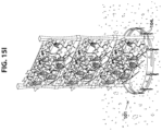
- FIG. 13 A and FIG. 14 illustrate cross-sectional views of the root-gripping barrier and the plates, retaining water, and being secured by the mass of soil, respectively.
- FIG. 13 B illustrates a cross-sectional view of the root-gripping barrier and the plates, demonstrating anti-digging function for repelling unwanted pests.
- FIG. 15 C illustrates a perspective view of the six-device-in-one landscape barrier demonstrating how the barrier-locking tongues securely integrate a solar light.
- FIG. 15 E illustrates a perspective view of the six-device-in-one landscape barrier demonstrating how the barrier-locking tongues securely integrate multiple solar lights and how two double-angled sheaths with three triple-angled sheaths securely integrate a solar light.
- FIG. 15 F illustrates a perspective view of the six-device-in-one landscape barrier demonstrating how the barrier-locking tongues securely integrate multiple solar lights and how two double-angled sheaths with three triple-angled sheaths securely integrate a solar light.
- FIG. 15 G illustrates a perspective view of the six-device-in-one landscape barrier demonstrating how the barrier-locking tongues securely integrate multiple umbrella poles.
- FIG. 15 H illustrates a perspective view of the six-device-in-one landscape barrier demonstrating how the barrier-locking tongues securely integrate a sprinkler or drip system.
- FIG. 15 I illustrates a perspective view of the six-device-in-one landscape barrier demonstrating how the barrier-locking tongues securely integrate multiple a trellis.
- FIG. 15 J and FIG. 15 K illustrate perspective views of the six-device-in-one landscape barrier demonstrating how the corner-angling holes can support a garden-plant cage.
- FIG. 15 L illustrates a perspective view of the six-device-in-one landscape barrier demonstrating how the barrier-locking stake systems can securely stack multiple barriers vertically and installed on a flat or a sloped surface.
- FIG. 15 M and FIG. 15 N illustrate top ad perspective views of the six-device-in-one landscape barrier demonstrating how the safety ridge and a strap can securely connect multiple barriers together.
- FIG. 15 O and FIG. 15 P illustrate perspective and back views of the six-device-in-one landscape barrier demonstrating how the barrier-locking stake systems can securely connect barriers to the utility holes of a pickup truck.
- FIG. 15 Q and FIG. 15 R illustrate perspective views demonstrating how multiple six-device-in-one landscape barriers can be connected by inserting a strap through the two double-angled sheaths and the three triple-angled sheaths.
- FIG. 15 S illustrates a perspective view of the six-device-in-one landscape barrier demonstrating how the barriers can be connected and used as tonneau cover of a pickup truck.
- FIG. 15 T , FIG. 15 U , FIG. 15 V , and FIG. 15 W illustrate perspective and close-up views of the six-device-in-one landscape barrier demonstrating how the barriers can be connected and used as a shield to protect trees from animals.
- FIG. 16 A , FIG. 16 B , FIG. 16 C , and FIG. 16 D illustrate perspective and close-up views of the six-device-in-one landscape barrier demonstrating how the barriers can be connected and used as a shield to protect garden plants from animals.
- FIG. 16 E illustrates a front view of a variation of the barrier system.
- FIG. 17 A and FIG. 17 B illustrate front views of variations of the fold-over safety ridge and the adjustable-corner-angling holes sets.
- FIG. 18 illustrates a front view of a variation of the top plate-securing hooks.
- FIG. 19 illustrates a front view of a variation of the two curved guiding walls.
- FIG. 20 illustrates a front view of a variation of the barrier-locking stake systems.
- FIG. 21 A , FIG. 21 B , FIG. 21 C , and FIG. 21 D illustrate front and top views of variations of the barrier systems.
- FIG. 22 A , FIG. 22 B , FIG. 22 C , FIG. 22 D , and FIG. 22 E illustrate perspective, front, side and top cross-sectional views of a variation of the barrier-locking stake systems.
- FIG. 22 F , FIG. 22 G , FIG. 22 H , FIG. 22 I , FIG. 22 J , FIG. 22 K , FIG. 22 L , FIG. 22 M , and FIG. 22 N illustrate top, front, top cross-sectional and perspective views of variations of the barrier systems.
- FIG. 22 O , FIG. 22 P , FIG. 22 Q , FIG. 22 R , FIG. 22 S , and FIG. 22 T illustrate perspective and front views of a variation of the six-device-in-one landscape barrier having two safety ridges on the top and bottom, respectively.
- FIG. 23 A , FIG. 23 B , FIG. 23 C , FIG. 23 D , FIG. 23 E , FIG. 23 F , FIG. 23 G , FIG. 23 H , FIG. 23 I , FIG. 23 J , FIG. 23 K , FIG. 23 L , FIG. 23 M , and FIG. 23 N illustrate equivalent variations of the six-device-in-one landscape barrier.
- the six-device-in-one landscape barrier comprises:
- FIG. 1 A Prior Art
- FIG. 1 B Prior Art
- FIG. 1 C Prior Art
- FIG. 1 D Prior Art
- FIG. 1 E Prior Art
- FIG. 1 F FIG. 1 G
- FIG. 1 J FIG. 1 K
- FIG. 2 A Prior Art
- FIG. 2 B Prior Art
- FIG. 2 C Prior Art
- FIG. 2 D FIG. 2 E
- FIG. 2 F FIG. 2 G
- FIG. 2 K Prioror Art
- FIG. 2 C Prioror Art
- FIG. 1 A Prior Art
- FIG. 1 B Prior Art
- FIG. 1 C Prior Art
- FIG. 1 D Prior Art
- FIG. 1 E Prior Art
- FIG. 1 F FIG. 1 G
- FIG. 1 J FIG. 1 K
- FIG. 2 A Prior Art
- FIG. 2 B Prior Art
- FIG. 2 C Prior Art
- FIG. 2 D FIG. 2 E
- FIG. 2 F FIG. 2 G
- FIG. 2 K Prioror Art
- FIG. 2 C Prioror Art
- FIG. 1 A Prior Art
- FIG. 1 B Prior Art
- FIG. 1 C Prior Art
- FIG. 1 D Prior Art
- FIG. 1 E Prior Art
- FIG. 1 F FIG. 1 G
- FIG. 1 J FIG. 1 K
- FIG. 2 A Prior Art
- FIG. 2 B Prior Art
- FIG. 2 C Prior Art
- FIG. 2 D FIG. 2 E
- FIG. 2 F FIG. 2 G
- FIG. 2 K Prioror Art
- FIG. 2 C Prioror Art
- FIG. 1 A Prior Art
- FIG. 1 B Prior Art
- FIG. 1 C Prior Art
- FIG. 1 D Prior Art
- FIG. 1 E Prior Art
- FIG. 1 F FIG. 1 G
- FIG. 1 J FIG. 1 K
- FIG. 2 A Prior Art
- FIG. 2 B Prior Art
- FIG. 2 C Prior Art
- FIG. 2 D FIG. 2 E
- FIG. 2 F FIG. 2 G
- FIG. 2 K Prioror Art
- FIG. 2 C Prioror Art
- FIG. 10 FIG. 11 A , FIG. 11 B , FIG. 11 C , FIG. 11 D , FIG. 12 A , FIG. 12 B , FIG. 12 C , FIG. 12 D , FIG. 12 E , FIG. 13 A , FIG. 13 B , FIG.
- FIG. 23 B FIG. 23 C , FIG. 23 D , FIG. 23 E , FIG. 23 F , FIG. 23 G , FIG. 23 H , FIG. 23 I , FIG. 23 J , FIG. 23 K , FIG. 23 L , FIG. 23 M , and FIG. 23 N :
- FIG. 16 illustrates a front view of a variation of barrier system 101 with a variation of the serpentine stakes 116 a.
- FIG. 17 A and FIG. 17 B illustrate front views of variations of tongue-locking openings 103 b , barrier-locking tongues 104 , and corner-angling holes 106 .
- FIG. 18 illustrates a front view of a variation of top plate-securing hooks 123 , securing anti-digging plate systems 120 to root-gripping barrier 102 .
- FIG. 19 illustrates a front view of a variation of two angled guiding walls 112 .
- FIG. 20 illustrates a front view of a variation of barrier-locking stake system 115 .
- FIG. 21 A , FIG. 21 B , FIG. 21 C , and FIG. 21 D illustrate front and top views of variations of barrier system 101 .
- FIG. 22 A , FIG. 22 B , FIG. 22 C , FIG. 22 D and FIG. 22 E illustrate perspective, front, side and cross-sectional views of a variation of barrier-locking stake system 115 .
- FIG. 22 F and FIG. 22 G illustrate top and front views of a variation of barrier system 101 .
- FIG. 22 H illustrates a side cross-sectional view demonstrating how a variation of barrier-locking stake system 115 having a recess in a variation of serpentine ridges 117 which allows three single-angled sheaths 109 to lock the stake in place during shipping and in retail environments.
- FIG. 22 I and FIG. 22 J illustrate perspective views demonstrating how a variation of barrier-locking stake system 115 are attached to a variation of barrier system 101 .
- FIG. 22 K illustrates a variation of how a variation of a stake is used to stabilize a barrier.
- FIG. 22 L illustrates variations of tongue-locking openings 103 b , and barrier-locking tongues 104 .
- FIG. 22 M illustrates a variation of the six-device-in-one landscape barrier and how the stakes are installed to connect multiple sections together and to secure the landscape barrier to the ground.
- FIG. 22 N illustrates how a variation of barrier-locking stake system 115 , having a stopper, is which prevents the stake from proceeding further past the top front edge of the top sheath.
- FIG. 22 O , FIG. 22 P , FIG. 22 Q , and FIG. 22 R illustrate variations of the six-device-in-one landscape barrier having two safety ridges on the top and bottom, respectively.
- FIG. 23 A , FIG. 23 B , FIG. 23 C , FIG. 23 D , FIG. 23 E , FIG. 23 F , FIG. 23 G , FIG. 23 H , FIG. 23 I , FIG. 23 J , FIG. 23 K , FIG. 23 L , FIG. 23 M , and FIG. 23 N illustrate equivalent variations of the six-device-in-one landscape barrier.
- the present invention substantially departs from the conventional concepts and designs of the prior art. In doing so, the present invention provides a six-device-in-one landscape barrier, having many unique and significant features, functions, and advantages, which overcome all the disadvantages of the prior art, as follows:
Landscapes
- Life Sciences & Earth Sciences (AREA)
- Environmental Sciences (AREA)
- Engineering & Computer Science (AREA)
- General Health & Medical Sciences (AREA)
- Toxicology (AREA)
- Health & Medical Sciences (AREA)
- Zoology (AREA)
- Birds (AREA)
- Insects & Arthropods (AREA)
- Pest Control & Pesticides (AREA)
- Wood Science & Technology (AREA)
- Mechanical Engineering (AREA)
- General Engineering & Computer Science (AREA)
- Transportation (AREA)
- Combustion & Propulsion (AREA)
- Chemical & Material Sciences (AREA)
- Heat Treatment Of Sheet Steel (AREA)
- Cultivation Of Plants (AREA)
- Sustainable Development (AREA)
- Water Supply & Treatment (AREA)
- Cultivation Receptacles Or Flower-Pots, Or Pots For Seedlings (AREA)
Abstract
Description
-
- 1) Barrier system,
- 2) Stake-locking sheath system,
- 3) Barrier-locking stake system,
- 4) Serpentine ridge system, and
- 5) Anti-digging plate system.
-
- 1) No prior art mention or disclose any landscape edging, having
- barrier-locking
tongues 104. - Therefore, the prior art of landscape edging:
- a) Cannot save money for the consumer, requiring less barrier sections because of less overlap at barrier ends in the directions of
arrows - (see
FIG. 1A (Prior Art),FIG. 1B (Prior Art),FIG. 1C (Prior Art),FIG. 1D ,FIG. 1E (Prior Art),FIG. 1G (Prior Art),FIG. 1H , FIG.
- (see
- b) Cannot save materials during manufacturing being one-quarter of the length of wasted steel materials as comparable prior art in the directions of
arrows - (see
FIG. 1A (Prior Art),FIG. 1B (Prior Art),FIG. 1C (Prior Art),FIG. 1D ,FIG. 1E (Prior Art),FIG. 1G (Prior Art),FIG. 1H ,FIG. 2C (Prior Art), andFIG. 2D );
- (see
- c) Cannot securely support
- solar-stake-mounted
lights 100 e - (see
FIGS. 3B, 3C, and 3D ), - a trellis for vines or climbing plants
- (see
FIG. 3H , andFIG. 15I ), - an umbrella pole
- (see
FIG. 3F , andFIG. 15G ), and - a sprinkler head or drip line
- (see
FIG. 3G , andFIG. 15H );
- solar-stake-mounted
- d) Cannot securely connect multiple six-device-in-one landscape barriers to each other by inserting through tongue-locking
openings 103 b and wrapping over the top or under the bottom of root-grippingbarrier 102, respectively- (see
FIG. 1D ,FIG. 6E ,FIG. 6F , andFIG. 6G );
- (see
- e) Cannot securely lock multiple six-device-in-one landscape barriers to each other by inserting through tongue-locking
openings 103 b, wrapping in the opposite direction through corner-anglingholes 106, and again through tongue-lockingopenings 103 b- in the directions of
arrows - (see
FIG. 8A ,FIG. 8B ,FIG. 8C , andFIG. 8D );
- in the directions of
- f) Cannot anchor six-device-in-one landscape barrier to the soil
- (see
FIG. 15U ,FIG. 15W , andFIG. 16D ); and
- (see
- g) Cannot protect garden plants from animals
- (see
FIG. 16B );
- (see
- a) Cannot save money for the consumer, requiring less barrier sections because of less overlap at barrier ends in the directions of
- barrier-locking
- 2) No prior art mention or disclose any landscape edging, having
-
safety ridge 105. - Therefore, the prior art of landscape edging:
- a) Cannot connect a
safety ridge 105 of one six-device-in-one landscape barrier to asafety ridge 105 of a second six-device-in-one landscape barrier in the directions ofarrows 134- (see
FIG. 15L ) - to create a shield to protect garden plants from animals
- (see
FIG. 15T andFIG. 15U ), - to create a shield to protect saplings from animals
- (see
FIG. 15R ), - to create a shield to protect trees from animals
- (see
FIG. 15S ), - to create a barrier to protect garden vegetation from animals
- (see
FIG. 15V ), and - to create a tonneau cover of a truck bed
- (see
FIG. 15Q );
- (see
- b) Cannot provide a mechanical stopper or buttress against an adjacent
horizontal safety ridge 105, while coupling such, in the directions ofarrows - (see
FIG. 8A andFIG. 8B );
- (see
- c) Cannot position the horizontal center of joining location of
adjacent safety ridge 105 to be above a vertical row of adjustable-corner-anglingholes 106 thereby structurally assisting the malleability of a bending point of material-saving multi-root-gripping-and-water-flowingbarrier 102- (see
FIG. 8A andFIG. 8B ); and
- (see
- d) Cannot provide means for installing
barrier system 101 to quickly and easily couple barrier-lockingtongues 104 to a respective tongue-lockingopenings 103 b in the directions ofarrows - (see
FIG. 8A andFIG. 8B ).
- (see
- a) Cannot connect a
-
- 3) No prior art mention or disclose any landscape edging, having
- angling end-
wing 103 a. - Therefore, the prior art of landscape edging:
- a) Cannot save manufacturing materials being one-quarter of the length of wasted steel materials as comparable prior art in the directions of
arrows - (see
FIG. 1A (Prior Art),FIG. 1B (Prior Art),FIG. 1C (Prior Art),FIG. 1D ,FIG. 1E (Prior Art),FIG. 1G (Prior Art),FIG. 1H ,FIG. 2C (Prior Art), andFIG. 2D );
- (see
- b) Cannot save money for consumer, requiring less barrier sections because of less overlap at barrier ends in the directions of
arrows - (see
FIG. 1A (Prior Art),FIG. 1B (Prior Art),FIG. 1C (Prior Art),FIG. 1D ,FIG. 1E (Prior Art),FIG. 1G (Prior Art),FIG. 1H ,FIG. 2C (Prior Art), andFIG. 2D );
- (see
- c) Cannot slide into the fold-over multi-barrier-
coupling safety ridge 105 of an additional adjacent six-device-in-one landscape barrier; - d) Cannot anchor the six-device-in-one landscape barrier into the ground, when positioned vertically
- (see
FIG. 15R ,FIG. 15S , andFIG. 15V ); and
- (see
- c) Cannot prevent animals from digging beneath the six-device-in-one landscape barrier, when inserted into the soil vertically
- (see
FIG. 15R ,FIG. 15S , andFIG. 15V ).
- (see
- a) Cannot save manufacturing materials being one-quarter of the length of wasted steel materials as comparable prior art in the directions of
- angling end-
- 4) No prior art mention or disclose any landscape edging, having corner-angling
holes 106.- Therefore, the prior art of landscape edging:
- a) Cannot lock a six-device-in-one landscape barrier to an additional adjacent six-device-in-one landscape barrier by interlocking barrier-locking
tongues 104 there through- (see
FIG. 8B ,FIG. 8C , andFIG. 8D );
- (see
- b) Cannot lockingly support a garden-plant cage
- (see
FIG. 2E ,FIG. 2F ,FIG. 15J , andFIG. 15K ); and
- (see
- c) Cannot promote bending angling end-
wing 103 a to form a corner, enablingbarrier system 101 to create a variety of corner-angles.- (see
FIG. 2L ,FIG. 2M ,FIG. 2N ,FIG. 2Q , andFIG. 2R ).
- (see
- a) Cannot lock a six-device-in-one landscape barrier to an additional adjacent six-device-in-one landscape barrier by interlocking barrier-locking
- Therefore, the prior art of landscape edging:
- 5) No prior art mention or disclose any landscape edging, having
-
serpentine stake 116 a. - Therefore, the prior art of landscape edging:
- a) Cannot frictionally anchor into the soil;
- (see
FIG. 10 )
- (see
- b) Can secure
barrier system 101 into the soil, on an inclined surface- (see
FIG. 2A (Prior Art), andFIG. 6G );
- (see
- c) Cannot
secure barrier system 101 into the soil on a level surface- (see
FIG. 6E , andFIG. 10 );
- (see
- d) Cannot
secure barrier system 101 piercing into soil angledly in the directions ofarrows 126- (see
FIG. 6F , andFIG. 6G ); and
- (see
- e) Cannot
secure barrier system 101 piercing into the soil vertically in the directions ofarrows 125- (see
FIG. 6E , andFIG. 10 ).
- (see
- a) Cannot frictionally anchor into the soil;
-
- 6) No prior art mention or disclose any landscape edging, having
-
serpentine ridges 118 a. - Therefore, the prior art of landscape edging:
- a) Cannot wedge into three single-angled
sheaths 109 to securely lockserpentine stake 116 a, for storage and shipping- (see
FIG. 4B ,FIG. 7B , andFIG. 7E );
- (see
- b) Cannot wedge into two double-
angled sheaths 110 to securely lockserpentine stake 116 a- (see
FIG. 6C ,FIG. 6D ,FIG. 7B , andFIG. 7C );
- (see
- c) Cannot wedge into three triple-angled
serpentine stake 116 a- (see
FIG. 6C ,FIG. 6D ,FIG. 7B ,FIG. 7D , andFIG. 7E );
- (see
- d) Cannot frictionally secure
serpentine stake 116 a into the soil to prevent lifting when ground expands and contracts due changes in temperature in the directions ofarrows - (see
FIG. 1K (Prior Art),FIG. 2A (Prior Art),FIG. 2B (Prior Art), andFIG. 7A ); and
- (see
- e) Cannot lockingly secure
serpentine stake 116 a to root-grippingbarrier 102 by snap-locking double-snap-locking recesses to three triple-angled sheaths 113- (see
FIG. 22A andFIG. 22B ).
- (see
- a) Cannot wedge into three single-angled
-
- 7) No prior art mention or disclose any landscape edging, having
- root-gripping
locking tunnels 119. - Therefore, the prior art of landscape edging:
- a) Cannot secure
serpentine stake 116 a in the soil by providing an opening through which grass andplant roots 128 a may grow in the directions ofarrows 128 b- (see
FIG. 2 (Prior Art), andFIG. 10 );
- (see
- b) Cannot create friction against the soil to secure
serpentine stake 116 a- (see
FIG. 10 );
- (see
- c) Cannot secure root-gripping
barrier 102 in the soil by providing an opening through which grass andplant roots 128 a may grow in the directions ofarrows 128 b- (see
FIG. 2 (Prior Art), andFIG. 10 ); and
- (see
- d) Cannot create friction against the soil to secure root-gripping
barrier 102- (see
FIG. 10 ).
- (see
- a) Cannot secure
- root-gripping
- 8) No prior art mention or disclose any landscape edging, having
- stake-locking root-gripping
holes 116 c. - Therefore, the prior art of landscape edging:
- a) Cannot lock barrier-locking
stake system 115 tobarrier system 101 by securing to stake-lockingnipples 107 b- (see
FIG. 4D );
- (see
- b) Cannot secure
serpentine stake 116 a in the soil by providing an opening through which grass andplant roots 128 a may grow in the directions ofarrows 128 b- (see
FIG. 2 (Prior Art), and 10); and
- (see
- c) Cannot create friction against the soil to secure multi-barrier-locking-angle multi-root-gripping-angle multi-water-flowing-angle storage-lockable-for-
shipping serpentine stake 116 a- (see
FIG. 10 ).
- (see
- a) Cannot lock barrier-locking
- stake-locking root-gripping
- 9) No prior art mention or disclose any landscape edging, having
- three root-gripping
angle tunnels 107 a. - Therefore, the prior art of landscape edging:
- a) Cannot save materials during manufacturing by stamping out
serpentine stake 116 a from material-saving multi-root-gripping-and-water-flowingbarrier 102, utilizing the subsequent empty space therefrom- (see
FIG. 1A (Prior Art), andFIG. 6A );
- (see
- b) Cannot save time and energy costs when barrier-locking
stake systems 115 is stored within root-grippingangle tunnels 107 a during packaging, storage, and shipping the six-device-in-one landscape barrier- to reduce the space the space needed in each shipping container (see
FIG. 2C andFIG. 2D ), - to reduce the space needed for
barrier system 101 thickness when packaged, and - to reduce significantly the unit cost of the six-device-in-one landscape barrier,
- (
FIG. 2C (PRIOR ART) illustrates ashipping container 99 a has one hundred landscape barrier packagedunits 99 b filling up all itsinternal volume 99 c), - (
FIG. 2D illustrates ashipping container 100 a has one hundred landscape barrier packagedunits 100 b filling up only 70% of itsinternal volume 100 c and saving 30% of itsinternal volume 100 d);
- to reduce the space the space needed in each shipping container (see
- c) Cannot secure root-gripping
barrier 102 into the soil by providing an opening through which grass andplant roots 128 a may grow in the directions ofarrows 128 b- (see
FIG. 6A ,FIG. 6B ,FIG. 9 , andFIG. 10 );
- (see
- d) Cannot secure root-gripping
barrier 102 into the soil by providing an opening through which soil may fill in the directions ofarrows - (see
FIG. 15A );
- (see
- c) Cannot lock into the soil by providing a lower edge below root-gripping
angle tunnels 107 a in the directions ofarrows 133- (see
FIG. 15B );
- (see
- f) Cannot lock to top plate-securing
hooks 123, in the directions ofarrows - (see
FIG. 9 ,FIG. 11A ,FIG. 11B ,FIG. 11C ,FIG. 11D ,FIG. 13 , andFIG. 15A ); and
- (see
- g) Cannot lock to bottom plate-securing snap-
hooks 124, in the directions ofarrows - (see
FIG. 9 ,FIG. 11A ,FIG. 11B ,FIG. 11C ,FIG. 11D ,FIG. 13 , andFIG. 15A ).
- (see
- a) Cannot save materials during manufacturing by stamping out
- three root-gripping
- 10) No prior art mention or disclose any landscape edging, having
- stake-locking
nipples 107 b. - Therefore, the prior art of landscape edging:
- a) Cannot lock the stake tip to
barrier system 101 by being inserted into stake-locking root-grippingholes 116 c- (see
FIG. 4D ) - to store the multi-barrier-locking-angle multi-root-gripping-angle multi-water-flowing-angle storage-lockable-for-shipping
serpentine stake system 115;
- (see
- b) Cannot lock the stake tip to
barrier system 101 by being inserted into stake-locking root-grippingholes 116 c- (see
FIG. 4D ) - to provide a secure place to store barrier-locking
stake system 115 when not in use; and
- (see
- c) Cannot lock the stake tip to
barrier system 101 by being inserted into stake-locking root-grippingholes 116 c- (see
FIG. 4D ) - to prevent loss of
serpentine stake 116 a.
- (see
- a) Cannot lock the stake tip to
- stake-locking
- 11) No prior art mention or disclose any landscape edging, having
- three single-angled
sheaths 109. - Therefore, the prior art of landscape edging:
- a) Cannot wedge the
serpentine ridges 118 a to securely lockserpentine stake 116 a tobarrier system 101- (see
FIG. 6A ,FIG. 7B ,FIG. 7C ,FIG. 7D , andFIG. 7E ); and
- (see
- b) Cannot secure
serpentine stake 116 a to material-saving multi-root-gripping-and-water-flowingbarrier 102 for storage and shipping- (see
FIG. 4B ).
- (see
- a) Cannot wedge the
- three single-angled
- 12) No prior art mention or disclose any landscape edging, having
- two double-
angled sheaths 110. - Therefore, the prior art of landscape edging:
- a) Cannot secure multiple six-device-in-one landscape barrier adjacently by providing loops for a
strap 100 h to be threaded through in the direction ofarrows 134- (see
FIG. 15N , andFIG. 15O ) - to create a shield to protect garden plants from animals
- (see
FIG. 16A andFIG. 16B ), - to create a shield to protect saplings from animals
- (see
FIG. 15S andFIG. 15T ), - to create a shield to protect trees from animals
- (see
FIG. 15S ,FIG. 15T ,FIG. 15U , andFIG. 15V ), - to create a barrier to protect garden vegetation from animals
- (see
FIG. 16C andFIG. 16D ), and - to create a tonneau cover of a truck bed
- (see
FIG. 15R );
- (see
- b) Cannot secure six-device-in-one landscape barriers to utility holes of a pickup truck by providing openings for
serpentine stake 116 a- to create a vertical truck-bed extender
- (see
FIG. 15P , andFIG. 15Q );
- c) Cannot secure multiple six-device-in-one landscape barriers to each other vertically by providing openings for
serpentine stake 116 a- to create a tree ring or planter ring of varying heights
- (see
FIG. 15J ,FIG. 15K ,FIG. 15L , andFIG. 15M );
- d) Cannot guide
serpentine stake 116 a while being inserted vertically in the directions ofarrows 125- (see
FIG. 6D andFIG. 6E ); and
- (see
- e) Cannot guide
serpentine stake 116 a while being inserted angledly in the directions ofarrows 126- (see
FIG. 6C ,FIG. 6F , andFIG. 6G ).
- (see
- a) Cannot secure multiple six-device-in-one landscape barrier adjacently by providing loops for a
- two double-
- 13) No prior art mention or disclose any landscape edging, having
- two vertical guiding
walls 111. - Therefore, the prior art of landscape edging:
- a) Cannot guide
serpentine stake 116 a while being inserted vertically through two double-angled sheaths 110- (see
FIG. 6D ,FIG. 6E , andFIG. 10 ); and
- (see
- b) Cannot stabilize
serpentine stake 116 a in the soil- (see
FIG. 6D ,FIG. 6E , andFIG. 10 ).
- (see
- a) Cannot guide
- two vertical guiding
- 14) No prior art mention or disclose any landscape edging, having
- two angled guiding
walls 112. - Therefore, the prior art of landscape edging:
- a) Cannot guide
serpentine stake 116 a while being inserted angledly through two double-angled sheaths 110- (see
FIG. 6C ,FIG. 6F , andFIG. 6G ); and
- (see
- b) Cannot stabilize
serpentine stake 116 a in the soil- (see
FIG. 6C , andFIG. 6G ).
- (see
- a) Cannot guide
- two angled guiding
- 15) No prior art mention or disclose any landscape edging, having
- three triple-
angled sheaths 113. - Therefore, the prior art of landscape edging:
- a) Cannot stackedly connect six-device-in-one landscape barriers adjacently by providing loops for a
strap 100 h can be threaded through in the direction ofarrows 135- (see
FIG. 15N , andFIG. 15O ) - to create a shield to protect garden plants from animals
- (see
FIG. 16A andFIG. 16B ), - to create a shield to protect saplings from animals
- (see
FIG. 15S andFIG. 15T ), - to create a shield to protect trees from animals
- (see
FIG. 15U andFIG. 15V ), - to create a barrier to protect garden vegetation from animals
- (see
FIG. 16C andFIG. 16D ), and - to create a tonneau cover of a truck bed
- (see
FIG. 15R );
- (see
- b) Cannot secure six-device-in-one landscape barriers to utility holes of a pickup truck by providing openings for
serpentine stake 116 a- to create a vertical truck-bed extender
- (see
FIG. 15P , andFIG. 15Q );
- c) Cannot secure multiple six-device-in-one landscape barriers to each other vertically by providing openings for
serpentine stake 116 a- to create a tree ring or planter ring of varying heights
- (see
FIG. 15J ,FIG. 15K ,FIG. 15L , andFIG. 15M );
- d) Cannot stabilize the tip of
serpentine stake 116 a to root-grippingbarrier 102 while securely wedged into three single-angledsheaths 109, for storage and shipping- (see
FIG. 4B );
- (see
- e) Cannot guide
serpentine stake 116 a while being inserted through two double-angled sheaths 110 angledly in the direction ofarrows 126- (see
FIG. 6C ,FIG. 6F , andFIG. 6G ); and
- (see
- f) Cannot guide
serpentine stake 116 a while being inserted vertically through two double-angled sheaths 110 in the direction ofarrows 125- (see
FIG. 6D , andFIG. 6E ).
- (see
- a) Cannot stackedly connect six-device-in-one landscape barriers adjacently by providing loops for a
- three triple-
- 16) No prior art mention or disclose any landscape edging, having
- two curved guiding
walls 114. - Therefore, the prior art of landscape edging:
- a) Cannot guide
serpentine stake 116 a while being inserted vertically through the three triple-angled sheaths 113- (see
FIG. 6C ,FIG. 6D ,FIG. 6E , andFIG. 7D );
- (see
- b) Cannot guide
serpentine stake 116 a while being inserted angledly through the three triple-angled sheaths 113- (see
FIG. 6C ,FIG. 6F ,FIG. 6G , andFIG. 7D ); and
- (see
- c) Cannot stabilize
serpentine stake 116 a in the soil- (see
FIG. 6C , andFIG. 6G ).
- (see
- a) Cannot guide
- two curved guiding
- 17) No prior art mention or disclose any landscape edging, having
-
anti-digging plates 121. - Therefore, the prior art of landscape edging:
- a)
Cannot retain water 130 to help nourish grass and plants- (see
FIG. 13A );
- (see
- b) Cannot prevent animals from digging underneath the six-device-in-one landscape barrier
- (see
FIG. 13B andFIG. 16B );
- (see
- c) Cannot stabilize six-device-in-one
barrier system 101 by soil, gravel, rocks, bark chips, or other landscaping materials, being amassed uponplates 121, creating a downward force in the directions ofarrows 131- (see
FIG. 13A andFIG. 14 );
- (see
- d) Cannot provide adjustability, to be configured to many respective custom curvatures
- (see
FIG. 3B ,FIG. 12A ,FIG. 12B ,FIG. 12C ,FIG. 12D , andFIG. 12E );
- (see
- e) Cannot provide adjustability, to be configured in a straight line
- (see
FIG. 5A , andFIG. 12B ); and
- (see
- f) Cannot provide adjustability, to be configured with 90, 45, 30, and 15 degree corners
- (see
FIG. 3B ,FIG. 12B , andFIG. 12E ).
- (see
- a)
-
- 18) No prior art mention or disclose any landscape edging, having
- top plate-securing hooks 123.
- Therefore, the prior art of landscape edging:
- a) Cannot snappingly attach to
barrier system 101 in the direction ofarrows - (see
FIG. 5A ,FIG. 5B ,FIG. 5C ,FIG. 11A ,FIG. 11B ,FIG. 11C , andFIG. 11D );
- (see
- b) Cannot quickly and easily remove from
anti-digging plate systems 120 tobarrier system 101- (see
FIG. 11A ,FIG. 11B ,FIG. 11C , andFIG. 11D );
- (see
- c) Cannot quickly and easily attach to
anti-digging plate systems 120 frombarrier system 101- (see
FIG. 5A ,FIG. 5B , andFIG. 5C ); and
- (see
- d) Cannot securely attach barrier-conforming
connector 122, to root-grippingbarrier 102- (see
FIG. 11D ).
- (see
- a) Cannot snappingly attach to
- 19) No prior art mention or disclose any landscape edging, having
- bottom plate-securing snap-hooks 124.
- Therefore, the prior art of landscape edging:
- a) Cannot snappingly attach barrier-conforming
connector 122, to root-grippingbarrier 102 in the direction ofarrows - (see
FIG. 11A ,FIG. 11B ,FIG. 11C , andFIG. 11D );
- (see
- b) Cannot quickly and easily remove from
barrier system 101- (see
FIG. 5A ,FIG. 5B ,FIG. 5C , andFIG. 11D );
- (see
- c) Cannot quickly and easily attach to
barrier system 101- (see
FIG. 11C andFIG. 11D ); and
- (see
- d) Cannot securely attach barrier-conforming
connector 122, to material-saving multi-root-gripping-and-water-flowingbarrier 102- (see
FIG. 11D ).
- (see
- a) Cannot snappingly attach barrier-conforming
- 1) No prior art mention or disclose any landscape edging, having
-
- 1) It is an object of the new invention to provide a six-device-in-one landscape barrier, having
- barrier-locking
tongues 104. - Therefore, the six-device-in-one landscape barrier:
- a) Can save money for the consumer, requiring less barrier sections because of less overlap at barrier ends in the directions of
arrows - (see
FIG. 1A (Prior Art),FIG. 1B (Prior Art),FIG. 1C (Prior Art),FIG. 1D ,FIG. 1E (Prior Art),FIG. 1G (Prior Art),FIG. 1H ,FIG. 2C (Prior Art), andFIG. 2D );
- (see
- b) Can save materials during manufacturing being one-quarter of the length of wasted steel materials as comparable prior art in the directions of
arrows - (see
FIG. 1A (Prior Art),FIG. 1B (Prior Art),FIG. 1C (Prior Art),FIG. 1D ,FIG. 1E (Prior Art),FIG. 1G (Prior Art),FIG. 1H ,FIG. 2C (Prior Art), andFIG. 2D );
- (see
- c) Can securely support
- solar-stake-mounted
lights 100 e - (see
FIGS. 3B, 3C, and 3D ), - a trellis for vines or climbing plants
- (see
FIG. 3H , andFIG. 15I ), - an umbrella pole
- (see
FIG. 3F , andFIG. 15G ), and - a sprinkler head or drip line
- (see
FIG. 3G , andFIG. 15H );
- solar-stake-mounted
- d) Can securely connect multiple six-device-in-one landscape barriers to each other by inserting through tongue-locking
openings 103 b and wrapping over the top or under the bottom of root-grippingbarrier 102, respectively- (see
FIG. 1D ,FIG. 6E ,FIG. 6F , andFIG. 6G );
- (see
- e) Can securely lock multiple six-device-in-one landscape barriers to each other by inserting through tongue-locking
openings 103 b, wrapping in the opposite direction through corner-anglingholes 106, and again through tongue-lockingopenings 103 b- in the directions of
arrows - (see
FIG. 8A ,FIG. 8B ,FIG. 8C , andFIG. 8D );
- in the directions of
- f) Can anchor six-device-in-one landscape barrier to the soil
- (see
FIG. 15U ,FIG. 15W , andFIG. 16D ); and
- (see
- g) Can protect garden plants from animals
- (see
FIG. 16B ).
- (see
- a) Can save money for the consumer, requiring less barrier sections because of less overlap at barrier ends in the directions of
- barrier-locking
- 2) It is an object of the new invention to provide a six-device-in-one landscape barrier, having
-
safety ridge 105. - Therefore, the six-device-in-one landscape barrier:
- a) Can connect a
safety ridge 105 of one six-device-in-one landscape barrier to asafety ridge 105 of a second six-device-in-one landscape barrier in the directions ofarrows 134- (see
FIG. 15L ) - to create a shield to protect garden plants from animals
- (see
FIG. 15T andFIG. 15U ), - to create a shield to protect saplings from animals
- (see
FIG. 15R ), - to create a shield to protect trees from animals
- (see
FIG. 15S ), - to create a barrier to protect garden vegetation from animals
- (see
FIG. 15V ), and - to create a tonneau cover of a truck bed
- (see
FIG. 15Q );
- (see
- b) Can provide a mechanical stopper or buttress against an adjacent
horizontal safety ridge 105, while coupling such, in the directions ofarrows - (see
FIG. 8A andFIG. 8B );
- (see
- c) Can position the horizontal center of joining location of
adjacent safety ridge 105 to be above a vertical row of adjustable-corner-anglingholes 106 thereby structurally assisting the malleability of a bending point of root-grippingbarrier 102- (see
FIG. 8A andFIG. 8B ); and
- (see
- d) Can provide means for installing
barrier system 101 to quickly and easily couple barrier-lockingtongues 104 to a respective tongue-lockingopenings 103 b in the directions ofarrows - (see
FIG. 8A andFIG. 8B ).
- (see
- a) Can connect a
-
- 3) It is an object of the new invention to provide a six-device-in-one landscape barrier, having
- angling end-
wing 103 a. - Therefore, the six-device-in-one landscape barrier:
- a) Can save manufacturing materials being one-quarter of the length of wasted steel materials as comparable prior art in the directions of
arrows - (see
FIG. 1A (Prior Art),FIG. 1B (Prior Art),FIG. 1C (Prior Art),FIG. 1D ,FIG. 1E (Prior Art),FIG. 1G (Prior Art),FIG. 1H ,FIG. 2C (Prior Art), andFIG. 2D );
- (see
- b) Can save money for consumer, requiring less barrier sections because of less overlap at barrier ends in the directions of
arrows - (see
FIG. 1A (Prior Art),FIG. 1B (Prior Art),FIG. 1C (Prior Art),FIG. 1D ,FIG. 1E (Prior Art),FIG. 1G (Prior Art),FIG. 1H ,FIG. 2C (Prior Art), andFIG. 2D );
- (see
- c) Can slide into
safety ridge 105 of an additional adjacent six-device-in-one landscape barrier; - d) Can anchor the six-device-in-one landscape barrier into the ground, when positioned vertically
- (see
FIG. 15R ,FIG. 15S , andFIG. 15V ); and
- (see
- c) Can prevent animals from digging beneath the six-device-in-one landscape barrier, when inserted into the soil vertically
- (see
FIG. 15R ,FIG. 15S , andFIG. 15V ).
- (see
- a) Can save manufacturing materials being one-quarter of the length of wasted steel materials as comparable prior art in the directions of
- angling end-
- 4) It is an object of the new invention to provide a six-device-in-one landscape barrier, having
- corner-angling
holes 106. - Therefore, the six-device-in-one landscape barrier:
- a) Can lock a six-device-in-one landscape barrier to an additional adjacent six-device-in-one landscape barrier by interlocking barrier-locking
tongues 104 there through- (see
FIG. 8B ,FIG. 8C , andFIG. 8D );
- (see
- b) Can lockingly support a garden-plant cage
- (see
FIG. 2E ,FIG. 2F ,FIG. 15J , andFIG. 15K ); and
- (see
- c) Can promote bending of angling end-
wing 103 a to form a corner, enablingbarrier system 101 to create a variety of corner-angles.- (see
FIG. 2L ,FIG. 2M ,FIG. 2N ,FIG. 2Q , andFIG. 2R ).
- (see
- a) Can lock a six-device-in-one landscape barrier to an additional adjacent six-device-in-one landscape barrier by interlocking barrier-locking
- corner-angling
- 5) It is an object of the new invention to provide a six-device-in-one landscape barrier, having
-
serpentine stake 116 a. - Therefore, the six-device-in-one landscape barrier:
- a) Can frictionally anchor into the soil;
- (see
FIG. 10 )
- (see
- b) Can secure
barrier system 101 into the soil, on an inclined surface- (see
FIG. 2A (Prior Art), andFIG. 6G );
- (see
- c) Can secure
barrier system 101 into the soil on a level surface- (see
FIG. 6E , andFIG. 10 );
- (see
- d) Can secure
barrier system 101 piercing into soil angledly in the directions ofarrows 126- (see
FIG. 6F , andFIG. 6G ); and
- (see
- e) Can secure
barrier system 101 piercing into the soil vertically in the directions ofarrows 125- (see
FIG. 6E , andFIG. 10 ).
- (see
- a) Can frictionally anchor into the soil;
-
- 6) It is another object of the new invention to provide a six-device-in-one landscape barrier, having
-
serpentine ridges 118 a. - Therefore, the landscape barrier:
- a) Can wedge into three single-angled
sheaths 109 to securely lockserpentine stake 116 a, for storage and shipping- (see
FIG. 4B ,FIG. 7B , andFIG. 7E );
- (see
- b) Can wedge into two double-
angled sheaths 110 to securely lockserpentine stake 116 a- (see
FIG. 6C ,FIG. 6D ,FIG. 7B , andFIG. 7C );
- (see
- c) Can wedge into three triple-
angled sheaths 113 to securely lockserpentine stake 116 a- (see
FIG. 6C ,FIG. 6D ,FIG. 7B ,FIG. 7D , andFIG. 7E );
- (see
- d) Can frictionally secure
serpentine stake 116 a into the soil to prevent lifting when ground expands and contracts due changes in temperature in the directions ofarrows - (see
FIG. 1K (Prior Art),FIG. 2A (Prior Art),FIG. 2B (Prior Art), andFIG. 7A ); and
- (see
- c) Can lockingly secure
serpentine stake 116 a to root-grippingbarrier 102 by snap-locking double-snap-locking recesses to three triple-angled sheaths 113- (see
FIG. 22A andFIG. 22B ).
- (see
- a) Can wedge into three single-angled
-
- 7) It is another object of the new invention to provide a landscape barrier, having
- root-gripping
locking tunnels 119. - Therefore, the landscape barrier:
- a) Can secure
serpentine stake 116 a in the soil by providing an opening through which grass andplant roots 128 a may grow in the directions ofarrows 128 b- (see
FIG. 2 (Prior Art), andFIG. 10 );
- (see
- b) Can create friction against the soil to secure
serpentine stake 116 a- (see
FIG. 10 );
- (see
- c) Can secure root-gripping
barrier 102 in the soil by providing an opening through which grass andplant roots 128 a may grow in the directions ofarrows 128 b- (see
FIG. 2 (Prior Art), andFIG. 10 ); and
- (see
- d) Can create friction against the soil to secure root-gripping
barrier 102- (see
FIG. 10 ).
- (see
- a) Can secure
- root-gripping
- 8) It is a further object of the new invention to provide a landscape barrier, having stake-locking root-gripping
holes 116 c.- Therefore, the landscape barrier:
- a) Can lock barrier-locking
stake system 115 tobarrier system 101 by securing to stake-lockingnipples 107 b- (see
FIG. 4D );
- (see
- b) Can secure
serpentine stake 116 a in the soil by providing an opening through which grass andplant roots 128 a may grow in the directions ofarrows 128 b- (see
FIG. 2 (Prior Art), and 10); and
- (see
- c) Can create friction against the soil to secure
serpentine stake 116 a- (see
FIG. 10 ).
- (see
- a) Can lock barrier-locking
- Therefore, the landscape barrier:
- 9) It is an even further object of the new invention to provide a six-device-in-one landscape barrier, having
- three root-gripping
angle tunnels 107 a. - Therefore, the six-device-in-one landscape barrier:
- a) Can save materials during manufacturing by stamping out
serpentine stake 116 a from root-grippingbarrier 102, utilizing the subsequent empty space therefrom- (see
FIG. 1A (Prior Art), andFIG. 6A );
- (see
- b) Can save time and energy costs when barrier-locking
stake systems 115 is stored within three root-grippingangle tunnels 107 a during packaging, storage, and shipping the six-device-in-one landscape barrier- to reduce the space the space needed in each shipping container
- (see
FIG. 2C andFIG. 2D ), - to reduce the space needed for
barrier system 101 thickness when packaged, and - to reduce significantly the unit cost of the six-device-in-one landscape barrier,
- (
FIG. 2C (PRIOR ART) illustrates ashipping container 99 a has one hundred landscape barrier packagedunits 99 b filling up all itsinternal volume 99 c), - (
FIG. 2D illustrates ashipping container 100 a has one hundred landscape barrier packagedunits 100 b filling up only 70% of itsinternal volume 100 c and saving 30% of itsinternal volume 100 d);
- c) Can secure root-gripping
barrier 102 into the soil by providing an opening through which grass andplant roots 128 a may grow in the directions ofarrows 128 b- (see
FIG. 6A ,FIG. 6B ,FIG. 9 , andFIG. 10 );
- (see
- d) Can secure root-gripping
barrier 102 into the soil by providing an opening through which soil may fill in the directions ofarrows - (see
FIG. 15A );
- (see
- e) Can lock into the soil by providing a lower edge below root-gripping
angle tunnels 107 a in the directions ofarrows 133- (see
FIG. 15B );
- (see
- f) Can lock to top plate-securing
hooks 123, in the directions ofarrows - (see
FIG. 9 ,FIG. 11A ,FIG. 11B ,FIG. 11C ,FIG. 11D ,FIG. 13 , andFIG. 15A ); and
- (see
- g) Can lock to bottom plate-securing snap-
hooks 124, in the directions ofarrows - (see
FIG. 9 ,FIG. 11A ,FIG. 11B ,FIG. 11C ,FIG. 11D ,FIG. 13 , andFIG. 15A ).
- (see
- a) Can save materials during manufacturing by stamping out
- three root-gripping
- 10) It is another object of the new invention to provide a six-device-in-one landscape barrier, having
- stake-locking
nipples 107 b. - Therefore, the six-device-in-one landscape barrier:
- a) Can lock the stake tip to
barrier system 101 by being inserted into stake-locking root-grippingholes 116 c- (see
FIG. 4D ) - to store barrier-locking
stake system 115;
- (see
- b) Can lock the stake tip to
barrier system 101 by being inserted into stake-locking root-grippingholes 116 c- (see
FIG. 4D ) - to provide a secure place to store barrier-locking
stake system 115 when not in use; and
- (see
- c) Can lock the stake tip to
barrier system 101 by being inserted into stake-locking root-grippingholes 116 c- (see
FIG. 4D ) - to prevent loss of
serpentine stake 116 a.
- (see
- a) Can lock the stake tip to
- stake-locking
- 11) It is yet another object of the new invention to provide a six-device-in-one landscape barrier, having
- three single-angled
sheaths 109. - Therefore, the six-device-in-one landscape barrier:
- a) Can wedge
serpentine ridges 118 a to securely lockserpentine stake 116 a tobarrier system 101- (see
FIG. 6A ,FIG. 7B ,FIG. 7C ,FIG. 7D , andFIG. 7E ); and
- (see
- b) Can secure
serpentine stake 116 a to root-grippingbarrier 102 for storage and shipping- (see
FIG. 4B ).
- (see
- a) Can wedge
- three single-angled
- 12) It is still yet another object of the new invention to provide a six-device-in-one landscape barrier, having
- two double-
angled sheaths 110. - Therefore, the six-device-in-one landscape barrier:
- a) Can secure multiple six-device-in-one landscape barrier adjacently by providing loops for a
strap 100 h to be threaded through in the direction ofarrows 134- (see
FIG. 15N , andFIG. 15O ) - to create a shield to protect garden plants from animals
- (see
FIG. 16A andFIG. 16B ), - to create a shield to protect saplings from animals
- (see
FIG. 15S andFIG. 15T ), - to create a shield to protect trees from animals
- (see
FIG. 15S ,FIG. 15T ,FIG. 15U , andFIG. 15V ), - to create a barrier to protect garden vegetation from animals
- (see
FIG. 16C andFIG. 16D ), and - to create a tonneau cover of a truck bed
- (see
FIG. 15R );
- (see
- b) Can secure six-device-in-one landscape barriers to utility holes of a pickup truck by providing openings for
serpentine stake 116 a- to create a vertical truck-bed extender
- (see
FIG. 15P , andFIG. 15Q );
- c) Can secure multiple six-device-in-one landscape barriers to each other vertically by providing openings for
serpentine stake 116 a- to create a tree ring or planter ring of varying heights
- (see
FIG. 15J ,FIG. 15K ,FIG. 15L , andFIG. 15M );
- d) Can guide
serpentine stake 116 a while being inserted vertically in the directions ofarrows 125- (see
FIG. 6D andFIG. 6E ); and
- (see
- e) Can guide
serpentine stake 116 a while being inserted angledly in the directions ofarrows 126- (see
FIG. 6C ,FIG. 6F , andFIG. 6G ).
- (see
- a) Can secure multiple six-device-in-one landscape barrier adjacently by providing loops for a
- two double-
- 13) It is still yet an even further object of the new invention to provide a six-device-in-one landscape barrier, having
- two vertical guiding
walls 111. - Therefore, the six-device-in-one landscape barrier:
- a) Can guide
serpentine stake 116 a while being inserted vertically through two double-angled-stake-securing strap-loop sheaths 110- (see
FIG. 6D ,FIG. 6E , andFIG. 10 ); and
- (see
- b) Can stabilize
serpentine stake 116 a in the soil- (see
FIG. 6D ,FIG. 6E , andFIG. 10 ).
- (see
- a) Can guide
- two vertical guiding
- 14) It is still yet an even further object of the new invention to provide a six-device-in-one landscape barrier, having
- two angled guiding
walls 112. - Therefore, the six-device-in-one landscape barrier:
- a) Can guide
serpentine stake 116 a while being inserted angledly through two double-angled-stake-securing strap-loop sheaths 110- (see
FIG. 6C ,FIG. 6F , andFIG. 6G ); and
- (see
- b) Can stabilize
serpentine stake 116 a in the soil- (see
FIG. 6C , andFIG. 6G ).
- (see
- a) Can guide
- two angled guiding
- 15) It is still yet an even further object of the new invention to provide a six-device-in-one landscape barrier, having
- three triple-
angled sheaths 113. - Therefore, the six-device-in-one landscape barrier:
- a) Can stackedly connect multiple six-device-in-one landscape barriers adjacently by providing loops for a
strap 100 h can be threaded through in the direction ofarrows 135- (see
FIG. 15N , andFIG. 15O ) - to create a shield to protect garden plants from animals
- (see
FIG. 16A andFIG. 16B ), - to create a shield to protect saplings from animals
- (see
FIG. 15S andFIG. 15T ), - to create a shield to protect trees from animals
- (see
FIG. 15U andFIG. 15V ), - to create a barrier to protect garden vegetation from animals
- (see
FIG. 16C andFIG. 16D ), and - to create a tonneau cover of a truck bed
- (see
FIG. 15R );
- (see
- b) Can secure six-device-in-one landscape barriers to utility holes of a pickup truck by providing openings for
serpentine stake 116 a- to create a vertical truck-bed extender
- (see
FIG. 15P , andFIG. 15Q );
- c) Can secure six-device-in-one landscape barriers to each other vertically by providing openings for
serpentine stake 116 a- to create a tree ring or planter ring of varying heights
- (see
FIG. 15J ,FIG. 15K ,FIG. 15L , andFIG. 15M );
- d) Can stabilize the tip of
serpentine stake 116 a to material-saving multi-root-gripping-and-water-flowingbarrier 102 while securely wedged into three single-angled-stake-securing strap-loop sheaths 109, for storage and shipping- (see
FIG. 4B );
- (see
- e) Can guide
serpentine stake 116 a while being inserted through two double-angled-stake-securing strap-loop sheaths 110 angledly in the direction ofarrows 126- (see
FIG. 6C ,FIG. 6F , andFIG. 6G ); and
- (see
- f) Can serpentine
stake 116 a while being inserted vertically through two double-angled sheaths 110 in the direction ofarrows 125- (see
FIG. 6D , andFIG. 6E ).
- (see
- a) Can stackedly connect multiple six-device-in-one landscape barriers adjacently by providing loops for a
- three triple-
- 16) It is still yet an even further object of the new invention to provide a six-device-in-one landscape barrier, having
- two curved guiding
walls 114. - Therefore, the six-device-in-one landscape barrier:
- a) Can guide
serpentine stake 116 a while being inserted vertically through three triple-angled sheaths 113- (see
FIG. 6C ,FIG. 6D ,FIG. 6E , andFIG. 7D );
- (see
- b) Can guide
serpentine stake 116 a while being inserted angledly through three triple-angled sheaths 113- (see
FIG. 6C ,FIG. 6F ,FIG. 6G , andFIG. 7D ); and
- (see
- c) Can stabilize
serpentine stake 116 a in the soil- (see
FIG. 6C , andFIG. 6G ).
- (see
- a) Can guide
- two curved guiding
- 17) It is still yet an even further object of the new invention to provide a six-device-in-one landscape barrier, having
-
anti-digging plates 121. - Therefore, the six-device-in-one landscape barrier:
- a) Can retain
water 130 to help nourish grass and plants- (see
FIG. 13A );
- (see
- b) Can prevent animals from digging underneath the six-device-in-one landscape barrier
- (see
FIG. 13B andFIG. 16B );
- (see
- c) Can stabilize
barrier system 101 by soil, gravel, rocks, bark chips, or other landscaping materials, being amassed uponplates 121, creating a downward force in the directions ofarrows 131- (see
FIG. 13A andFIG. 14 );
- (see
- d) Can provide adjustability, to be configured to many respective custom curvatures
- (see
FIG. 3B ,FIG. 12A ,FIG. 12B ,FIG. 12C ,FIG. 12D , andFIG. 12E );
- (see
- e) Can provide adjustability, to be configured in a straight line
- (see
FIG. 5A , andFIG. 12B ); and
- (see
- f) Can provide adjustability, to be configured with 90, 45, 30, and 15 degree corners
- (see
FIG. 3B ,FIG. 12B , andFIG. 12E ).
- (see
- a) Can retain
-
- 18) It is still yet an even further object of the new invention to provide a six-device-in-one landscape barrier, having
- top plate-securing hooks 123.
- Therefore, the six-device-in-one landscape barrier:
- a) Can snappingly attach to
barrier system 101 in the direction ofarrows - (see
FIG. 5A ,FIG. 5B ,FIG. 5C ,FIG. 11A ,FIG. 11B ,FIG. 11C , andFIG. 11D );
- (see
- b) Can quickly and easily remove from the
anti-digging plate systems 120 tobarrier system 101- (see
FIG. 11A ,FIG. 11B ,FIG. 11C , andFIG. 11D );
- (see
- c) Can quickly and easily attach to the
anti-digging plate systems 120 frombarrier system 101- (see
FIG. 5A ,FIG. 5B , andFIG. 5C ); and
- (see
- d) Can securely attach barrier-conforming
connector 122, to material-saving multi-root-gripping-and-water-flowingbarrier 102- (see
FIG. 11D ).
- (see
- a) Can snappingly attach to
- 19) It is still yet an even further object of the new invention to provide a six-device-in-one landscape barrier, having
- bottom plate-securing snap-hooks 124.
- Therefore, the six-device-in-one landscape barrier:
- a) Can snappingly attach barrier-conforming
connector 122, to root-grippingbarrier 102 in the direction ofarrows - (see
FIG. 11A ,FIG. 11B ,FIG. 11C , andFIG. 11D );
- (see
- b) Can quickly and easily remove from
barrier system 101- (see
FIG. 5A ,FIG. 5B ,FIG. 5C , andFIG. 11D );
- (see
- c) Can quickly and easily attach to
barrier system 101- (see
FIG. 11C andFIG. 11D ); and
- (see
- d) Can securely attach barrier-conforming
connector 122, to root-grippingbarrier 102- (see
FIG. 11D ).
- (see
- a) Can snappingly attach barrier-conforming
- 1) It is an object of the new invention to provide a six-device-in-one landscape barrier, having
-
- 1) Barrier system,
- 2) Stake-locking sheath system,
- 3) Barrier-locking stake system,
- 4) Serpentine ridge system, and
- 5) Anti-digging plate system.
Component
-
- 1)
Barrier system 101, respectively comprising: - 2)
Barrier 102, - 3) Angling end-
wing 103 a;- Material-saving tongue-locking
openings 103 b,
- Material-saving tongue-locking
- 4) Barrier-locking
tongues 104, - 5)
Safety ridge 105, - 6) Corner-angling
holes 106, - 7) Three root-gripping
angle tunnels 107 a, and- Stake-locking
nipples 107 b;
- Stake-locking
- 8)
Sheath system 108, respectively comprising: - 9) Three single-angled
sheaths 109, - 10) Two double-
angled sheaths 110, - 11) Two vertical guiding
walls 111, - 12) Two angled guiding
walls 112, - 13) Three triple-
angled sheaths 113, and - 14) Two curved guiding
walls 114; - 15) Barrier-locking
stake system 115, respectively comprising: - 16)
Serpentine stake 116 a,- Barrier-securing
stopper 116 b, and - Stake-locking root-gripping
holes 116 c;
- Barrier-securing
- 17)
Serpentine ridge system 117, respectively comprising: - 18)
Serpentine ridges 118 a,- Branching
bridges 118 b, and
- Branching
- 19) Root-gripping
locking tunnels 119; - 20)
Anti-digging plate system 120, respectively comprising: - 21)
Anti-digging plates 121, - 22) Barrier-conforming
connector 122, - 23) Top plate-securing
hooks 123, and - 24) Bottom plate-securing snap-hooks 124.
Material
- 1)
-
- 1)
Barrier system 101 is made of the combined materials of its components. - 2)
Barrier 102- is made of metallic material.
- 3) Angling end-
wing 103 a- is made of metallic material.
- Material-saving tongue-locking
openings 103 b- each are made of empty space.
- 4) Barrier-locking
tongues 104- each are made of metallic material.
- 5)
Safety ridge 105- is made of metallic material.
- 6) Corner-angling
holes 106- each are made of empty space.
- 7) Three root-gripping
angle tunnels 107 a- each are made of empty space.
- Stake-locking
nipples 107 b- each are made of metallic material.
- 8) Stake-locking
sheath system 108 is made of the combined materials of its components. - 9) Three single-angled
sheaths 109- each are made of metallic material.
- 10) Two double-
angled sheaths 110- each are made of metallic material.
- 11) Two vertical guiding
walls 111- each are made of metallic material.
- 12) Two angled guiding
walls 112- each are made of metallic material.
- 13) Three triple-
angled sheaths 113- each are made of metallic material.
- 14) Two curved guiding
walls 114- each are made of metallic material.
- 15) Barrier-locking
stake system 115 is made of the combined materials of its components. - 16)
Serpentine stake 116 a- is made of metallic material.
- Barrier-securing
stopper 116 b- is made of metallic material.
- Stake-locking root-gripping
holes 116 c- each are made of empty space.
- 17)
Serpentine ridge system 117 is made of the combined materials of its components. - 18)
Serpentine ridges 118 a- is made of metallic material.
- Branching
bridges 118 b- each are made of metallic material.
- 19) Root-gripping
locking tunnels 119- each are made of empty space.
- 20)
Anti-digging plate system 120 is made of the combined materials of its components. - 21)
Anti-digging plates 121- each are made of metallic material.
- 22) Barrier-conforming
connector 122- is made of metallic material.
- 23) Top plate-securing
hooks 123- each are made of metallic material.
- 24) Bottom plate-securing snap-
hooks 124- each are made of metallic material.
Shape
- each are made of metallic material.
- 1)
-
- 1)
Barrier system 101 has the combined shapes of its components. - 2)
Barrier 102- has a rectangular shape.
- 3) Angling end-
wing 103 a- has a wedge shape.
- Material-saving tongue-locking
openings 103 b- each have a cul-de-sac shape.
- 4) Barrier-locking
tongues 104- each have an elongated cul-de-sac shape.
- 5)
Safety ridge 105- has a U shaped.
- 6) Corner-angling
holes 106- each have a capsule shape.
- 7) Three root-gripping
angle tunnels 107 a- each have a wavy shape.
- Stake-locking
nipples 107 b- each have a round-domed shape.
- 8) Stake-locking
sheath system 108 has the combined shapes of its components. - 9) Three single-angled
sheaths 109- each have a trapezoidal shape.
- 10) Two double-
angled sheaths 110- each have a rectangular shape.
- 11) Two vertical guiding
walls 111- each have an I shape.
- 12) Two angled guiding
walls 112- each have an I shape.
- 13) Three triple-
angled sheaths 113- each have a parallelogram shape.
- 14) Two curved guiding
walls 114- each have a U shape.
- 15) Barrier-locking
stake system 115 has the combined shapes of its components. - 16)
Serpentine stake 116 a- has a wavy shape.
- Barrier-securing
stopper 116 b- has a half-dome shape.
- Stake-locking root-gripping
holes 116 c- each have a circular shape.
- 17)
Serpentine ridge system 117 has the combined shapes of its components. - 18)
Serpentine ridges 118 a- each have a wavy shape.
- Branching
bridges 118 b- each have an I shape.
- 19) Root-gripping
locking tunnels 119- each have a circular shape.
- 20)
Anti-digging plate system 120 has the combined shapes of its components. - 21)
Anti-digging plates 121- each have a rounded rectangular shape.
- 22) Barrier-conforming
connector 122- has a rectangular shape.
- 23) Top plate-securing
hooks 123- each have a U shape.
- 24) Bottom plate-securing snap-
hooks 124- each have an upside-down U shape.
Connection
- each have an upside-down U shape.
- 1)
-
- 1)
Barrier system 101 has the combined connections of its components. - 2)
Barrier 102- is attached to tongue-locking
openings 103 b and barrier-lockingtongues 104.
- is attached to tongue-locking
- 3) Angling end-
wing 103 a- is attached to the end of root-gripping
barrier 102. - Material-saving tongue-locking
openings 103 b- respectively are cut out from angling end-
wing 103 a.
- respectively are cut out from angling end-
- is attached to the end of root-gripping
- 4) Barrier-locking
tongues 104- respectively are cut out from angling end-
wing 103 a.
- respectively are cut out from angling end-
- 5)
Safety ridge 105- is folded from the top of material-saving multi-root-gripping-and-
water flowing barrier 102.
- is folded from the top of material-saving multi-root-gripping-and-
- 6) Corner-angling
holes 106- respectively are cut out from root-gripping
barrier 102.
- respectively are cut out from root-gripping
- 7) Three root-gripping
angle tunnels 107 a- respectively are formed into root-gripping
barrier 102. - Stake-locking
nipples 107 b- respectively are pressed into root-gripping
barrier 102.
- respectively are pressed into root-gripping
- respectively are formed into root-gripping
- 8) Stake-locking
sheath system 108 has the combined connections of its components. - 9) Three single-angled
sheaths 109- respectively are formed into from root-gripping
barrier 102.
- respectively are formed into from root-gripping
- 10) Two double-
angled sheaths 110- respectively are formed into root-gripping
barrier 102.
- respectively are formed into root-gripping
- 11) Two vertical guiding
walls 111- respectively are formed into two double-angled-stake-securing strap-
loop sheaths 110.
- respectively are formed into two double-angled-stake-securing strap-
- 12) Two angled guiding
walls 112- respectively are respectively are formed into two double-
angled sheaths 110.
- respectively are respectively are formed into two double-
- 13) Three triple-
angled sheaths 113- respectively are formed into root-gripping
barrier 102.
- respectively are formed into root-gripping
- 14) Two curved guiding
walls 114- respectively are formed into three triple-
angled sheaths 113.
- respectively are formed into three triple-
- 15) Barrier-locking
stake system 115 has the combined connections of its components. - 16)
Serpentine stake 116 a.- is press-punched out of root-gripping
barrier 102. - Barrier-securing
stopper 116 b- is formed into
serpentine stake 116 a.
- is formed into
- Stake-locking root-gripping
holes 116 c- respectively are punched out of
serpentine stake 116 a.
- respectively are punched out of
- is press-punched out of root-gripping
- 17) Serpentine ridge system has the combined connections of its components.
- 18)
Serpentine ridges 118 a- respectively are pressed into
serpentine stake 116 a - Branching
bridges 118 b- respectively are molded to
serpentine ridges 117.
- respectively are molded to
- respectively are pressed into
- 19) Root-gripping
locking tunnels 119- respectively are formed into out of
serpentine ridges 117.
- respectively are formed into out of
- 20)
Anti-digging plate system 120 has the combined connections of its components. - 21)
Anti-digging plates 121- respectively are molded to barrier-conforming
connector 122.
- respectively are molded to barrier-conforming
- 22) Barrier-conforming
connector 122- is molded to
anti-digging plates 121.
- is molded to
- 23) Top plate-securing
hooks 123- respectively are molded to barrier-conforming
connector 122.
- respectively are molded to barrier-conforming
- 24) Bottom plate-securing snap-
hooks 124- respectively are molded to barrier-conforming
connector 122.
Function
- respectively are molded to barrier-conforming
- 1)
-
- 1)
Barrier system 101 is for performing the combined functions of its components. - 2)
Barrier 102 is for:- a) Dividing landscaping materials or plant areas
- (see
FIG. 6A , andFIG. 6B );
- (see
- b) Defining aesthetic patterns in a landscaping design
- (see
FIG. 12A ,FIG. 12B ,FIG. 12C ,FIG. 12D , andFIG. 12E );
- (see
- c) Providing a barrier for moisture retention, to nourish plants and grass
- (see
FIG. 6A ,FIG. 6B , andFIG. 13 );
- (see
- d) Providing a barrier with three root-gripping
angle tunnels 107 a, for growing grass andplant roots 128 a therethrough, thereby securing material-saving multi-root-gripping-and-water-flowingbarrier 102 to the soil in the directions ofarrows 128 b- (see
FIG. 6A ,FIG. 6B , andFIG. 9 ); and
- (see
- c) Providing a barrier with three root-gripping
angle tunnels 107 a, to fill soil there through, thereby securing material-saving multi-root-gripping-and-water-flowingbarrier 102 to the soil- (see
FIG. 6B andFIG. 15A ).
- (see
- a) Dividing landscaping materials or plant areas
- 3) Angling end-
wing 103 a is for:- a) Saving manufacturing materials being one-quarter of the length of wasted steel materials as comparable prior art in the directions of
arrows - (see
FIG. 1A (Prior Art),FIG. 1B (Prior Art),FIG. 1C (Prior Art),FIG. 1D ,FIG. 1E (Prior Art),FIG. 1G (Prior Art),FIG. 1H ,FIG. 2C (Prior Art), andFIG. 2D )
- (see
- b) Saving money for consumer, requiring less barrier sections because of less overlap at barrier ends in the directions of
arrows - (see
FIG. 1A (Prior Art),FIG. 1B (Prior Art),FIG. 1C (Prior Art),FIG. 1D ,FIG. 1E (Prior Art),FIG. 1G (Prior Art),FIG. 1H ,FIG. 2C (Prior Art), andFIG. 2D );
- (see
- c) Sliding into
safety ridge 105 of an additional six-device-in-one landscape barrier; - d) Anchoring the six-device-in-one landscape barrier into the ground, when positioned vertically
- (see
FIG. 15R ,FIG. 15S , andFIG. 15V ); and
- (see
- e) Preventing animals from digging beneath the six-device-in-one landscape barrier, when positioned vertically
- (see
FIG. 15R ,FIG. 15S , andFIG. 15V ).
- (see
- Material-saving tongue-locking
openings 103 b are for:- Coupling root-gripping
barriers 102 together - (see
FIG. 6C ,FIG. 6D ,FIG. 8A , andFIG. 8B );
- Coupling root-gripping
- a) Saving manufacturing materials being one-quarter of the length of wasted steel materials as comparable prior art in the directions of
- 4) Barrier-locking
tongues 104 respectively are for:- a) Saving money for consumers requiring less overlap at barrier ends in the directions of
arrows - (see
FIG. 1A (Prior Art),FIG. 1B (Prior Art),FIG. 1C (Prior Art),FIG. 1D ,FIG. 1E (Prior Art),FIG. 1G (Prior Art),FIG. 1H ,FIG. 2C (Prior Art), andFIG. 2D );
- (see
- b) Saving materials during manufacturing, being half of the length of wasted comparable prior art in the directions of
arrows - (see
FIG. 1A (Prior Art),FIG. 1B (Prior Art),FIG. 1C (Prior Art),FIG. 1D ,FIG. 1E (Prior Art),FIG. 1G (Prior Art),FIG. 1H ,FIG. 2C (Prior Art), andFIG. 2D )
- (see
- c) Securely supporting
- solar-stake-mounted
lights 100 e - (see
FIG. 3B ,FIG. 3C , andFIG. 3D ), - a trellis for vines or climbing plants
- (see
FIG. 3H , andFIG. 15I ), - an umbrella pole
- (see
FIG. 3F , andFIG. 15G ), and - a sprinkler head or drip line
- (see
FIG. 3G , andFIG. 15H );
- solar-stake-mounted
- d) Securely connecting multiple six-device-in-one landscape barriers to each other by inserting through tongue-locking
openings 103 b and wrapping over the top or under the bottom of root-grippingbarrier 102, respectively- (see
FIG. 1D ,FIG. 6E ,FIG. 6F , andFIG. 6G );
- (see
- e) Securely locking multiple six-device-in-one landscape barriers to each other by inserting through tongue-locking
openings 103 b, wrapping in the opposite direction through corner-anglingholes 106, and again through tongue-lockingopenings 103 b- in the directions of
arrows - (see
FIG. 8A ,FIG. 8B ,FIG. 8C , andFIG. 8D );
- in the directions of
- f) Anchoring six-device-in-one landscape barrier to the soil
- (see
FIG. 15U ,FIG. 15W , andFIG. 16D ); and
- (see
- g) Protecting garden plants from animals
- (see
FIG. 16B );
- (see
- a) Saving money for consumers requiring less overlap at barrier ends in the directions of
- 5)
Safety ridge 105 is for:- a) Connecting a
safety ridge 105 of one six-device-in-one landscape barrier to asafety ridge 105 of a second six-device-in-one landscape barrier in the directions ofarrows 134- (see
FIG. 15L )- to create a shield to protect garden plants from animals
- (see
FIG. 15T andFIG. 15U ), - to create a shield to protect saplings from animals
- (see
FIG. 15R ), - to create a shield to protect trees from animals
- (see
FIG. 15S ), - to create a barrier to protect garden vegetation from animals
- (see
FIG. 15V ), and - to create a tonneau cover of a truck bed
- (see
FIG. 15Q );
- (see
- b) Providing a stopper against an
adjacent safety ridge 105, while coupling such, in the directions ofarrows - (see
FIG. 8A andFIG. 8B ); and
- (see
- c) Providing a guide for an additional angling end-
wing 103 a to a to slide into in the directions ofarrows - (see
FIG. 8A andFIG. 8B ).
- (see
- a) Connecting a
- 6) Corner-angling
holes 106 respectively are for:- a) Locking a six-device-in-one landscape barrier to an additional adjacent six-device-in-one landscape barrier by interlocking barrier-locking
tongues 104 there through- (see
FIG. 8B ,FIG. 8C , andFIG. 8D );
- (see
- b) Lockingly supporting a garden-plant cage
- (see
FIG. 2E ,FIG. 2F ,FIG. 15J , andFIG. 15K ); and
- (see
- c) Promoting bending of angling end-
wing 103 a to form a corner, enablingbarrier system 101 to create or be formed in a variety of corner-angles- (see
FIG. 2L ,FIG. 2M ,FIG. 2N ,FIG. 2Q , andFIG. 2R ).
- (see
- a) Locking a six-device-in-one landscape barrier to an additional adjacent six-device-in-one landscape barrier by interlocking barrier-locking
- 7) Three root-gripping
angle tunnels 107 a respectively are for:- a) Saving materials during manufacturing by stamping out
serpentine stake 116 a from root-grippingbarrier 102, utilizing the subsequent empty space therefrom- (see
FIG. 1A (Prior Art), andFIG. 6A );
- (see
- b) Saving time and energy costs when barrier-locking
stake systems 115 is stored within three root-grippingangle tunnels 107 a during packaging, storage, and shipping the six-device-in-one landscape barrier- to reduce the space the space needed in each shipping container
- (see
FIG. 2C andFIG. 2D ), - to reduce the space needed for
barrier system 101 thickness when packaged, and - to reduce significantly the unit cost of the six-device-in-one landscape barrier,
- (
FIG. 2C (PRIOR ART) illustrates ashipping container 99 a has one hundred landscape barrier packagedunits 99 b filling up all itsinternal volume 99 c), - (
FIG. 2D illustrates ashipping container 100 a has one hundred landscape barrier packagedunits 100 b filling up only 70% of itsinternal volume 100 c and saving 30% of itsinternal volume 100 d);
- c) Securing root-gripping
barrier 102 into the soil by providing an opening through which grass andplant roots 128 a may grow in the directions ofarrows 128 b- (see
FIG. 6A ,FIG. 6B ,FIG. 9 , andFIG. 10 );
- (see
- d) Securing root-gripping
barrier 102 into the soil by providing an opening through which soil may fill in the directions ofarrows - (see
FIG. 15A );
- (see
- e) Locking into the soil by providing a lower edge below the three root-gripping
angle tunnels 107 a in the directions ofarrows 133- (see
FIG. 15B );
- (see
- f) Locking to top plate-securing
hooks 123, in the directions ofarrows - (see
FIG. 9 ,FIG. 11A ,FIG. 11B ,FIG. 11C ,FIG. 11D ,FIG. 13 , andFIG. 15A ); and
- (see
- g) Locking to bottom plate-securing snap-
hooks 124, in the directions ofarrows - (see
FIG. 9 ,FIG. 11A ,FIG. 11B ,FIG. 11C ,FIG. 11D ,FIG. 13 , andFIG. 15A ).
- (see
- a) Saving materials during manufacturing by stamping out
- Stake-locking
nipples 107 b respectively are for:- a) Locking the stake tip to
barrier system 101 by being inserted into stake-locking root-grippingholes 116 c- (see
FIG. 4D )- to store barrier-locking
stake system 115;
- to store barrier-locking
- (see
- b) Locking the stake tip to
barrier system 101 by being inserted into stake-locking root-grippingholes 116 c- (see
FIG. 4D )- to provide a secure place to store barrier-locking
stake system 115 when not in use; and
- to provide a secure place to store barrier-locking
- (see
- c) Locking the stake tip to
barrier system 101 by being inserted into stake-locking root-grippingholes 116 c- (see
FIG. 4D )- to prevent loss of
serpentine stake 116 a.
- to prevent loss of
- (see
- a) Locking the stake tip to
- 8) Stake-locking
sheath system 108 is for performing the combined functions of its components. - 9) Three single-angled
sheaths 109 respectively are for:- a) Wedging
serpentine ridges 118 a to securely lockserpentine stake 116 a tobarrier system 101- (see
FIG. 6A ,FIG. 7B ,FIG. 7C ,FIG. 7D , andFIG. 7E ); and
- (see
- b) Securing
serpentine stake 116 a to material-saving multi-root-gripping-and-water-flowingbarrier 102 for storage and shipping- (see
FIG. 4B ).
- (see
- a) Wedging
- 10) Two double-
angled sheaths 110 respectively are for:- a) Connecting multiple six-device-in-one landscape barrier adjacently by providing loops for a
strap 100 h to be threaded through in the direction ofarrows 134- (see
FIG. 15N , andFIG. 15O ) - to create a shield to protect garden plants from animals
- (see
FIG. 16A andFIG. 16B ), - to create a shield to protect saplings from animals
- (see
FIG. 15S andFIG. 15T ), - to create a shield to protect trees from animals
- (see
FIG. 15S ,FIG. 15T ,FIG. 15U , andFIG. 15V ), - to create a barrier to protect garden vegetation from animals
- (see
FIG. 16C andFIG. 16D ), and - to create a tonneau cover of a truck bed
- (see
FIG. 15R );
- (see
- b) Securing six-device-in-one landscape barriers to utility holes of a pickup truck by providing openings for
serpentine stake 116 a- to create a vertical truck-bed extender
- (see
FIG. 15P , andFIG. 15Q );
- c) Securing multiple six-device-in-one landscape barriers to each other vertically by providing openings for
serpentine stake 116 a- to create a tree ring or planter ring of varying heights
- (see
FIG. 15J ,FIG. 15K ,FIG. 15L , andFIG. 15M );
- d) Guiding
serpentine stake 116 a while being inserted vertically in the directions ofarrows 125- (see
FIG. 6D andFIG. 6E ); and
- (see
- e) Guiding
serpentine stake 116 a while being inserted angledly in the directions ofarrows 126- (see
FIG. 6C ,FIG. 6F , andFIG. 6G ).
- (see
- a) Connecting multiple six-device-in-one landscape barrier adjacently by providing loops for a
- 11) Two vertical guiding
walls 111 respectively are for:- a) Guiding
serpentine stake 116 a while being inserted vertically through two double-angled-stake-securing strap-loop sheaths 110- (see
FIG. 6D ,FIG. 6E , andFIG. 10 ); and
- (see
- b) Stabilizing
serpentine stake 116 a in the soil- (see
FIG. 6D ,FIG. 6E , andFIG. 10 ).
- (see
- a) Guiding
- 12) Two angled guiding
walls 112 respectively are for:- a) Guiding
serpentine stake 116 a while being inserted angledly through two double-angled sheaths 110- (see
FIG. 6C ,FIG. 6F , andFIG. 6G ); and
- (see
- b) Stabilizing
serpentine stake 116 a in the soil- (see
FIG. 6C , andFIG. 6G ).
- (see
- a) Guiding
- 13) Three triple-
angled sheaths 113 respectively are for:- a) Stackedly connecting multiple six-device-in-one landscape barriers adjacently by providing loops for a
strap 100 h can be threaded through in the direction ofarrows 135- (see
FIG. 15N , andFIG. 15O )- to create a shield to protect garden plants from animals
- (see
FIG. 16A andFIG. 16B ), - to create a shield to protect saplings from animals
- (see
FIG. 15S andFIG. 15T ), - to create a shield to protect trees from animals
- (see
FIG. 15U andFIG. 15V ), - to create a barrier to protect garden vegetation from animals
- (see
FIG. 16C andFIG. 16D ), and - to create a tonneau cover of a truck bed
- (see
FIG. 15R );
- (see
- b) Securing six-device-in-one landscape barriers to utility holes of a pickup truck by providing openings for
serpentine stake 116 a- to create a vertical truck-bed extender
- (see
FIG. 15P , andFIG. 15Q );
- c) Securing multiple six-device-in-one landscape barriers to each other vertically by providing openings for
serpentine stake 116 a- to create a tree ring or planter ring of varying heights
- (see
FIG. 15J ,FIG. 15K ,FIG. 15L , andFIG. 15M );
- d) Stabilizing the tip of
serpentine stake 116 a to root-grippingbarrier 102 while securely wedged into three single-angledsheaths 109, for- storage and shipping
- (see
FIG. 4B );
- e) Guiding
serpentine stake 116 a while being inserted through two double-angled sheaths 110 angledly in the direction ofarrows 126- (see
FIG. 6C ,FIG. 6F , andFIG. 6G ); and
- (see
- f) Guiding
serpentine stake 116 a while being inserted vertically through two double-angled sheaths 110 in the direction ofarrows 125- (see
FIG. 6D , andFIG. 6E ).
- (see
- a) Stackedly connecting multiple six-device-in-one landscape barriers adjacently by providing loops for a
- 14) Two curved guiding
walls 114 respectively are for:- a) Guiding
serpentine stake 116 a while being inserted vertically through the three triple-angled-stake securingstrap loop sheaths 113- (see
FIG. 6C ,FIG. 6D ,FIG. 6E , andFIG. 7D );
- (see
- b) Guiding
serpentine stake 116 a while being inserted angledly through the three triple-angled sheaths 113- (see
FIG. 6C ,FIG. 6F ,FIG. 6G , andFIG. 7D ); and
- (see
- c) Stabilizing
serpentine stake 116 a in the soil- (see
FIG. 6C , andFIG. 6G ).
- (see
- a) Guiding
- 15) Barrier-locking
stake system 115 is for performing the combined functions of its components. - 16)
Serpentine stake 116 a is for:- a) Frictionally anchoring into the soil
- (see
FIG. 10 );
- (see
- b) Securing
barrier system 101 into the soil, on an inclined surface- (see
FIG. 2 (Prior Art), andFIG. 6G );
- (see
- c) Securing
barrier system 101 into the soil on a level surface- (see
FIG. 6E , andFIG. 10 );
- (see
- d) Securing
barrier system 101 piercing into soil angledly in the direction ofarrows 126- (see
FIG. 6F , andFIG. 6G ); and
- (see
- e) Securing
barrier system 101 piercing into the soil vertically in the direction ofarrows 125- (see
FIG. 6E , andFIG. 10 ).
- (see
- a) Frictionally anchoring into the soil
- Barrier-securing
stopper 116 b is for:- a) Vertically locking six-device-in-one landscape barrier from raising up away from the ground
- (see
FIG. 4E ); and
- (see
- b) Preventing
serpentine stake 116 a from going through three single-angledsheaths 109, two double-angled sheaths 110, or three triple-angled sheaths 113, respectively- (see
FIG. 4E ).
- (see
- a) Vertically locking six-device-in-one landscape barrier from raising up away from the ground
- Stake-locking root-gripping
holes 116 c respectively are for:- a) Locking barrier-locking
stake system 115 tobarrier system 101 by securing to stake-lockingnipples 107 b- (see
FIG. 4D );
- (see
- b) Securing
serpentine stake 116 a in the soil by providing an opening through which grass andplant roots 128 a may grow in the directions ofarrows 128 b- (see
FIG. 2 (Prior Art), and 10); and
- (see
- c) Creating friction against the soil to secure
serpentine stake 116 a- (see
FIG. 10 ).
- (see
- a) Locking barrier-locking
- 17)
Serpentine ridge system 117 is for performing the combined functions of its components. - 18)
Serpentine ridges 118 a respectively are for:- a) Wedging into three single-angled
sheaths 109 to securely lockserpentine stake 116 a, for storage and shipping- (see
FIG. 4B ,FIG. 7B , andFIG. 7E );
- (see
- b) Wedging into two double-
angled sheaths 110 to securely lockserpentine stake 116 a- (see
FIG. 6C ,FIG. 6D ,FIG. 7B , andFIG. 7C );
- (see
- c) Wedging into three triple-
angled sheaths 113 to securely lockserpentine stake 116 a- (see
FIG. 6C ,FIG. 6D ,FIG. 7B ,FIG. 7D , andFIG. 7E );
- (see
- d) Frictionally securing
serpentine stake 116 a into the soil to prevent lifting when ground expands and contracts due changes in temperature in the directions ofarrows - (see
FIG. 1K (Prior Art),FIG. 2A (Prior Art),FIG. 2B (Prior Art), andFIG. 7A ); and
- (see
- e) Lockingly securing
serpentine stake 116 a to root-grippingbarrier 102 by snap-locking double-snap-locking recesses to the three triple-angled sheaths 113- (see
FIG. 22A andFIG. 22B ).
- (see
- a) Wedging into three single-angled
- Branching
bridges 118 b respectively are for:- a) Creating friction against soil to secure
serpentine stake 116 a- (see
FIG. 2 (Prior Art), andFIG. 7A ); and
- (see
- b) Wedging
serpentine stake 116 a to securely lock into the soil.
- a) Creating friction against soil to secure
- 19) Root-gripping
locking tunnels 119 respectively are for:- a) Securing
serpentine stake 116 a in the soil by providing an opening through which grass andplant roots 128 a may grow in the directions ofarrows 128 b- (see
FIG. 2 (Prior Art), andFIG. 10 );
- (see
- b) Creating friction against the soil to secure
serpentine stake 116 a- (see
FIG. 10 );
- (see
- c) Securing root-gripping
barrier 102 in the soil by providing an opening through which grass andplant roots 128 a may grow in the directions ofarrows 128 b- (see
FIG. 2 (Prior Art), andFIG. 10 ); and
- (see
- d) Creating friction against the soil to secure root-gripping
barrier 102- (see
FIG. 10 ).
- (see
- a) Securing
- 20)
Anti-digging plate systems 120 respectively are for performing the combined functions of its components. - 21)
Anti-digging plates 121 respectively are for:- a) Retaining
water 130 to help nourish grass and plants- (see
FIG. 13A );
- (see
- b) Preventing animals from digging underneath the six-device-in-one landscape barrier
- (see
FIG. 13B andFIG. 16B );
- (see
- c) Stabilizing
barrier system 101 by soil, gravel, rocks, bark chips, or other landscaping materials, being amassed uponanti-digging plates 121, creating a downward force in the direction ofarrows 131- (see
FIG. 13A andFIG. 14 );
- (see
- d) Providing adjustability, to be configured to many respective custom curvatures
- (see
FIG. 3B ,FIG. 12A ,FIG. 12B ,FIG. 12C ,FIG. 12D , andFIG. 12E );
- (see
- e) Providing adjustability, to be configured in a straight line
- (see
FIG. 5A , andFIG. 12B ); and
- (see
- f) Providing adjustability, to be configured with 90, 45, 30, and 15 degree corners
- (see
FIG. 3B ,FIG. 12B , andFIG. 12E ).
- (see
- a) Retaining
- 22) Barrier-conforming
connector 122 is for:- Providing means for
anti-digging plate systems 120 to conform to the shape of root-grippingbarrier 102 - (see
FIG. 5A ,FIG. 5B ,FIG. 5C , andFIG. 2B ).
- Providing means for
- 23) Top plate-securing
hooks 123 respectively are for:- a) Snappingly attaching to
anti-digging plate systems 120 tobarrier system 101 in the direction ofarrows - (see
FIG. 5A ,FIG. 5B ,FIG. 5C ,FIG. 11A ,FIG. 11B ,FIG. 11C , andFIG. 11D );
- (see
- b) Quickly and easily removing from
anti-digging plate systems 120 frombarrier system 101- (see
FIG. 5A ,FIG. 5B , andFIG. 5C );
- (see
- c) Quickly and easily attaching to
barrier system 101- (see
FIG. 11A ,FIG. 11B ,FIG. 11C , andFIG. 11D ); and
- (see
- d) Securely attaching barrier-conforming
connector 122, to root-grippingbarrier 102- (see
FIG. 11D ).
- (see
- a) Snappingly attaching to
- 24) Bottom plate-securing snap-
hooks 124 respectively are for:- a) Snappingly attaching barrier-conforming
connector 122 to root-grippingbarrier 102 in the direction ofarrows - (see
FIG. 11A ,FIG. 11B ,FIG. 11C , andFIG. 11D );
- (see
- b) Quickly and easily removing from
barrier system 101- (see
FIG. 5A ,FIG. 5B ,FIG. 5C , andFIG. 11D );
- (see
- c) Quickly and easily attaching to
barrier system 101- (see
FIG. 11C andFIG. 11D ); and
- (see
- d) Securely attaching barrier-conforming
connector 122, to root-grippingbarrier 102- (see
FIG. 11D ).
Variation
- (see
- a) Snappingly attaching barrier-conforming
- 1)
-
- 1) It is an object of the new invention to provide a six-device-in-one landscape barrier, having
- barrier-locking
tongues 104. - Therefore, the six-device-in-one landscape barrier:
- a) Can save money for the consumer, requiring less barrier sections because of less overlap at barrier ends in the directions of
arrows - (see
FIG. 1A (Prior Art),FIG. 1B (Prior Art),FIG. 1C (Prior Art),FIG. 1D ,FIG. 1E (Prior Art),FIG. 1G (Prior Art),FIG. 1H , FIG.
- (see
- b) Can save materials during manufacturing being one-quarter of the length of wasted steel materials as comparable prior art in the directions of
arrows - (see
FIG. 1A (Prior Art),FIG. 1B (Prior Art),FIG. 1C (Prior Art),FIG. 1D ,FIG. 1E (Prior Art),FIG. 1G (Prior Art),FIG. 1H ,FIG. 2C (Prior Art), andFIG. 2D );
- (see
- c) Can securely support
- solar-stake-mounted
lights 100 e - (see
FIGS. 3B, 3C, and 3D ), - a trellis for vines or climbing plants
- (see
FIG. 3H , andFIG. 15I ), - an umbrella pole
- (see
FIG. 3F , andFIG. 15G ), and - a sprinkler head or drip line
- (see
FIG. 3G , andFIG. 15H );
- solar-stake-mounted
- d) Can securely connect multiple six-device-in-one landscape barriers to each other by inserting through tongue-locking
openings 103 b and wrapping over the top or under the bottom of root-grippingbarrier 102, respectively- (see
FIG. 1D ,FIG. 6E ,FIG. 6F , andFIG. 6G );
- (see
- e) Can securely lock multiple six-device-in-one landscape barriers to each other by inserting through tongue-locking
openings 103 b, wrapping in the opposite direction through corner-anglingholes 106, and again through tongue-lockingopenings 103 b in the directions ofarrows - (see
FIG. 8A ,FIG. 8B ,FIG. 8C , andFIG. 8D );
- (see
- f) Can anchor six-device-in-one landscape barrier to the soil
- (see
FIG. 15U ,FIG. 15W , andFIG. 16D ); and
- (see
- g) Can protect garden plants from animals
- (see
FIG. 16B ).
- (see
- a) Can save money for the consumer, requiring less barrier sections because of less overlap at barrier ends in the directions of
- barrier-locking
- 2) It is an object of the new invention to provide a six-device-in-one landscape barrier, having
-
safety ridge 105. - Therefore, the six-device-in-one landscape barrier:
- a) Can connect a
safety ridge 105 of one six-device-in-one landscape barrier to asafety ridge 105 of a second six-device-in-one landscape barrier in the directions ofarrows 134- (see
FIG. 15L ) - to create a shield to protect garden plants from animals
- (see
FIG. 15T andFIG. 15U ), - to create a shield to protect saplings from animals
- (see
FIG. 15R ), - to create a shield to protect trees from animals
- (see
FIG. 15S ), - to create a barrier to protect garden vegetation from animals
- (see
FIG. 15V ), and - to create a tonneau cover of a truck bed
- (see
FIG. 15Q );
- (see
- b) Can provide a mechanical stopper or buttress against an adjacent
horizontal safety ridge 105, while coupling such, in the directions ofarrows - (see
FIG. 8A andFIG. 8B );
- (see
- c) Can position the horizontal center of joining location of
adjacent safety ridge 105 to be above a vertical row of corner-anglingholes 106 thereby structurally assisting the malleability of a bending point of root-grippingbarrier 102- (see
FIG. 8A andFIG. 8B ); and
- (see
- d) Can provide means for installing
barrier system 101 to quickly and easily couple barrier-lockingtongues 104 to a respective tongue-lockingopenings 103 b in the directions ofarrows - (see
FIG. 8A andFIG. 8B ).
- (see
- a) Can connect a
-
- 3) It is an object of the new invention to provide a six-device-in-one landscape barrier, having
- angling end-
wing 103 a. - Therefore, the six-device-in-one landscape barrier:
- a) Can save manufacturing materials being one-quarter of the length of wasted steel materials as comparable prior art in the directions of
arrows - (see
FIG. 1A (Prior Art),FIG. 1B (Prior Art),FIG. 1C (Prior Art),FIG. 1D ,FIG. 1E (Prior Art),FIG. 1G (Prior Art),FIG. 1H ,FIG. 2C (Prior Art), andFIG. 2D );
- (see
- b) Can save money for consumer, requiring less barrier sections because of less overlap at barrier ends in the directions of
arrows - (see
FIG. 1A (Prior Art),FIG. 1B (Prior Art),FIG. 1C (Prior Art),FIG. 1D ,FIG. 1E (Prior Art),FIG. 1G (Prior Art),FIG. 1H ,FIG. 2C (Prior Art), andFIG. 2D );
- (see
- c) Can slide into
safety ridge 105 of an additional adjacent six-device-in-one landscape barrier; - d) Can anchor the six-device-in-one landscape barrier into the ground, when positioned vertically
- (see
FIG. 15R ,FIG. 15S , andFIG. 15V ); and
- (see
- e) Can prevent animals from digging beneath the six-device-in-one landscape barrier, when inserted into the soil vertically
- (see
FIG. 15R ,FIG. 15S , andFIG. 15V ).
- (see
- a) Can save manufacturing materials being one-quarter of the length of wasted steel materials as comparable prior art in the directions of
- angling end-
- 4) It is an object of the new invention to provide a six-device-in-one landscape barrier, having
- corner-angling
holes 106. - Therefore, the six-device-in-one landscape barrier:
- a) Can lock a six-device-in-one landscape barrier to an additional adjacent six-device-in-one landscape barrier by interlocking barrier-locking
tongues 104 there through- (see
FIG. 8B ,FIG. 8C , andFIG. 8D );
- (see
- b) Can lockingly support a garden-plant cage
- (see
FIG. 2E ,FIG. 2F ,FIG. 15J , andFIG. 15K ); and
- (see
- c) Can promote bending of angling end-
wing 103 a to form a corner, enablingbarrier system 101 to create a variety of corner-angles.- (see
FIG. 2L ,FIG. 2M ,FIG. 2N ,FIG. 2Q , andFIG. 2R ).
- (see
- a) Can lock a six-device-in-one landscape barrier to an additional adjacent six-device-in-one landscape barrier by interlocking barrier-locking
- corner-angling
- 5) It is an object of the new invention to provide a six-device-in-one landscape barrier, having
-
serpentine stake 116 a. - Therefore, the six-device-in-one landscape barrier:
- a) Can frictionally anchor into the soil;
- (see
FIG. 10 )
- (see
- b) Can secure
barrier system 101 into the soil, on an inclined surface- (see
FIG. 2A (Prior Art), andFIG. 6G );
- (see
- c) Can secure
barrier system 101 into the soil on a level surface- (see
FIG. 6E , andFIG. 10 );
- (see
- d) Can secure
barrier system 101 piercing into soil angledly in the directions ofarrows 126- (see
FIG. 6F , andFIG. 6G ); and
- (see
- e) Can secure
barrier system 101 piercing into the soil vertically in the directions ofarrows 125- (see
FIG. 6E , andFIG. 10 ).
- (see
- a) Can frictionally anchor into the soil;
-
- 6) It is another object of the new invention to provide a six-device-in-one landscape barrier, having
-
serpentine ridges 118 a. - Therefore, the landscape barrier:
- a) Can wedge into three single-angled
sheaths 109 to securely lockserpentine stake 116 a, for storage and shipping- (see
FIG. 4B ,FIG. 7B , andFIG. 7E );
- (see
- b) Can wedge into two double-
angled sheaths 110 to securely lockserpentine stake 116 a- (see
FIG. 6C ,FIG. 6D ,FIG. 7B , andFIG. 7C );
- (see
- c) Can wedge into three triple-
angled sheaths 113 to securely lockserpentine stake 116 a- (see
FIG. 6C ,FIG. 6D ,FIG. 7B ,FIG. 7D , andFIG. 7E );
- (see
- d) Can frictionally secure
serpentine stake 116 a into the soil to prevent lifting when ground expands and contracts due changes in temperature in the directions ofarrows - (see
FIG. 1K (Prior Art),FIG. 2A (Prior Art),FIG. 2B (Prior Art), andFIG. 7A ); and
- (see
- e) Can lockingly secure
serpentine stake 116 a to root-grippingbarrier 102 by snap-locking double-snap-locking recesses to three triple-angled sheaths 113- (see
FIG. 22A andFIG. 22B ).
- (see
- a) Can wedge into three single-angled
-
- 7) It is another object of the new invention to provide a landscape barrier, having root-gripping
locking tunnels 119.- Therefore, the landscape barrier:
- a) Can secure
serpentine stake 116 a in the soil by providing an opening through which grass andplant roots 128 a may grow in the directions ofarrows 128 b- (see
FIG. 2 (Prior Art), andFIG. 10 );
- (see
- b) Can create friction against the soil to secure
serpentine stake 116 a- (see
FIG. 10 );
- (see
- c) Can secure root-gripping
barrier 102 in the soil by providing an opening through which grass andplant roots 128 a may grow in the directions ofarrows 128 b- (see
FIG. 2 (Prior Art), andFIG. 10 ); and
- (see
- d) Can create friction against the soil to secure root-gripping
barrier 102- (see
FIG. 10 ).
- (see
- a) Can secure
- Therefore, the landscape barrier:
- 8) It is a further object of the new invention to provide a landscape barrier, having stake-locking root-gripping
holes 116 c.- Therefore, the landscape barrier:
- a) Can lock barrier-locking
stake system 115 tobarrier system 101 by securing to stake-lockingnipples 107 b- (see
FIG. 4D );
- (see
- b) Can secure
serpentine stake 116 a in the soil by providing an opening through which grass andplant roots 128 a may grow in the directions ofarrows 128 b- (see
FIG. 2 (Prior Art), and 10); and
- (see
- c) Can create friction against the soil to secure
serpentine stake 116 a- (see
FIG. 10 ).
- (see
- a) Can lock barrier-locking
- Therefore, the landscape barrier:
- 9) It is an even further object of the new invention to provide a six-device-in-one landscape barrier, having
- three root-gripping
angle tunnels 107 a. - Therefore, the six-device-in-one landscape barrier:
- a) Can save materials during manufacturing by stamping out
serpentine stake 116 a from root-grippingbarrier 102, utilizing the subsequent empty space therefrom- (see
FIG. 1A (Prior Art), andFIG. 6A );
- (see
- b) Can save time and energy costs when barrier-locking
stake systems 115 is stored within three root-grippingangle tunnels 107 a during packaging, storage, and shipping the six-device-in-one landscape barrier- to reduce the space the space needed in each shipping container
- (see
FIG. 2C andFIG. 2D ), - to reduce the space needed for
barrier system 101 thickness when packaged, and - to reduce significantly the unit cost of the six-device-in-one landscape barrier,
- (
FIG. 2C (PRIOR ART) illustrates ashipping container 99 a has one hundred landscape barrier packagedunits 99 b filling up all itsinternal volume 99 c), - (
FIG. 2D illustrates ashipping container 100 a has one hundred landscape barrier packagedunits 100 b filling up only 70% of itsinternal volume 100 c and saving 30% of itsinternal volume 100 d);
- c) Can secure root-gripping
barrier 102 into the soil by providing an opening through which grass andplant roots 128 a may grow in the directions ofarrows 128 b- (see
FIG. 6A ,FIG. 6B ,FIG. 9 , andFIG. 10 );
- (see
- d) Can secure root-gripping
barrier 102 into the soil by providing an opening through which soil may fill in the directions ofarrows - (see
FIG. 15A );
- (see
- c) Can lock into the soil by providing a lower edge below root-gripping
angle tunnels 107 a in the directions ofarrows 133- (see
FIG. 15B );
- (see
- f) Can lock to top plate-securing
hooks 123, in the directions ofarrows - (see
FIG. 9 ,FIG. 11A ,FIG. 11B ,FIG. 11C ,FIG. 11D ,FIG. 13 , andFIG. 15A ); and
- (see
- g) Can lock to bottom plate-securing snap-
hooks 124, in the directions ofarrows - (see
FIG. 9 ,FIG. 11A ,FIG. 11B ,FIG. 11C ,FIG. 11D ,FIG. 13 , andFIG. 15A ).
- (see
- a) Can save materials during manufacturing by stamping out
- three root-gripping
- 10) It is another object of the new invention to provide a six-device-in-one landscape barrier, having
- stake-locking
nipples 107 b. - Therefore, the six-device-in-one landscape barrier:
- a) Can lock the stake tip to
barrier system 101 by being inserted into stake-locking root-grippingholes 116 c- (see
FIG. 4D ) - to store barrier-locking
stake system 115;
- (see
- b) Can lock the stake tip to
barrier system 101 by being inserted into stake-locking root-grippingholes 116 c- (see
FIG. 4D ) - to provide a secure place to store barrier-locking
stake system 115 when not in use; and
- (see
- c) Can lock the stake tip to
barrier system 101 by being inserted into stake-locking root-grippingholes 116 c- (see
FIG. 4D ) - to prevent loss of
serpentine stake 116 a.
- (see
- a) Can lock the stake tip to
- stake-locking
- 11) It is yet another object of the new invention to provide a six-device-in-one landscape barrier, having
- three single-angled
sheaths 109. - Therefore, the six-device-in-one landscape barrier:
- a) Can wedge
serpentine ridges 118 a to securely lockserpentine stake 116 a tobarrier system 101- (see
FIG. 6A ,FIG. 7B ,FIG. 7C ,FIG. 7D , andFIG. 7E ); and
- (see
- b) Can secure
serpentine stake 116 a to root-grippingbarrier 102 for storage and shipping- (see
FIG. 4B ).
- (see
- a) Can wedge
- three single-angled
- 12) It is still yet another object of the new invention to provide a six-device-in-one landscape barrier, having
- two double-
angled sheaths 110. - Therefore, the six-device-in-one landscape barrier:
- a) Can secure multiple six-device-in-one landscape barrier adjacently by providing loops for a
strap 100 h to be threaded through in the direction ofarrows 134- (see
FIG. 15N , andFIG. 15O ) - to create a shield to protect garden plants from animals
- (see
FIG. 16A andFIG. 16B ), - to create a shield to protect saplings from animals
- (see
FIG. 15S andFIG. 15T ), - to create a shield to protect trees from animals
- (see
FIG. 15S ,FIG. 15T ,FIG. 15U , andFIG. 15V ), - to create a barrier to protect garden vegetation from animals
- (see
FIG. 16C andFIG. 16D ), and - to create a tonneau cover of a truck bed
- (see
FIG. 15R );
- (see
- b) Can secure six-device-in-one landscape barriers to utility holes of a pickup truck by providing openings for
serpentine stake 116 a- to create a vertical truck-bed extender
- (see
FIG. 15P , andFIG. 15Q );
- c) Can secure multiple six-device-in-one landscape barriers to each other vertically by providing openings for
serpentine stake 116 a- to create a tree ring or planter ring of varying heights
- (see
FIG. 15J ,FIG. 15K ,FIG. 15L , andFIG. 15M );
- d) Can guide
serpentine stake 116 a while being inserted vertically in the directions ofarrows 125- (see
FIG. 6D andFIG. 6E ); and
- (see
- e) Can guide
serpentine stake 116 a while being inserted angledly in the directions ofarrows 126- (see
FIG. 6C ,FIG. 6F , andFIG. 6G ).
- (see
- a) Can secure multiple six-device-in-one landscape barrier adjacently by providing loops for a
- two double-
- 13) It is still yet an even further object of the new invention to provide a six-device-in-one landscape barrier, having
- two vertical guiding
walls 111. - Therefore, the six-device-in-one landscape barrier:
- a) Can guide
serpentine stake 116 a while being inserted vertically through two double-angled-stake-securing strap-loop sheaths 110- (see
FIG. 6D ,FIG. 6E , andFIG. 10 ); and
- (see
- b) Can stabilize
serpentine stake 116 a in the soil- (see
FIG. 6D ,FIG. 6E , andFIG. 10 ).
- (see
- a) Can guide
- two vertical guiding
- 14) It is still yet an even further object of the new invention to provide a six-device-in-one landscape barrier, having
- two angled guiding
walls 112. - Therefore, the six-device-in-one landscape barrier:
- a) Can guide
serpentine stake 116 a while being inserted angledly through two double-angled-stake-securing strap-loop sheaths 110- (see
FIG. 6C ,FIG. 6F , andFIG. 6G ); and
- (see
- b) Can stabilize
serpentine stake 116 a in the soil- (see
FIG. 6C , andFIG. 6G ).
- (see
- a) Can guide
- two angled guiding
- 15) It is still yet an even further object of the new invention to provide a six-device-in-one landscape barrier, having
- three triple-
angled sheaths 113. - Therefore, the six-device-in-one landscape barrier:
- a) Can stackedly connect multiple six-device-in-one landscape barriers adjacently by providing loops for a
strap 100 h can be threaded through in the direction ofarrows 135- (see
FIG. 15N , andFIG. 15O ) - to create a shield to protect garden plants from animals
- (see
FIG. 16A andFIG. 16B ), - to create a shield to protect saplings from animals
- (see
FIG. 15S andFIG. 15T ), - to create a shield to protect trees from animals
- (see
FIG. 15U andFIG. 15V ), - to create a barrier to protect garden vegetation from animals
- (see
FIG. 16C andFIG. 16D ), and - to create a tonneau cover of a truck bed
- (see
FIG. 15R );
- (see
- b) Can secure six-device-in-one landscape barriers to utility holes of a pickup truck by providing openings for
serpentine stake 116 a- to create a vertical truck-bed extender
- (see
FIG. 15P , andFIG. 15Q );
- c) Can secure six-device-in-one landscape barriers to each other vertically by providing openings for
serpentine stake 116 a- to create a tree ring or planter ring of varying heights
- (see
FIG. 15J ,FIG. 15K ,FIG. 15L , andFIG. 15M );
- d) Can stabilize the tip of
serpentine stake 116 a to material-saving multi-root-gripping-and-water-flowingbarrier 102 while securely wedged into three single-angled-stake-securing strap-loop sheaths 109, for storage and shipping- (see
FIG. 4B );
- (see
- e) Can guide
serpentine stake 116 a while being inserted through two double-angled-stake-securing strap-loop sheaths 110 angledly in the direction ofarrows 126- (see
FIG. 6C ,FIG. 6F , andFIG. 6G ); and
- (see
- f) Can serpentine
stake 116 a while being inserted vertically through two double-angled sheaths 110 in the direction ofarrows 125- (see
FIG. 6D , andFIG. 6E ).
- (see
- a) Can stackedly connect multiple six-device-in-one landscape barriers adjacently by providing loops for a
- three triple-
- 16) It is still yet an even further object of the new invention to provide a six-device-in-one landscape barrier, having
- two curved guiding
walls 114. - Therefore, the six-device-in-one landscape barrier:
- a) Can guide
serpentine stake 116 a while being inserted vertically through three triple-angled sheaths 113- (see
FIG. 6C ,FIG. 6D ,FIG. 6E , andFIG. 7D );
- (see
- b) Can guide
serpentine stake 116 a while being inserted angledly through three triple-angled sheaths 113- (see
FIG. 6C ,FIG. 6F ,FIG. 6G , andFIG. 7D ); and
- (see
- c) Can stabilize
serpentine stake 116 a in the soil- (see
FIG. 6C , andFIG. 6G ).
- (see
- a) Can guide
- two curved guiding
- 17) It is still yet an even further object of the new invention to provide a six-device-in-one landscape barrier, having
-
anti-digging plates 121. - Therefore, the six-device-in-one landscape barrier:
- a) Can retain
water 130 to help nourish grass and plants- (see
FIG. 13A );
- (see
- b) Can prevent animals from digging underneath the six-device-in-one landscape barrier
- (see
FIG. 13B andFIG. 16B );
- (see
- c) Can stabilize
barrier system 101 by soil, gravel, rocks, bark chips, or other landscaping materials, being amassed uponplates 121, creating a downward force in the directions ofarrows 131- (see
FIG. 13A andFIG. 14 );
- (see
- d) Can provide adjustability, to be configured to many respective custom curvatures
- (see
FIG. 3B ,FIG. 12A ,FIG. 12B ,FIG. 12C ,FIG. 12D , andFIG. 12E );
- (see
- e) Can provide adjustability, to be configured in a straight line
- (see
FIG. 5A , andFIG. 12B ); and
- (see
- f) Can provide adjustability, to be configured with 90, 45, 30, and 15 degree corners
- (see
FIG. 3B ,FIG. 12B , andFIG. 12E ).
- (see
- a) Can retain
-
- 18) It is still yet an even further object of the new invention to provide a six-device-in-one landscape barrier, having
- top plate-securing hooks 123.
- Therefore, the six-device-in-one landscape barrier:
- a) Can snappingly attach to
barrier system 101 in the direction ofarrows - (see
FIG. 5A ,FIG. 5B ,FIG. 5C ,FIG. 11A ,FIG. 11B ,FIG. 11C , andFIG. 11D );
- (see
- b) Can quickly and easily remove from the
anti-digging plate systems 120 tobarrier system 101- (see
FIG. 11A ,FIG. 11B ,FIG. 11C , andFIG. 11D );
- (see
- c) Can quickly and easily attach to the
anti-digging plate systems 120 frombarrier system 101- (see
FIG. 5A ,FIG. 5B , andFIG. 5C ); and
- (see
- d) Can securely attach barrier-conforming
connector 122, to material-saving multi-root-gripping-and-water-flowingbarrier 102- (see
FIG. 11D ).
- (see
- a) Can snappingly attach to
- 19) It is still yet an even further object of the new invention to provide a six-device-in-one landscape barrier, having
- bottom plate-securing snap-hooks 124.
- Therefore, the six-device-in-one landscape barrier:
- a) Can snappingly attach barrier-conforming
connector 122, to root-grippingbarrier 102 in the direction ofarrows - (see
FIG. 11A ,FIG. 11B ,FIG. 11C , andFIG. 11D );
- (see
- b) Can quickly and easily remove from
barrier system 101- (see
FIG. 5A ,FIG. 5B ,FIG. 5C , andFIG. 11D );
- (see
- c) Can quickly and easily attach to
barrier system 101- (see
FIG. 11C andFIG. 11D ); and
- (see
- d) Can securely attach barrier-conforming
connector 122, to root-grippingbarrier 102- (see
FIG. 11D ).
- (see
- a) Can snappingly attach barrier-conforming
- 1) It is an object of the new invention to provide a six-device-in-one landscape barrier, having
Claims (14)
Priority Applications (3)
| Application Number | Priority Date | Filing Date | Title |
|---|---|---|---|
| US16/994,557 US12201066B2 (en) | 2019-09-25 | 2020-08-15 | Six-device-in-one material-saving consumer-and-manufacturer-cost-saving shipping-volume-saving multi-barrier-locking multi-root-gripping-and-water-flowing anti-digging garden-and-tree-protecting vertical-truck-bed-extender-and-tonneau-cover stackable landscape barrier |
| CA3138546A CA3138546C (en) | 2020-08-15 | 2020-08-31 | Six-device-in-one stackable landscape barrier |
| PCT/US2020/048814 WO2022039760A1 (en) | 2019-09-25 | 2020-08-31 | Six-device-in-one stackable landscape barrier |
Applications Claiming Priority (2)
| Application Number | Priority Date | Filing Date | Title |
|---|---|---|---|
| US201962905389P | 2019-09-25 | 2019-09-25 | |
| US16/994,557 US12201066B2 (en) | 2019-09-25 | 2020-08-15 | Six-device-in-one material-saving consumer-and-manufacturer-cost-saving shipping-volume-saving multi-barrier-locking multi-root-gripping-and-water-flowing anti-digging garden-and-tree-protecting vertical-truck-bed-extender-and-tonneau-cover stackable landscape barrier |
Publications (2)
| Publication Number | Publication Date |
|---|---|
| US20210084838A1 US20210084838A1 (en) | 2021-03-25 |
| US12201066B2 true US12201066B2 (en) | 2025-01-21 |
Family
ID=74879828
Family Applications (1)
| Application Number | Title | Priority Date | Filing Date |
|---|---|---|---|
| US16/994,557 Active 2043-11-23 US12201066B2 (en) | 2019-09-25 | 2020-08-15 | Six-device-in-one material-saving consumer-and-manufacturer-cost-saving shipping-volume-saving multi-barrier-locking multi-root-gripping-and-water-flowing anti-digging garden-and-tree-protecting vertical-truck-bed-extender-and-tonneau-cover stackable landscape barrier |
Country Status (2)
| Country | Link |
|---|---|
| US (1) | US12201066B2 (en) |
| WO (1) | WO2022039760A1 (en) |
Families Citing this family (8)
| Publication number | Priority date | Publication date | Assignee | Title |
|---|---|---|---|---|
| US20220361421A1 (en) * | 2021-05-14 | 2022-11-17 | Roland Jackson | Plant edging |
| US11910759B2 (en) * | 2021-06-10 | 2024-02-27 | Kenneth Stackhouse | Multipurpose barrier and gardening system for plantation |
| US20230309463A1 (en) * | 2022-03-29 | 2023-10-05 | Grey&Co Pte. Ltd. | Support for a climbing plant |
| USD1077723S1 (en) * | 2022-08-08 | 2025-06-03 | Oxford Photovoltaics Limited | Solar panel |
| USD1077722S1 (en) * | 2022-08-08 | 2025-06-03 | Oxford Photovoltaics Limited | Solar panel |
| USD1077724S1 (en) * | 2022-08-19 | 2025-06-03 | Oxford Photovoltaics Limited | Solar panel |
| USD1077725S1 (en) * | 2022-08-19 | 2025-06-03 | Oxford Photovoltaics Limited | Solar panel |
| WO2025179351A1 (en) * | 2024-02-28 | 2025-09-04 | Natural Growth Partners Pty Ltd | Reservoir and stake apparatus |
Citations (39)
| Publication number | Priority date | Publication date | Assignee | Title |
|---|---|---|---|---|
| US2094519A (en) | 1937-02-04 | 1937-09-28 | William M Rockwood | Walk and drive edging |
| US2769277A (en) | 1953-01-15 | 1956-11-06 | William B Keelor | Terrace barrier or curbing |
| US2809809A (en) * | 1956-04-27 | 1957-10-15 | Transp Specialties Co | Lawn edger |
| US3484989A (en) | 1967-12-13 | 1969-12-23 | Irvin I Lazinsky | Lawn edging strip |
| US3495352A (en) | 1967-12-22 | 1970-02-17 | Armand J Sbare | Lawn edging structure |
| US4372079A (en) | 1981-01-22 | 1983-02-08 | Trageser Ann S | Garden edging structure |
| US4628632A (en) * | 1983-12-30 | 1986-12-16 | Zwier Daniel G | Edging strip |
| FR2630290A1 (en) * | 1988-04-26 | 1989-10-27 | Burnat Henri | Element for producing borders for beds or for solid bodies |
| US4995191A (en) * | 1988-10-11 | 1991-02-26 | Davis James N | Combined root barrier and watering collar arrangement |
| US5020272A (en) * | 1989-12-27 | 1991-06-04 | Herrema Robert T | Landscape edging system |
| US5301461A (en) | 1992-12-04 | 1994-04-12 | Permaloc Corporation | Edging strip |
| US5375369A (en) | 1992-04-20 | 1994-12-27 | Verhoeve; Daniel L. | Landscape edgings with stakeable connectors |
| US5379546A (en) * | 1992-07-30 | 1995-01-10 | Popp; Richard | Bed divider |
| GB2288964A (en) * | 1994-04-27 | 1995-11-08 | Norlec Engineering Ltd | Edge member |
| US5640801A (en) * | 1995-09-25 | 1997-06-24 | Valley View Specialties Co. | Landscape border divider |
| USD390671S (en) | 1997-04-17 | 1998-02-10 | Aquapore Moisture Systems, Inc. | Lawn edging |
| FR2753341A1 (en) * | 1996-09-16 | 1998-03-20 | Braud Patrice | MONOBLOCK DEVICE FOR ARBORICULTURE AND FORESTRY FOR PROTECTING PLANTATIONS AGAINST PREDATORY ANIMALS AND AGAINST PLANTS |
| US5941018A (en) | 1997-08-08 | 1999-08-24 | Herrema; Robert T. | Lawn edging |
| US6012254A (en) | 1996-11-02 | 2000-01-11 | Gaston; Johannes N. | Trenchless landscape edging system |
| US6026610A (en) | 1997-07-03 | 2000-02-22 | Doskcoil Manufacturing Company, Inc. | Lawn edging with integral stakes |
| GB2340719A (en) * | 1998-08-25 | 2000-03-01 | Michael Ernest Garner | Device for use as lawn edging or line marking. |
| USD444579S1 (en) | 2000-05-15 | 2001-07-03 | Bradley Emalfarb | Lawn edging panel |
| US6324783B1 (en) * | 1999-11-25 | 2001-12-04 | Hengestone Holdings Inc. | Integrally moulded plastic landscape edging strip and spikes |
| US6345465B1 (en) | 2000-05-18 | 2002-02-12 | Glen Allen | Landscape edging system with stakes attached |
| US20020129546A1 (en) * | 2001-01-13 | 2002-09-19 | Georg Baumann | Dividing element for a landscape divider and landscape divider with at least one such dividing element |
| US6779297B2 (en) | 2001-08-03 | 2004-08-24 | Easy Gardener Products, Ltd. | Lawn edging strip with improved end connectors |
| US20050055876A1 (en) | 2003-09-05 | 2005-03-17 | Herman Solis | Landscape border apparatus and method for installation |
| US20050210740A1 (en) * | 2003-11-20 | 2005-09-29 | Zwier Daniel G | Edging strip having self-mating features |
| USD548368S1 (en) | 2005-08-25 | 2007-08-07 | Dimex, Llc | Lawn edging device |
| US20080163566A1 (en) | 2007-01-08 | 2008-07-10 | Joe Bella | Multi-dimensional paver edging |
| US20100050505A1 (en) * | 2008-09-03 | 2010-03-04 | Zwier Daniel G | Anchorless edging strip |
| US7836907B2 (en) | 2006-11-30 | 2010-11-23 | Carter Mark C | Craft dome |
| US8499491B2 (en) | 2010-02-22 | 2013-08-06 | Joel W. Bolin | Method and apparatus for landscape edging |
| US9173350B1 (en) | 2012-09-21 | 2015-11-03 | Jeffery M. Beutler | Lawn and garden edging |
| USD752248S1 (en) | 2014-01-24 | 2016-03-22 | Suncast Technologies, Llc | Landscape edging |
| US10378232B2 (en) * | 2016-04-30 | 2019-08-13 | Dee Volin | Unique three-dimensionally adjustable and alignable articulating post-securing system, having three-dimensionally adjustable and alignable bolt system and stanchion system, and offset spiral locking shovel system and blade system |
| US10729077B2 (en) * | 2018-04-27 | 2020-08-04 | Toolbro Innovators, Llc | Edging member, system, and arrangement for landscaping or paving |
| KR102277077B1 (en) * | 2020-03-05 | 2021-07-13 | 김도훈 | Curved boundary plate for landscape |
| US11957095B2 (en) * | 2019-10-21 | 2024-04-16 | Stanley Fischer | Modular landscape border system |
Family Cites Families (2)
| Publication number | Priority date | Publication date | Assignee | Title |
|---|---|---|---|---|
| US6622426B2 (en) * | 2001-01-19 | 2003-09-23 | Easy Gardener, Inc. | Stackable landscape edging and methods of manufacturing and using same |
| US20180255714A1 (en) * | 2015-01-12 | 2018-09-13 | EZ Concepts LLC | Simulated stone landscape edging |
-
2020
- 2020-08-15 US US16/994,557 patent/US12201066B2/en active Active
- 2020-08-31 WO PCT/US2020/048814 patent/WO2022039760A1/en not_active Ceased
Patent Citations (40)
| Publication number | Priority date | Publication date | Assignee | Title |
|---|---|---|---|---|
| US2094519A (en) | 1937-02-04 | 1937-09-28 | William M Rockwood | Walk and drive edging |
| US2769277A (en) | 1953-01-15 | 1956-11-06 | William B Keelor | Terrace barrier or curbing |
| US2809809A (en) * | 1956-04-27 | 1957-10-15 | Transp Specialties Co | Lawn edger |
| US3484989A (en) | 1967-12-13 | 1969-12-23 | Irvin I Lazinsky | Lawn edging strip |
| US3495352A (en) | 1967-12-22 | 1970-02-17 | Armand J Sbare | Lawn edging structure |
| US4372079A (en) | 1981-01-22 | 1983-02-08 | Trageser Ann S | Garden edging structure |
| US4628632A (en) * | 1983-12-30 | 1986-12-16 | Zwier Daniel G | Edging strip |
| FR2630290A1 (en) * | 1988-04-26 | 1989-10-27 | Burnat Henri | Element for producing borders for beds or for solid bodies |
| US4995191A (en) * | 1988-10-11 | 1991-02-26 | Davis James N | Combined root barrier and watering collar arrangement |
| US5020272A (en) * | 1989-12-27 | 1991-06-04 | Herrema Robert T | Landscape edging system |
| US5375369A (en) | 1992-04-20 | 1994-12-27 | Verhoeve; Daniel L. | Landscape edgings with stakeable connectors |
| US5379546A (en) * | 1992-07-30 | 1995-01-10 | Popp; Richard | Bed divider |
| US5301461A (en) | 1992-12-04 | 1994-04-12 | Permaloc Corporation | Edging strip |
| GB2288964A (en) * | 1994-04-27 | 1995-11-08 | Norlec Engineering Ltd | Edge member |
| US5640801A (en) * | 1995-09-25 | 1997-06-24 | Valley View Specialties Co. | Landscape border divider |
| FR2753341A1 (en) * | 1996-09-16 | 1998-03-20 | Braud Patrice | MONOBLOCK DEVICE FOR ARBORICULTURE AND FORESTRY FOR PROTECTING PLANTATIONS AGAINST PREDATORY ANIMALS AND AGAINST PLANTS |
| US6012254A (en) | 1996-11-02 | 2000-01-11 | Gaston; Johannes N. | Trenchless landscape edging system |
| USD390671S (en) | 1997-04-17 | 1998-02-10 | Aquapore Moisture Systems, Inc. | Lawn edging |
| US6026610A (en) | 1997-07-03 | 2000-02-22 | Doskcoil Manufacturing Company, Inc. | Lawn edging with integral stakes |
| US5941018A (en) | 1997-08-08 | 1999-08-24 | Herrema; Robert T. | Lawn edging |
| GB2340719A (en) * | 1998-08-25 | 2000-03-01 | Michael Ernest Garner | Device for use as lawn edging or line marking. |
| US6324783B1 (en) * | 1999-11-25 | 2001-12-04 | Hengestone Holdings Inc. | Integrally moulded plastic landscape edging strip and spikes |
| USD444579S1 (en) | 2000-05-15 | 2001-07-03 | Bradley Emalfarb | Lawn edging panel |
| US6345465B1 (en) | 2000-05-18 | 2002-02-12 | Glen Allen | Landscape edging system with stakes attached |
| US6629383B2 (en) | 2000-05-18 | 2003-10-07 | Collier Metal Specialties, Inc. | Landscape edging system with stakes attached |
| US20020129546A1 (en) * | 2001-01-13 | 2002-09-19 | Georg Baumann | Dividing element for a landscape divider and landscape divider with at least one such dividing element |
| US6779297B2 (en) | 2001-08-03 | 2004-08-24 | Easy Gardener Products, Ltd. | Lawn edging strip with improved end connectors |
| US20050055876A1 (en) | 2003-09-05 | 2005-03-17 | Herman Solis | Landscape border apparatus and method for installation |
| US20050210740A1 (en) * | 2003-11-20 | 2005-09-29 | Zwier Daniel G | Edging strip having self-mating features |
| USD548368S1 (en) | 2005-08-25 | 2007-08-07 | Dimex, Llc | Lawn edging device |
| US7836907B2 (en) | 2006-11-30 | 2010-11-23 | Carter Mark C | Craft dome |
| US20080163566A1 (en) | 2007-01-08 | 2008-07-10 | Joe Bella | Multi-dimensional paver edging |
| US20100050505A1 (en) * | 2008-09-03 | 2010-03-04 | Zwier Daniel G | Anchorless edging strip |
| US8499491B2 (en) | 2010-02-22 | 2013-08-06 | Joel W. Bolin | Method and apparatus for landscape edging |
| US9173350B1 (en) | 2012-09-21 | 2015-11-03 | Jeffery M. Beutler | Lawn and garden edging |
| USD752248S1 (en) | 2014-01-24 | 2016-03-22 | Suncast Technologies, Llc | Landscape edging |
| US10378232B2 (en) * | 2016-04-30 | 2019-08-13 | Dee Volin | Unique three-dimensionally adjustable and alignable articulating post-securing system, having three-dimensionally adjustable and alignable bolt system and stanchion system, and offset spiral locking shovel system and blade system |
| US10729077B2 (en) * | 2018-04-27 | 2020-08-04 | Toolbro Innovators, Llc | Edging member, system, and arrangement for landscaping or paving |
| US11957095B2 (en) * | 2019-10-21 | 2024-04-16 | Stanley Fischer | Modular landscape border system |
| KR102277077B1 (en) * | 2020-03-05 | 2021-07-13 | 김도훈 | Curved boundary plate for landscape |
Also Published As
| Publication number | Publication date |
|---|---|
| WO2022039760A1 (en) | 2022-02-24 |
| US20210084838A1 (en) | 2021-03-25 |
Similar Documents
| Publication | Publication Date | Title |
|---|---|---|
| US12201066B2 (en) | Six-device-in-one material-saving consumer-and-manufacturer-cost-saving shipping-volume-saving multi-barrier-locking multi-root-gripping-and-water-flowing anti-digging garden-and-tree-protecting vertical-truck-bed-extender-and-tonneau-cover stackable landscape barrier | |
| US5993107A (en) | Paver block edging system | |
| US7051477B2 (en) | Lawn edging | |
| US5421118A (en) | Lawn edging system | |
| US4665645A (en) | Structurally degradable root directive tree planter box | |
| US4976063A (en) | Lawn edging system and associated edging components | |
| US5377447A (en) | Landscape edging apparatus and method | |
| US4628632A (en) | Edging strip | |
| US20080163566A1 (en) | Multi-dimensional paver edging | |
| US5426888A (en) | Landscape edging system | |
| CA1285769C (en) | Connected containers | |
| US6502349B1 (en) | Lawn and garden edging device | |
| US7536825B2 (en) | Interlocking landscape edging block | |
| JP4583421B2 (en) | Lawn construction structure | |
| US8484888B2 (en) | Landscape soil and water retention device | |
| KR102141237B1 (en) | Assembly type vegetation waterway | |
| KR102322640B1 (en) | Prefabricated Flowerpot | |
| JPS61137922A (en) | Sheathing work for slope | |
| JP3238604B2 (en) | Covered roof structure and covered roof construction method | |
| JP4856446B2 (en) | Stair structure | |
| US20050102893A1 (en) | Lawn-edging strip | |
| JP3866276B1 (en) | Rooftop greening system | |
| KR200448578Y1 (en) | Lawn Protection Block | |
| KR101927290B1 (en) | Vegetation retaining wall block | |
| KR102830891B1 (en) | Landscaping partitions to provide various types of planting space |
Legal Events
| Date | Code | Title | Description |
|---|---|---|---|
| FEPP | Fee payment procedure |
Free format text: ENTITY STATUS SET TO UNDISCOUNTED (ORIGINAL EVENT CODE: BIG.); ENTITY STATUS OF PATENT OWNER: SMALL ENTITY |
|
| FEPP | Fee payment procedure |
Free format text: ENTITY STATUS SET TO SMALL (ORIGINAL EVENT CODE: SMAL); ENTITY STATUS OF PATENT OWNER: SMALL ENTITY |
|
| STPP | Information on status: patent application and granting procedure in general |
Free format text: DOCKETED NEW CASE - READY FOR EXAMINATION |
|
| STPP | Information on status: patent application and granting procedure in general |
Free format text: NON FINAL ACTION MAILED |
|
| STPP | Information on status: patent application and granting procedure in general |
Free format text: RESPONSE TO NON-FINAL OFFICE ACTION ENTERED AND FORWARDED TO EXAMINER |
|
| STPP | Information on status: patent application and granting procedure in general |
Free format text: NOTICE OF ALLOWANCE MAILED -- APPLICATION RECEIVED IN OFFICE OF PUBLICATIONS |
|
| ZAAB | Notice of allowance mailed |
Free format text: ORIGINAL CODE: MN/=. |
|
| STPP | Information on status: patent application and granting procedure in general |
Free format text: PUBLICATIONS -- ISSUE FEE PAYMENT VERIFIED |
|
| STCF | Information on status: patent grant |
Free format text: PATENTED CASE |
|
| AS | Assignment |
Owner name: ZHEJIANG ZHENGTE CO., LTD., CHINA Free format text: ASSIGNMENT OF ASSIGNORS INTEREST;ASSIGNOR:VOLIN, DEE;REEL/FRAME:070718/0426 Effective date: 20250403 |