US12201014B2 - Metal complex, electroluminescent device including the same, and use thereof - Google Patents
Metal complex, electroluminescent device including the same, and use thereof Download PDFInfo
- Publication number
- US12201014B2 US12201014B2 US17/150,305 US202117150305A US12201014B2 US 12201014 B2 US12201014 B2 US 12201014B2 US 202117150305 A US202117150305 A US 202117150305A US 12201014 B2 US12201014 B2 US 12201014B2
- Authority
- US
- United States
- Prior art keywords
- group
- substituted
- carbon atoms
- unsubstituted
- metal complex
- Prior art date
- Legal status (The legal status is an assumption and is not a legal conclusion. Google has not performed a legal analysis and makes no representation as to the accuracy of the status listed.)
- Active, expires
Links
Images

Classifications
-
- C—CHEMISTRY; METALLURGY
- C07—ORGANIC CHEMISTRY
- C07F—ACYCLIC, CARBOCYCLIC OR HETEROCYCLIC COMPOUNDS CONTAINING ELEMENTS OTHER THAN CARBON, HYDROGEN, HALOGEN, OXYGEN, NITROGEN, SULFUR, SELENIUM OR TELLURIUM
- C07F15/00—Compounds containing elements of Groups 8, 9, 10 or 18 of the Periodic Table
- C07F15/0006—Compounds containing elements of Groups 8, 9, 10 or 18 of the Periodic Table compounds of the platinum group
- C07F15/0033—Iridium compounds
-
- C—CHEMISTRY; METALLURGY
- C09—DYES; PAINTS; POLISHES; NATURAL RESINS; ADHESIVES; COMPOSITIONS NOT OTHERWISE PROVIDED FOR; APPLICATIONS OF MATERIALS NOT OTHERWISE PROVIDED FOR
- C09K—MATERIALS FOR MISCELLANEOUS APPLICATIONS, NOT PROVIDED FOR ELSEWHERE
- C09K11/00—Luminescent materials, e.g. electroluminescent or chemiluminescent
- C09K11/06—Luminescent materials, e.g. electroluminescent or chemiluminescent containing organic luminescent materials
-
- H—ELECTRICITY
- H10—SEMICONDUCTOR DEVICES; ELECTRIC SOLID-STATE DEVICES NOT OTHERWISE PROVIDED FOR
- H10K—ORGANIC ELECTRIC SOLID-STATE DEVICES
- H10K50/00—Organic light-emitting devices
- H10K50/10—OLEDs or polymer light-emitting diodes [PLED]
- H10K50/11—OLEDs or polymer light-emitting diodes [PLED] characterised by the electroluminescent [EL] layers
- H10K50/12—OLEDs or polymer light-emitting diodes [PLED] characterised by the electroluminescent [EL] layers comprising dopants
-
- H—ELECTRICITY
- H10—SEMICONDUCTOR DEVICES; ELECTRIC SOLID-STATE DEVICES NOT OTHERWISE PROVIDED FOR
- H10K—ORGANIC ELECTRIC SOLID-STATE DEVICES
- H10K85/00—Organic materials used in the body or electrodes of devices covered by this subclass
- H10K85/30—Coordination compounds
- H10K85/341—Transition metal complexes, e.g. Ru(II)polypyridine complexes
- H10K85/342—Transition metal complexes, e.g. Ru(II)polypyridine complexes comprising iridium
-
- H—ELECTRICITY
- H10—SEMICONDUCTOR DEVICES; ELECTRIC SOLID-STATE DEVICES NOT OTHERWISE PROVIDED FOR
- H10K—ORGANIC ELECTRIC SOLID-STATE DEVICES
- H10K85/00—Organic materials used in the body or electrodes of devices covered by this subclass
- H10K85/60—Organic compounds having low molecular weight
- H10K85/631—Amine compounds having at least two aryl rest on at least one amine-nitrogen atom, e.g. triphenylamine
-
- H—ELECTRICITY
- H10—SEMICONDUCTOR DEVICES; ELECTRIC SOLID-STATE DEVICES NOT OTHERWISE PROVIDED FOR
- H10K—ORGANIC ELECTRIC SOLID-STATE DEVICES
- H10K85/00—Organic materials used in the body or electrodes of devices covered by this subclass
- H10K85/60—Organic compounds having low molecular weight
- H10K85/649—Aromatic compounds comprising a hetero atom
- H10K85/657—Polycyclic condensed heteroaromatic hydrocarbons
- H10K85/6572—Polycyclic condensed heteroaromatic hydrocarbons comprising only nitrogen in the heteroaromatic polycondensed ring system, e.g. phenanthroline or carbazole
-
- C—CHEMISTRY; METALLURGY
- C09—DYES; PAINTS; POLISHES; NATURAL RESINS; ADHESIVES; COMPOSITIONS NOT OTHERWISE PROVIDED FOR; APPLICATIONS OF MATERIALS NOT OTHERWISE PROVIDED FOR
- C09K—MATERIALS FOR MISCELLANEOUS APPLICATIONS, NOT PROVIDED FOR ELSEWHERE
- C09K2211/00—Chemical nature of organic luminescent or tenebrescent compounds
- C09K2211/18—Metal complexes
- C09K2211/185—Metal complexes of the platinum group, i.e. Os, Ir, Pt, Ru, Rh or Pd
-
- H—ELECTRICITY
- H10—SEMICONDUCTOR DEVICES; ELECTRIC SOLID-STATE DEVICES NOT OTHERWISE PROVIDED FOR
- H10K—ORGANIC ELECTRIC SOLID-STATE DEVICES
- H10K2101/00—Properties of the organic materials covered by group H10K85/00
- H10K2101/10—Triplet emission
-
- H—ELECTRICITY
- H10—SEMICONDUCTOR DEVICES; ELECTRIC SOLID-STATE DEVICES NOT OTHERWISE PROVIDED FOR
- H10K—ORGANIC ELECTRIC SOLID-STATE DEVICES
- H10K50/00—Organic light-emitting devices
- H10K50/10—OLEDs or polymer light-emitting diodes [PLED]
- H10K50/11—OLEDs or polymer light-emitting diodes [PLED] characterised by the electroluminescent [EL] layers
-
- H—ELECTRICITY
- H10—SEMICONDUCTOR DEVICES; ELECTRIC SOLID-STATE DEVICES NOT OTHERWISE PROVIDED FOR
- H10K—ORGANIC ELECTRIC SOLID-STATE DEVICES
- H10K50/00—Organic light-emitting devices
- H10K50/10—OLEDs or polymer light-emitting diodes [PLED]
- H10K50/14—Carrier transporting layers
- H10K50/15—Hole transporting layers
-
- H—ELECTRICITY
- H10—SEMICONDUCTOR DEVICES; ELECTRIC SOLID-STATE DEVICES NOT OTHERWISE PROVIDED FOR
- H10K—ORGANIC ELECTRIC SOLID-STATE DEVICES
- H10K50/00—Organic light-emitting devices
- H10K50/10—OLEDs or polymer light-emitting diodes [PLED]
- H10K50/14—Carrier transporting layers
- H10K50/16—Electron transporting layers
-
- H—ELECTRICITY
- H10—SEMICONDUCTOR DEVICES; ELECTRIC SOLID-STATE DEVICES NOT OTHERWISE PROVIDED FOR
- H10K—ORGANIC ELECTRIC SOLID-STATE DEVICES
- H10K50/00—Organic light-emitting devices
- H10K50/10—OLEDs or polymer light-emitting diodes [PLED]
- H10K50/18—Carrier blocking layers
Definitions
- the present disclosure belongs to the field of organic electroluminescent materials and relates to a metal complex, an electroluminescent device including the same, and a use thereof.
- Organic electronic devices include, but are not limited to, the following types: organic light-emitting diodes (OLEDs), organic field-effect transistors (O-FETs), organic light-emitting transistors (OLETs), organic photovoltaic devices (OPVs), dye-sensitized solar cells (DSSCs), organic optical detectors, organic photoreceptors, organic field-quench devices (OFQDs), light-emitting electrochemical cells (LECs), organic laser diodes and organic plasmon emitting devices.
- OLEDs organic light-emitting diodes
- O-FETs organic field-effect transistors
- OLETs organic light-emitting transistors
- OLEDs organic photovoltaic devices
- OFQDs organic field-quench devices
- LECs light-emitting electrochemical cells
- organic laser diodes organic laser diodes and organic plasmon emitting devices.
- the OLED can be categorized as three different types according to its emitting mechanism.
- the OLED invented by Tang and van Slyke is a fluorescent OLED. It only utilizes singlet emission. The triplets generated in the device are wasted through nonradiative decay channels. Therefore, the internal quantum efficiency (IQE) of the fluorescent OLED is only 25%. This limitation hindered the commercialization of OLED.
- IQE internal quantum efficiency
- Forrest and Thompson reported phosphorescent OLED, which uses triplet emission from heavy metal containing complexes as the emitter. As a result, both singlet and triplets can be harvested, achieving 100% IQE.
- the discovery and development of phosphorescent OLED contributed directly to the commercialization of active-matrix OLED (AMOLED) due to its high efficiency.
- Adachi achieved high efficiency through thermally activated delayed fluorescence (TADF) of organic compounds. These emitters have small singlet-triplet gap that makes the transition from triplet back to singlet possible. In the TADF device, the triplet excitons can go through reverse intersystem crossing to generate singlet excitons, resulting in high IQE.
- TADF thermally activated delayed fluorescence
- OLEDs can also be classified as small molecule and polymer OLEDs according to the forms of the materials used.
- a small molecule refers to any organic or organometallic material that is not a polymer. The molecular weight of the small molecule can be large as long as it has well defined structure. Dendrimers with well-defined structures are considered as small molecules.
- Polymer OLEDs include conjugated polymers and non-conjugated polymers with pendant emitting groups. Small molecule OLED can become the polymer OLED if post polymerization occurred during the fabrication process.
- Small molecule OLEDs are generally fabricated by vacuum thermal evaporation.
- Polymer OLEDs are fabricated by solution process such as spin-coating, inkjet printing, and slit printing. If the material can be dissolved or dispersed in a solvent, the small molecule OLED can also be produced by solution process.
- the emitting color of the OLED can be achieved by emitter structural design.
- An OLED may comprise one emitting layer or a plurality of emitting layers to achieve desired spectrum.
- phosphorescent emitters have successfully reached commercialization. Blue phosphorescent device still suffers from non-saturated blue color, short device lifetime, and high operating voltage.
- Commercial full-color OLED displays normally adopt a hybrid strategy, using fluorescent blue and phosphorescent yellow, or red and green. At present, efficiency roll-off of phosphorescent OLEDs at high brightness remains a problem. In addition, it is desirable to have more saturated emitting color, higher efficiency, and longer device lifetime.
- CN 110283216 A discloses a metal complex having a structure of
- the C ⁇ circumflex over ( ) ⁇ N ligand is a 2-phenylisoquinoline-based structure and the dione ligand is a trideuterated ancillary ligand.
- the introduction of an isotope atom into the dione-based ancillary ligand improves the performance of the organic light-emitting material, it is difficult to ensure the number and positions of isotopes introduced during preparation, which makes it difficult to prepare such a material.
- application of a dione ligand without deuterium substitutions has not been disclosed or taught.
- the metal complex includes an ancillary ligand having a structure of
- R 1 and R 2 are substituted or unsubstituted alkyl or substituted or unsubstituted cycloalkyl.
- the disclosed C ⁇ circumflex over ( ) ⁇ N ligand has to contain a fused aromatic ring structure formed by fusing a benzene ring to the ring B.
- US 2019/0248818 A1 discloses a metal complex including a ligand having a structure of
- the disclosed complex has to include a C ⁇ circumflex over ( ) ⁇ N ligand having a 6-membered-fused-5-membered aromatic heterocyclic ring structure.
- a C ⁇ circumflex over ( ) ⁇ N ligand having a 6-membered-fused-6-membered aromatic heterocyclic ring structure such as a quinoline ring or an isoquinoline ring, in combination with a dione-based ancillary ligand has not been disclosed or taught.
- the metal complexes formed by such ligands included in this patent have a relatively large full width at half maximum and a relatively high voltage, which limits the application of materials.
- US 2019/0252619 A1 discloses a metal complex including a ligand having a structure of
- the complex has to include a ligand having a phenanthrene or azaphenanthrene structure.
- a C ⁇ circumflex over ( ) ⁇ N ligand having a monocyclic (hetero) aromatic ring structure, such as a benzene ring structure, in combination with a dione ancillary ligand has not been disclosed or taught. Such structures have too low light-emitting efficiency despite a relatively long service life.
- US 2019/0252627 A1 disclose a a metal complex including a structure of
- the disclosed complex has to include a ligand having a multi-fused ring structure such as acenaphthylene, heteroacenaphthylene, phenalene, heterophenalene, or similar structures.
- C ⁇ circumflex over ( ) ⁇ N ligand having a 6-membered-fused-6-membered aromatic heterocyclic ring structure such as a quinoline ring or an isoquinoline ring
- a dione-based ancillary ligand in combination with a dione-based ancillary ligand has not been disclosed or taught.
- the metal complexes included in this patent belong to infrared luminescent materials, which limits the application of such materials.
- Ancillary ligands of phosphorescent materials can be used for fine-tuning the emission wavelength, improving material properties, and increasing the efficiency of materials.
- Existing ancillary ligands such as acetylacetone ligands, especially acetylacetone ligands containing branched alkyl branches, have achieved some effects in controlling the properties described above, but the performance of the phosphorescent materials needs to be further improved to meet the increasing requirements on the performance, especially to provide a more effective means of controlling the emission wavelength and a method for improving the overall performance of materials and devices.
- an object of the present disclosure is to provide a metal complex, an electroluminescent device including the same, and a use thereof.
- the metal complex of the present disclosure can more effectively fine-tune the light-emitting color and adjust the emission peak width, thereby narrowing the full width at half maximum, making the light-emitting color more saturated, and improving device efficiency.
- a first object of the present disclosure is to provide a metal complex having a structure of M(L a ) m (L b ) n ;
- a second object of the present disclosure is to provide a compound formulation including the metal complex described in the first object.
- a third object of the present disclosure is to provide an electroluminescent device including an anode, a cathode, and an organic layer disposed between the anode and the cathode, where the organic layer includes the metal complex described in the first object.
- a fourth object of the present disclosure is to provide a use of the electroluminescent device described in the third object, where the electroluminescent device is applied to any one of an electronic device, an electronic element module, an organic light-emitting device, or a lighting panel.
- the metal complex provided by the present disclosure can more effectively fine-tune the light-emitting color and adjust the emission peak width, thereby narrowing the full width at half maximum, making the light-emitting color more saturated, improving the device efficiency, current efficiency (CE), and external quantum efficiency (EQE).
- FIG. 1 is a schematic diagram of an organic light-emitting apparatus 100 that may include a metal complex and a compound formulation disclosed by the present disclosure.
- FIG. 2 is a schematic diagram of another organic light-emitting apparatus 200 that may include a metal complex and a compound formulation disclosed by the present disclosure.
- the present disclosure provides a metal complex having a structure of M(L a ) m (L b ) n ;
- adjacent substituents R x can be optionally joined to form a ring
- adjacent substituents R y can be optionally joined to form a ring
- substituents R x and R y are not joined to form a ring.
- the expression that “when the substituent R Ar is selected from a substituted or unsubstituted alkyl group having 1 to 20 carbon atoms, a substituted or unsubstituted cycloalkyl group having 3 to 20 ring carbon atoms, a substituted or unsubstituted heteroalkyl group having 1 to 20 carbon atoms, a substituted or unsubstituted arylalkyl group having 7 to 30 carbon atoms, a substituted or unsubstituted alkoxy group having 1 to 20 carbon atoms, a substituted or unsubstituted amino group having 0 to 20 carbon atoms, a sulfanyl group, or a substituted or unsubstituted aryloxy group having 6 to 30 carbon atoms, adjacent substituents R Ar can be optionally joined to form a ring” is intended to mean that only when the substituent R Ar is selected from alkyl, cycloalkyl, heteroalkyl,
- substituent R Ar is selected from alkyl, cycloalkyl, heteroalkyl, arylalkyl, alkoxy, amino, sulfanyl, or aryloxy, adjacent substituents R Ar may not be joined to form a ring.
- adjacent substituents R 1 , R 4 can be optionally joined to form a ring is intended to mean that when multiple substituents R 1 are present, adjacent substituents R 1 can be optionally joined to form a ring, and when substituents R 1 and R 4 are present at the same time, R 1 and R 4 can be optionally joined to form a ring. Especially, these substituents may not be joined to form a ring.
- the metal M is selected from Ir, Rh, Re, Os, Pt, Au, or Cu.
- the metal M is selected from Ir or Pt.
- the metal M is selected from Ir.
- the hydrogen refers to its isotope protium (H) rather than other isotopes deuterium or tritium.
- R 1 and R 4 are, at each occurrence identically or differently, selected from hydrogen, halogen, a substituted or unsubstituted alkyl group having 1 to 20 carbon atoms, a substituted or unsubstituted cycloalkyl group having 3 to 20 ring carbon atoms, a substituted or unsubstituted heteroalkyl group having 1 to 20 carbon atoms, a substituted or unsubstituted arylalkyl group having 7 to 30 carbon atoms, a substituted or unsubstituted alkoxy group having 1 to 20 carbon atoms, a substituted or unsubstituted aryloxy group having 6 to 30 carbon atoms, a substituted or unsubstituted alkenyl group having 2 to 20 carbon atoms, a substituted or unsubstituted aryl group having 6 to 30 carbon atoms, a substituted or unsubstituted heteroaryl group having 3 to 30 carbon atom
- At least one of X 1 , X 2 , X 3 , X 4 , X 5 , and X 6 is N.
- one of X 1 , X 2 , X 3 , X 4 , X 5 , and X 6 is N.
- one of X 1 and X 2 is N.
- X 1 and X 2 are, at each occurrence identically or differently, selected from CR x
- X 3 , X 4 , X 5 , and X 6 are, at each occurrence identically or differently, selected from CR y .
- X 1 and X 2 are, at each occurrence identically or differently, selected from CR x or N; and X 3 , X 4 , X 5 , and X 6 are, at each occurrence identically or differently, selected from CR y or N; wherein adjacent substituents R x are not joined to form a ring, and adjacent substituents R y are not joined to form a ring.
- the ring Ar is a six-membered aromatic ring.
- the ring Ar is a benzene ring.
- the ligand L b is, at each occurrence identically or differently, selected from following structures:
- the ligand L b is, at each occurrence identically or differently, selected from following structures:
- L is, at each occurrence identically or differently, selected from a single bond, a substituted or unsubstituted alkylene group having 1 to 20 carbon atoms, or a substituted or unsubstituted cycloalkylene group having 3 to 20 ring carbon atoms.
- L is, at each occurrence identically or differently, selected from a single bond, methylene, or ethylene.
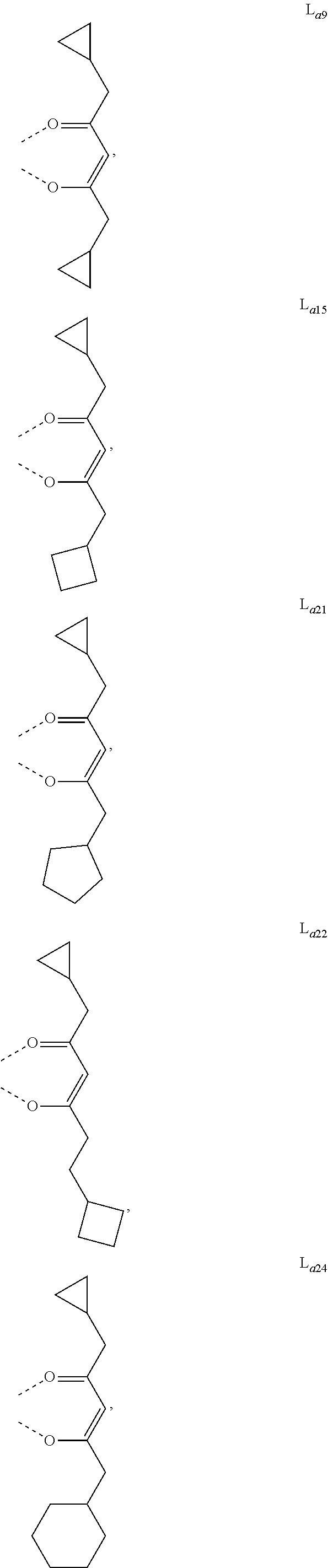
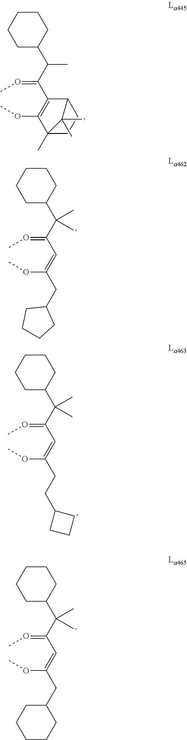
- R 3 is, at each occurrence identically or differently, selected from a substituted or unsubstituted cycloalkyl group having 3 to 6 ring carbon atoms.
- R 3 is, at each occurrence identically or differently, selected from cyclopropyl, cyclobutyl, cyclopentyl, or cyclohexyl.
- y1 is 1, y2 is 0, and y3 is 0; y1 is 1, y2 is 1, and y3 is 0; y1 is 0, y2 is 0, and y3 is 1; y1 is 2, y2 is 0, and y3 is 0; y1 is 2, y2 is 1, and y3 is 0; or y1 is 2, y2 is 2, and y3 is 0.
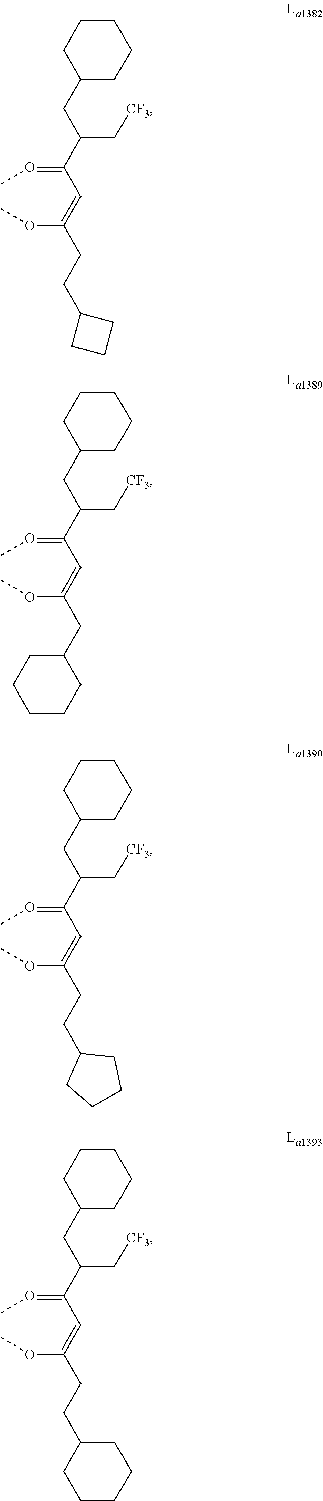
- L a is, at each occurrence identically or differently, selected from the group consisting of L a1 to L a1430 , wherein the specific structures of L a1 to L a1430 are referred to claim 12 .
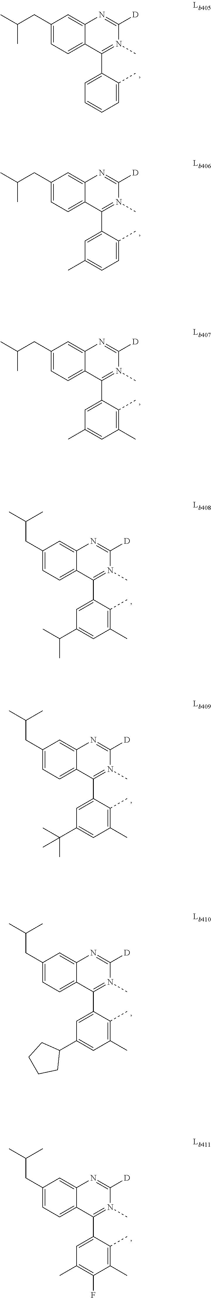
- L b is, at each occurrence identically or differently, selected from the group consisting of L b1 to L b531 , wherein the specific structures of L b1 to L b531 are referred to claim 13 .
- hydrogen in L b1 to L b531 may be partially or fully substituted with deuterium.
- the metal complex is selected from the group consisting of Metal complex 1 to Metal complex 180, wherein Metal complex 1 to Metal complex 180 each have a structure of Ir(L a )(L b ) 2 , wherein two L b are identical, and the specific structures of Metal complex 1 to Metal complex 180 are referred to claim 14 .
- the metal complex is selected from the group consisting of Metal complex 181 to Metal complex 205, wherein Metal complex 181 to Metal complex 205 each have a structure of Ir(L a )(L b ) 2 , wherein two L b are different, and the specific structures of Metal complex 181 to Metal complex 205 are referred to claim 14 .
- Halogen or halide—as used herein includes fluorine, chlorine, bromine, and iodine.
- Alkyl contemplates both straight and branched chain alkyl groups.
- alkyl group include methyl group, ethyl group, propyl group, isopropyl group, n-butyl group, s-butyl group, isobutyl group, t-butyl group, n-pentyl group, n-hexyl group, n-heptyl group, n-octyl group, n-nonyl group, n-decyl group, n-undecyl group, n-dodecyl group, n-tridecyl group, n-tetradecyl group, n-pentadecyl group, n-hexadecyl group, n-heptadecyl group, n-octadecyl group, neopentyl group, 1-methylpentyl group, 2-methylpentyl group, 1-pent
- alkyl group may be optionally substituted.
- the carbons in the alkyl chain can be replaced by other hetero atoms.
- preferred are methyl group, ethyl group, propyl group, isopropyl group, n-butyl group, s-butyl group, isobutyl group, t-butyl group, n-pentyl group, and neopentyl group.
- Preferred cycloalkyl groups are those containing 4 to 10 ring carbon atoms and includes cyclobutyl, cyclopentyl, cyclohexyl, 4-methylcyclohexyl, 4,4-dimethylcylcohexyl, 1-adamantyl, 2-adamantyl, 1-norbornyl, 2-norbornyl and the like. Additionally, the cycloalkyl group may be optionally substituted. The carbons in the ring can be replaced by other hetero atoms.
- Preferred alkenyl groups are those containing 2 to 15 carbon atoms.
- Examples of the alkenyl group include vinyl group, allyl group, 1-butenyl group, 2-butenyl group, 3-butenyl group, 1,3-butandienyl group, 1-methylvinyl group, styryl group, 2,2-diphenylvinyl group, 1,2-diphenylvinyl group, 1-methylallyl group, 1,1-dimethylallyl group, 2-methylallyl group, 1-phenylallyl group, 2-phenylallyl group, 3-phenylallyl group, 3,3-diphenylallyl group, 1,2-dimethylallyl group, 1-phenyl1-butenyl group, and 3-phenyl-1-butenyl group.
- the alkenyl group may be optionally substituted.
- Aryl or aromatic group—as used herein includes noncondensed and condensed systems.
- Preferred aryl groups are those containing six to sixty carbon atoms, preferably six to twenty carbon atoms, more preferably six to twelve carbon atoms.
- Examples of the aryl group include phenyl, biphenyl, terphenyl, triphenylene, tetraphenylene, naphthalene, anthracene, phenalene, phenanthrene, fluorene, pyrene, chrysene, perylene, and azulene, preferably phenyl, biphenyl, terphenyl, triphenylene, fluorene, and naphthalene.
- the aryl group may be optionally substituted.
- the non-condensed aryl group include phenyl group, biphenyl-2-yl group, biphenyl-3-yl group, biphenyl-4-yl group, p-terphenyl-4-yl group, p-terphenyl-3-yl group, p-terphenyl-2-yl group, m-terphenyl-4-yl group, m-terphenyl-3-yl group, m-terphenyl-2-yl group, o-tolyl group, m-tolyl group, p-tolyl group, p-t-butylphenyl group, p-(2-phenylpropyl)phenyl group, 4′-methylbiphenylyl group, 4′′-t-butyl p-terphenyl-4-yl group, o-cumenyl group, m-cumenyl group, p-cumenyl group,
- Heterocyclic group or heterocycle—as used herein includes aromatic and non-aromatic cyclic groups. Hetero-aromatic also means heteroaryl. Preferred non-aromatic heterocyclic groups are those containing 3 to 7 ring atoms which include at least one hetero atom such as nitrogen, oxygen, and sulfur. The heterocyclic group can also be an aromatic heterocyclic group having at least one heteroatom selected from nitrogen atom, oxygen atom, sulfur atom, and selenium atom.
- Heteroaryl—as used herein includes noncondensed and condensed hetero-aromatic groups that may include from one to five heteroatoms.
- Preferred heteroaryl groups are those containing three to thirty carbon atoms, preferably three to twenty carbon atoms, more preferably three to twelve carbon atoms.
- Suitable heteroaryl groups include dibenzothiophene, dibenzofuran, dibenzoselenophene, furan, thiophene, benzofuran, benzothiophene, benzoselenophene, carbazole, indolocarbazole, pyridylindole, pyrrolodipyridine, pyrazole, imidazole, triazole, oxazole, thiazole, oxadiazole, oxatriazole, dioxazole, thiadiazole, pyridine, pyridazine, pyrimidine, pyrazine, triazine, oxazine, oxathiazine, oxadiazine, indole, benzimidazole, indazole, indoxazine, benzoxazole, benzisoxazole, benzothiazole, quinoline, isoquinoline, cinnoline, qui
- Alkoxy—it is represented by —O-Alkyl. Examples and preferred examples thereof are the same as those described above. Examples of the alkoxy group having 1 to 20 carbon atoms, preferably 1 to 6 carbon atoms include methoxy group, ethoxy group, propoxy group, butoxy group, pentyloxy group, and hexyloxy group. The alkoxy group having 3 or more carbon atoms may be linear, cyclic or branched.
- Aryloxy—it is represented by —O-Aryl or —O-heteroaryl. Examples and preferred examples thereof are the same as those described above. Examples of the aryloxy group having 6 to 40 carbon atoms include phenoxy group and biphenyloxy group.
- benzyl group preferred are benzyl group, p-cyanobenzyl group, m-cyanobenzyl group, o-cyanobenzyl group, 1-phenylethyl group, 2-phenylethyl group, 1-phenylisopropyl group, and 2-phenylisopropyl group.
- aza in azadibenzofuran, aza-dibenzothiophene, etc. means that one or more of the C—H groups in the respective aromatic fragment are replaced by a nitrogen atom.
- azatriphenylene encompasses dibenzo[f,h]quinoxaline, dibenzo[f,h]quinoline and other analogues with two or more nitrogens in the ring system.
- multiple substitutions refer to a range that includes a double substitution, up to the maximum available substitutions.
- a substitution in the compounds mentioned in the present disclosure represents multiple substitutions (including di, tri, tetra substitutions etc.), that means the substituent may exist at a plurality of available substitution positions on its linking structure, the substituents present at a plurality of available substitution positions may be the same structure or different structures.
- the defined range of the number of atoms in a group refers to that the number of atoms in the group includes each integer within the given numerical range, where when referring to a substituted or unsubstituted group having a defined numerical range of carbon atoms or a substituted or unsubstituted group having a defined numerical range of ring atoms, the “defined numerical range” of atoms refers to the selectable range of the number of carbon atoms or ring atoms when the group is unsubstituted.
- a substituted or unsubstituted alkyl group having 1 to 20 carbon atoms it means that the alkyl group has 1 to 20 carbon atoms when unsubstituted.
- a substituted or unsubstituted cycloalkyl group having 3 to 20 ring carbon atoms it means that the cycloalkyl group has 3 to 20 ring carbon atoms when unsubstituted.
- adjacent substituents in the compounds cannot connect to form a ring unless otherwise explicitly defined, for example, adjacent substituents can be optionally joined to form a ring.
- adjacent substituents can be optionally joined to form a ring, including both the case where adjacent substituents can be joined to form a ring, and the case where adjacent substituents are not joined to form a ring.
- the ring formed may be monocyclic or polycyclic, as well as alicyclic, heteroalicyclic, aromatic or heteroaromatic.
- adjacent substituents may refer to substituents bonded to the same atom, substituents bonded to carbon atoms which are directly bonded to each other, or substituents bonded to carbon atoms which are more distant from each other.
- adjacent substituents refer to substituents bonded to the same carbon atom and substituents bonded to carbon atoms which are directly bonded to each other.
- adjacent substituents can be optionally joined to form a ring is also intended to mean that two substituents bonded to the same carbon atom are joined to each other via a chemical bond to form a ring, which can be exemplified by the following formula:
- adjacent substituents can be optionally joined to form a ring is also intended to mean that two substituents bonded to carbon atoms which are directly bonded to each other are joined to each other via a chemical bond to form a ring, which can be exemplified by the following formula:
- adjacent substituents can be optionally joined to form a ring is also intended to mean that, in the case where one of the two substituents bonded to carbon atoms which are directly bonded to each other represents hydrogen, the second substituent is bonded at a position at which the hydrogen atom is bonded, thereby forming a ring.
- This is exemplified by the following formula:
- the present disclosure further provides a compound formulation including any one of the metal complexes described above.
- the metal complex having the structure of M(L a ) m (L b ) n provided by the present disclosure may be combined with other components to obtain a compound formulation, and such combination can be used together.
- the present disclosure further provides an electroluminescent device including an anode, a cathode, and an organic layer disposed between the anode and the cathode, wherein the organic layer includes the metal complex described in the first object.
- the organic layer is a light-emitting layer and the metal complex is a light-emitting material.
- the electroluminescent device emits red light.
- the electroluminescent device emits white light.
- the light-emitting layer further includes at least one host material.
- the metal complex is doped as a doped material in the light-emitting layer at a weight percentage of 1 ⁇ to 20%, for example, 2 ⁇ , 3 ⁇ , 5 ⁇ , 8 ⁇ , 1%, 2%, 3%, 5%, 8%, 12%, 15%, 18%, or the like.
- the light-emitting layer further includes at least one host material; wherein the at least one host material comprises at least one chemical group selected from the group consisting of: benzene, pyridine, pyrimidine, triazine, carbazole, azacarbazole, indolocarbazole, dibenzothiophene, aza-dibenzothiophene, dibenzofuran, azadibenzofuran, dibenzoselenophene, triphenylene, azatriphenylene, fluorene, silafluorene, naphthalene, quinoline, isoquinoline, quinazoline, quinoxaline, phenanthrene, azaphenanthrene, and combinations thereof.
- the at least one host material comprises at least one chemical group selected from the group consisting of: benzene, pyridine, pyrimidine, triazine, carbazole, azacarbazole, indolocarbazole, dibenzothiophene
- FIG. 1 schematically shows an organic light emitting device 100 without limitation. The figures are not necessarily drawn to scale. Some of the layers in the figures can also be omitted as needed.
- Device 100 may include a substrate 101 , an anode 110 , a hole injection layer 120 , a hole transport layer 130 , an electron blocking layer 140 , an emissive layer 150 , a hole blocking layer 160 , an electron transport layer 170 , an electron injection layer 180 and a cathode 190 .
- Device 100 may be fabricated by depositing the layers described in order. The properties and functions of these various layers, as well as example materials, are described in more detail in U.S. Pat. No. 7,279,704 at cols. 6-10, the contents of which are incorporated by reference herein in its entirety.
- each of these layers are available.
- a flexible and transparent substrate-anode combination is disclosed in U.S. Pat. No. 5,844,363, which is incorporated by reference herein in its entirety.
- An example of a p-doped hole transport layer is m-MTDATA doped with F 4 -TCNQ at a molar ratio of 50:1, as disclosed in U.S. Patent Application Publication No. 2003/0230980, which is incorporated by reference herein in its entirety.
- host materials are disclosed in U.S. Pat. No. 6,303,238 to Thompson et al., which is incorporated by reference herein in its entirety.
- An example of an n-doped electron transport layer is BPhen doped with Li at a molar ratio of 1:1, as disclosed in U.S. Patent Application Publication No. 2003/0230980, which is incorporated by reference herein in its entirety.
- the theory and use of blocking layers are described in more detail in U.S. Pat. No. 6,097,147 and U.S. Patent Application Publication No.
- Functional OLEDs may be achieved by combining the various layers described in different ways, or layers may be omitted entirely. It may also include other layers not specifically described. Within each layer, a single material or a mixture of multiple materials can be used to achieve optimum performance. Any functional layer may include several sublayers. For example, the emissive layer may have two layers of different emitting materials to achieve desired emission spectrum.
- an OLED may be described as having an “organic layer” disposed between a cathode and an anode.
- This organic layer may comprise a single layer or multiple layers.
- FIG. 2 schematically shows an organic light emitting device 200 without limitation.
- FIG. 2 differs from FIG. 1 in that the organic light emitting device include a barrier layer 102 , which is above the cathode 190 , to protect it from harmful species from the environment such as moisture and oxygen.
- a barrier layer 102 which is above the cathode 190 , to protect it from harmful species from the environment such as moisture and oxygen.
- Any material that can provide the barrier function can be used as the barrier layer such as glass or organic-inorganic hybrid layers.
- the barrier layer should be placed directly or indirectly outside of the OLED device. Multilayer thin film encapsulation was described in U.S. Pat. No. 7,968,146, which is incorporated by reference herein in its entirety.
- Devices fabricated in accordance with embodiments of the present disclosure can be incorporated into a wide variety of consumer products that have one or more of the electronic component modules (or units) incorporated therein.
- Some examples of such consumer products include flat panel displays, monitors, medical monitors, televisions, billboards, lights for interior or exterior illumination and/or signaling, heads-up displays, fully or partially transparent displays, flexible displays, smart phones, tablets, phablets, wearable devices, smart watches, laptop computers, digital cameras, camcorders, viewfinders, micro-displays, 3-D displays, vehicles displays, and vehicle tail lights.
- top means furthest away from the substrate, while “bottom” means closest to the substrate.
- first layer is described as “disposed over” a second layer, the first layer is disposed further away from the substrate. There may be other layers between the first and second layers, unless it is specified that the first layer is “in contact with” the second layer.
- a cathode may be described as “disposed over” an anode, even though there are various organic layers in between.
- solution processible means capable of being dissolved, dispersed, or transported in and/or deposited from a liquid medium, either in solution or suspension form.
- a ligand may be referred to as “photoactive” when it is believed that the ligand directly contributes to the photoactive properties of an emissive material.
- a ligand may be referred to as “ancillary” when it is believed that the ligand does not contribute to the photoactive properties of an emissive material, although an ancillary ligand may alter the properties of a photoactive ligand.
- IQE internal quantum efficiency
- E-type delayed fluorescence does not rely on the collision of two triplets, but rather on the transition between the triplet states and the singlet excited states.
- Compounds that are capable of generating E-type delayed fluorescence are required to have very small singlet-triplet gaps to convert between energy states.
- Thermal energy can activate the transition from the triplet state back to the singlet state.
- This type of delayed fluorescence is also known as thermally activated delayed fluorescence (TADF).
- TADF thermally activated delayed fluorescence
- a distinctive feature of TADF is that the delayed component increases as temperature rises. If the reverse intersystem crossing rate is fast enough to minimize the non-radiative decay from the triplet state, the fraction of back populated singlet excited states can potentially reach 75%. The total singlet fraction can be 100%, far exceeding 25% of the spin statistics limit for electrically generated excitons.
- E-type delayed fluorescence characteristics can be found in an exciplex system or in a single compound. Without being bound by theory, it is believed that E-type delayed fluorescence requires the luminescent material to have a small singlet-triplet energy gap ( ⁇ E S-T ).
- Organic, non-metal containing, donor-acceptor luminescent materials may be able to achieve this.
- the emission in these materials is generally characterized as a donor-acceptor charge-transfer (CT) type emission.
- CT charge-transfer
- the spatial separation of the HOMO and LUMO in these donor-acceptor type compounds generally results in small ⁇ E S-T .
- These states may involve CT states.
- donor-acceptor luminescent materials are constructed by connecting an electron donor moiety such as amino- or carbazole-derivatives and an electron acceptor moiety such as N-containing six-membered aromatic rings.
- the materials described in the present disclosure for a particular layer in an organic light emitting device can be used in combination with various other materials present in the device.
- the combinations of these materials are described in more detail in U.S. Pat. App. No. 20160359122 at paragraphs 0132-0161, which is incorporated by reference herein in its entirety.
- the materials described or referred to the disclosure are non-limiting examples of materials that may be useful in combination with the compounds disclosed herein, and one of skill in the art can readily consult the literature to identify other materials that may be useful in combination.
- the materials described herein as useful for a particular layer in an organic light emitting device may be used in combination with a variety of other materials present in the device.
- dopants disclosed herein may be used in combination with a wide variety of hosts, transport layers, blocking layers, injection layers, electrodes and other layers that may be present.
- the combination of these materials is described in detail in paragraphs 0080-0101 of U.S. Pat. App. No. 2015/0349273, which is incorporated by reference herein in its entirety.
- the materials described or referred to the disclosure are non-limiting examples of materials that may be useful in combination with the compounds disclosed herein, and one of skill in the art can readily consult the literature to identify other materials that may be useful in combination.
- the present disclosure further provides a use of the electroluminescent device described above, where the electroluminescent device is applied to an electronic device, an electronic element module, an organic light-emitting device, or a lighting panel.
- the method for preparing a compound in the present disclosure is not limited herein. Typically, the following compounds are used as examples without limitations, and synthesis routes and preparation methods thereof are described below.
- the reaction solution was filtered through Celite, the filter cake was washed with an appropriate amount of EtOH, and the crude product was dissolved with DCM into a 250 mL eggplant-shaped flask.
- EtOH about 20 mL was added thereto, and DCM was removed through rotary evaporation at normal temperature.
- the solids were precipitated, filtered, and washed with EtOH to give the product Metal complex 126 (520 mg with a yield of 46%).
- the product was confirmed as the target product with a molecular weight of 1032.5.
- reaction solution was cooled to 0° C., and 1 M/L HCl was slowly added to quench the reaction.
- the reaction solution was diluted with water, and allowed to stand still. Layers were separated, and then were extracted with dichloromethane. The organic phases were combined and dried through rotary evaporation to give 2-cyclobutyl-N-methoxy-N-methylacetamide (Intermediate 7) as a light yellow liquid (6.8 g, 99%).
- the crude product was directly used in the next step without purification.
- This example provides an electroluminescent device which is prepared by a method described below.
- a glass substrate having an Indium Tin Oxide (ITO) anode with a thickness of 120 nm was cleaned and then treated with oxygen plasma and UV ozone. After the treatment, the substrate was dried in a glovebox to remove moisture.
- the substrate was mounted on a substrate holder and placed in a vacuum chamber.
- Organic layers specified below were sequentially deposited through vacuum thermal evaporation on the ITO anode at a rate of 0.2 to 2 Angstroms per second at a vacuum degree of about 10 ⁇ 8 torr.
- Compound HI was used as a hole injection layer (HIL) with a thickness of 100 ⁇ .
- Compound HT was used as a hole transporting layer (HTL) with a thickness of 400 ⁇ .
- Compound EB was used as an electron blocking layer (EBL) with a thickness of 50 ⁇ .
- Metal complex 54 of the present disclosure was doped in a host compound RH to be used as an emissive layer (EML) with a thickness of 400 ⁇ .
- Compound HB was used as a hole blocking layer (HBL) with a thickness of 50 ⁇ .
- HBL hole blocking layer
- a mixture of Compound ET and 8-hydroxyquinolinolato-lithium (Liq) was deposited as an electron transporting layer (ETL) with a thickness of 350 ⁇ .
- Liq with a thickness of 1 nm was deposited as an electron injection layer
- Al with a thickness of 120 nm was deposited as a cathode.
- the device was transferred back to the glovebox and encapsulated with a glass lid and a moisture getter to complete the device.
- the preparation method in Device Example 4 was the same as that in Device Example 1, except that Metal complex 54 of the present disclosure in Device Example 1 was substituted with Metal complex 11 of the present disclosure.
- the preparation method in Device Comparative Example 1 was the same as that in Device Example 1, except that Metal complex 54 of the present disclosure in Device Example 1 was substituted with Compound RD.
- the structures and thicknesses of layers of the devices are shown in the following table.
- the layers using more than one material were obtained by doping different compounds at weight proportions as recorded.
- Comparative Example 1 Since Comparative Example 1 has best performance when the doping proportion is 3%, the present disclosure performs comparisons and analyzes at a doping proportion of 3%. However, the present disclosure is not limited to a doping proportion of 3%.
- ⁇ max of the compounds can be maintained basically unchanged by changing cycloalkyl substituents on a dione ancillary ligand and the number of carbon atoms between a cycloalkyl group and a carbonyl group, so as to fine-tune the light-emitting color of the devices.
- the examples Compared with the comparative example having the full width at half maximum of 54.7 nm, the examples have full width at half maximums within the range of 52.1 nm to 54.3 nm. It can be seen that the full width at half maximum (FWHM) of the examples is narrowed to different degrees, such that the devices using the metal complexes of the present disclosure have the more saturated light-emitting color.
- the current efficiency of the comparative example is 19.05 cd/A. According to the data in the table, the current efficiency of all the four examples is greater than 19.05 cd/A. Meanwhile, the external quantum efficiency of all the four examples is greater than that of the comparative example which is 23.61%. Therefore, the current efficiency (CE) and the external quantum efficiency (EQE) of the device using the metal complex of the present disclosure are improved compared with those of Comparative Example 1, embodying the uniqueness and importance of the present disclosure.
Landscapes
- Chemical & Material Sciences (AREA)
- Organic Chemistry (AREA)
- Engineering & Computer Science (AREA)
- Materials Engineering (AREA)
- Crystallography & Structural Chemistry (AREA)
- Inorganic Chemistry (AREA)
- Physics & Mathematics (AREA)
- Spectroscopy & Molecular Physics (AREA)
- Optics & Photonics (AREA)
- Electroluminescent Light Sources (AREA)
Abstract
Description

in which the C{circumflex over ( )}N ligand is a 2-phenylisoquinoline-based structure and the dione ligand is a trideuterated ancillary ligand. Although the introduction of an isotope atom into the dione-based ancillary ligand improves the performance of the organic light-emitting material, it is difficult to ensure the number and positions of isotopes introduced during preparation, which makes it difficult to prepare such a material. In addition, application of a dione ligand without deuterium substitutions has not been disclosed or taught.

in which the ring B is an aromatic ring fused to the benzene ring. The metal complex includes an ancillary ligand having a structure of

in which R1 and R2 are substituted or unsubstituted alkyl or substituted or unsubstituted cycloalkyl. Although the introduction of cycloalkyl-substituted alkylene into a dione-based ancillary ligand improves the performance of an organic light-emitting material, the disclosed C{circumflex over ( )}N ligand has to contain a fused aromatic ring structure formed by fusing a benzene ring to the ring B. The use of a C{circumflex over ( )}N ligand having a monocyclic (hetero) aromatic ring structure, such as a benzene ring structure, in combination with a dione-based ancillary ligand has not been disclosed or taught.

where at least two consecutive of Z1 to Z4 are C and are fused to a structure of

Apparently, the disclosed complex has to include a C{circumflex over ( )}N ligand having a 6-membered-fused-5-membered aromatic heterocyclic ring structure. The use of a C{circumflex over ( )}N ligand having a 6-membered-fused-6-membered aromatic heterocyclic ring structure, such as a quinoline ring or an isoquinoline ring, in combination with a dione-based ancillary ligand has not been disclosed or taught. The metal complexes formed by such ligands included in this patent have a relatively large full width at half maximum and a relatively high voltage, which limits the application of materials.

Apparently, the complex has to include a ligand having a phenanthrene or azaphenanthrene structure. The use of a C{circumflex over ( )}N ligand having a monocyclic (hetero) aromatic ring structure, such as a benzene ring structure, in combination with a dione ancillary ligand has not been disclosed or taught. Such structures have too low light-emitting efficiency despite a relatively long service life.

in which the ring A is a five- or six-membered carbocyclic or heterocyclic ring and Y is a single bond, O, S, Se, NR, CRR′, SiRR′, or GeRR′. Apparently, the disclosed complex has to include a ligand having a multi-fused ring structure such as acenaphthylene, heteroacenaphthylene, phenalene, heterophenalene, or similar structures. The use of a C{circumflex over ( )}N ligand having a 6-membered-fused-6-membered aromatic heterocyclic ring structure, such as a quinoline ring or an isoquinoline ring, in combination with a dione-based ancillary ligand has not been disclosed or taught. The metal complexes included in this patent belong to infrared luminescent materials, which limits the application of such materials.
-
- wherein, the metal M is a metal whose relative atomic mass is greater than 40, La and Lb are the first ligand and the second ligand of the metal complex, and La and Lb can be optionally joined to form a multidentate ligand;
- m is 1 or 2, n is 1 or 2, and m+n equals an oxidation state of the metal M;
- when m is 2, both of La are identical or different; when n is 2, both of Lb are identical or different;
- the first ligand La has a structure represented by Formula 1:

-
- wherein,
- x1=0, 1, 2, or 3, y1=0, 1, 2, or 3, and x1+y1=3;
- x2=0, 1, 2, or 3, y2=0, 1, 2, or 3, and x2+y2=3;
- x3=0 or 1, y3=0 or 1, and x3+y3=1; and
- y1+y2+y3≥1;
- R1 is, at each occurrence identically or differently, selected from hydrogen, deuterium, halogen, a substituted or unsubstituted alkyl group having 1 to 20 carbon atoms, a substituted or unsubstituted cycloalkyl group having 3 to 20 ring carbon atoms, a substituted or unsubstituted heteroalkyl group having 1 to 20 carbon atoms, a substituted or unsubstituted arylalkyl group having 7 to 30 carbon atoms, a substituted or unsubstituted alkoxy group having 1 to 20 carbon atoms, a substituted or unsubstituted aryloxy group having 6 to 30 carbon atoms, a substituted or unsubstituted alkenyl group having 2 to 20 carbon atoms, a substituted or unsubstituted aryl group having 6 to 30 carbon atoms, a substituted or unsubstituted heteroaryl group having 3 to 30 carbon atoms, a substituted or unsubstituted alkylsilyl group having 3 to 20 carbon atoms, a substituted or unsubstituted arylsilyl group having 6 to 20 carbon atoms, a substituted or unsubstituted amino group having 0 to 20 carbon atoms, an acyl group, a carbonyl group, a carboxylic acid group, an ester group, a cyano group, an isocyano group, a sulfanyl group, a sulfinyl group, a sulfonyl group, a phosphino group, or a combination thereof,
- R2 is, at each occurrence identically or differently, selected from -L-R3, wherein L is, at each occurrence identically or differently, selected from a single bond, a substituted or unsubstituted alkylene group having 1 to 20 carbon atoms, a substituted or unsubstituted cycloalkylene group having 3 to 20 ring carbon atoms, a substituted or unsubstituted heteroalkylene group having 1 to 20 carbon atoms, a substituted or unsubstituted arylene group having 6 to 30 carbon atoms, or a substituted or unsubstituted heteroarylene group having 3 to 30 carbon atoms; and R3 represents substituted or unsubstituted cycloalkyl having 3 to 20 ring carbon atoms;
- R4 is, at each occurrence identically or differently, selected from hydrogen, halogen, a substituted or unsubstituted alkyl group having 1 to 20 carbon atoms, a substituted or unsubstituted cycloalkyl group having 3 to 20 ring carbon atoms, a substituted or unsubstituted heteroalkyl group having 1 to 20 carbon atoms, a substituted or unsubstituted arylalkyl group having 7 to 30 carbon atoms, a substituted or unsubstituted alkoxy group having 1 to 20 carbon atoms, a substituted or unsubstituted aryloxy group having 6 to 30 carbon atoms, a substituted or unsubstituted alkenyl group having 2 to 20 carbon atoms, a substituted or unsubstituted aryl group having 6 to 30 carbon atoms, a substituted or unsubstituted heteroaryl group having 3 to 30 carbon atoms, a substituted or unsubstituted alkylsilyl group having 3 to 20 carbon atoms, a substituted or unsubstituted arylsilyl group having 6 to 20 carbon atoms, a substituted or unsubstituted amino group having 0 to 20 carbon atoms, an acyl group, a carbonyl group, a carboxylic acid group, an ester group, a cyano group, an isocyano group, a sulfanyl group, a sulfinyl group, a sulfonyl group, a phosphino group, or a combination thereof,
- wherein adjacent substituents R1, R4 can be optionally joined to form a ring;
- Lb is, at each occurrence identically or differently, selected from a structure represented by Formula 2, Formula 3, or Formula 4:
- wherein,

-
- wherein, X1 and X2 are, at each occurrence identically or differently, selected from CRx or N; and X3, X4, X5, and X6 are, at each occurrence identically or differently, selected from CRy or N; wherein adjacent substituents Rx can be optionally joined to form a ring, and adjacent substituents Ry can be optionally joined to form a ring;
- wherein, the ring Ar is a five-membered aromatic ring, a six-membered aromatic ring, a five-membered heteroaromatic ring, or a six-membered heteroaromatic ring;
- wherein, RAr represents mono-substitution, multi-substitution, or no substitution;
- Rx, Ry, and RAr are, at each occurrence identically or differently, selected from hydrogen, deuterium, halogen, a substituted or unsubstituted alkyl group having 1 to 20 carbon atoms, a substituted or unsubstituted cycloalkyl group having 3 to 20 ring carbon atoms, a substituted or unsubstituted heteroalkyl group having 1 to 20 carbon atoms, a substituted or unsubstituted arylalkyl group having 7 to 30 carbon atoms, a substituted or unsubstituted alkoxy group having 1 to 20 carbon atoms, a substituted or unsubstituted aryloxy group having 6 to 30 carbon atoms, a substituted or unsubstituted alkenyl group having 2 to 20 carbon atoms, a substituted or unsubstituted aryl group having 6 to 30 carbon atoms, a substituted or unsubstituted heteroaryl group having 3 to 30 carbon atoms, a substituted or unsubstituted alkylsilyl group having 3 to 20 carbon atoms, a substituted or unsubstituted arylsilyl group having 6 to 20 carbon atoms, a substituted or unsubstituted amino group having 0 to 20 carbon atoms, an acyl group, a carbonyl group, a carboxylic acid group, an ester group, a cyano group, an isocyano group, a sulfanyl group, a sulfinyl group, a sulfonyl group, a phosphino group, or a combination thereof, and
- wherein when a substituent RAr is selected from a substituted or unsubstituted alkyl group having 1 to 20 carbon atoms, a substituted or unsubstituted cycloalkyl group having 3 to 20 ring carbon atoms, a substituted or unsubstituted heteroalkyl group having 1 to 20 carbon atoms, a substituted or unsubstituted arylalkyl group having 7 to 30 carbon atoms, a substituted or unsubstituted alkoxy group having 1 to 20 carbon atoms, a substituted or unsubstituted amino group having 0 to 20 carbon atoms, a sulfanyl group, or a substituted or unsubstituted aryloxy group having 6 to 30 carbon atoms, adjacent substituents RAr can be optionally joined to form a ring.
-
- wherein, the metal M is a metal whose relative atomic mass is greater than 40, La and Lb are the first ligand and the second ligand of the metal complex, and La and Lb can be optionally joined to form a multidentate ligand;
- m is 1 or 2, n is 1 or 2, and m+n equals an oxidation state of the metal M;
- when m is 2, both of La are identical or different; when n is 2, both of Lb are identical or different;
- the first ligand La has a structure represented by Formula 1:

-
- wherein,
- x1=0, 1, 2, or 3, y1=0, 1, 2, or 3, and x1+y1=3;
- x2=0, 1, 2, or 3, y2=0, 1, 2, or 3, and x2+y2=3;
- x3=0 or 1, y3=0 or 1, and x3+y3=1; and
- y1+y2+y3≥1;
- R1 is, at each occurrence identically or differently, selected from hydrogen, deuterium, halogen, a substituted or unsubstituted alkyl group having 1 to 20 carbon atoms, a substituted or unsubstituted cycloalkyl group having 3 to 20 ring carbon atoms, a substituted or unsubstituted heteroalkyl group having 1 to 20 carbon atoms, a substituted or unsubstituted arylalkyl group having 7 to 30 carbon atoms, a substituted or unsubstituted alkoxy group having 1 to 20 carbon atoms, a substituted or unsubstituted aryloxy group having 6 to 30 carbon atoms, a substituted or unsubstituted alkenyl group having 2 to 20 carbon atoms, a substituted or unsubstituted aryl group having 6 to 30 carbon atoms, a substituted or unsubstituted heteroaryl group having 3 to 30 carbon atoms, a substituted or unsubstituted alkylsilyl group having 3 to 20 carbon atoms, a substituted or unsubstituted arylsilyl group having 6 to 20 carbon atoms, a substituted or unsubstituted amino group having 0 to 20 carbon atoms, an acyl group, a carbonyl group, a carboxylic acid group, an ester group, a cyano group, an isocyano group, a sulfanyl group, a sulfinyl group, a sulfonyl group, a phosphino group, or a combination thereof,
- R2 is, at each occurrence identically or differently, selected from -L-R3, wherein L is, at each occurrence identically or differently, selected from a single bond, a substituted or unsubstituted alkylene group having 1 to 20 carbon atoms, a substituted or unsubstituted cycloalkylene group having 3 to 20 ring carbon atoms, a substituted or unsubstituted heteroalkylene group having 1 to 20 carbon atoms, a substituted or unsubstituted arylene group having 6 to 30 carbon atoms, or a substituted or unsubstituted heteroarylene group having 3 to 30 carbon atoms; and R3 represents substituted or unsubstituted cycloalkyl having 3 to 20 ring carbon atoms;
- R4 is, at each occurrence identically or differently, selected from hydrogen, halogen, a substituted or unsubstituted alkyl group having 1 to 20 carbon atoms, a substituted or unsubstituted cycloalkyl group having 3 to 20 ring carbon atoms, a substituted or unsubstituted heteroalkyl group having 1 to 20 carbon atoms, a substituted or unsubstituted arylalkyl group having 7 to 30 carbon atoms, a substituted or unsubstituted alkoxy group having 1 to 20 carbon atoms, a substituted or unsubstituted aryloxy group having 6 to 30 carbon atoms, a substituted or unsubstituted alkenyl group having 2 to 20 carbon atoms, a substituted or unsubstituted aryl group having 6 to 30 carbon atoms, a substituted or unsubstituted heteroaryl group having 3 to 30 carbon atoms, a substituted or unsubstituted alkylsilyl group having 3 to 20 carbon atoms, a substituted or unsubstituted arylsilyl group having 6 to 20 carbon atoms, a substituted or unsubstituted amino group having 0 to 20 carbon atoms, an acyl group, a carbonyl group, a carboxylic acid group, an ester group, a cyano group, an isocyano group, a sulfanyl group, a sulfinyl group, a sulfonyl group, a phosphino group, or a combination thereof,
- wherein adjacent substituents R1, R4 can be optionally joined to form a ring;
- Lb is, at each occurrence identically or differently, selected from a structure represented by Formula 2, Formula 3, or Formula 4:
- wherein,

-
- wherein, X1 and X2 are, at each occurrence identically or differently, selected from CRx or N; and X3, X4, X5, and X6 are, at each occurrence identically or differently, selected from CRy or N; wherein adjacent substituents Rx can be optionally joined to form a ring, and adjacent substituents Ry can be optionally joined to form a ring;
- wherein, the ring Ar is a five-membered aromatic ring, a six-membered aromatic ring, a five-membered heteroaromatic ring, or a six-membered heteroaromatic ring;
- wherein, RAr represents mono-substitution, multi-substitution, or no substitution;
- Rx, Ry, and RAr are, at each occurrence identically or differently, selected from hydrogen, deuterium, halogen, a substituted or unsubstituted alkyl group having 1 to 20 carbon atoms, a substituted or unsubstituted cycloalkyl group having 3 to 20 ring carbon atoms, a substituted or unsubstituted heteroalkyl group having 1 to 20 carbon atoms, a substituted or unsubstituted arylalkyl group having 7 to 30 carbon atoms, a substituted or unsubstituted alkoxy group having 1 to 20 carbon atoms, a substituted or unsubstituted aryloxy group having 6 to 30 carbon atoms, a substituted or unsubstituted alkenyl group having 2 to 20 carbon atoms, a substituted or unsubstituted aryl group having 6 to 30 carbon atoms, a substituted or unsubstituted heteroaryl group having 3 to 30 carbon atoms, a substituted or unsubstituted alkylsilyl group having 3 to 20 carbon atoms, a substituted or unsubstituted arylsilyl group having 6 to 20 carbon atoms, a substituted or unsubstituted amino group having 0 to 20 carbon atoms, an acyl group, a carbonyl group, a carboxylic acid group, an ester group, a cyano group, an isocyano group, a sulfanyl group, a sulfinyl group, a sulfonyl group, a phosphino group, or a combination thereof, and
- wherein when a substituent RAr is selected from a substituted or unsubstituted alkyl group having 1 to 20 carbon atoms, a substituted or unsubstituted cycloalkyl group having 3 to 20 ring carbon atoms, a substituted or unsubstituted heteroalkyl group having 1 to 20 carbon atoms, a substituted or unsubstituted arylalkyl group having 7 to 30 carbon atoms, a substituted or unsubstituted alkoxy group having 1 to 20 carbon atoms, a substituted or unsubstituted amino group having 0 to 20 carbon atoms, a sulfanyl group, or a substituted or unsubstituted aryloxy group having 6 to 30 carbon atoms, adjacent substituents RAr can be optionally joined to form a ring.


-
- wherein Rx and Ry are, at each occurrence identically or differently, selected from hydrogen, deuterium, halogen, a substituted or unsubstituted alkyl group having 1 to 20 carbon atoms, a substituted or unsubstituted cycloalkyl group having 3 to 20 ring carbon atoms, a substituted or unsubstituted alkylsilyl group having 3 to 20 carbon atoms, a substituted or unsubstituted arylsilyl group having 6 to 20 carbon atoms, a cyano group, or a combination thereof; and
- wherein RAr is, at each occurrence identically or differently, selected from hydrogen, deuterium, halogen, a substituted or unsubstituted alkyl group having 1 to 20 carbon atoms, a substituted or unsubstituted heteroalkyl group having 1 to 20 carbon atoms, a substituted or unsubstituted aryl group having 6 to 30 carbon atoms, or a combination thereof.

-
- wherein Rx and Ry are selected from hydrogen, deuterium, methyl, isopropyl, isobutyl, cyclopentyl, 4,4-dimethylcyclohexyl, 4,4-diethylcyclohexyl, 4-oxocyclohexyl, trimethylsilyl, dimethylisopropylsilyl, dimethylphenylsilyl, cyano, or a combination thereof; and at least one of Rx or Ry is not hydrogen; and
- wherein RAr is selected from hydrogen, deuterium, methyl, isopropyl, t-butyl, cyclopentyl, cyclohexyl, phenyl, or a combination thereof, and at least one RAr is not hydrogen.


| TABLE 1 |
| Device structures in device examples and a comparative example |
| Device No. | HIL | HTL | EBL | EML | HBL | ETL |
| Comparative | Compound | Compound | Compound | Compound | Compound | Compound |
| Example 1 | HI (100 Å) | HT (400 Å) | EB (50 Å) | RH: | HB (50 Å) | ET: Liq (40: |
| Compound | 60) (350 Å) | |||||
| RD (97: 3) | ||||||
| (400 Å) | ||||||
| Example 1 | Compound | Compound | Compound | Compound | Compound | Compound |
| HI (100 Å) | HT (400 Å) | EB (50 Å) | RH: Metal | HB (50 Å) | ET: Liq (40: | |
| complex 54 | 60) (350 Å) | |||||
| (97: 3) | ||||||
| (400 Å) | ||||||
| Example 2 | Compound | Compound | Compound | Compound | Compound | Compound |
| HI (100 Å) | HT (400 Å) | EB (50 Å) | RH: Metal | HB (50 Å) | ET: Liq (40: | |
| complex 126 | 60) (350 Å) | |||||
| (97: 3) | ||||||
| (400 Å) | ||||||
| Example 3 | Compound | Compound | Compound | Compound | Compound | Compound |
| HI (100 Å) | HT (400 Å) | EB (50 Å) | RH: Metal | HB (50 Å) | ET: Liq (40: | |
| complex 30 | 60) (350 Å) | |||||
| (97: 3) | ||||||
| (400 Å) | ||||||
| Example 4 | Compound | Compound | Compound | Compound | Compound | Compound |
| HI (100 Å) | HT (400 Å) | EB (50 Å) | RH: Metal | HB (50 Å) | ET: Liq (40: | |
| complex 11 | 60) (350 Å) | |||||
| (97: 3) | ||||||
| (400 Å) | ||||||


Performance Test:
| TABLE 2 |
| Device data |
| λmax | FWHM | CE | EQE | ||
| Device No. | CIE (x, y) | (nm) | (nm) | (cd/A) | (%) |
| Comparative | (0.684, 0.315) | 625 | 54.7 | 19.05 | 23.61 |
| Example 1 | |||||
| Example 1 | (0.682, 0.317) | 625 | 52.1 | 20.09 | 23.86 |
| (Metal | |||||
| complex 54) | |||||
| Example 2 | (0.683, 0.316) | 625 | 54.3 | 20.02 | 24.27 |
| (Metal | |||||
| complex 126) | |||||
| Example 3 | (0.683, 0.316) | 625 | 52.7 | 20.66 | 24.96 |
| (Metal | |||||
| complex 30) | |||||
| Example 4 | (0.684, 0.315) | 626 | 53.4 | 19.95 | 24.44 |
| (Metal | |||||
| complex 11) | |||||
Claims (26)


Applications Claiming Priority (2)
| Application Number | Priority Date | Filing Date | Title |
|---|---|---|---|
| CN202010048228.3A CN113121609B (en) | 2020-01-16 | 2020-01-16 | Metal complex, electroluminescent device comprising same and application of metal complex |
| CN202010048228.3 | 2020-01-16 |
Publications (2)
| Publication Number | Publication Date |
|---|---|
| US20220131093A1 US20220131093A1 (en) | 2022-04-28 |
| US12201014B2 true US12201014B2 (en) | 2025-01-14 |
Family
ID=76771952
Family Applications (1)
| Application Number | Title | Priority Date | Filing Date |
|---|---|---|---|
| US17/150,305 Active 2042-11-09 US12201014B2 (en) | 2020-01-16 | 2021-01-15 | Metal complex, electroluminescent device including the same, and use thereof |
Country Status (3)
| Country | Link |
|---|---|
| US (1) | US12201014B2 (en) |
| KR (1) | KR102706407B1 (en) |
| CN (1) | CN113121609B (en) |
Families Citing this family (7)
| Publication number | Priority date | Publication date | Assignee | Title |
|---|---|---|---|---|
| CN111909212B (en) | 2019-05-09 | 2023-12-26 | 北京夏禾科技有限公司 | An organic light-emitting material containing 6-silyl-substituted isoquinoline ligand |
| CN111909214B (en) | 2019-05-09 | 2024-03-29 | 北京夏禾科技有限公司 | Organic luminescent material containing 3-deuterium substituted isoquinoline ligand |
| CN111909213B (en) | 2019-05-09 | 2024-02-27 | 北京夏禾科技有限公司 | A metal complex containing three different ligands |
| CN112679548B (en) | 2019-10-18 | 2023-07-28 | 北京夏禾科技有限公司 | Organic light-emitting materials with auxiliary ligands of partially fluorine-substituted substituents |
| CN118084980A (en) | 2020-01-10 | 2024-05-28 | 北京夏禾科技有限公司 | Organic light-emitting materials |
| CN114891042B (en) * | 2022-05-18 | 2023-04-07 | 吉林奥来德光电材料股份有限公司 | Organic metal compound and application thereof, luminescent device and luminescent device |
| CN121673335A (en) * | 2026-02-09 | 2026-03-17 | 吉林奥来德光电材料股份有限公司 | Phosphorescent doped material, preparation method thereof and organic electroluminescent device |
Citations (103)
| Publication number | Priority date | Publication date | Assignee | Title |
|---|---|---|---|---|
| US5703436A (en) | 1994-12-13 | 1997-12-30 | The Trustees Of Princeton University | Transparent contacts for organic devices |
| US5707745A (en) | 1994-12-13 | 1998-01-13 | The Trustees Of Princeton University | Multicolor organic light emitting devices |
| JPH10158639A (en) | 1996-12-05 | 1998-06-16 | Mitsui Chem Inc | Electroluminescent element produced by using europium complex |
| US5844363A (en) | 1997-01-23 | 1998-12-01 | The Trustees Of Princeton Univ. | Vacuum deposited, non-polymeric flexible organic light emitting devices |
| US6097147A (en) | 1998-09-14 | 2000-08-01 | The Trustees Of Princeton University | Structure for high efficiency electroluminescent device |
| US6303238B1 (en) | 1997-12-01 | 2001-10-16 | The Trustees Of Princeton University | OLEDs doped with phosphorescent compounds |
| WO2002044189A1 (en) | 2000-11-30 | 2002-06-06 | Canon Kabushiki Kaisha | Luminescent element and display |
| US20030072964A1 (en) | 2001-10-17 | 2003-04-17 | Kwong Raymond C. | Phosphorescent compounds and devices comprising the same |
| US20030096138A1 (en) | 2001-11-07 | 2003-05-22 | Lecloux Daniel David | Electroluminescent iridium compounds having red-orange or red emission and devices made with such compounds |
| US20030230980A1 (en) | 2002-06-18 | 2003-12-18 | Forrest Stephen R | Very low voltage, high efficiency phosphorescent oled in a p-i-n structure |
| US20040174116A1 (en) | 2001-08-20 | 2004-09-09 | Lu Min-Hao Michael | Transparent electrodes |
| US20040241495A1 (en) | 2003-04-22 | 2004-12-02 | Raymond Kwong | Organic light emitting devices having reduced pixel shrinkage |
| US20060008671A1 (en) | 2004-07-07 | 2006-01-12 | Raymond Kwong | Electroluminescent efficiency |
| US20060008673A1 (en) | 2004-07-07 | 2006-01-12 | Raymond Kwong | Electroluminescent efficiency |
| KR20060097320A (en) | 2005-03-05 | 2006-09-14 | 주식회사 두산 | Novel Iridium Complexes and Organic Electroluminescent Devices Using the Same |
| US7279704B2 (en) | 2004-05-18 | 2007-10-09 | The University Of Southern California | Complexes with tridentate ligands |
| US20070259205A1 (en) | 2006-05-08 | 2007-11-08 | Ionkin Alex S | Electroluminescent bis-cyclometalled iridium compounds and devices made with such compounds |
| US20070278936A1 (en) | 2006-06-02 | 2007-12-06 | Norman Herron | Red emitter complexes of IR(III) and devices made with such compounds |
| US20080001515A1 (en) | 2006-07-03 | 2008-01-03 | Kabushiki Kaisha Toshiba | Fluorescent complex and lighting system using the same |
| US20080074033A1 (en) | 2006-06-14 | 2008-03-27 | Alex Sergey Ionkin | Electroluminescent iridium compounds with silylated, germanylated, and stannylated ligands, and devices made with such compounds |
| US20080261076A1 (en) | 2007-03-08 | 2008-10-23 | Universal Display Corporation | Phosphorescent materials |
| KR20090039464A (en) | 2007-10-18 | 2009-04-22 | 에스에프씨 주식회사 | Red phosphorescent compound and organic light emitting device using the same |
| US20100051869A1 (en) | 2006-07-28 | 2010-03-04 | General Electric Company | Organic iridium compositions and their use in electronic devices |
| US20100090591A1 (en) | 2008-09-16 | 2010-04-15 | Universal Display Corporation | Phosphorescent materials |
| US20100270916A1 (en) | 2009-04-28 | 2010-10-28 | Universal Display Corporation | Iridium complex with methyl-d3 substitution |
| US7968146B2 (en) | 2006-11-01 | 2011-06-28 | The Trustees Of Princeton University | Hybrid layers for use in coatings on electronic devices or other articles |
| KR20110077350A (en) | 2009-12-30 | 2011-07-07 | 엘지디스플레이 주식회사 | Red phosphorescent compound, organic electroluminescent device using same and manufacturing method thereof |
| US20120119190A1 (en) | 2010-11-11 | 2012-05-17 | Universal Display Corporation | Phosphorescent materials |
| US20120181511A1 (en) | 2011-01-13 | 2012-07-19 | Universal Display Corporation | 5-Substituted 2 Phenylquinoline Complexes Materials for Light Emitting Diode |
| US20120217868A1 (en) | 2011-02-24 | 2012-08-30 | Universal Display Corporation | Germanium-containing red emitter materials for organic light emitting diode |
| US20130146848A1 (en) | 2011-12-09 | 2013-06-13 | Universal Display Corporation | Novel Organic Light Emitting Materials |
| CN103204880A (en) | 2012-11-12 | 2013-07-17 | 吉林奥来德光电材料股份有限公司 | Organophosphorus luminescence material, its preparation method, and organic electroluminescent device made through using it |
| KR20130110934A (en) | 2012-03-30 | 2013-10-10 | 에스에프씨 주식회사 | Organometallic compounds and organic light emitting diodes comprising the compounds |
| US20130299795A1 (en) | 2011-01-13 | 2013-11-14 | Universal Display Corporation | Materials for organic light emitting diode |
| US20130328019A1 (en) | 2012-06-06 | 2013-12-12 | Universal Display Corporation | Metal complex with three different ligands |
| US20140203265A1 (en) | 2010-01-20 | 2014-07-24 | Hitachi, Ltd. | Organic luminescent materials, coating solution using same for organic |
| US20150001472A1 (en) * | 2013-07-01 | 2015-01-01 | Universal Display Corporation | Ancillary ligands for organometallic complexes |
| US20150053939A1 (en) | 2013-08-20 | 2015-02-26 | Universal Display Corporation | Organic electroluminescent materials and devices |
| US20150171348A1 (en) | 2012-08-07 | 2015-06-18 | Merck Patent Gmbh | Metal Complexes |
| US20150188061A1 (en) | 2013-12-23 | 2015-07-02 | Universal Display Corporation | Organic electroluminescent materials and devices |
| US20150214494A1 (en) | 2014-01-30 | 2015-07-30 | Universal Display Corporation | Organic electroluminescent materials and devices |
| EP2907820A1 (en) | 2014-02-18 | 2015-08-19 | Universal Display Corporation | Organic electroluminescent materials and devices |
| US20150287933A1 (en) | 2014-04-02 | 2015-10-08 | Universal Display Corporation | Organic electroluminescent materials and devices |
| US20150295187A1 (en) | 2014-04-09 | 2015-10-15 | Universal Display Corporation | Organic electroluminescent materials and devices |
| EP2940098A1 (en) | 2014-05-02 | 2015-11-04 | Universal Display Corporation | Organic electroluminescent materials and devices |
| US20150349273A1 (en) | 2014-06-03 | 2015-12-03 | Universal Display Corporation | Organic electroluminescent materials and devices |
| US20150357587A1 (en) | 2013-01-17 | 2015-12-10 | Canon Kabushiki Kaisha | Organic light-emitting element |
| US20150364701A1 (en) | 2013-01-21 | 2015-12-17 | Canon Kabushiki Kaisha | Organometallic complex and organic light-emitting element using the complex |
| US20160028023A1 (en) | 2014-07-22 | 2016-01-28 | Universal Display Corporation | Organic electroluminescent materials and devices |
| US20160093808A1 (en) | 2014-09-29 | 2016-03-31 | Universal Display Corporation | Organic electroluminescent materials and devices |
| EP3007244A1 (en) | 2014-10-08 | 2016-04-13 | Universal Display Corporation | Organic electroluminescent materials and devices |
| US20160111661A1 (en) | 2014-10-20 | 2016-04-21 | Universal Display Corporation | Organic electroluminescent materials and devices |
| US20160190486A1 (en) | 2014-12-30 | 2016-06-30 | Universal Display Corporation | Organic electroluminescent materials and devices |
| US20160359122A1 (en) | 2015-06-04 | 2016-12-08 | Universal Display Corporation | Organic electroluminescent materials and devices |
| US20170018718A1 (en) | 2014-04-04 | 2017-01-19 | Lg Chem, Ltd. | Heterocyclic compound and organic light-emitting element comprising same |
| US20170084849A1 (en) | 2015-09-21 | 2017-03-23 | Universal Display Corporation | Organic electroluminescent materials and devices |
| US20170092880A1 (en) | 2015-09-25 | 2017-03-30 | Universal Display Corporation | Organic electroluminescent materials and devices |
| US20170098789A1 (en) | 2015-10-01 | 2017-04-06 | Universal Display Corporation | Organic Electroluminescent Materials and Devices |
| US20170098788A1 (en) | 2015-10-01 | 2017-04-06 | Samsung Electronics Co., Ltd. | Organometallic compound and organic light-emitting device including the same |
| US20170229663A1 (en) | 2016-02-09 | 2017-08-10 | Universal Display Corporation | Organic electroluminescent materials and devices |
| US20170288157A1 (en) | 2016-04-05 | 2017-10-05 | Universal Display Corporation | Organic Electroluminescent Materials and Devices |
| US20170365800A1 (en) | 2016-06-20 | 2017-12-21 | Universal Display Corporation | Organic electroluminescent materials and devices |
| US20170365799A1 (en) | 2016-06-20 | 2017-12-21 | Universal Display Corporation | Organic electroluminescent materials and devices |
| US20170365801A1 (en) | 2016-06-20 | 2017-12-21 | Universal Display Corporation | Organic electroluminescent materials and devices |
| US20180013077A1 (en) | 2016-07-08 | 2018-01-11 | Universal Display Corporation | Organic electroluminescent materials and devices |
| US20180051007A1 (en) | 2015-06-03 | 2018-02-22 | Lg Chem, Ltd. | Heterocyclic compound and organic light emitting device including same |
| US20180066180A1 (en) | 2015-04-24 | 2018-03-08 | Lg Chem, Ltd. | Organic light-emitting device |
| US20180086775A1 (en) | 2015-10-26 | 2018-03-29 | Lg Chem, Ltd. | Heterocyclic compound and organic light emitting device comprising the same |
| WO2018084189A1 (en) | 2016-11-02 | 2018-05-11 | 国立研究開発法人産業技術総合研究所 | Method for producing iridium complex, iridium complex, and light-emitting material comprising said compound |
| US20180134954A1 (en) | 2016-02-09 | 2018-05-17 | Universal Display Corporation | Organic electroluminescent materials and devices |
| WO2018105986A1 (en) | 2016-12-07 | 2018-06-14 | Rohm And Haas Electronic Materials Korea Ltd. | Organic electroluminescent material and organic electroluminescent device comprising the same |
| CN108191916A (en) | 2017-12-29 | 2018-06-22 | 瑞声科技(新加坡)有限公司 | A kind of organometallic complex and luminescent device |
| US20180190915A1 (en) | 2017-01-03 | 2018-07-05 | Universal Display Corporation | Organic electroluminescent materials and devices |
| WO2018124697A1 (en) | 2016-12-27 | 2018-07-05 | Rohm And Haas Electronic Materials Korea Ltd. | Organic electroluminescent compound and organic electroluminescent device comprising the same |
| US20180190914A1 (en) | 2014-10-08 | 2018-07-05 | Universal Display Corporation | Organic electroluminescent materials and devices |
| US20180240988A1 (en) | 2016-10-03 | 2018-08-23 | Universal Display Corporation | Organic electroluminescent materials and devices |
| US20180323382A1 (en) * | 2017-05-05 | 2018-11-08 | Universal Display Corporation | Organic electroluminescent materials and devices |
| US20180337348A1 (en) | 2016-07-20 | 2018-11-22 | Lg Chem, Ltd. | Novel heterocyclic compound and organic light emitting device comprising the same |
| US20190067598A1 (en) | 2017-08-31 | 2019-02-28 | Zhejiang University Of Technology | Multidentate dinuclear cyclometallated complexes containing n^c^c^n-n^c^c^n ligand |
| CN109438521A (en) | 2018-12-04 | 2019-03-08 | 吉林大学 | A kind of complex of iridium and its application |
| US20190077818A1 (en) | 2017-09-08 | 2019-03-14 | Chuanjun Xia | Organic luminescent materials containing fluorine ancillary ligands |
| US20190103574A1 (en) | 2017-09-29 | 2019-04-04 | Chuanjun Xia | Organic luminescent materials containing cycloalkyl ancillary ligands |
| CN109651444A (en) | 2018-12-28 | 2019-04-19 | 西安交通大学 | Based on the iridium complex phosphorescence material containing the rigid main ligand of arylamine functional group |
| US20190127406A1 (en) | 2017-10-31 | 2019-05-02 | Chuanjun Xia | Fluorenyl thienopyrimidine luminescent materials |
| US20190165283A1 (en) | 2017-11-30 | 2019-05-30 | Universal Display Corporation | Organic electroluminescent materials and devices |
| US20190194234A1 (en) | 2017-12-25 | 2019-06-27 | Chuanjun Xia | Metal complexes containing heterocycle substituted ligands, and electroluminescent devices and formulations containing the complexes |
| CN110016058A (en) | 2019-04-24 | 2019-07-16 | 北京诚志永华显示科技有限公司 | Metal complex, electroluminescent organic material, organic electroluminescence device |
| US20190237683A1 (en) | 2016-10-03 | 2019-08-01 | Universal Display Corporation | Organic electroluminescent materials and devices |
| US20190252619A1 (en) | 2018-02-09 | 2019-08-15 | Universal Display Corporation | Organic electroluminescent materials and devices |
| US20190248818A1 (en) | 2018-02-09 | 2019-08-15 | Universal Display Corporation | Organic electroluminescent materials and devices |
| US20190252627A1 (en) | 2018-02-09 | 2019-08-15 | Universal Display Corporation | Organic electroluminescent materials and devices |
| CN110283216A (en) | 2019-07-19 | 2019-09-27 | 南京佳诺霖光电科技有限公司 | Three deuterated complex of iridium of one kind and its preparation method and application |
| US20200044166A1 (en) * | 2018-07-31 | 2020-02-06 | Samsung Electronics Co., Ltd. | Organometallic compound, organic light-emitting device including the same, and diagnostic composition including the organometallic compound |
| US20200075870A1 (en) * | 2018-08-22 | 2020-03-05 | Universal Display Corporation | Organic electroluminescent materials and devices |
| US20200099000A1 (en) | 2018-09-20 | 2020-03-26 | Beijing Summer Sprout Technology Co., Ltd. | Organic luminescent materials containing novel ancillary ligands |
| US20200251666A1 (en) | 2019-02-01 | 2020-08-06 | Beijing Summer Sprout Technology Co., Ltd. | Organic light-emitting materials containing cyano-substituted ligand |
| US20200308201A1 (en) * | 2019-03-29 | 2020-10-01 | Samsung Electronics Co., Ltd. | Composition and organic light-emitting device including the same |
| KR20200115010A (en) | 2019-03-29 | 2020-10-07 | 삼성전자주식회사 | Composition and organic light emitting device including the same |
| CN111909214A (en) | 2019-05-09 | 2020-11-10 | 北京夏禾科技有限公司 | Organic luminescent material containing 3-deuterium substituted isoquinoline ligand |
| US20200358011A1 (en) | 2019-05-09 | 2020-11-12 | Beijing Summer Sprout Technology Co., Ltd. | Organic luminescent material containing 6-silyl-substituted isoquinoline ligand |
| US20200358010A1 (en) | 2019-05-09 | 2020-11-12 | Beijing Summer Sprout Technology Co., Ltd. | Metal complex containing three different ligands |
| CN112679548A (en) | 2019-10-18 | 2021-04-20 | 北京夏禾科技有限公司 | Organic light-emitting material with auxiliary ligands of substituents partially substituted by fluorine |
| US20210242411A1 (en) | 2020-01-10 | 2021-08-05 | Beijing Summer Sprout Technology Co., Ltd. | Organic light emitting material |
-
2020
- 2020-01-16 CN CN202010048228.3A patent/CN113121609B/en active Active
-
2021
- 2021-01-15 US US17/150,305 patent/US12201014B2/en active Active
- 2021-01-15 KR KR1020210006003A patent/KR102706407B1/en active Active
Patent Citations (141)
| Publication number | Priority date | Publication date | Assignee | Title |
|---|---|---|---|---|
| US5703436A (en) | 1994-12-13 | 1997-12-30 | The Trustees Of Princeton University | Transparent contacts for organic devices |
| US5707745A (en) | 1994-12-13 | 1998-01-13 | The Trustees Of Princeton University | Multicolor organic light emitting devices |
| JPH10158639A (en) | 1996-12-05 | 1998-06-16 | Mitsui Chem Inc | Electroluminescent element produced by using europium complex |
| US5844363A (en) | 1997-01-23 | 1998-12-01 | The Trustees Of Princeton Univ. | Vacuum deposited, non-polymeric flexible organic light emitting devices |
| US6303238B1 (en) | 1997-12-01 | 2001-10-16 | The Trustees Of Princeton University | OLEDs doped with phosphorescent compounds |
| US6097147A (en) | 1998-09-14 | 2000-08-01 | The Trustees Of Princeton University | Structure for high efficiency electroluminescent device |
| WO2002044189A1 (en) | 2000-11-30 | 2002-06-06 | Canon Kabushiki Kaisha | Luminescent element and display |
| US20040174116A1 (en) | 2001-08-20 | 2004-09-09 | Lu Min-Hao Michael | Transparent electrodes |
| US20030072964A1 (en) | 2001-10-17 | 2003-04-17 | Kwong Raymond C. | Phosphorescent compounds and devices comprising the same |
| US20030096138A1 (en) | 2001-11-07 | 2003-05-22 | Lecloux Daniel David | Electroluminescent iridium compounds having red-orange or red emission and devices made with such compounds |
| JP2005508437A (en) | 2001-11-07 | 2005-03-31 | イー・アイ・デュポン・ドウ・ヌムール・アンド・カンパニー | Electroluminescent iridium compounds having red-orange or red emission and devices made with such compounds |
| US20030230980A1 (en) | 2002-06-18 | 2003-12-18 | Forrest Stephen R | Very low voltage, high efficiency phosphorescent oled in a p-i-n structure |
| US20040241495A1 (en) | 2003-04-22 | 2004-12-02 | Raymond Kwong | Organic light emitting devices having reduced pixel shrinkage |
| US7279704B2 (en) | 2004-05-18 | 2007-10-09 | The University Of Southern California | Complexes with tridentate ligands |
| US20060008671A1 (en) | 2004-07-07 | 2006-01-12 | Raymond Kwong | Electroluminescent efficiency |
| US20060008673A1 (en) | 2004-07-07 | 2006-01-12 | Raymond Kwong | Electroluminescent efficiency |
| US20080194853A1 (en) | 2005-03-05 | 2008-08-14 | Doosan Corporation | Novel Iridium Complex and Organic Electroluminescence Device Using the Same |
| KR20060097320A (en) | 2005-03-05 | 2006-09-14 | 주식회사 두산 | Novel Iridium Complexes and Organic Electroluminescent Devices Using the Same |
| WO2006095951A1 (en) | 2005-03-05 | 2006-09-14 | Doosan Corporation | Novel iridium complex and organic electroluminescence device using the same |
| JP2008532998A (en) | 2005-03-05 | 2008-08-21 | ドゥサン コーポレーション | Novel iridium complex and organic electroluminescence device using the same |
| US20070259205A1 (en) | 2006-05-08 | 2007-11-08 | Ionkin Alex S | Electroluminescent bis-cyclometalled iridium compounds and devices made with such compounds |
| JP2009539768A (en) | 2006-06-02 | 2009-11-19 | イー・アイ・デュポン・ドウ・ヌムール・アンド・カンパニー | IR (III) red light emitting complexes and devices made using such compounds |
| WO2007143201A1 (en) | 2006-06-02 | 2007-12-13 | E. I. Du Pont De Nemours And Company | Red emitter complexes of ir(iii) and devices made with such compounds |
| US20070278936A1 (en) | 2006-06-02 | 2007-12-06 | Norman Herron | Red emitter complexes of IR(III) and devices made with such compounds |
| US20080074033A1 (en) | 2006-06-14 | 2008-03-27 | Alex Sergey Ionkin | Electroluminescent iridium compounds with silylated, germanylated, and stannylated ligands, and devices made with such compounds |
| US20080001515A1 (en) | 2006-07-03 | 2008-01-03 | Kabushiki Kaisha Toshiba | Fluorescent complex and lighting system using the same |
| JP2010516622A (en) | 2006-07-28 | 2010-05-20 | ゼネラル・エレクトリック・カンパニイ | Organic iridium composition and its use in electronic devices |
| US20100051869A1 (en) | 2006-07-28 | 2010-03-04 | General Electric Company | Organic iridium compositions and their use in electronic devices |
| US7968146B2 (en) | 2006-11-01 | 2011-06-28 | The Trustees Of Princeton University | Hybrid layers for use in coatings on electronic devices or other articles |
| US20080261076A1 (en) | 2007-03-08 | 2008-10-23 | Universal Display Corporation | Phosphorescent materials |
| US20090104472A1 (en) | 2007-10-18 | 2009-04-23 | Sfc Co., Ltd | Red phosphorescent compounds and organic electroluminescent devices using the same |
| KR20090039464A (en) | 2007-10-18 | 2009-04-22 | 에스에프씨 주식회사 | Red phosphorescent compound and organic light emitting device using the same |
| US20100090591A1 (en) | 2008-09-16 | 2010-04-15 | Universal Display Corporation | Phosphorescent materials |
| US20100270916A1 (en) | 2009-04-28 | 2010-10-28 | Universal Display Corporation | Iridium complex with methyl-d3 substitution |
| JP2012525405A (en) | 2009-04-28 | 2012-10-22 | ユニバーサル ディスプレイ コーポレイション | Methyl-D3 substituted iridium complex |
| KR20110077350A (en) | 2009-12-30 | 2011-07-07 | 엘지디스플레이 주식회사 | Red phosphorescent compound, organic electroluminescent device using same and manufacturing method thereof |
| US20140203265A1 (en) | 2010-01-20 | 2014-07-24 | Hitachi, Ltd. | Organic luminescent materials, coating solution using same for organic |
| CN104022232A (en) | 2010-01-20 | 2014-09-03 | 株式会社日立制作所 | Organic light-emitting layer material, coating liquid therefor, organic light-emitting element, and light source device |
| US20120119190A1 (en) | 2010-11-11 | 2012-05-17 | Universal Display Corporation | Phosphorescent materials |
| US20120181511A1 (en) | 2011-01-13 | 2012-07-19 | Universal Display Corporation | 5-Substituted 2 Phenylquinoline Complexes Materials for Light Emitting Diode |
| US20130299795A1 (en) | 2011-01-13 | 2013-11-14 | Universal Display Corporation | Materials for organic light emitting diode |
| US20120217868A1 (en) | 2011-02-24 | 2012-08-30 | Universal Display Corporation | Germanium-containing red emitter materials for organic light emitting diode |
| US20130146848A1 (en) | 2011-12-09 | 2013-06-13 | Universal Display Corporation | Novel Organic Light Emitting Materials |
| JP2013121957A (en) | 2011-12-09 | 2013-06-20 | Universal Display Corp | Novel organic light-emitting material |
| US20200006675A1 (en) | 2011-12-09 | 2020-01-02 | Universal Display Corporation | Organic electroluminescent materials and devices |
| CN103159798A (en) | 2011-12-09 | 2013-06-19 | 通用显示公司 | New Organic Luminescent Materials |
| KR20130110934A (en) | 2012-03-30 | 2013-10-10 | 에스에프씨 주식회사 | Organometallic compounds and organic light emitting diodes comprising the compounds |
| US20130328019A1 (en) | 2012-06-06 | 2013-12-12 | Universal Display Corporation | Metal complex with three different ligands |
| US20150171348A1 (en) | 2012-08-07 | 2015-06-18 | Merck Patent Gmbh | Metal Complexes |
| JP2015530982A (en) | 2012-08-07 | 2015-10-29 | メルク パテント ゲーエムベーハー | Metal complex |
| CN103204880A (en) | 2012-11-12 | 2013-07-17 | 吉林奥来德光电材料股份有限公司 | Organophosphorus luminescence material, its preparation method, and organic electroluminescent device made through using it |
| US20150357587A1 (en) | 2013-01-17 | 2015-12-10 | Canon Kabushiki Kaisha | Organic light-emitting element |
| US20150364701A1 (en) | 2013-01-21 | 2015-12-17 | Canon Kabushiki Kaisha | Organometallic complex and organic light-emitting element using the complex |
| US20150001472A1 (en) * | 2013-07-01 | 2015-01-01 | Universal Display Corporation | Ancillary ligands for organometallic complexes |
| JP2015010093A (en) | 2013-07-01 | 2015-01-19 | ユニバーサル ディスプレイ コーポレイション | Ancillary ligands for organometallic complexes |
| US20150053939A1 (en) | 2013-08-20 | 2015-02-26 | Universal Display Corporation | Organic electroluminescent materials and devices |
| US20150188061A1 (en) | 2013-12-23 | 2015-07-02 | Universal Display Corporation | Organic electroluminescent materials and devices |
| US20150214494A1 (en) | 2014-01-30 | 2015-07-30 | Universal Display Corporation | Organic electroluminescent materials and devices |
| US20150236277A1 (en) * | 2014-02-18 | 2015-08-20 | Universal Display Corporation | Organic electroluminescent materials and devices |
| US20180277774A1 (en) | 2014-02-18 | 2018-09-27 | Universal Display Corporation | Organic electroluminescent materials and devices |
| EP2907820A1 (en) | 2014-02-18 | 2015-08-19 | Universal Display Corporation | Organic electroluminescent materials and devices |
| US20150287933A1 (en) | 2014-04-02 | 2015-10-08 | Universal Display Corporation | Organic electroluminescent materials and devices |
| US20170018718A1 (en) | 2014-04-04 | 2017-01-19 | Lg Chem, Ltd. | Heterocyclic compound and organic light-emitting element comprising same |
| US20150295187A1 (en) | 2014-04-09 | 2015-10-15 | Universal Display Corporation | Organic electroluminescent materials and devices |
| US20150315222A1 (en) | 2014-05-02 | 2015-11-05 | Universal Display Corporation | Organic electroluminescent materials and devices |
| EP2940098A1 (en) | 2014-05-02 | 2015-11-04 | Universal Display Corporation | Organic electroluminescent materials and devices |
| US20150349273A1 (en) | 2014-06-03 | 2015-12-03 | Universal Display Corporation | Organic electroluminescent materials and devices |
| US20160028023A1 (en) | 2014-07-22 | 2016-01-28 | Universal Display Corporation | Organic electroluminescent materials and devices |
| US20160093808A1 (en) | 2014-09-29 | 2016-03-31 | Universal Display Corporation | Organic electroluminescent materials and devices |
| EP3007244A1 (en) | 2014-10-08 | 2016-04-13 | Universal Display Corporation | Organic electroluminescent materials and devices |
| US20160104848A1 (en) | 2014-10-08 | 2016-04-14 | Universal Display Corporation | Organic electroluminescent materials and devices |
| KR20160041771A (en) | 2014-10-08 | 2016-04-18 | 유니버셜 디스플레이 코포레이션 | Organic electroluminescent materials and devices |
| US20180190914A1 (en) | 2014-10-08 | 2018-07-05 | Universal Display Corporation | Organic electroluminescent materials and devices |
| US20160111661A1 (en) | 2014-10-20 | 2016-04-21 | Universal Display Corporation | Organic electroluminescent materials and devices |
| US20160190486A1 (en) | 2014-12-30 | 2016-06-30 | Universal Display Corporation | Organic electroluminescent materials and devices |
| US20180066180A1 (en) | 2015-04-24 | 2018-03-08 | Lg Chem, Ltd. | Organic light-emitting device |
| US20180051007A1 (en) | 2015-06-03 | 2018-02-22 | Lg Chem, Ltd. | Heterocyclic compound and organic light emitting device including same |
| US20160359122A1 (en) | 2015-06-04 | 2016-12-08 | Universal Display Corporation | Organic electroluminescent materials and devices |
| US20170084849A1 (en) | 2015-09-21 | 2017-03-23 | Universal Display Corporation | Organic electroluminescent materials and devices |
| US20170092880A1 (en) | 2015-09-25 | 2017-03-30 | Universal Display Corporation | Organic electroluminescent materials and devices |
| US20170098789A1 (en) | 2015-10-01 | 2017-04-06 | Universal Display Corporation | Organic Electroluminescent Materials and Devices |
| US20170098788A1 (en) | 2015-10-01 | 2017-04-06 | Samsung Electronics Co., Ltd. | Organometallic compound and organic light-emitting device including the same |
| US20180086775A1 (en) | 2015-10-26 | 2018-03-29 | Lg Chem, Ltd. | Heterocyclic compound and organic light emitting device comprising the same |
| US20180134954A1 (en) | 2016-02-09 | 2018-05-17 | Universal Display Corporation | Organic electroluminescent materials and devices |
| US20170229663A1 (en) | 2016-02-09 | 2017-08-10 | Universal Display Corporation | Organic electroluminescent materials and devices |
| US20170288157A1 (en) | 2016-04-05 | 2017-10-05 | Universal Display Corporation | Organic Electroluminescent Materials and Devices |
| US20170365801A1 (en) | 2016-06-20 | 2017-12-21 | Universal Display Corporation | Organic electroluminescent materials and devices |
| KR20170142949A (en) | 2016-06-20 | 2017-12-28 | 유니버셜 디스플레이 코포레이션 | Organic electroluminescent materials and devices |
| US20230107413A1 (en) | 2016-06-20 | 2023-04-06 | Universal Display Corporation | Organic electroluminescent materials and devices |
| US20170365799A1 (en) | 2016-06-20 | 2017-12-21 | Universal Display Corporation | Organic electroluminescent materials and devices |
| US20170365800A1 (en) | 2016-06-20 | 2017-12-21 | Universal Display Corporation | Organic electroluminescent materials and devices |
| US20180013077A1 (en) | 2016-07-08 | 2018-01-11 | Universal Display Corporation | Organic electroluminescent materials and devices |
| US20180337348A1 (en) | 2016-07-20 | 2018-11-22 | Lg Chem, Ltd. | Novel heterocyclic compound and organic light emitting device comprising the same |
| US20180240988A1 (en) | 2016-10-03 | 2018-08-23 | Universal Display Corporation | Organic electroluminescent materials and devices |
| US20190237683A1 (en) | 2016-10-03 | 2019-08-01 | Universal Display Corporation | Organic electroluminescent materials and devices |
| WO2018084189A1 (en) | 2016-11-02 | 2018-05-11 | 国立研究開発法人産業技術総合研究所 | Method for producing iridium complex, iridium complex, and light-emitting material comprising said compound |
| US20190326525A1 (en) | 2016-12-07 | 2019-10-24 | Rohm And Haas Electronic Materials Korea Ltd. | Organic electroluminescent material and organic electroluminescent device comprising the same |
| WO2018105986A1 (en) | 2016-12-07 | 2018-06-14 | Rohm And Haas Electronic Materials Korea Ltd. | Organic electroluminescent material and organic electroluminescent device comprising the same |
| KR20180065353A (en) | 2016-12-07 | 2018-06-18 | 롬엔드하스전자재료코리아유한회사 | Organic electroluminescent material and organic electroluminescent device comprising the same |
| WO2018124697A1 (en) | 2016-12-27 | 2018-07-05 | Rohm And Haas Electronic Materials Korea Ltd. | Organic electroluminescent compound and organic electroluminescent device comprising the same |
| US20180190915A1 (en) | 2017-01-03 | 2018-07-05 | Universal Display Corporation | Organic electroluminescent materials and devices |
| US20180323382A1 (en) * | 2017-05-05 | 2018-11-08 | Universal Display Corporation | Organic electroluminescent materials and devices |
| US20190067598A1 (en) | 2017-08-31 | 2019-02-28 | Zhejiang University Of Technology | Multidentate dinuclear cyclometallated complexes containing n^c^c^n-n^c^c^n ligand |
| CN109467575A (en) | 2017-09-08 | 2019-03-15 | 北京夏禾科技有限公司 | Organic light-emitting materials containing fluorine auxiliary ligands |
| US20190077818A1 (en) | 2017-09-08 | 2019-03-14 | Chuanjun Xia | Organic luminescent materials containing fluorine ancillary ligands |
| US20190103574A1 (en) | 2017-09-29 | 2019-04-04 | Chuanjun Xia | Organic luminescent materials containing cycloalkyl ancillary ligands |
| CN109575083A (en) | 2017-09-29 | 2019-04-05 | 北京夏禾科技有限公司 | Organic light-emitting materials containing cycloalkyl auxiliary ligands |
| CN109721628A (en) | 2017-10-31 | 2019-05-07 | 北京夏禾科技有限公司 | Fluorenylthienopyrimidine luminescent material |
| US20190127406A1 (en) | 2017-10-31 | 2019-05-02 | Chuanjun Xia | Fluorenyl thienopyrimidine luminescent materials |
| KR20190064478A (en) | 2017-11-30 | 2019-06-10 | 유니버셜 디스플레이 코포레이션 | Organic electroluminescent materials and devices |
| US20190165283A1 (en) | 2017-11-30 | 2019-05-30 | Universal Display Corporation | Organic electroluminescent materials and devices |
| CN109956977A (en) | 2017-12-25 | 2019-07-02 | 北京夏禾科技有限公司 | Metal complexes containing heterocyclic substituted ligands, and electroluminescent devices and compound formulations containing the complexes |
| US20190194234A1 (en) | 2017-12-25 | 2019-06-27 | Chuanjun Xia | Metal complexes containing heterocycle substituted ligands, and electroluminescent devices and formulations containing the complexes |
| CN108191916A (en) | 2017-12-29 | 2018-06-22 | 瑞声科技(新加坡)有限公司 | A kind of organometallic complex and luminescent device |
| US20190252619A1 (en) | 2018-02-09 | 2019-08-15 | Universal Display Corporation | Organic electroluminescent materials and devices |
| US20190248818A1 (en) | 2018-02-09 | 2019-08-15 | Universal Display Corporation | Organic electroluminescent materials and devices |
| US20190252627A1 (en) | 2018-02-09 | 2019-08-15 | Universal Display Corporation | Organic electroluminescent materials and devices |
| US20200044166A1 (en) * | 2018-07-31 | 2020-02-06 | Samsung Electronics Co., Ltd. | Organometallic compound, organic light-emitting device including the same, and diagnostic composition including the organometallic compound |
| KR20200068559A (en) | 2018-08-22 | 2020-06-15 | 유니버셜 디스플레이 코포레이션 | Organic electroluminescent materials and devices |
| US20200075870A1 (en) * | 2018-08-22 | 2020-03-05 | Universal Display Corporation | Organic electroluminescent materials and devices |
| US20200099000A1 (en) | 2018-09-20 | 2020-03-26 | Beijing Summer Sprout Technology Co., Ltd. | Organic luminescent materials containing novel ancillary ligands |
| CN109438521A (en) | 2018-12-04 | 2019-03-08 | 吉林大学 | A kind of complex of iridium and its application |
| CN109651444A (en) | 2018-12-28 | 2019-04-19 | 西安交通大学 | Based on the iridium complex phosphorescence material containing the rigid main ligand of arylamine functional group |
| US20200251666A1 (en) | 2019-02-01 | 2020-08-06 | Beijing Summer Sprout Technology Co., Ltd. | Organic light-emitting materials containing cyano-substituted ligand |
| US20200308201A1 (en) * | 2019-03-29 | 2020-10-01 | Samsung Electronics Co., Ltd. | Composition and organic light-emitting device including the same |
| KR20200115010A (en) | 2019-03-29 | 2020-10-07 | 삼성전자주식회사 | Composition and organic light emitting device including the same |
| CN110016058A (en) | 2019-04-24 | 2019-07-16 | 北京诚志永华显示科技有限公司 | Metal complex, electroluminescent organic material, organic electroluminescence device |
| KR20200130661A (en) | 2019-05-09 | 2020-11-19 | 베이징 썸머 스프라우트 테크놀로지 컴퍼니 리미티드 | Metal complex containing three different ligands |
| JP2020186234A (en) | 2019-05-09 | 2020-11-19 | 北京夏禾科技有限公司 | Organic luminescent material containing 6-silyl-substituted isoquinoline ligand |
| US20200354391A1 (en) | 2019-05-09 | 2020-11-12 | Beijing Summer Sprout Technology Co., Ltd. | Organic luminescent material including 3-deuterium-substituted isoquinoline ligand |
| US20200358010A1 (en) | 2019-05-09 | 2020-11-12 | Beijing Summer Sprout Technology Co., Ltd. | Metal complex containing three different ligands |
| KR20200130660A (en) | 2019-05-09 | 2020-11-19 | 베이징 썸머 스프라우트 테크놀로지 컴퍼니 리미티드 | Organic luminescent material containing 6-silyl-substituted isoquinoline ligand |
| CN111909214A (en) | 2019-05-09 | 2020-11-10 | 北京夏禾科技有限公司 | Organic luminescent material containing 3-deuterium substituted isoquinoline ligand |
| JP2020186236A (en) | 2019-05-09 | 2020-11-19 | 北京夏禾科技有限公司 | Organic luminescent material containing 3-deuterium-substituted isoquinoline ligand |
| US20200358011A1 (en) | 2019-05-09 | 2020-11-12 | Beijing Summer Sprout Technology Co., Ltd. | Organic luminescent material containing 6-silyl-substituted isoquinoline ligand |
| JP2020186235A (en) | 2019-05-09 | 2020-11-19 | 北京夏禾科技有限公司 | Metal complex containing three different ligands |
| KR20200130667A (en) | 2019-05-09 | 2020-11-19 | 베이징 썸머 스프라우트 테크놀로지 컴퍼니 리미티드 | Organic luminescent material including 3-deuterium-substituted isoquinoline ligand |
| CN110283216A (en) | 2019-07-19 | 2019-09-27 | 南京佳诺霖光电科技有限公司 | Three deuterated complex of iridium of one kind and its preparation method and application |
| CN112679548A (en) | 2019-10-18 | 2021-04-20 | 北京夏禾科技有限公司 | Organic light-emitting material with auxiliary ligands of substituents partially substituted by fluorine |
| US20210115069A1 (en) | 2019-10-18 | 2021-04-22 | Beijing Summer Sprout Technology Co., Ltd. | Organic luminescent material having an ancillary ligand with a partially fluorine-substituted substituent |
| US20210242411A1 (en) | 2020-01-10 | 2021-08-05 | Beijing Summer Sprout Technology Co., Ltd. | Organic light emitting material |
Non-Patent Citations (12)
| Title |
|---|
| Chinese Decision of Reexamination for Chinese Application No. 202010048228.3, dated Nov. 17, 2023, 2 pages with translation. |
| Chinese Notice of First Review Opinion for Chinese Application No. 202010048228.3, dated May 13, 2022, 14 pages with translation. |
| Chinese Notice of Grant for CN 202010048228.3, issued in the Chinese Patent office on Jan. 2, 2024 (English Translation Provided). |
| CN Office Action Mailed on Jan. 20, 2023 for CN Application No. 202010048228, 12 page(s). |
| CN Office Action, including Search Report Mailed on Jun. 29, 2023 for CN Application No. 202010048228, 16 page(s). |
| Kawanishi Y. et al., "Deuterium Compounds for Electronic Devices", Organic Square 36, 2011, p. 21. |
| Korean Notice of Grant for KR10-2021-0006003, issued in the Korean Patent Office on Jun. 25, 2024 (English Translation Provided). |
| KR Office Action Mailed on Mar. 28, 2023 for KR Application No. 10-2021-0006003, 20 page(s). |
| KR Office Action Mailed on Oct. 11, 2023 for KR Application No. 10-2021-0006003, 17 page(s). |
| Tang, C.W., et al., "Organic electroluminescent diodes", Appl. Phys Lett. 51 (12), Sep. 21, 1987. |
| Uoyama, Hiroki, et al., "Highly efficient organic light-emitting diodes from delayed fluorescence", Nature, vol. 492, Dec. 13, 2012. |
| Yoko Sugiyama, "Development of Deuterated Phosphorescent Probe", Taiyo Nippon Sanso Technical Report, No. 36, 2017, pp. 8. (English abstract available). |
Also Published As
| Publication number | Publication date |
|---|---|
| CN113121609B (en) | 2024-03-29 |
| KR102706407B1 (en) | 2024-09-12 |
| KR20210093180A (en) | 2021-07-27 |
| CN113121609A (en) | 2021-07-16 |
| US20220131093A1 (en) | 2022-04-28 |
Similar Documents
| Publication | Publication Date | Title |
|---|---|---|
| US20250072279A1 (en) | Metal complex with fluorine substitution | |
| US11785839B2 (en) | Organic light-emitting materials containing cyano-substituted ligand | |
| US12156466B2 (en) | Organic electroluminescent material and device | |
| US11498937B2 (en) | Organic luminescent material including 3-deuterium-substituted isoquinoline ligand | |
| US12557543B2 (en) | Light-emitting material with a polycyclic ligand | |
| US20200099000A1 (en) | Organic luminescent materials containing novel ancillary ligands | |
| US11581498B2 (en) | Organic luminescent material containing 6-silyl-substituted isoquinoline ligand | |
| US20190194234A1 (en) | Metal complexes containing heterocycle substituted ligands, and electroluminescent devices and formulations containing the complexes | |
| US11653559B2 (en) | Metal complex containing a first ligand, a second ligand, and a third ligand | |
| US12245497B2 (en) | Organic light emitting material | |
| US11993617B2 (en) | Organic luminescent material having an ancillary ligand with a partially fluorine-substituted substituent | |
| US12201014B2 (en) | Metal complex, electroluminescent device including the same, and use thereof | |
| US11201290B2 (en) | Tetraphenylene anthracene compounds | |
| US12389790B2 (en) | Organic electroluminescent material and device | |
| US20190077818A1 (en) | Organic luminescent materials containing fluorine ancillary ligands | |
| US12398150B2 (en) | Organic electroluminescent material and device thereof | |
| US10957869B2 (en) | Organic luminescent materials containing cycloalkyl ancillary ligands | |
| US20190185412A1 (en) | Tetraphenylene triarylamine compounds | |
| US11325934B2 (en) | Organic luminescent materials containing tetraphenylene ligands | |
| US12421261B2 (en) | Organic light emitting material | |
| US20190109284A1 (en) | Crosslinkable deuterated charge transporting compound, an organic electroluminescent device comprising the compound, and a solution formulation | |
| US20220162244A1 (en) | Organic electroluminescent material and device thereof | |
| US20230167097A1 (en) | Heterocyclic compound having cyano-substitution | |
| US20220393115A1 (en) | Organic electroluminescent material and device thereof | |
| US20240376088A1 (en) | Organic electroluminescent material and device thereof |
Legal Events
| Date | Code | Title | Description |
|---|---|---|---|
| AS | Assignment |
Owner name: BEIJING SUMMER SPROUT TECHNOLOGY CO., LTD., CHINA Free format text: ASSIGNMENT OF ASSIGNORS INTEREST;ASSIGNORS:ZHANG, CUIFANG;LU, NANNAN;DAI, ZHIHONG;AND OTHERS;SIGNING DATES FROM 20210108 TO 20210112;REEL/FRAME:054934/0227 |
|
| FEPP | Fee payment procedure |
Free format text: ENTITY STATUS SET TO UNDISCOUNTED (ORIGINAL EVENT CODE: BIG.); ENTITY STATUS OF PATENT OWNER: SMALL ENTITY |
|
| FEPP | Fee payment procedure |
Free format text: ENTITY STATUS SET TO SMALL (ORIGINAL EVENT CODE: SMAL); ENTITY STATUS OF PATENT OWNER: SMALL ENTITY |
|
| STPP | Information on status: patent application and granting procedure in general |
Free format text: DOCKETED NEW CASE - READY FOR EXAMINATION |
|
| STPP | Information on status: patent application and granting procedure in general |
Free format text: NON FINAL ACTION MAILED |
|
| STPP | Information on status: patent application and granting procedure in general |
Free format text: NON FINAL ACTION MAILED |
|
| STPP | Information on status: patent application and granting procedure in general |
Free format text: RESPONSE TO NON-FINAL OFFICE ACTION ENTERED AND FORWARDED TO EXAMINER |
|
| STPP | Information on status: patent application and granting procedure in general |
Free format text: FINAL REJECTION MAILED |
|
| STPP | Information on status: patent application and granting procedure in general |
Free format text: ADVISORY ACTION MAILED |
|
| STPP | Information on status: patent application and granting procedure in general |
Free format text: DOCKETED NEW CASE - READY FOR EXAMINATION |
|
| STPP | Information on status: patent application and granting procedure in general |
Free format text: NON FINAL ACTION MAILED |
|
| STPP | Information on status: patent application and granting procedure in general |
Free format text: RESPONSE TO NON-FINAL OFFICE ACTION ENTERED AND FORWARDED TO EXAMINER |
|
| STPP | Information on status: patent application and granting procedure in general |
Free format text: NOTICE OF ALLOWANCE MAILED -- APPLICATION RECEIVED IN OFFICE OF PUBLICATIONS |
|
| STPP | Information on status: patent application and granting procedure in general |
Free format text: PUBLICATIONS -- ISSUE FEE PAYMENT VERIFIED |
|
| STCF | Information on status: patent grant |
Free format text: PATENTED CASE |