US12166325B2 - Terminal-equipped wire - Google Patents

Terminal-equipped wire Download PDF

Info

Publication number
US12166325B2
US12166325B2 US18/011,296 US202118011296A US12166325B2 US 12166325 B2 US12166325 B2 US 12166325B2 US 202118011296 A US202118011296 A US 202118011296A US 12166325 B2 US12166325 B2 US 12166325B2
Authority
US
United States
Prior art keywords
terminal
wire
molded resin
resin portion
conductor
Prior art date
Legal status (The legal status is an assumption and is not a legal conclusion. Google has not performed a legal analysis and makes no representation as to the accuracy of the status listed.)
Active, expires
Application number
US18/011,296
Other versions
US20230352858A1 (en
Inventor
Takaaki Hamaguchi
Takashi Kawakami
Kazuo Nakashima
Yusaku Maeda
Current Assignee (The listed assignees may be inaccurate. Google has not performed a legal analysis and makes no representation or warranty as to the accuracy of the list.)
Sumitomo Wiring Systems Ltd
AutoNetworks Technologies Ltd
Sumitomo Electric Industries Ltd
Original Assignee
Sumitomo Wiring Systems Ltd
AutoNetworks Technologies Ltd
Sumitomo Electric Industries Ltd
Priority date (The priority date is an assumption and is not a legal conclusion. Google has not performed a legal analysis and makes no representation as to the accuracy of the date listed.)
Filing date
Publication date
Application filed by Sumitomo Wiring Systems Ltd, AutoNetworks Technologies Ltd, Sumitomo Electric Industries Ltd filed Critical Sumitomo Wiring Systems Ltd
Assigned to SUMITOMO ELECTRIC INDUSTRIES, LTD., AUTONETWORKS TECHNOLOGIES, LTD., SUMITOMO WIRING SYSTEMS, LTD. reassignment SUMITOMO ELECTRIC INDUSTRIES, LTD. ASSIGNMENT OF ASSIGNORS INTEREST (SEE DOCUMENT FOR DETAILS). Assignors: KAWAKAMI, TAKASHI, Hamaguchi, Takaaki, MAEDA, YUSAKU, NAKASHIMA, KAZUO
Publication of US20230352858A1 publication Critical patent/US20230352858A1/en
Application granted granted Critical
Publication of US12166325B2 publication Critical patent/US12166325B2/en
Active legal-status Critical Current
Adjusted expiration legal-status Critical

Links

Images

Classifications

    • HELECTRICITY
    • H01ELECTRIC ELEMENTS
    • H01RELECTRICALLY-CONDUCTIVE CONNECTIONS; STRUCTURAL ASSOCIATIONS OF A PLURALITY OF MUTUALLY-INSULATED ELECTRICAL CONNECTING ELEMENTS; COUPLING DEVICES; CURRENT COLLECTORS
    • H01R4/00Electrically-conductive connections between two or more conductive members in direct contact, i.e. touching one another; Means for effecting or maintaining such contact; Electrically-conductive connections having two or more spaced connecting locations for conductors and using contact members penetrating insulation
    • H01R4/10Electrically-conductive connections between two or more conductive members in direct contact, i.e. touching one another; Means for effecting or maintaining such contact; Electrically-conductive connections having two or more spaced connecting locations for conductors and using contact members penetrating insulation effected solely by twisting, wrapping, bending, crimping, or other permanent deformation
    • H01R4/18Electrically-conductive connections between two or more conductive members in direct contact, i.e. touching one another; Means for effecting or maintaining such contact; Electrically-conductive connections having two or more spaced connecting locations for conductors and using contact members penetrating insulation effected solely by twisting, wrapping, bending, crimping, or other permanent deformation by crimping
    • H01R4/183Electrically-conductive connections between two or more conductive members in direct contact, i.e. touching one another; Means for effecting or maintaining such contact; Electrically-conductive connections having two or more spaced connecting locations for conductors and using contact members penetrating insulation effected solely by twisting, wrapping, bending, crimping, or other permanent deformation by crimping for cylindrical elongated bodies, e.g. cables having circular cross-section
    • H01R4/184Electrically-conductive connections between two or more conductive members in direct contact, i.e. touching one another; Means for effecting or maintaining such contact; Electrically-conductive connections having two or more spaced connecting locations for conductors and using contact members penetrating insulation effected solely by twisting, wrapping, bending, crimping, or other permanent deformation by crimping for cylindrical elongated bodies, e.g. cables having circular cross-section comprising a U-shaped wire-receiving portion
    • HELECTRICITY
    • H01ELECTRIC ELEMENTS
    • H01RELECTRICALLY-CONDUCTIVE CONNECTIONS; STRUCTURAL ASSOCIATIONS OF A PLURALITY OF MUTUALLY-INSULATED ELECTRICAL CONNECTING ELEMENTS; COUPLING DEVICES; CURRENT COLLECTORS
    • H01R13/00Details of coupling devices of the kinds covered by groups H01R12/70 or H01R24/00 - H01R33/00
    • H01R13/46Bases; Cases
    • H01R13/52Dustproof, splashproof, drip-proof, waterproof, or flameproof cases
    • H01R13/5216Dustproof, splashproof, drip-proof, waterproof, or flameproof cases characterised by the sealing material, e.g. gels or resins
    • HELECTRICITY
    • H01ELECTRIC ELEMENTS
    • H01RELECTRICALLY-CONDUCTIVE CONNECTIONS; STRUCTURAL ASSOCIATIONS OF A PLURALITY OF MUTUALLY-INSULATED ELECTRICAL CONNECTING ELEMENTS; COUPLING DEVICES; CURRENT COLLECTORS
    • H01R4/00Electrically-conductive connections between two or more conductive members in direct contact, i.e. touching one another; Means for effecting or maintaining such contact; Electrically-conductive connections having two or more spaced connecting locations for conductors and using contact members penetrating insulation
    • H01R4/70Insulation of connections
    • HELECTRICITY
    • H01ELECTRIC ELEMENTS
    • H01RELECTRICALLY-CONDUCTIVE CONNECTIONS; STRUCTURAL ASSOCIATIONS OF A PLURALITY OF MUTUALLY-INSULATED ELECTRICAL CONNECTING ELEMENTS; COUPLING DEVICES; CURRENT COLLECTORS
    • H01R43/00Apparatus or processes specially adapted for manufacturing, assembling, maintaining, or repairing of line connectors or current collectors or for joining electric conductors
    • H01R43/20Apparatus or processes specially adapted for manufacturing, assembling, maintaining, or repairing of line connectors or current collectors or for joining electric conductors for assembling or disassembling contact members with insulating base, case or sleeve
    • H01R43/24Assembling by moulding on contact members
    • HELECTRICITY
    • H01ELECTRIC ELEMENTS
    • H01RELECTRICALLY-CONDUCTIVE CONNECTIONS; STRUCTURAL ASSOCIATIONS OF A PLURALITY OF MUTUALLY-INSULATED ELECTRICAL CONNECTING ELEMENTS; COUPLING DEVICES; CURRENT COLLECTORS
    • H01R11/00Individual connecting elements providing two or more spaced connecting locations for conductive members which are, or may be, thereby interconnected, e.g. end pieces for wires or cables supported by the wire or cable and having means for facilitating electrical connection to some other wire, terminal, or conductive member, blocks of binding posts
    • H01R11/11End pieces or tapping pieces for wires, supported by the wire and for facilitating electrical connection to some other wire, terminal or conductive member
    • H01R11/12End pieces terminating in an eye, hook, or fork
    • YGENERAL TAGGING OF NEW TECHNOLOGICAL DEVELOPMENTS; GENERAL TAGGING OF CROSS-SECTIONAL TECHNOLOGIES SPANNING OVER SEVERAL SECTIONS OF THE IPC; TECHNICAL SUBJECTS COVERED BY FORMER USPC CROSS-REFERENCE ART COLLECTIONS [XRACs] AND DIGESTS
    • Y02TECHNOLOGIES OR APPLICATIONS FOR MITIGATION OR ADAPTATION AGAINST CLIMATE CHANGE
    • Y02TCLIMATE CHANGE MITIGATION TECHNOLOGIES RELATED TO TRANSPORTATION
    • Y02T10/00Road transport of goods or passengers
    • Y02T10/60Other road transportation technologies with climate change mitigation effect
    • Y02T10/70Energy storage systems for electromobility, e.g. batteries

Definitions

  • a terminal-equipped wire of the present disclosure is a terminal-equipped wire for charging inlet with a wire including a conductor and an insulation coating, the insulation coating having an olefin-based resin as a main component, a terminal to be connected to the conductor exposed from an end part of the wire, a molded resin portion for covering a region from a connection point of the conductor and the terminal to the insulation coating, and a primer layer provided between an inner peripheral surface of the molded resin portion and an outer peripheral surface of the terminal, the inner peripheral surface of the molded resin portion and an outer peripheral surface of the insulation coating being directly in contact.
  • FIG. 2 is a schematic top view of the terminal-equipped wire for charging inlet according to the embodiment.
  • a terminal-equipped wire for charging inlet tends to be used with a large current.
  • a cross-sectional area of the wire tends to increase. It is difficult to bond a water stop portion to a large-diameter wire without gaps.
  • a conductor of the wire in which the large current flows tends to have a high temperature and the water stopping performance of the water stop portion may be reduced by a temperature increase. Therefore, it is desired to further improve the water stopping performance of the water stop portion and make the water stopping performance difficult to drop over a long period of time in the terminal-equipped wire for charging inlet.
  • one object of the present disclosure is to provide a terminal-equipped wire with a water stop portion excellent in water stopping performance.
  • the terminal-equipped wire of the present disclosure is provided with a molded resin portion serving as a water stop portion excellent in water stopping performance.
  • the present inventors studied the configuration of a water stop portion in a terminal-equipped wire for charging inlet.
  • a terminal-equipped wire used with a large current the number of strands constituting a conductor increases. If the number of the strands increases, more air is present in gaps between the strands. Accordingly, when the conductor generates heat due to the large current, a pressure inside an insulation coating is increased by air expansion.
  • the present inventors acquired such knowledge that a considerable load was applied to the water stop portion due to this increase in the inner pressure of the wire. Based on this knowledge, the present inventors completed a terminal-equipped wire for charging inlet having a structure capable of withstanding an inner pressure increase of a wire. Embodiments of the present disclosure are listed and described below.
  • a terminal-equipped wire is a terminal-equipped wire for charging inlet with a wire including a conductor and an insulation coating, the insulation coating having an olefin-based resin as a main component, a terminal to be connected to the conductor exposed from an end part of the wire, a molded resin portion for covering a region from a connection point of the conductor and the terminal to the insulation coating, and a primer layer provided between an inner peripheral surface of the molded resin portion and an outer peripheral surface of the terminal, the inner peripheral surface of the molded resin portion and an outer peripheral surface of the insulation coating being directly in contact.
  • the “main component” in this specification is a component most contained in a member.
  • the terminal-equipped wire according to the embodiment is provided with the molded resin portion excellent in water stopping performance and reliability.
  • the molded resin portion of the terminal-equipped wire functions as a water stop portion for suppressing the adhesion of moisture to the connection point of the terminal and the conductor.
  • the primer layer is a layer containing a primer having affinity to the terminal made of metal and the molded resin portion.
  • the terminal and the molded resin portion are particularly firmly bonded at the position of the primer layer and the intrusion of moisture to the connection point from the terminal side is effectively suppressed.
  • the molded resin portion formed by insert molding or the like is bonded to the insulation coating of the wire. Even if the primer layer is absent between the molded resin portion and the insulation coating, the intrusion of moisture to the connection point from the wire side is effectively suppressed.
  • the bonding of the terminal and the molded resin portion and the bonding of the molded resin portion and the insulation coating are maintained for 120 hours in an environment having a temperature of 85° C. and a humidity of 85% as shown in a test example to be described later. From these, the molded resin portion of the terminal-equipped wire according to the embodiment is excellent in water stopping performance.
  • the olefin-based resin is polyethylene or polypropylene.
  • Polyethylene and polypropylene are excellent in mechanical strength and insulation. Further, polyethylene and polypropylene are easily bonded to the molded resin portion made of resin.
  • the primer layer has polyurethane or polypropylene as a main component.
  • Polyurethane and polypropylene are inexpensively and easily available. Further, polyurethane and polypropylene have affinity to both metal constituting the terminal and resin constituting the molded resin portion. Therefore, polyurethane and polypropylene are suitable as a material of the primer layer for improving the bondability of the molded resin portion to the terminal.
  • the molded resin portion has polybutylene terephthalate or polyamide as a main component.
  • Polybutylene terephthalate and polyamide are excellent in heat resistance, durability and strength.
  • FIGS. 1 and 2 a terminal-equipped wire 1 according to the embodiment is described based on FIGS. 1 and 2 .
  • the wire 2 includes a conductor 20 and an insulation coating 21 covering the outer periphery of the conductor 20 .
  • the wire 2 used in the charging inlet extends from the charging inlet to a battery.
  • An entire length of the wire 2 is, for example, 500 mm or more and 2,000 mm or less.
  • the entire length of the wire 2 may be 1,000 mm or more and 1,800 mm or less.
  • a branch part as in a wiring harness is not present in the wire 2 of this example.
  • An outer diameter of the conductor 20 is, for example, 13 mm or more. A large current flows in the wire 2 used in the charging inlet. If the outer diameter of the conductor 20 is 13 mm or more, a cross-sectional area of the conductor 20 capable of withstanding use with the large current is secured.
  • the terminal-equipped wire 1 has a size mountable in the electrically driven vehicle. Accordingly, the outer diameter of the conductor 20 is practically preferably 20 mm or less. A preferable outer diameter of the conductor 20 is 16 mm or more and 18 mm or less.
  • the conductor 20 is a stranded wire obtained by stranding a plurality of strands 200 .
  • the strands 200 are, for example, made of copper, copper alloy, aluminum, aluminum alloy or the like.
  • the insulation coating 21 has a polyolefin-based resin as a main component.
  • Polyethylene, polypropylene or the like can be, for example, cited as the polyolefin-based resin.
  • the polyolefin-based resin is excellent in bondability to the molded resin portion 4 to be described later.
  • General additives used in resin molding can be cited as substances contained in the insulation coating 21 other than the polyolefin-based resin.
  • a stabilizer, an antioxidant, a lubricant, a filler, a colorant, a flame retardant and the like can be, for example, cited as the additives.
  • the polyolefin-based resin is poor in flexibility as compared to a silicone-based resin. Accordingly, the wire 2 provided with the insulation coating 21 made of polyolefin-based resin is slightly difficult to bend. However, since the wire 2 used in the charging inlet is long, a problem hardly occurs in the arrangement of the wire 2 in the electrically driven vehicle even if the wire 2 is slightly difficult to bend.
  • the polyolefin-based resin is better in bondability to the molded resin portion 4 than the silicone-based resin. In terms of improving the water stopping performance of the terminal-equipped wire 1 , the polyolefin-based resin is better as a material of the insulation coating 21 than the silicone-based resin.
  • a thickness of the insulation coating 21 is, for example, 1.4 mm or more and 2.0 mm or less. A large current flows in the wire 2 used in the charging inlet. If the thickness of the insulation coating 21 is 1.4 mm or more and 2.0 mm or less, the insulation of the wire 2 in which the large current flows can be secured.
  • the terminal 3 of this example includes a body portion 30 in the form of a flat plate and a wire barrel portion 31 provided in the body portion 30 .
  • a length of the body portion 30 is, for example, 10 mm or more and 24 mm or less.
  • a thickness of the body portion 30 is, for example, 1.8 mm or more and 4.0 mm or less. The body portion 30 of this size can secure a sufficient conductor cross-sectional area.
  • the body portion 30 is provided with a through hole 30 h .
  • the through hole 30 h is used to fix the terminal 3 to a housing of the charging inlet.
  • the wire barrel portion 31 grips the conductor 20 exposed from the insulation coating 21 .
  • Projecting pieces are provided on both sides of the body portion 30 and bent to sandwich the conductor 20 , thereby configuring the wire barrel portion 31 .
  • An insulation barrel for gripping the insulation coating 21 of the wire 2 is not present in the terminal 3 of this example.
  • the terminal 3 is made of metal excellent in electrical conductivity.
  • the terminal 3 is made of copper, copper alloy, aluminum, aluminum alloy, nickel, nickel alloy or the like.
  • a plating layer may be provided on the surface of the terminal 3 . Tin and the like can be, for example, cited as a material of the plating layer.
  • the molded resin portion 4 functions as a water stop portion for suppressing the adhesion of moisture to a connection point 10 of the conductor 20 of the wire 2 and the terminal 3 .
  • the molded resin portion 4 of this example covers a region from the connection point 10 of the terminal 3 and the conductor 20 to the insulation coating 21 of the wire 2 .
  • the connection point 10 means an entire part in which the conductor 20 and the terminal 3 overlap in a length direction of the conductor 20 . Accordingly, the connection point 10 includes the entire wire barrel portion 31 gripping the conductor 20 , a part of the body portion 30 corresponding to the conductor 20 and a part of the conductor 20 arranged on the body portion 30 .
  • the molded resin portion 4 covers the outer periphery of the conductor 20 so that the conductor 20 is not exposed to an outside environment.
  • the molded resin portion 4 extends further than the tip of the conductor 20 in the first direction X 1 .
  • a distance L 1 between an end part of the molded resin portion 4 and the tip of the conductor 20 in the first direction X 1 is, for example, 5 mm or more and 15 mm or less. If the distance L 1 is 5 mm or more, a sufficient contact area of the terminal 3 and the molded resin portion 4 is secured. As a result, the bonding of the terminal 3 and the molded resin portion 4 is strengthened. If the distance L 1 is 15 mm or less, the molded resin portion 4 does not become excessively long.
  • the distance L 1 is more preferably 7 mm or more and 10 mm or less.
  • a distance L 2 between an end part of the molded resin portion 4 and an end surface of the insulation coating 21 in the second direction X 2 is, for example, 5 mm or more and 15 mm or less. If the distance L 2 is 5 mm or more, a sufficient contact area of the insulation coating 21 and the molded resin portion 4 is secured. If the distance L 2 is 15 mm or less, the molded resin portion 4 does not become excessively long.
  • the distance L 2 is more preferably 7 mm or more and 10 mm or less.
  • the molded resin portion 4 has resin as a main component.
  • the resin is preferably polybutylene terephthalate (PBT) or polyamide (PA). PBT and PA are excellent in heat resistance, durability and strength.
  • the molded resin portion 4 is obtained by insert molding. The molded resin portion 4 and the insulation coating 21 of the wire 2 easily adhere to each other by the heat of the resin during insert molding.
  • General additives used in resin molding can be cited as components other than the resin in the molded resin portion 4 .
  • a stabilizer, an antioxidant, a lubricant, a filler, a colorant, a flame retardant and the like can be, for example, cited as the additives.
  • the molded resin portion 4 is molded using a mold for accommodating only the tip of the wire 2 mounted on the terminal 3 .
  • the primer layer 5 is formed on the terminal 3 before the molded resin portion 4 is molded. A formation method of the primer layer 5 is described later.
  • the primer layer 5 is a bonding auxiliary layer containing a primer for improving the bondability of the molded resin portion 4 to the terminal 3 .
  • the primer layer 5 is provided between the inner peripheral surface of the molded resin portion 4 and the outer peripheral surface of the terminal 3 . More specifically, the primer layer 5 is provided between a part of the inner peripheral surface of the molded resin portion 4 and a part of the outer peripheral surface of the body portion 30 of the terminal 3 .
  • the primer layer 5 is provided at a position further than the tip of the conductor 20 in the first direction X 1 .
  • a bonding auxiliary layer equivalent to the primer layer 5 is not present in parts other than between the molded resin portion 4 and the terminal 3 .
  • the molded resin portion 4 of the terminal-equipped wire 1 of this example suppresses the adhesion of moisture to the connection point 10 of the terminal 3 and the conductor 20 .
  • the primer layer 5 provided between this molded resin portion 4 and the terminal 3 strengthens the bonding of the molded resin portion 4 and the terminal 3 .
  • the intrusion of moisture to the connection point 10 from the side of the terminal 3 in the molded resin portion 4 is effectively suppressed.
  • the olefin-based resin constituting the insulation coating 21 of the wire 2 is excellent in bondability to the molded resin portion 4 .
  • the intrusion of moisture to the connection point 10 from the side of the wire 2 in the molded resin portion 4 is effectively suppressed.

Landscapes

  • Chemical & Material Sciences (AREA)
  • Dispersion Chemistry (AREA)
  • Engineering & Computer Science (AREA)
  • Manufacturing & Machinery (AREA)
  • Connector Housings Or Holding Contact Members (AREA)
  • Insulated Conductors (AREA)
  • Manufacturing Of Electrical Connectors (AREA)

Abstract

A terminal-equipped wire for charging inlet is provided with a wire including a conductor and an insulation coating, and a terminal to be connected to the conductor exposed from an end part of the wire. The insulation coating has an olefin-based resin as a main component. The terminal-equipped wire is further provided with a molded resin portion for covering a region from a connection point of the conductor and the terminal to the insulation coating, and a primer layer provided between an inner peripheral surface of the molded resin portion and an outer peripheral surface of the terminal. The inner peripheral surface of the molded resin portion and an outer peripheral surface of the insulation coating are directly in contact.

Description

CROSS REFERENCE TO RELATED APPLICATIONS
This application is a national phase of PCT application No. PCT/JP2021/023361, filed on 21 Jun. 2021, which claims priority from Japanese patent application No. 2020-112049, filed on 29 Jun. 2020, all of which are incorporated herein by reference.
TECHNICAL FIELD
The present disclosure relates to a terminal-equipped wire.
BACKGROUND
Patent Document 1 discloses a charging inlet provided in an electrically driven vehicle such as a hybrid vehicle. The charging inlet includes a housing for accommodating the tip of a terminal-equipped wire. The terminal-equipped wire for charging inlet includes a wire, a terminal and a water stop portion. The wire includes a conductor and an insulation coating covering the outer periphery of the conductor. The terminal is connected to the conductor exposed from the insulation coating in an end part of the wire. The water stop portion covers a region from a connection point of the conductor and the terminal to the insulation coating of the wire. The water stop portion suppresses the corrosion of the conductor and the terminal due to the adhesion of moisture to the connection point of the conductor and the terminal and the like.
PRIOR ART DOCUMENT Patent Document
    • Patent Document 1: JP 2018-133278 A
SUMMARY OF THE INVENTION Problems to be Solved
A terminal-equipped wire of the present disclosure is a terminal-equipped wire for charging inlet with a wire including a conductor and an insulation coating, the insulation coating having an olefin-based resin as a main component, a terminal to be connected to the conductor exposed from an end part of the wire, a molded resin portion for covering a region from a connection point of the conductor and the terminal to the insulation coating, and a primer layer provided between an inner peripheral surface of the molded resin portion and an outer peripheral surface of the terminal, the inner peripheral surface of the molded resin portion and an outer peripheral surface of the insulation coating being directly in contact.
BRIEF DESCRIPTION OF THE DRAWINGS
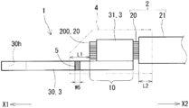
FIG. 1 is a schematic side view of a terminal-equipped wire for charging inlet according to one embodiment, and
FIG. 2 is a schematic top view of the terminal-equipped wire for charging inlet according to the embodiment.
DETAILED DESCRIPTION TO EXECUTE THE INVENTION Technical Problem
With the recent year development of electrically driven vehicles, a terminal-equipped wire for charging inlet tends to be used with a large current. Thus, a cross-sectional area of the wire tends to increase. It is difficult to bond a water stop portion to a large-diameter wire without gaps. Further, a conductor of the wire in which the large current flows tends to have a high temperature and the water stopping performance of the water stop portion may be reduced by a temperature increase. Therefore, it is desired to further improve the water stopping performance of the water stop portion and make the water stopping performance difficult to drop over a long period of time in the terminal-equipped wire for charging inlet.
Accordingly, one object of the present disclosure is to provide a terminal-equipped wire with a water stop portion excellent in water stopping performance.
Effect of Invention
The terminal-equipped wire of the present disclosure is provided with a molded resin portion serving as a water stop portion excellent in water stopping performance.
Description of Embodiments of Present Disclosure
The present inventors studied the configuration of a water stop portion in a terminal-equipped wire for charging inlet. In a terminal-equipped wire used with a large current, the number of strands constituting a conductor increases. If the number of the strands increases, more air is present in gaps between the strands. Accordingly, when the conductor generates heat due to the large current, a pressure inside an insulation coating is increased by air expansion. The present inventors acquired such knowledge that a considerable load was applied to the water stop portion due to this increase in the inner pressure of the wire. Based on this knowledge, the present inventors completed a terminal-equipped wire for charging inlet having a structure capable of withstanding an inner pressure increase of a wire. Embodiments of the present disclosure are listed and described below.
(1) A terminal-equipped wire according to an embodiment is a terminal-equipped wire for charging inlet with a wire including a conductor and an insulation coating, the insulation coating having an olefin-based resin as a main component, a terminal to be connected to the conductor exposed from an end part of the wire, a molded resin portion for covering a region from a connection point of the conductor and the terminal to the insulation coating, and a primer layer provided between an inner peripheral surface of the molded resin portion and an outer peripheral surface of the terminal, the inner peripheral surface of the molded resin portion and an outer peripheral surface of the insulation coating being directly in contact.
Here, the “main component” in this specification is a component most contained in a member.
The terminal-equipped wire according to the embodiment is provided with the molded resin portion excellent in water stopping performance and reliability.
The molded resin portion of the terminal-equipped wire functions as a water stop portion for suppressing the adhesion of moisture to the connection point of the terminal and the conductor. The primer layer is a layer containing a primer having affinity to the terminal made of metal and the molded resin portion. Thus, the terminal and the molded resin portion are particularly firmly bonded at the position of the primer layer and the intrusion of moisture to the connection point from the terminal side is effectively suppressed. Further, the molded resin portion formed by insert molding or the like is bonded to the insulation coating of the wire. Even if the primer layer is absent between the molded resin portion and the insulation coating, the intrusion of moisture to the connection point from the wire side is effectively suppressed. The bonding of the terminal and the molded resin portion and the bonding of the molded resin portion and the insulation coating are maintained for 120 hours in an environment having a temperature of 85° C. and a humidity of 85% as shown in a test example to be described later. From these, the molded resin portion of the terminal-equipped wire according to the embodiment is excellent in water stopping performance.
(2) As one aspect of the terminal-equipped wire according to the embodiment, the olefin-based resin is polyethylene or polypropylene.
Polyethylene and polypropylene are excellent in mechanical strength and insulation. Further, polyethylene and polypropylene are easily bonded to the molded resin portion made of resin.
(3) As one aspect of the terminal-equipped wire according to the embodiment, the primer layer has polyurethane or polypropylene as a main component.
Polyurethane and polypropylene are inexpensively and easily available. Further, polyurethane and polypropylene have affinity to both metal constituting the terminal and resin constituting the molded resin portion. Therefore, polyurethane and polypropylene are suitable as a material of the primer layer for improving the bondability of the molded resin portion to the terminal.
(4) As one aspect of the terminal-equipped wire according to the embodiment, the molded resin portion has polybutylene terephthalate or polyamide as a main component.
Polybutylene terephthalate and polyamide are excellent in heat resistance, durability and strength.
Details of Embodiment of Present Disclosure
Hereinafter, an embodiment of a terminal-equipped wire of the present disclosure is described based on the drawings. The same reference signs in figures denote the same components. Note that the present invention is not limited to a configuration shown in the embodiment, but is represented by claims and intended to include all changes in the scope of claims and in the meaning and scope of equivalents.
Embodiment 1
Hereinafter, a terminal-equipped wire 1 according to the embodiment is described based on FIGS. 1 and 2 .
((Overall Configuration))
A terminal-equipped wire 1 of this example shown in FIG. 1 is used in a charging inlet to be mounted in an electrically driven vehicle. The use of the terminal-equipped wire 1 in the charging inlet can be specified from the size of the terminal-equipped wire 1 and the like. Similarly to a conventional configuration, this terminal-equipped wire 1 is provided with a wire 2 and a terminal 3. The terminal-equipped wire 1 of this example is further provided with a molded resin portion 4 for constituting a water stop portion and a primer layer 5 for improving the water stopping performance of the molded resin portion 4. Each component of the terminal-equipped wire 1 of this example is described below. In describing each component, a leftward direction toward the tip of the terminal-equipped wire 1 in figures is defined as a first direction X1 and a rightward direction away from the tip of the terminal-equipped wire 1 in figures is defined as a second direction X2.
((Wire))
The wire 2 includes a conductor 20 and an insulation coating 21 covering the outer periphery of the conductor 20. The wire 2 used in the charging inlet extends from the charging inlet to a battery. An entire length of the wire 2 is, for example, 500 mm or more and 2,000 mm or less. The entire length of the wire 2 may be 1,000 mm or more and 1,800 mm or less. A branch part as in a wiring harness is not present in the wire 2 of this example.
An outer diameter of the conductor 20 is, for example, 13 mm or more. A large current flows in the wire 2 used in the charging inlet. If the outer diameter of the conductor 20 is 13 mm or more, a cross-sectional area of the conductor 20 capable of withstanding use with the large current is secured. The terminal-equipped wire 1 has a size mountable in the electrically driven vehicle. Accordingly, the outer diameter of the conductor 20 is practically preferably 20 mm or less. A preferable outer diameter of the conductor 20 is 16 mm or more and 18 mm or less.
The conductor 20 is a stranded wire obtained by stranding a plurality of strands 200. The strands 200 are, for example, made of copper, copper alloy, aluminum, aluminum alloy or the like.
The insulation coating 21 has a polyolefin-based resin as a main component. Polyethylene, polypropylene or the like can be, for example, cited as the polyolefin-based resin. The polyolefin-based resin is excellent in bondability to the molded resin portion 4 to be described later. General additives used in resin molding can be cited as substances contained in the insulation coating 21 other than the polyolefin-based resin. A stabilizer, an antioxidant, a lubricant, a filler, a colorant, a flame retardant and the like can be, for example, cited as the additives.
The polyolefin-based resin is poor in flexibility as compared to a silicone-based resin. Accordingly, the wire 2 provided with the insulation coating 21 made of polyolefin-based resin is slightly difficult to bend. However, since the wire 2 used in the charging inlet is long, a problem hardly occurs in the arrangement of the wire 2 in the electrically driven vehicle even if the wire 2 is slightly difficult to bend. The polyolefin-based resin is better in bondability to the molded resin portion 4 than the silicone-based resin. In terms of improving the water stopping performance of the terminal-equipped wire 1, the polyolefin-based resin is better as a material of the insulation coating 21 than the silicone-based resin.
A thickness of the insulation coating 21 is, for example, 1.4 mm or more and 2.0 mm or less. A large current flows in the wire 2 used in the charging inlet. If the thickness of the insulation coating 21 is 1.4 mm or more and 2.0 mm or less, the insulation of the wire 2 in which the large current flows can be secured.
((Terminal))
The terminal 3 of this example includes a body portion 30 in the form of a flat plate and a wire barrel portion 31 provided in the body portion 30. A length of the body portion 30 is, for example, 10 mm or more and 24 mm or less. A thickness of the body portion 30 is, for example, 1.8 mm or more and 4.0 mm or less. The body portion 30 of this size can secure a sufficient conductor cross-sectional area.
The body portion 30 is provided with a through hole 30 h. The through hole 30 h is used to fix the terminal 3 to a housing of the charging inlet.
The wire barrel portion 31 grips the conductor 20 exposed from the insulation coating 21. Projecting pieces are provided on both sides of the body portion 30 and bent to sandwich the conductor 20, thereby configuring the wire barrel portion 31. An insulation barrel for gripping the insulation coating 21 of the wire 2 is not present in the terminal 3 of this example.
The terminal 3 is made of metal excellent in electrical conductivity. For example, the terminal 3 is made of copper, copper alloy, aluminum, aluminum alloy, nickel, nickel alloy or the like. A plating layer may be provided on the surface of the terminal 3. Tin and the like can be, for example, cited as a material of the plating layer.
((Molded Resin Portion))
The molded resin portion 4 functions as a water stop portion for suppressing the adhesion of moisture to a connection point 10 of the conductor 20 of the wire 2 and the terminal 3. The molded resin portion 4 of this example covers a region from the connection point 10 of the terminal 3 and the conductor 20 to the insulation coating 21 of the wire 2. The connection point 10 means an entire part in which the conductor 20 and the terminal 3 overlap in a length direction of the conductor 20. Accordingly, the connection point 10 includes the entire wire barrel portion 31 gripping the conductor 20, a part of the body portion 30 corresponding to the conductor 20 and a part of the conductor 20 arranged on the body portion 30. In other words, the molded resin portion 4 covers the outer periphery of the conductor 20 so that the conductor 20 is not exposed to an outside environment.
The molded resin portion 4 extends further than the tip of the conductor 20 in the first direction X1. A distance L1 between an end part of the molded resin portion 4 and the tip of the conductor 20 in the first direction X1 is, for example, 5 mm or more and 15 mm or less. If the distance L1 is 5 mm or more, a sufficient contact area of the terminal 3 and the molded resin portion 4 is secured. As a result, the bonding of the terminal 3 and the molded resin portion 4 is strengthened. If the distance L1 is 15 mm or less, the molded resin portion 4 does not become excessively long. The distance L1 is more preferably 7 mm or more and 10 mm or less.
A distance L2 between an end part of the molded resin portion 4 and an end surface of the insulation coating 21 in the second direction X2 is, for example, 5 mm or more and 15 mm or less. If the distance L2 is 5 mm or more, a sufficient contact area of the insulation coating 21 and the molded resin portion 4 is secured. If the distance L2 is 15 mm or less, the molded resin portion 4 does not become excessively long. The distance L2 is more preferably 7 mm or more and 10 mm or less.
The molded resin portion 4 has resin as a main component. The resin is preferably polybutylene terephthalate (PBT) or polyamide (PA). PBT and PA are excellent in heat resistance, durability and strength. The molded resin portion 4 is obtained by insert molding. The molded resin portion 4 and the insulation coating 21 of the wire 2 easily adhere to each other by the heat of the resin during insert molding.
General additives used in resin molding can be cited as components other than the resin in the molded resin portion 4. A stabilizer, an antioxidant, a lubricant, a filler, a colorant, a flame retardant and the like can be, for example, cited as the additives.
The molded resin portion 4 is molded using a mold for accommodating only the tip of the wire 2 mounted on the terminal 3. In this example, the primer layer 5 is formed on the terminal 3 before the molded resin portion 4 is molded. A formation method of the primer layer 5 is described later.
((Primer Layer))
The primer layer 5 is a bonding auxiliary layer containing a primer for improving the bondability of the molded resin portion 4 to the terminal 3. The primer layer 5 is provided between the inner peripheral surface of the molded resin portion 4 and the outer peripheral surface of the terminal 3. More specifically, the primer layer 5 is provided between a part of the inner peripheral surface of the molded resin portion 4 and a part of the outer peripheral surface of the body portion 30 of the terminal 3. The primer layer 5 is provided at a position further than the tip of the conductor 20 in the first direction X1. In the terminal-equipped wire 1 of this example, a bonding auxiliary layer equivalent to the primer layer 5 is not present in parts other than between the molded resin portion 4 and the terminal 3.
The primer layer 5 is annularly formed around the outer periphery of the body portion 30. The primer layer 5 of this example is not divided in a circumferential direction of the body portion 30. A width W5 of the primer layer 5 is preferably 3 mm or more and 10 mm or less. If the width W5 is 3 mm or more, the molded resin portion 4 is firmly bonded to the terminal 3. If the width W5 is 10 mm or less, the enlargement of the molded resin portion 4 can be avoided. The width W5 is more preferably 4 mm or more and 6 mm or less.
The primer layer 5 has a primer having affinity to both metal and resin as a main component. The primer is preferably polyurethane (PU) or polypropylene (PP). PU and PP may be PU and PP in which some elements are substituted with other elements. Chlorinated PP in which one part of hydrogen is substituted with chlorine can be, for example, cited as such PP. PU and PP have affinity to both the terminal 3 and the molded resin portion 4. Therefore, the bondability of the molded resin portion 4 to the terminal 3 is improved by the primer layer 5.
The primer layer 5 is formed by applying a primer solution, in which the primer is dissolved in a solvent, to the terminal 3. The primer solution is dried after being applied to the terminal 3. By forming the molded resin portion 4 to include a part applied with the primer solution, the primer layer 5 is formed between the terminal 3 and the molded resin portion 4. Alcohols such as methanol, ethanol and butanol or organic solvents such as acetone and toluene can be cited as the solvent of the primer solution. The primer layer 5 may contain part of the solvent.
((Miscellaneous))
In the terminal-equipped wire 1 of this example, the inner peripheral surface of the molded resin portion 4 and the outer peripheral surface of the insulation coating 21 are directly in contact. The molded resin portion 4 is easily bonded to the outer periphery of the insulation coating 21 made of resin when being molded on the outer periphery of the insulation coating 21. Therefore, the molded resin portion 4 and the insulation coating 21 are firmly bonded even if the primer is not present between the molded resin portion 4 and the insulation coating 21.
((Effects))
The molded resin portion 4 of the terminal-equipped wire 1 of this example suppresses the adhesion of moisture to the connection point 10 of the terminal 3 and the conductor 20. The primer layer 5 provided between this molded resin portion 4 and the terminal 3 strengthens the bonding of the molded resin portion 4 and the terminal 3. Thus, the intrusion of moisture to the connection point 10 from the side of the terminal 3 in the molded resin portion 4 is effectively suppressed. Further, the olefin-based resin constituting the insulation coating 21 of the wire 2 is excellent in bondability to the molded resin portion 4. Thus, the intrusion of moisture to the connection point 10 from the side of the wire 2 in the molded resin portion 4 is effectively suppressed.
In the terminal-equipped wire 1 of this example, the material of the insulation coating 21 of the wire 2, that of the molded resin portion 4 and that of the primer layer 5 are optimally selected. Thus, the molded resin portion 4 exhibits high water stopping performance in the terminal-equipped wire 1 for charging inlet exposed to a severe use environment. Moreover, high water stopping performance is maintained over a long period of time.
In the terminal-equipped wire 1 of this example, the primer layer 5 is provided only in a small part of the inner peripheral surface of the molded resin portion 4. Therefore, the terminal-equipped wire 1 of this example is better in terms of time and effort for production and cost than a configuration in which the primer layer 5 is provided on the entire inner peripheral surface of the molded resin portion 4.
Test Example 1
In Test Example 1, a plurality of terminal-equipped wires different in the configuration of a primer layer were produced and the water stopping performance of a molded resin portion in each terminal-equipped wire was examined.
((Sample No. 1))
The terminal-equipped wire 1 of Sample No. 1 is the terminal-equipped wire 1 having a structure shown in FIG. 1 of the embodiment. Dimensions and materials of the respective components are as follows.
    • Wire 2
    • Entire length . . . 500 mm
    • Diameter . . . 16.9 mm
    • Thickness of insulation coating 21 . . . 1.6 mm
    • Material of insulation coating 21 . . . . PE resin
    • Terminal 3
    • Material . . . copper terminal with tin plating
    • Molded resin portion 4
    • Length . . . 40 mm
    • Material . . . PBT resin
    • Primer layer 5
    • Width W5 . . . 4 mm
    • Material . . . primer having polyurethane as a main component
      ((Sample No. 2))
The terminal-equipped wire 1 of Sample No. 2 is the same as the terminal-equipped wire 1 of Sample No. 1 except that the material of the primer layer 5 is a primer having chlorinated polypropylene as a main component.
((Test on Water Stopping Performance))
First, to reproduce the aging of the terminal-equipped wire 1 of each sample, an acceleration test was conducted by leaving the terminal-equipped wire 1 of each sample in the following environment.
    • Temperature . . . 85° C.
    • Humidity . . . 85%
    • Time . . . 120 hours
Subsequently, assuming a temperature when the terminal-equipped wire 1 of each sample is used, the terminal-equipped wire 1 of each sample was left in an atmosphere of 120° C.
Finally, the molded resin portion 4 of the terminal-equipped wire 1 of each sample was arranged in cold water, and air was fed into the inside of the wire 2 at a pressure of 10 kPa from an end part of the terminal-equipped wire 1 on a side opposite to the molded resin portion 4. Then, it was visually confirmed that a pressure value of a pressure meter indicated 10 kPa or more. If the pressure value of this pressure meter largely drops, it can be judged that leakage occurred at the position of the molded resin portion 4. The occurrence of leakage means that water is insufficiently stopped by the molded resin portion 4.
Leakage did not occur in both Sample No. 1 and Sample No. 2. Therefore, water stop between the terminal 3 and the molded resin portion 4 is thought to be ensured by the primer layer 5. Further, water stop between the insulation coating 21 of the wire 2 and the molded resin portion 4 is thought to be ensured even if a bonding auxiliary layer equivalent to the primer layer 5 is absent. From this result, it was found that the water stopping performance of the molded resin portion 4 was maintained over a long period of time according to the terminal-equipped wire 1 having the configuration according to the embodiment.
LIST OF REFERENCE NUMERALS
    • 1 terminal-equipped wire
      • 10 connection point
    • 2 wire
      • 20 conductor, 21 insulation coating, 200 strand
    • 3 terminal
      • 30 body portion, 31 wire barrel portion, 30 h through hole
    • 4 molded resin portion
    • 5 primer layer
    • L1, L2 distance
    • W5 width
    • X1 first direction, X2 second direction

Claims (5)

What is claimed is:
1. A terminal-equipped wire for charging inlet, comprising:
a wire including a conductor and an insulation coating, the insulation coating having an olefin-based resin as a main component;
a terminal to be connected to the conductor exposed from an end part of the wire;
a molded resin portion for covering a region from a connection point of the conductor and the terminal to the insulation coating; and
a primer layer provided between an inner peripheral surface of the molded resin portion and an outer peripheral surface of the terminal,
the inner peripheral surface of the molded resin portion and an outer peripheral surface of the insulation coating being directly in contact,
a direction toward a tip of the terminal being a first direction,
the molded resin portion extending further than a tip of the conductor in the first direction,
the primer layer being annular around an outer periphery of a part of the terminal located further than the tip of the conductor in the first direction, and
a width of the primer layer being 3 mm or more and 10 mm or less.
2. The terminal-equipped wire of claim 1, wherein the olefin-based resin is polyethylene or polypropylene.
3. The terminal-equipped wire of claim 1, wherein the primer layer has polyurethane or polypropylene as a main component.
4. The terminal-equipped wire of claim 1, wherein the molded resin portion has polybutylene terephthalate or polyamide as a main component.
5. The terminal-equipped wire of claim 1, wherein:
a direction opposite to the first direction is a second direction, and
a distance between an end part of the molded resin portion on the second direction side and an end of the insulation coating on the first direction side is 5 mm or more and 15 mm or less.
US18/011,296 2020-06-29 2021-06-21 Terminal-equipped wire Active 2041-12-16 US12166325B2 (en)

Applications Claiming Priority (3)

Application Number Priority Date Filing Date Title
JP2020112049A JP2022022609A (en) 2020-06-29 2020-06-29 Wire with terminal
JP2020-112049 2020-06-29
PCT/JP2021/023361 WO2022004457A1 (en) 2020-06-29 2021-06-21 Terminal-equipped electric wire

Publications (2)

Publication Number Publication Date
US20230352858A1 US20230352858A1 (en) 2023-11-02
US12166325B2 true US12166325B2 (en) 2024-12-10

Family

ID=79316169

Family Applications (1)

Application Number Title Priority Date Filing Date
US18/011,296 Active 2041-12-16 US12166325B2 (en) 2020-06-29 2021-06-21 Terminal-equipped wire

Country Status (4)

Country Link
US (1) US12166325B2 (en)
JP (1) JP2022022609A (en)
CN (1) CN115699461A (en)
WO (1) WO2022004457A1 (en)

Citations (12)

* Cited by examiner, † Cited by third party
Publication number Priority date Publication date Assignee Title
JPH11296646A (en) 1998-04-07 1999-10-29 Dainippon Printing Co Ltd IC card and method of making IC card
US20020027013A1 (en) * 1999-12-09 2002-03-07 Yazaki Corporation Terminal connecting portion of sheathed wire, method of waterproofing the same, and waterproofing apparatus using the method
WO2013089171A1 (en) 2011-12-16 2013-06-20 株式会社オートネットワーク技術研究所 Electrical wire provided with terminal and method for producing electrical wire provided with terminal
JP2016126981A (en) 2015-01-08 2016-07-11 株式会社オートネットワーク技術研究所 Waterproof wire harness
US20160254615A1 (en) * 2015-02-27 2016-09-01 Hitachi Metals, Ltd. Molded electric wire
US20170117640A1 (en) * 2015-10-22 2017-04-27 Carlisle Interconnect Technologies, Inc. Arc resistant power terminal
US20170323707A1 (en) * 2014-11-18 2017-11-09 Autonetworks Technologies, Ltd. Molded part-equipped electrical cable and molded part-equipped electrical cable manufacturing method
US20170324235A1 (en) * 2014-11-19 2017-11-09 Autonetworks Technologies, Ltd. Molded part-equipped electrical cable
JP2018133278A (en) 2017-02-17 2018-08-23 住友電装株式会社 Charging inlet
US20180336979A1 (en) * 2015-12-07 2018-11-22 Autonetworks Technologies, Ltd. Wire harness
US20190305443A1 (en) 2018-03-30 2019-10-03 Autonetworks Technologies, Ltd. Terminal-equipped wire and wire harness
US20200099147A1 (en) * 2018-09-21 2020-03-26 Carbice Corporation Coated electrical connectors and methods of making and using thereof

Family Cites Families (2)

* Cited by examiner, † Cited by third party
Publication number Priority date Publication date Assignee Title
JP2015118832A (en) * 2013-12-19 2015-06-25 住友電装株式会社 Wire harness and method of manufacturing the same
JP2017135118A (en) * 2017-03-24 2017-08-03 株式会社オートネットワーク技術研究所 Terminal

Patent Citations (12)

* Cited by examiner, † Cited by third party
Publication number Priority date Publication date Assignee Title
JPH11296646A (en) 1998-04-07 1999-10-29 Dainippon Printing Co Ltd IC card and method of making IC card
US20020027013A1 (en) * 1999-12-09 2002-03-07 Yazaki Corporation Terminal connecting portion of sheathed wire, method of waterproofing the same, and waterproofing apparatus using the method
WO2013089171A1 (en) 2011-12-16 2013-06-20 株式会社オートネットワーク技術研究所 Electrical wire provided with terminal and method for producing electrical wire provided with terminal
US20170323707A1 (en) * 2014-11-18 2017-11-09 Autonetworks Technologies, Ltd. Molded part-equipped electrical cable and molded part-equipped electrical cable manufacturing method
US20170324235A1 (en) * 2014-11-19 2017-11-09 Autonetworks Technologies, Ltd. Molded part-equipped electrical cable
JP2016126981A (en) 2015-01-08 2016-07-11 株式会社オートネットワーク技術研究所 Waterproof wire harness
US20160254615A1 (en) * 2015-02-27 2016-09-01 Hitachi Metals, Ltd. Molded electric wire
US20170117640A1 (en) * 2015-10-22 2017-04-27 Carlisle Interconnect Technologies, Inc. Arc resistant power terminal
US20180336979A1 (en) * 2015-12-07 2018-11-22 Autonetworks Technologies, Ltd. Wire harness
JP2018133278A (en) 2017-02-17 2018-08-23 住友電装株式会社 Charging inlet
US20190305443A1 (en) 2018-03-30 2019-10-03 Autonetworks Technologies, Ltd. Terminal-equipped wire and wire harness
US20200099147A1 (en) * 2018-09-21 2020-03-26 Carbice Corporation Coated electrical connectors and methods of making and using thereof

Non-Patent Citations (1)

* Cited by examiner, † Cited by third party
Title
International Search Report issued on Aug. 31, 2021 for WO 2022/004457 A1 (4 pages).

Also Published As

Publication number Publication date
US20230352858A1 (en) 2023-11-02
JP2022022609A (en) 2022-02-07
WO2022004457A1 (en) 2022-01-06
CN115699461A (en) 2023-02-03

Similar Documents

Publication Publication Date Title
JP5712911B2 (en) Electric wire with terminal and manufacturing method thereof
JP5177848B2 (en) Composite wire
US8011976B2 (en) Waterproof connector and method for producing the same
US20140179161A1 (en) Wire harness and connection structure of shield shell and braided shield
JP2012069449A (en) Crimp terminal, connection structure, and connector
US20190393686A1 (en) Wire harness
JP5454187B2 (en) Cable fixing method and cable connection part
JP2012089431A (en) Terminal crimping wire for vehicle
US10319497B2 (en) Molded portion-equipped electric cable and method for manufacturing molded portion-equipped electric cable
WO2009081679A1 (en) Composite electric wire
CN102113177A (en) Motor vehicle conductor connection element
US12166325B2 (en) Terminal-equipped wire
JP2016126981A (en) Waterproof wire harness
US12218474B2 (en) Terminal-equipped wire
JP2013120699A (en) Electric wire with terminal and method of manufacturing the same
JP2014107212A (en) Wire with terminal and manufacturing method therefor
JP2015176887A (en) Electromagnetic shield member and wire harness
US11410798B2 (en) Wire harness
JP6709705B2 (en) Wire with terminal
US20240317153A1 (en) Wire harness
CN223624749U (en) High-air-tightness automobile high-voltage wire harness
JP5885346B2 (en) Aluminum wire with crimp terminal and method for producing aluminum wire with crimp terminal
US20230231326A1 (en) Electric wire and terminal-equipped electric wire
US20160163423A1 (en) Shielded wire and wire harness
JP2007059123A (en) Electric wire for automobile

Legal Events

Date Code Title Description
AS Assignment

Owner name: SUMITOMO ELECTRIC INDUSTRIES, LTD., JAPAN

Free format text: ASSIGNMENT OF ASSIGNORS INTEREST;ASSIGNORS:HAMAGUCHI, TAKAAKI;KAWAKAMI, TAKASHI;NAKASHIMA, KAZUO;AND OTHERS;SIGNING DATES FROM 20221122 TO 20221125;REEL/FRAME:062141/0045

Owner name: SUMITOMO WIRING SYSTEMS, LTD., JAPAN

Free format text: ASSIGNMENT OF ASSIGNORS INTEREST;ASSIGNORS:HAMAGUCHI, TAKAAKI;KAWAKAMI, TAKASHI;NAKASHIMA, KAZUO;AND OTHERS;SIGNING DATES FROM 20221122 TO 20221125;REEL/FRAME:062141/0045

Owner name: AUTONETWORKS TECHNOLOGIES, LTD., JAPAN

Free format text: ASSIGNMENT OF ASSIGNORS INTEREST;ASSIGNORS:HAMAGUCHI, TAKAAKI;KAWAKAMI, TAKASHI;NAKASHIMA, KAZUO;AND OTHERS;SIGNING DATES FROM 20221122 TO 20221125;REEL/FRAME:062141/0045

FEPP Fee payment procedure

Free format text: ENTITY STATUS SET TO UNDISCOUNTED (ORIGINAL EVENT CODE: BIG.); ENTITY STATUS OF PATENT OWNER: LARGE ENTITY

STPP Information on status: patent application and granting procedure in general

Free format text: DOCKETED NEW CASE - READY FOR EXAMINATION

STPP Information on status: patent application and granting procedure in general

Free format text: NOTICE OF ALLOWANCE MAILED -- APPLICATION RECEIVED IN OFFICE OF PUBLICATIONS

STCF Information on status: patent grant

Free format text: PATENTED CASE