US12123797B2 - Method and a system for estimating the tension of a tension member - Google Patents
Method and a system for estimating the tension of a tension member Download PDFInfo
- Publication number
- US12123797B2 US12123797B2 US17/795,090 US202117795090A US12123797B2 US 12123797 B2 US12123797 B2 US 12123797B2 US 202117795090 A US202117795090 A US 202117795090A US 12123797 B2 US12123797 B2 US 12123797B2
- Authority
- US
- United States
- Prior art keywords
- tension member
- tension
- mass
- vibration
- vibration signal
- Prior art date
- Legal status (The legal status is an assumption and is not a legal conclusion. Google has not performed a legal analysis and makes no representation as to the accuracy of the status listed.)
- Active, expires
Links
Images


Classifications
-
- G—PHYSICS
- G01—MEASURING; TESTING
- G01L—MEASURING FORCE, STRESS, TORQUE, WORK, MECHANICAL POWER, MECHANICAL EFFICIENCY, OR FLUID PRESSURE
- G01L1/00—Measuring force or stress, in general
- G01L1/10—Measuring force or stress, in general by measuring variations of frequency of stressed vibrating elements, e.g. of stressed strings
-
- G—PHYSICS
- G01—MEASURING; TESTING
- G01L—MEASURING FORCE, STRESS, TORQUE, WORK, MECHANICAL POWER, MECHANICAL EFFICIENCY, OR FLUID PRESSURE
- G01L5/00—Apparatus for, or methods of, measuring force, work, mechanical power, or torque, specially adapted for specific purposes
- G01L5/04—Apparatus for, or methods of, measuring force, work, mechanical power, or torque, specially adapted for specific purposes for measuring tension in flexible members, e.g. ropes, cables, wires, threads, belts or bands
- G01L5/042—Apparatus for, or methods of, measuring force, work, mechanical power, or torque, specially adapted for specific purposes for measuring tension in flexible members, e.g. ropes, cables, wires, threads, belts or bands by measuring vibrational characteristics of the flexible member
-
- G—PHYSICS
- G01—MEASURING; TESTING
- G01L—MEASURING FORCE, STRESS, TORQUE, WORK, MECHANICAL POWER, MECHANICAL EFFICIENCY, OR FLUID PRESSURE
- G01L5/00—Apparatus for, or methods of, measuring force, work, mechanical power, or torque, specially adapted for specific purposes
- G01L5/24—Apparatus for, or methods of, measuring force, work, mechanical power, or torque, specially adapted for specific purposes for determining value of torque or twisting moment for tightening a nut or other member which is similarly stressed
-
- G—PHYSICS
- G01—MEASURING; TESTING
- G01M—TESTING STATIC OR DYNAMIC BALANCE OF MACHINES OR STRUCTURES; TESTING OF STRUCTURES OR APPARATUS, NOT OTHERWISE PROVIDED FOR
- G01M7/00—Vibration-testing of structures; Shock-testing of structures
-
- G—PHYSICS
- G01—MEASURING; TESTING
- G01M—TESTING STATIC OR DYNAMIC BALANCE OF MACHINES OR STRUCTURES; TESTING OF STRUCTURES OR APPARATUS, NOT OTHERWISE PROVIDED FOR
- G01M7/00—Vibration-testing of structures; Shock-testing of structures
- G01M7/02—Vibration-testing by means of a shake table
Definitions
- the invention relates to a method for estimating the tension of a tension member based on vibration signals. Furthermore, the invention relates to a system for estimating the tension of a tension member.
- tension members are pre-tensioned to a certain degree so that the structure is held together by the axial force in the tension member.
- the tension member may loosen due to vibrations of the structure, erroneous under-tightening from the beginning, thermal effects or other.
- it is important to be able to estimate the tension of the tension member at any point in the lifetime of the structure.
- a tension member Disclosed is a method for estimating the tension of a tension member, the method comprising the steps of:
- Estimating the tension of the tension member may be performed by modelling the tension member as a beam model, e.g. according to Euler-Bernoulli beam theory or Timoshenko beam theory. Modelling the tension member according to any of such theories requires the knowledge of certain parameters, which take into account a mixture of the set-up of the beam model, dimensions, material and other. These parameters are included in the equations which describe the deformations and vibrations of such beams. However, determining these parameters may be relatively difficult due to the number of available equations to solve the unknown parameters (i.e. boundary stiffness and axial tension).
- the vibration signal could comprise transverse bending vibrations, longitudinal vibrations and torsional vibrations.
- the vibration signal could comprise a mixture of these types of vibrations.
- tension member should be understood as a bolt, a stud, a cable, tension rod, rivet or other type of tension member which may clamp or support at least two elements due to the tensile load on the tension member.
- a stud is a rod that is threaded on both ends; the thread may extend along the complete length of the rod. Nuts can then be attached to both ends of the stud.
- the sampling could be performed by sampling of accelerations (e.g. by use of accelerometer), velocity, displacement, audio signals or other.
- the tension member is modified by modifying the mass and/or rotational inertia at the boundaries of the tension member.
- the tension member may be modelled by use of a suitable beam model.
- a suitable beam model requires various boundary conditions being representative of the actual physical constraints.
- Modifying the mass and/or rotational inertia at the boundaries is advantageous in that it is possible to change vibrational response from the tension member without affecting the boundary stiffness and tension of the tension member and without introducing new unknown parameters into the set of equations. Thus, it is possible to compare the vibration signals (one with and one without the modification) more easily so that the tension of the tension member may be estimated.
- the step of modifying the tension member comprises increasing the mass between 5 and 80 percent, preferably between 7 and 70 percent and most preferred between 10 and 50 percent of the mass of the tension member.
- the modification increases the mass of the tension member too much, the physical behaviour (e.g. axial tension and boundary stiffness) may be severely affected and if the modification increases the mass of the tension member too little, the effect of the modification may not be distinct enough so that a clear distinction between the two vibration signals is not possible, i.e. the difference may “drown” in signal noise.
- the above-mentioned range represents an advantageous relationship between ease of signal processing and accurate mathematical representation.
- the mass or the rotational inertia of the tension member is modified by attaching a mass on a first end and/or a second end of the tension member.
- the calculations required to estimate the tension in the tension member are simpler if the mass is attached to an end of the tension member e.g. because the location of an end of the tension member is always well defined whereas locating the mass between the ends would also require further measurements and calculation adjustments in relation to the specific location. Furthermore, it is advantageous if a mass is attached to either of the ends of the tension member in that it provides for an easy way of modifying the tension member by simply adding a mass to the ends. This mass could be screwed, glued, welded, clamped or in any other ways attached to either of the ends of the tension member.
- a mass could be a nut, a washer, a threaded block, a lump mass or anything else that may be attached to the tension member so that the mass is increased at one or both of the ends of the tension member.
- the mass should be attached to the ends so that it may vibrate together with the tension member—however, without altering the physical behaviour of the tension member.
- the attached mass should only affect the boundary stiffness and/or rotational inertia.
- the boundary conditions of the first end and the second end of the tension member are asymmetric when the mass and/or the rotational inertia of the tension member is modified.
- the boundary conditions at the ends of the tension member asymmetric (i.e. the first end boundary conditions are different from the second end or vice versa) in that it is thereby easier to mathematically distinguish between the ends of the tension member so that an accidental substitution may be avoided. Furthermore, by doing so, it is possible to obtain a mathematical model which may easier and faster converge towards a (correct) solution where the boundary stiffnesses have not been switched (this would not correspond to reality and result in erroneous theoretical vibration signal).
- the estimation is performed by use of a non-linear regression model.
- the estimation may be performed by using an error function, which minimizes the error between a set of guessed parameters and a new estimate.
- This error function may be minimized (in order to converge towards a solution) by use of a non-linear regression model.
- the error function is also non-linear.
- the non-linear regression model could be an exhaustive search algorithm, non-linear least squares, Gauss method of minimization or any other type of non-linear regression model which may be used to minimize an error function by an iterative procedure.
- estimation is performed by use of a Gauss method of minimization.
- Gauss method of minimization or Gauss-Newton algorithm
- the step of modifying the tension member comprises an increase of the rotational inertia of between 0.1 and 10 percent, preferably between 0.5 and 8 percent and most preferred between 1 and 5 percent of the rotational inertia of the tension member.
- the modification increases the rotational inertia of the tension member too much, the physical behaviour (e.g. axial tension and boundary stiffness) may be affected and if the modification increases the rotational inertia of the tension member too little, the effect of the modification may not be distinct enough so that a clear distinction between the two vibration signals is not possible, i.e. the difference may “drown” in signal noise.
- the above-mentioned range represents an advantageous relationship between ease of signal processing and accurate mathematical representation (free body diagram of the tension member).
- the tension member is a bolt or a stud.
- the tension member is a bolt or a stud because such tension members are widely used in engineering structures and machine design for providing a firm connection between two structures. Furthermore, bolts and studs are specifically designed to be used as tension elements in that they are usually preloaded with some pre-tension. Even further, the threaded parts of the bolt or stud makes it easy to attach additional mass, exciting means, sampling means or other tightly and securely to the tension member.
- the tension member is a bolt in that the bolt may be represented by beam models and is therefore suitable for the method according to the present invention.
- the tension member is excited with a piezoelectric plate or an impact hammer.
- the tension member is excited with a piezoelectric plate or an impact hammer in that a precisely timed excitation may be performed. Furthermore, the precise impact force may be used to excite the tension member so that the right vibration response is obtained.
- the right vibration response is understood as the vibration response wherein the theoretical vibration signal is expected to be.
- the first vibration signal and/or the second vibration signal is sampled by use of an accelerometer or a piezoelectric plate.
- piezoelectric elements provide an inexpensive, durable and reliable way of sampling the first vibration signal and/or the second vibration signal in that piezoelectric elements provides an output signal in volts by means of which the natural frequency easily can be identified.
- the first vibration signal and the second vibration signal are the transverse bending natural frequency.
- the first and the second vibration signal is the transverse bending natural frequency in that this bending frequency is the easiest to obtain large amplitude vibrations due to the typical slenderness of a tension member. Furthermore, it is possible to calculate a theoretical transverse bending natural frequency which may then be correlated with the actual measurements. Thus, it is advantageous if the vibration signals are the transverse bending natural frequency in that it is easier to “tune” into the right frequency range since it is calculated before-hand and one may know at which frequency range the natural frequency is expected to be located in.
- transverse bending natural frequency is related to the axial tension. Therefore, measuring the transverse bending natural frequency may be correlated to the axial load and therefore the tension in the tension member.
- the tension member is pre-tensioned with a pre-stress of between 30 and 90 percent, preferably between 50 and 85 percent and most preferred between 60 and 80 percent of the yield strength of the tension member.
- the vibration response is related to the tension of the tension member in such a way that the amplitude is dependent on the tension of the tension member.
- the damping is high whereas if the tension is high, the damping is low. It is important that the damping is not too high as this would make the relationship between the tension and vibration response non-linear, which is not desired as the mathematical beam model is a linear model—more specifically, the transverse natural frequencies should not be amplitude dependent.
- the tension in the tension member may also not be too high as this could potentially damage the tension member.
- the invention provides for a system for estimating the tension of a tension member, the system comprising excitation means for inducing vibrations on the tension member, sampling means for sampling the vibrations of the tension member when said excitation means excite said tension member, mass modifying means arranged for modifying the mass and/or inertia of the tension member, and processing means arranged for comparing the sampled vibrations and thereby estimate the tension of the ⁇ tension member.
- Excitation means should be understood as a piezoelectric plate, impact hammer, piezoelectric actuator or other type of excitor.
- sampling means should be understood as accelerometers, piezoelectric plate or element, velocity sensor or other type of sampler.
- Mass modifying means should be understood as any type of mass modifier capable of modifying the tension member by modifying the mass or rotational inertia by e.g. adding a nut, removing material at the boundaries, adding a lumped mass or other.
- Processing means should be understood as a computer, a processing unit, a mechanical processing unit, a software for processing data or any other type of processor.
- system is arranged to perform the method according to any of the previously described methods.
- the system could be a device including the excitation means, sampling means, mass modifying means, processing means in a single cabinet which is transportable by the personnel who may perform the inspection of the tension.
- the system/device may communicate with an external unit which may perform the estimation which requires some computation power.
- the system or device may be arranged to estimate the tension of the tension member one by one or multiple tension members at once so that the process of estimating a plurality of tension members is sped up.
- the method further comprises checking if the estimated tension of the tension member is within a predefined tension range.
- the method according to the present invention comprise checking if the estimated tension of the tension member is within a predefined tension range in that it hereby is possible to provide an output signal—e.g. a visual or audio signal to an operator—regarding the tension state of the specific tension member, which will enable the operator or other to correct the tension state—if this is not correct—immediately or at least mark the tension members that subsequently needs tension adjustment.
- an output signal e.g. a visual or audio signal to an operator—regarding the tension state of the specific tension member, which will enable the operator or other to correct the tension state—if this is not correct—immediately or at least mark the tension members that subsequently needs tension adjustment.
- a computer program for estimating the tension of a tension member, comprising instructions which when the program is executed by a computer causes the computer to carry out the following steps
- the computer may preferably comprise memory and a processor to execute the computer program using the memory.
- the computer program may have access to a cloud solution for retrieving tension member properties (dimensions, type, material etc.) and also for outputting and storing the tension estimates.
- the invention also relates to use of a method according to any of the previously discussed methods for estimating the tension of a bolt or a stud.
- Using the method according to the present invention in relation to bolts or studs is particularly advantageous in that these elements are very standardized and thereby particularly suited for the present method. Furthermore, the threaded parts of the bolts or studs make it easy to attach additional mass, exciting means, sampling means or other tightly and securely to the tension member.
- FIG. 1 a illustrates a tension member clamping two elements together as seen from the side
- FIG. 1 b illustrates a tension member being excited as seen from the front
- FIG. 2 a illustrates a modified tension member clamping two elements together as seen from the side
- FIG. 2 b illustrates a modified tension member being excited as seen from the front
- FIG. 3 illustrates the steps of estimating the tension of a tension member
- FIG. 4 illustrates a free-body-diagram of a tension member modelled as a beam.
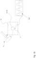
- FIG. 1 a illustrates a tension member 1 clamping two elements 13 together as seen from the side.
- the figure also illustrates a typical application of a tension member 1 .
- the working principle is that the tension member 1 is subjected to an axial pre-tension so that the material elasticity results in a clamping force on the elements 13 and thereby holds the elements 13 together.
- the bolted elements 13 may be parts of an engine, wind turbine, bridge or any other engineering construction involving bolted joints or members being connected by a tension member.
- the tension member may comprise a nut 14 and a tension member head 16 so that a moment may be applied to it so as to produce the axial tension.
- the structure also comprises a force washer 12 for sensing the applied load as the setup is also a test rig for the purpose of carrying out the invention.
- the force washer is not necessarily present or may be replaced by a regular washer.
- the tension member 1 is an M12 bolt.
- other type of bolts may be used as well as other types of tension members as previously mentioned.
- the tension member 1 could be an anchored bolt or stud where only one end of the tension member is accessible or the tension member 1 could be a stud with nuts attached at one or both ends.
- the tension member 1 is pre-tensioned with a pre-stress of 60 percent of the yield strength of the tension member 1 but in another embodiment the tension member 1 could pre-tensioned with a pre-stress of 10 percent, 40 percent or even in some embodiments 100 percent of the yield strength of the tension member 1 .
- FIG. 1 b illustrates a tension member 1 being excited as seen from the front.
- a first vibration signal VS 1 the tension member 1 is excited so that the tension member 1 vibrates. These vibrations are captured by the accelerometer 7 which measures the transverse accelerations as illustrated by the wave signal—which is not necessarily representative of an actual vibrational response of the tension member 1 .
- the tension member 1 is excited by use of an impact hammer 6 .
- the tension member may be excited by any other excitation means as mentioned previously.
- the accelerometer is positioned at the first end 4 .
- the accelerometer may be positioned at the second end 5 .
- the impact point may be on any point of the tension member 1 , however preferably on either end.
- the excitation means 6 may impact the tension member 1 from any direction (e.g. transverse, longitudinal or other, or a combination of these).
- the accelerometer communicates by wire with a monitor (which may comprise a monitor for displaying the vibration signal), but it may also communicate wirelessly.
- FIG. 2 a illustrates a modified tension member 1 a clamping two elements 13 together as seen from the side.
- the step of modifying the tension member 1 may e.g. be performed by adding a nut 14 on the second end 5 so that the boundary mass and/or the rotational inertia is increased.
- the tension member 1 in this embodiment is a bolt
- the mass 14 may easily be added to the second end 5 of the bolt by simply screwing the mass 14 onto the threaded portion of the bolt.
- the tension member was a stud
- the mass 14 may easily be added to the first end 4 or the second end 5 of the stud by simply screwing the mass 14 onto the threaded portion of the stud.
- the added mass 15 is a nut 14 .
- the added mass 15 could be any of the previously described mass modifying means.
- FIG. 2 b illustrates a modified tension member 1 a being excited as seen from the front.
- the second vibration signal VS 2 is different from the first vibration signal VS 1 .
- the second vibration signal VS 2 is clearly affected by the addition of the added mass 15 which, in this embodiment, affects the boundary conditions so that the vibration characteristics has been altered.
- the tension of the tension member can be estimated based on a comparison of the first vibration signal VS 1 and the second vibration signal VS 2 as described in the following.
- the method could further comprise the step of comparing the estimated tension of the tension member 1 with a desired tension e.g. to provide information regarding whether or not the specific tension member 1 is within the correct tension range in the specific application. I.e.
- the method could include providing input regarding the specific tension member—such at type, size, make, model, material and/or other—and e.g. the specific application or location, so that a desired tension range may be established e.g. by means of a database, a look-up table, additional input or other and so that the method includes checking if the estimated tension is within the desired tension range.
- the method may then further include providing a signal to the operator or others regarding whether or not estimated tension of the tension member 1 is within the desired tension range.
- FIG. 3 illustrates the steps of estimating the tension of a tension member 1 .
- the ordering of the steps may be switched so that the modified tension member 1 a is excited first followed by the “non” modified tension member 1 .
- this is of course obvious from the method as described as the step of modification is, in essence, just a tension member modified relative to its previous state.
- the step of removing the mass is obviously also a modification.
- FIG. 4 illustrates a free-body-diagram of a tension member 1 modelled as a beam.
- a non-linear regression may be used to fit the parameters to measured natural frequencies (i.e. the measured natural frequencies extracted from the first and second vibration signal VS 1 and VS 2 , respectively).
- the first term is the deviation between measured natural frequencies and the model predicted undamped natural frequencies (damping may be neglected in the model since it has an insignificant effect on the natural frequency).
- the second term represents the deviations between a posteriori guess of the unknown parameters contained in ⁇ tilde over (p) ⁇ s and new estimate ⁇ circumflex over (p) ⁇ s .
- W and U are weighting matrices, where W indicates the confidence in the measured natural frequencies, and U the confidence in the a posteriori estimate.
- the other parameters in the equation are vectors.
- the above error function may be minimized by use of Gauss method of minimization, setting the weight matrices and a posteriori, stop criteria and a posteriori updates and choosing new a posteriori estimates if the estimated parameters are unrealistic or do not converge towards a solution.
Landscapes
- Physics & Mathematics (AREA)
- General Physics & Mathematics (AREA)
- Force Measurement Appropriate To Specific Purposes (AREA)
Applications Claiming Priority (4)
| Application Number | Priority Date | Filing Date | Title |
|---|---|---|---|
| EP20154878 | 2020-01-31 | ||
| EP20154878.1 | 2020-01-31 | ||
| EP20154878 | 2020-01-31 | ||
| PCT/DK2021/050027 WO2021151444A1 (en) | 2020-01-31 | 2021-01-27 | A method and a system for estimating the tension of a tension member |
Publications (2)
| Publication Number | Publication Date |
|---|---|
| US20230048801A1 US20230048801A1 (en) | 2023-02-16 |
| US12123797B2 true US12123797B2 (en) | 2024-10-22 |
Family
ID=69423169
Family Applications (1)
| Application Number | Title | Priority Date | Filing Date |
|---|---|---|---|
| US17/795,090 Active 2041-07-24 US12123797B2 (en) | 2020-01-31 | 2021-01-27 | Method and a system for estimating the tension of a tension member |
Country Status (5)
| Country | Link |
|---|---|
| US (1) | US12123797B2 (de) |
| EP (1) | EP4097438B1 (de) |
| ES (1) | ES3031516T3 (de) |
| PL (1) | PL4097438T3 (de) |
| WO (1) | WO2021151444A1 (de) |
Families Citing this family (2)
| Publication number | Priority date | Publication date | Assignee | Title |
|---|---|---|---|---|
| IT202300019341A1 (it) | 2023-09-20 | 2025-03-20 | S2X S R L | Sistema per il monitoraggio automatico dei parametri modali e dello sforzo di trazione in cavi o stralli in presenza di elementi di ricoprimento |
| CN118603387A (zh) * | 2024-03-27 | 2024-09-06 | 广东思谷智能技术有限公司 | 一种新型的金刚线张力标定方法 |
Citations (6)
| Publication number | Priority date | Publication date | Assignee | Title |
|---|---|---|---|---|
| SU509798A1 (ru) | 1974-05-15 | 1976-04-05 | Ленинградское Отделение Центральногонаучно-Исследовательского И Проектногоинститута Строительных Металлокон-Струкций | Способ испытани конструкций |
| US4062229A (en) * | 1977-02-22 | 1977-12-13 | General Electric Company | Method of testing the integrity of installed rock bolts |
| US4709182A (en) * | 1985-06-20 | 1987-11-24 | Veb Chemieanlagenbaukombinat Leipzig/Grimma | Method and apparatus for tightening or loosening screw-type connections |
| US20110130975A1 (en) | 2009-08-17 | 2011-06-02 | Fdh Engineering, Inc. | Method of Determining Tension in a Rod |
| CN105571763A (zh) | 2015-12-14 | 2016-05-11 | 新疆金风科技股份有限公司 | 螺栓预紧力检测方法及装置 |
| WO2017203220A1 (en) | 2016-05-24 | 2017-11-30 | Wheelsure Technologies Limited | Method and apparatus for measuring resonant frequency of an article and for monitoring tensile load in a bolt |
-
2021
- 2021-01-27 WO PCT/DK2021/050027 patent/WO2021151444A1/en not_active Ceased
- 2021-01-27 PL PL21701388.7T patent/PL4097438T3/pl unknown
- 2021-01-27 ES ES21701388T patent/ES3031516T3/es active Active
- 2021-01-27 US US17/795,090 patent/US12123797B2/en active Active
- 2021-01-27 EP EP21701388.7A patent/EP4097438B1/de active Active
Patent Citations (7)
| Publication number | Priority date | Publication date | Assignee | Title |
|---|---|---|---|---|
| SU509798A1 (ru) | 1974-05-15 | 1976-04-05 | Ленинградское Отделение Центральногонаучно-Исследовательского И Проектногоинститута Строительных Металлокон-Струкций | Способ испытани конструкций |
| US4062229A (en) * | 1977-02-22 | 1977-12-13 | General Electric Company | Method of testing the integrity of installed rock bolts |
| US4709182A (en) * | 1985-06-20 | 1987-11-24 | Veb Chemieanlagenbaukombinat Leipzig/Grimma | Method and apparatus for tightening or loosening screw-type connections |
| US20110130975A1 (en) | 2009-08-17 | 2011-06-02 | Fdh Engineering, Inc. | Method of Determining Tension in a Rod |
| CN105571763A (zh) | 2015-12-14 | 2016-05-11 | 新疆金风科技股份有限公司 | 螺栓预紧力检测方法及装置 |
| CN105571763B (zh) | 2015-12-14 | 2018-08-07 | 新疆金风科技股份有限公司 | 螺栓预紧力检测方法及装置 |
| WO2017203220A1 (en) | 2016-05-24 | 2017-11-30 | Wheelsure Technologies Limited | Method and apparatus for measuring resonant frequency of an article and for monitoring tensile load in a bolt |
Non-Patent Citations (1)
| Title |
|---|
| International Search Report and Written Opinion for PCT/DK2021/050027, dated Apr. 28, 2021, 8 pages. |
Also Published As
| Publication number | Publication date |
|---|---|
| PL4097438T3 (pl) | 2025-06-02 |
| ES3031516T3 (en) | 2025-07-09 |
| EP4097438A1 (de) | 2022-12-07 |
| EP4097438B1 (de) | 2025-04-16 |
| EP4097438C0 (de) | 2025-04-16 |
| US20230048801A1 (en) | 2023-02-16 |
| WO2021151444A1 (en) | 2021-08-05 |
Similar Documents
| Publication | Publication Date | Title |
|---|---|---|
| JP4158367B2 (ja) | 振動試験装置ならびに振動応答評価方法 | |
| US4164149A (en) | Method and system for monitoring the angular deformation of structural elements | |
| JP4992084B2 (ja) | 構造物の損傷の診断システムおよび方法 | |
| EP2444787A1 (de) | Methode und Vorrichtung für Brückezustandbewertung von dynamischen Methode | |
| CN105527179A (zh) | 多轴共振疲劳试验的方法及装置 | |
| CN108195535A (zh) | 基于非线性激振特征的螺栓结合部松动检测方法及系统 | |
| US12123797B2 (en) | Method and a system for estimating the tension of a tension member | |
| WO2021158198A2 (en) | A novel experimental modal analysis method based on response control approach for nonlinear engineering structures | |
| JP3837099B2 (ja) | 構造物の損傷推定システムおよびプログラム | |
| RU2542589C2 (ru) | Способ реконструкции трехмерного образа физического состояния объекта мониторинга в измерительной точке | |
| Fraraccio et al. | Identification and damage detection in structures subjected to base excitation | |
| JP3640583B2 (ja) | 地震応答解析方法 | |
| JPH07113721A (ja) | 構造物の振動試験装置、振動試験方法、および、振動試験用治具 | |
| JP3145625B2 (ja) | 配管系疲労評価装置 | |
| Mendonça et al. | Prediction of dynamic responses in a rectangular beam using the modal expansion method | |
| Ardelean et al. | Cable effects study: Tangents, rat holes, dead ends, and valuable results | |
| JP3847264B2 (ja) | 地震応答解析方法 | |
| Latini et al. | Experimental results of nonlinear structure coupled through nonlinear connecting elements | |
| JP2004045294A (ja) | 構造物の損傷危険度判定システムおよびプログラム | |
| Gueorguiev et al. | Frequency characteristics of seismic piezoelectric sensors under one-dimensional mechanical action | |
| Sadeqi et al. | Accelerometer configuration assessment of Milad Tower utilizing operational modal analysis | |
| Schürger et al. | Modal analysis of beam oscillation | |
| Emory et al. | Experimental modal analysis of rectangular and circular beams | |
| Tartibu et al. | Modal testing of a simplified wind turbine blade | |
| Vári et al. | Strain modal testing-a critical appraisal |
Legal Events
| Date | Code | Title | Description |
|---|---|---|---|
| FEPP | Fee payment procedure |
Free format text: ENTITY STATUS SET TO UNDISCOUNTED (ORIGINAL EVENT CODE: BIG.); ENTITY STATUS OF PATENT OWNER: LARGE ENTITY |
|
| FEPP | Fee payment procedure |
Free format text: ENTITY STATUS SET TO SMALL (ORIGINAL EVENT CODE: SMAL); ENTITY STATUS OF PATENT OWNER: LARGE ENTITY |
|
| AS | Assignment |
Owner name: DANMARKS TEKNISKE UNIVERSITET, DENMARK Free format text: ASSIGNMENT OF ASSIGNORS INTEREST;ASSIGNORS:BROENS, MARIE;THOMSEN, JON JUEL;SIGNING DATES FROM 20210311 TO 20210315;REEL/FRAME:061563/0001 |
|
| STPP | Information on status: patent application and granting procedure in general |
Free format text: DOCKETED NEW CASE - READY FOR EXAMINATION |
|
| STPP | Information on status: patent application and granting procedure in general |
Free format text: NON FINAL ACTION MAILED |
|
| STPP | Information on status: patent application and granting procedure in general |
Free format text: RESPONSE TO NON-FINAL OFFICE ACTION ENTERED AND FORWARDED TO EXAMINER |
|
| ZAAB | Notice of allowance mailed |
Free format text: ORIGINAL CODE: MN/=. |
|
| STPP | Information on status: patent application and granting procedure in general |
Free format text: AWAITING TC RESP., ISSUE FEE NOT PAID |
|
| STPP | Information on status: patent application and granting procedure in general |
Free format text: NOTICE OF ALLOWANCE MAILED -- APPLICATION RECEIVED IN OFFICE OF PUBLICATIONS |
|
| AS | Assignment |
Owner name: DANMARKS TEKNISKE UNIVERSITET, DENMARK Free format text: CHANGE OF ADDRESS;ASSIGNOR:DANMARKS TEKNISKE UNIVERSITET;REEL/FRAME:068986/0443 Effective date: 20210418 |
|
| FEPP | Fee payment procedure |
Free format text: ENTITY STATUS SET TO UNDISCOUNTED (ORIGINAL EVENT CODE: BIG.); ENTITY STATUS OF PATENT OWNER: LARGE ENTITY |
|
| STPP | Information on status: patent application and granting procedure in general |
Free format text: PUBLICATIONS -- ISSUE FEE PAYMENT VERIFIED |
|
| STCF | Information on status: patent grant |
Free format text: PATENTED CASE |