US12097553B2 - Investment casting shell binders and compositions - Google Patents
Investment casting shell binders and compositions Download PDFInfo
- Publication number
- US12097553B2 US12097553B2 US17/270,130 US201917270130A US12097553B2 US 12097553 B2 US12097553 B2 US 12097553B2 US 201917270130 A US201917270130 A US 201917270130A US 12097553 B2 US12097553 B2 US 12097553B2
- Authority
- US
- United States
- Prior art keywords
- binder
- shell
- investment casting
- slurry
- mfc
- Prior art date
- Legal status (The legal status is an assumption and is not a legal conclusion. Google has not performed a legal analysis and makes no representation as to the accuracy of the status listed.)
- Active, expires
Links
Images


Classifications
-
- B—PERFORMING OPERATIONS; TRANSPORTING
- B22—CASTING; POWDER METALLURGY
- B22C—FOUNDRY MOULDING
- B22C1/00—Compositions of refractory mould or core materials; Grain structures thereof; Chemical or physical features in the formation or manufacture of moulds
- B22C1/16—Compositions of refractory mould or core materials; Grain structures thereof; Chemical or physical features in the formation or manufacture of moulds characterised by the use of binding agents; Mixtures of binding agents
- B22C1/20—Compositions of refractory mould or core materials; Grain structures thereof; Chemical or physical features in the formation or manufacture of moulds characterised by the use of binding agents; Mixtures of binding agents of organic agents
- B22C1/26—Compositions of refractory mould or core materials; Grain structures thereof; Chemical or physical features in the formation or manufacture of moulds characterised by the use of binding agents; Mixtures of binding agents of organic agents of carbohydrates; of distillation residues therefrom
-
- B—PERFORMING OPERATIONS; TRANSPORTING
- B22—CASTING; POWDER METALLURGY
- B22C—FOUNDRY MOULDING
- B22C1/00—Compositions of refractory mould or core materials; Grain structures thereof; Chemical or physical features in the formation or manufacture of moulds
- B22C1/16—Compositions of refractory mould or core materials; Grain structures thereof; Chemical or physical features in the formation or manufacture of moulds characterised by the use of binding agents; Mixtures of binding agents
- B22C1/18—Compositions of refractory mould or core materials; Grain structures thereof; Chemical or physical features in the formation or manufacture of moulds characterised by the use of binding agents; Mixtures of binding agents of inorganic agents
- B22C1/183—Sols, colloids or hydroxide gels
-
- B—PERFORMING OPERATIONS; TRANSPORTING
- B22—CASTING; POWDER METALLURGY
- B22C—FOUNDRY MOULDING
- B22C1/00—Compositions of refractory mould or core materials; Grain structures thereof; Chemical or physical features in the formation or manufacture of moulds
- B22C1/16—Compositions of refractory mould or core materials; Grain structures thereof; Chemical or physical features in the formation or manufacture of moulds characterised by the use of binding agents; Mixtures of binding agents
- B22C1/20—Compositions of refractory mould or core materials; Grain structures thereof; Chemical or physical features in the formation or manufacture of moulds characterised by the use of binding agents; Mixtures of binding agents of organic agents
- B22C1/22—Compositions of refractory mould or core materials; Grain structures thereof; Chemical or physical features in the formation or manufacture of moulds characterised by the use of binding agents; Mixtures of binding agents of organic agents of resins or rosins
- B22C1/2206—Compositions of refractory mould or core materials; Grain structures thereof; Chemical or physical features in the formation or manufacture of moulds characterised by the use of binding agents; Mixtures of binding agents of organic agents of resins or rosins obtained by reactions only involving carbon-to-carbon unsaturated bonds
- B22C1/2213—Polyalkenes
-
- B—PERFORMING OPERATIONS; TRANSPORTING
- B22—CASTING; POWDER METALLURGY
- B22C—FOUNDRY MOULDING
- B22C1/00—Compositions of refractory mould or core materials; Grain structures thereof; Chemical or physical features in the formation or manufacture of moulds
- B22C1/16—Compositions of refractory mould or core materials; Grain structures thereof; Chemical or physical features in the formation or manufacture of moulds characterised by the use of binding agents; Mixtures of binding agents
- B22C1/20—Compositions of refractory mould or core materials; Grain structures thereof; Chemical or physical features in the formation or manufacture of moulds characterised by the use of binding agents; Mixtures of binding agents of organic agents
- B22C1/22—Compositions of refractory mould or core materials; Grain structures thereof; Chemical or physical features in the formation or manufacture of moulds characterised by the use of binding agents; Mixtures of binding agents of organic agents of resins or rosins
- B22C1/2206—Compositions of refractory mould or core materials; Grain structures thereof; Chemical or physical features in the formation or manufacture of moulds characterised by the use of binding agents; Mixtures of binding agents of organic agents of resins or rosins obtained by reactions only involving carbon-to-carbon unsaturated bonds
- B22C1/222—Polyacrylates
-
- B—PERFORMING OPERATIONS; TRANSPORTING
- B22—CASTING; POWDER METALLURGY
- B22C—FOUNDRY MOULDING
- B22C1/00—Compositions of refractory mould or core materials; Grain structures thereof; Chemical or physical features in the formation or manufacture of moulds
- B22C1/16—Compositions of refractory mould or core materials; Grain structures thereof; Chemical or physical features in the formation or manufacture of moulds characterised by the use of binding agents; Mixtures of binding agents
- B22C1/20—Compositions of refractory mould or core materials; Grain structures thereof; Chemical or physical features in the formation or manufacture of moulds characterised by the use of binding agents; Mixtures of binding agents of organic agents
- B22C1/22—Compositions of refractory mould or core materials; Grain structures thereof; Chemical or physical features in the formation or manufacture of moulds characterised by the use of binding agents; Mixtures of binding agents of organic agents of resins or rosins
- B22C1/2206—Compositions of refractory mould or core materials; Grain structures thereof; Chemical or physical features in the formation or manufacture of moulds characterised by the use of binding agents; Mixtures of binding agents of organic agents of resins or rosins obtained by reactions only involving carbon-to-carbon unsaturated bonds
- B22C1/2226—Polymers containing halogens
-
- B—PERFORMING OPERATIONS; TRANSPORTING
- B22—CASTING; POWDER METALLURGY
- B22C—FOUNDRY MOULDING
- B22C1/00—Compositions of refractory mould or core materials; Grain structures thereof; Chemical or physical features in the formation or manufacture of moulds
- B22C1/16—Compositions of refractory mould or core materials; Grain structures thereof; Chemical or physical features in the formation or manufacture of moulds characterised by the use of binding agents; Mixtures of binding agents
- B22C1/20—Compositions of refractory mould or core materials; Grain structures thereof; Chemical or physical features in the formation or manufacture of moulds characterised by the use of binding agents; Mixtures of binding agents of organic agents
- B22C1/22—Compositions of refractory mould or core materials; Grain structures thereof; Chemical or physical features in the formation or manufacture of moulds characterised by the use of binding agents; Mixtures of binding agents of organic agents of resins or rosins
- B22C1/2233—Compositions of refractory mould or core materials; Grain structures thereof; Chemical or physical features in the formation or manufacture of moulds characterised by the use of binding agents; Mixtures of binding agents of organic agents of resins or rosins obtained otherwise than by reactions only involving carbon-to-carbon unsaturated bonds
- B22C1/2266—Polyesters; Polycarbonates
-
- B—PERFORMING OPERATIONS; TRANSPORTING
- B22—CASTING; POWDER METALLURGY
- B22C—FOUNDRY MOULDING
- B22C1/00—Compositions of refractory mould or core materials; Grain structures thereof; Chemical or physical features in the formation or manufacture of moulds
- B22C1/16—Compositions of refractory mould or core materials; Grain structures thereof; Chemical or physical features in the formation or manufacture of moulds characterised by the use of binding agents; Mixtures of binding agents
- B22C1/20—Compositions of refractory mould or core materials; Grain structures thereof; Chemical or physical features in the formation or manufacture of moulds characterised by the use of binding agents; Mixtures of binding agents of organic agents
- B22C1/22—Compositions of refractory mould or core materials; Grain structures thereof; Chemical or physical features in the formation or manufacture of moulds characterised by the use of binding agents; Mixtures of binding agents of organic agents of resins or rosins
- B22C1/2293—Natural polymers
-
- B—PERFORMING OPERATIONS; TRANSPORTING
- B22—CASTING; POWDER METALLURGY
- B22C—FOUNDRY MOULDING
- B22C9/00—Moulds or cores; Moulding processes
- B22C9/02—Sand moulds or like moulds for shaped castings
- B22C9/04—Use of lost patterns
Definitions
- the present invention relates to investment casting shell composition binders, investment casting shell compositions and methods for the preparation thereof.
- the present invention also relates to investment casting shells and investment casting methods for creating an article.
- the present invention also relates to kits for preparing investment casting compositions.
- Investment casting also known as lost wax, lost pattern or precision casting, is a process for producing metal articles.
- the process typically involves the steps of: (1) preparing a disposable preform of the article (e.g. formed of wax); (2) building a ceramic casting shell around the preform; (3) removing the disposable preform (e.g. dewaxing); (4) sintering the casting shell; (5) pouring molten metal into the casting shell; (6) allowing the metal to cool within the casting shell; and (7) removing the casting shell.
- a disposable preform of the article e.g. formed of wax
- building a ceramic casting shell around the preform e.g. dewaxing
- removing the disposable preform e.g. dewaxing
- Suitable disposable materials for the preform in step (1) include any material that will melt, vaporise or burn whilst leaving the casting shell intact. Wax is typically used, although polystyrene and certain polymers may also be used.
- the ceramic casting shell in step (2) is typically formed around the disposable preform pattern by dipping the preform into an investment casting shell slurry to form one or more shell layers on the preform.
- an investment casting shell slurry is formed from a mixture of refractory materials and binders.
- the refractory material can be comprised of alumina (Al 2 O 3 ), silica (SiO 2 ), zircon (ZrSiO 4 ), aluminosilicate (Al 2 SiO 5 ).
- the binders can be alcohol- or water-based, and commonly comprise colloidal silica or ethyl silicate.
- slurry compositions for investment casting shells comprise 75-80% of refractory material and 20-25% binders.
- Each slum coating is usually followed with a stucco coating to complete a shell layer. Once the shell layers have been applied, the green investment casting shell is allowed to air dry. These steps are repeated to build successive layers until the casting shell has the desired thickness.
- Step (3) Removal of the disposable preform in step (3), e.g. dewaxing, is commonly achieved by steam autoclaving or flash firing. During this step, the disposable preform is melted, vaporised or burnt away leaving the green shell mould having a negative imprint of the article.
- Sintering of the shell in step (4) can be initiated by pressure or by firing. However, firing is conventionally used. Sintering fuses the shell into a denser mass, lowers the permeability and effectively increases the shell strength.
- the fired shell mould is then filled with molten metal in step (5).
- This can be achieved using a variety of methods including gravity filling, pressure filling, vacuum filling and/or filling by centrifugal force.
- shell failure typically occurs at step (3) as the disposable material expands into the shell and at step (5) when molten metal is poured into the fired shell, as well as during handling as the shell is moved between equipment from one step to another.
- Shell strength can be improved by increasing the number of layers of slurry and stucco applied, thereby increasing the shell thickness.
- each additional slurry coat increases the length of the investment casting process, as each layer must be dried sufficiently before another layer is formed on top.
- the increase in material resource also increases the cost of the process.
- a first aspect of the invention provides an investment casting shell composition binder, the binder comprising hydrophilic fibrils having an average diameter between about 1 nm and about 1 ⁇ m.
- the hydrophilic fibrils have an average diameter between about 1 nm to less than about 1 ⁇ m, between about 10 nm to less than about 1 ⁇ m, between about 20 nm to less than about 1 ⁇ m, between about 10 nm and about 900 nm, between about 20 nm to about 100 nm, between about 50 nm to about 500 nm, between about 50 nm to about 400 nm, between about 50 nm to about 350 nm, between about 100 nm to about 400 nm, between about 100 nm to about 350 nm, between about 100 nm to 300 nm, and combinations of end points thereof.
- the hydrophilic fibrils have an average diameter less than about 1 ⁇ m, less than about 900 nm, less than about 500 nm, less than about 400 nm, less than about 300 nm.
- the hydrophilic fibrils have an average length of between about 100 nm to about 100 ⁇ m, between about 500 nm to about 100 ⁇ m, between about 10 ⁇ m to about 100 ⁇ m.
- the hydrophilic fibrils may have an average length of between about 500 nm to about 4 ⁇ m, or between about 1 ⁇ m and about 3 ⁇ m.
- the hydrophilic fibrils have an aspect ratio (length to width ratio) of 15 or above, 20 or above, 25 or above, 50 or above.
- the hydrophilic fibrils may have an aspect ratio of up to 300.
- hydrophilic means an affinity for water.
- the hydrophilicity of the fibrils may be determined by the molecular structure of the fibrils.
- the hydrophilic fibrils may comprise —OH groups available for hydrogen bond donation.
- the hydrophilic fibrils may further be insoluble in water.
- investment casting shells prepared from compositions comprising hydrophilic fibrils in the binder resulted in shells with consistently thicker coating layers (e.g., up to 30% thicker) and increased strength (e.g., up to 40% more force required to break the shell). Furthermore, the resulting investment casting shells were found to have increased permeability. The combined strength and permeability was a surprising result, since an increase in shell permeability is usually associated with a decrease in shell strength.
- porosity in the context of the present invention refers to the fraction of empty (void) spaces in the shell.
- a shell with high porosity may not necessarily have high permeability.
- the hydrophilic fibrils comprise cellulose fibrils.
- the hydrophilic fibrils may be derived from a natural source, for example, from natural fibres produced by plants, animal or geological processes. Natural fibres include cellulose, chitin, chitosan, collagen, keratin and tunican.
- the hydrophilic fibrils e.g. cellulose fibrils
- the hydrophilic fibrils are derived from a raw material selected from the group consisting of: trees, vegetables, sugar beets, citrus fruits and combinations thereof.
- the hydrophilic fibres may be comprised of or provided as fibrillated fibres.
- the hydrophilic fibrils may be derived from a fibre or fibres that have been subjected to fibrillation.
- fibrillation refers to the splitting of fibres into fibrils. Fibrillation of a fibre, which may be a natural fibre, synthetic fibre or a regenerated fibre, causes external and internal segments of the fibre surface to partially detach from the main fibre structure. The fibrils may be attached by one segment to the main fibre structure. The fibrils may attach to other fibrils to form a three dimensional network. Fibrillation may be achieved using any known technique, for example, mechanically or thermomechanically, chemically, or a combination thereof.
- the fibrils have a significantly greater combined surface area compared to the original fibres.
- the hydrophilic fibrils may be derived or formed synthetically, or by any other known method.
- the hydrophilic fibrils comprise microfibrillated cellulose (MFC).
- MFC microfibrillated cellulose
- CNF cellulose nanofibres
- NCC nanocrystalline cellulose
- CNC cellulose nanocrystals
- the hydrophilic fibrils are non-ionic.
- the hydrophilic fibrils are made from wood pulp from pine, preferably spruce.
- the hydrophilic fibrils comprise cellulose that is unmodified compared to the cellulose in the feedstock used to make the hydrophilic fibrils.
- the hydrophilic fibrils are made by breaking down wood pulp using enzymes and/or mechanical methods.
- Fibres have diameters on the micro- to milli-scale, whereas fibrils have diameters on the nanometer scale, i.e. 1 nm to 1 ⁇ m.
- pulped cellulose fibres typically have a diameter in the range 2 ⁇ m to 80 ⁇ m, and length in the range 0.005 mm to 10 mm.
- microfibrillated cellulose (MFC) fibrils have diameters between 1 nm to 1 ⁇ m. Due to the complex three-dimensional structure of MFC, it is difficult to define the length of each individual fibril. Each fibril forms a network with other fibrils, which together can form lengths of several micrometers.
- the hydrophilic fibrils are present in an amount from about 0.1 wt % to about 20 wt % based on the total mass of the binder, preferably from about 0.1 wt % to about 5 wt % based on the total mass of the binder, from about 0.2 wt % to about 4 wt % based on the total mass of the binder, or 0.2 wt % to about 0.4 wt % based on the total mass of the binder. In some embodiments, the hydrophilic fibrils are present in an amount of at least about 0.2 wt % based of the total mass of the binder, at least about 0.25 wt % based of the total mass of the binder.
- the hydrophilic fibrils are present in an amount at most about 0.5 wt % based on the total mass of the binder, at most about 0.45 wt % based on the total mass of the binder or at most about 0.4% based on the total mass of the binder.
- the binder may further comprise colloidal silica.
- the binder may comprise ethyl silicate.
- silica particles from the colloid may form hydrogen bonds with the hydrophilic fibrils in the binder. This is thought to contribute to the formation of a robust ceramic matrix for investment casting shells, thus improving shell build and strength.
- the binder may further comprise at least one additional polymer.
- the at least one additional polymer comprises one or more monomers selected from the list consisting of: acrylic acid, acrylic esters, methacrylic acid, methacrylic esters, styrene, butadiene, vinyl chloride, vinyl acetate, and combinations thereof.
- the at least one additional polymer comprises styrene.
- styrene polymers have been found to provide increased green strength, i.e. breakage resistance, by imparting flexibility to the shell.
- the at least one additional polymer comprises a styrene butadiene copolymer.
- the at least one additional polymer comprises a styrene acrylate copolymer.
- styrene polymers may form hydrogen bonds with the hydrophilic fibrils in the binder, thus improving shell build thickness and strength.
- the at least one additional polymer may be present in an amount from about 0 to about 20 wt % based on the total mass of the binder, about 5 to about 15 wt/o based on the total mass of the binder, or about 10 to about 15 wt % based on the total mass of the binder. In one embodiment, the at least one additional polymer is present in an amount of about 12 wt % based on the total mass of the binder.
- the binder may further comprise at least one additional agent selected from the list consisting of: a wetting agent, an anti-foam agent, a pH modifier, a bactericide and a fungicide.
- wetting agent also known as a surfactant, refers to a chemical substance that increases the spreading properties of a liquid by lowering surface tension.
- Wetting agents can be used in investment casting shell slurries to improve adhesion between the slurry and the wax pattern.
- anti-foam agent also known as a defoamer, refers to a substance that reduces or prevents the formation of foam in a liquid.
- Anti-foam agents can be used in investment shell slurries to reduce the formation of bubbles which improves adhesion of the slurry to the wax pattern and improves the surface finish of the final product.
- the pH of the binder can have a significant effect on the binder properties.
- colloidal silica particles are negatively charged with a pH around 10. At pH levels below 9.0, colloidal silica particles can start to gel, thus a pH of pH 9.4 or above is preferred.
- pH modifiers can be used to control the pH of the binder.
- bactericide also referred to as a biocide, refers to a chemical substance that reduces or prevents growth of bacteria.
- fungicide refers to a chemical substance that reduces or prevents growth of fungi. Bacteria and fungal growth in an investment casting shell slurry can cause the pH to drop leading to gelation which shortens the shelf life of investment casting compositions and weakens the resulting shells.
- a second aspect of the invention provides an investment casting shell composition comprising the binder described herein and a refractory component.
- the composition can be provided as a slurry.
- slurry refers to a semi-liquid mixture comprising solid particles suspended in a solvent.
- an investment casting slurry refers to the composition that the disposable preform pattern is dipped in to form a layer around the preform to build the investment casting shell.
- the binder is present in the composition at a concentration of from 20 wt % to 40 wt % based on the total mass of the composition.
- the binder may be provided as a colloidal solution (sol) in water or alcohol.
- the hydrophilic fibrils in the binder are present in an amount from about 0.01 wt % to about 1 wt % based on the total mass of the composition, about 0.01 wt/o to about 0.5 wt % based on the total mass of the composition, about 0.05 wt % to about 0.2 wt % based on the total mass of the composition, or about 0.05 wt % to about 0.15 wt % based on the total mass of the composition.
- the refractory component may comprise at least one selected from the list consisting of: fused silica (SiO 2 ), aluminosilicate (Al 2 SiO 5 ), alumina (Al 2 O 3 ), zirconium silicate (ZrSiO 4 ), microsilica, zirconia (ZrO 2 ), zircon (ZrSiO 4 ), yttira (Y 2 O 3 ), quartz, carbon and combinations thereof.
- the refractory component may comprise fused silica of: mesh 120, mesh size 140, mesh 170, mesh 200, mesh 270, mesh 325, or combinations thereof.
- the refractory component comprises fused silica with particle size distribution comprising a d10 value in the range of about 5 ⁇ m to about 15 ⁇ m, a d50 value in the range of about 35 ⁇ m to about 55 ⁇ m, and a d90 value in the range of about 90 ⁇ m to about 110 ⁇ m, a D[3,2] value in the range from about 10 ⁇ m to about 15 ⁇ m and a D[4,3] value in the range from about 40 ⁇ m to about 60 ⁇ m
- the d10 value refers to the diameter at which 10% of particles are less than the given value
- the d50 value refers to the diameter at which 50% of particles are less than the given value
- the d90 value refers to the diameter at which 90% of particles are less than the given value.
- D[3,2] refers to the surface mean diameter and D[4,3] refers to the volume mean diameter.
- the refractory component comprises aluminosilicate. In some embodiments, the refractory component comprises calcined kaolin aluminasilicate.
- the refractory component comprises a particle size distribution comprising the parameters of d10 of about 9 ⁇ m, d50 of about 46 ⁇ m and d90 of about 99 ⁇ m, D[3,2] of about 12 ⁇ m and D[4,3] of about 57 ⁇ m.
- the refractory component comprises a particle size distribution comprising the parameters of d10 of about 5 ⁇ m, d50 of about 31 ⁇ m, d90 of about 99. D[3,2] of about 12 ⁇ m and D[4,3] of about 43 ⁇ m.
- the refractory component comprises a wide distribution fused silica flour.
- Wide distribution fused silica flours may be prepared by combining an amount of fine silica particles with an amount of larger silica particles.
- the wide distribution silica flour may be composed of between 80% to 90% of 50-80 mesh silica (average size approx. 200 microns), and between 10 to 20% of 120 mesh silica (average size approx. 125 microns).
- silica mesh 200 The particle size distributions of silica mesh 200, silica mesh 270 and a wide distribution flour comprising 85% 50-80 mesh and 15% 120 mesh (EZ CastTM, Remet UK Ltd) are also shown in FIG. 15 .
- a third aspect of the invention provides an investment casting shell prepared from the investment casting shell composition described herein.
- a fourth aspect of the invention provides a method of preparing an investment casting shell composition, the method comprising: i) mixing hydrophilic fibrils in an aqueous solvent; (ii) adding the mixture in (i) to a container comprising colloidal silica to form a binder; (iii) optionally adding one or more additional agents comprising: a polymer, an anti-foam agent, a pH modifier, a bactericide and a fungicide to the binder; (iv) mixing the binder with a refractory component to form a slurry.
- a fifth aspect of the invention provides an investment casting method for creating an article, the method comprising coating an expendable preform with at least one coat of an investment casting shell slurry, wherein at least one of the slurry coats comprises the investment casting shell composition described herein.
- the slurry coats in the second layer and above comprise the investment casting shell composition described herein.
- the slurry coats may be formed by dipping the preform in the investment casting shell composition described herein.
- the first slurry coat e.g. prime coat
- the first slurry coat does not comprise the investment casting shell composition described herein—i.e. the first slurry coat comprises a different, known prime coat composition.
- the method further comprises stuccoing one or more of the at least one slurry coats, wherein a slurry coat and a stucco coat produced by the stuccoing create a shell layer, wherein each shell layer once dried is at least 1 mm thick, preferably at least 1.1 mm thick, more preferably at least 1.2 mm thick, even more preferably at least 1.3 mm thick.
- the final layer of the investment casting shell mould does not comprise a stucco coat.
- the method comprises applying at least 2 layers, at least 3 layers, at least 4 layers, at least 5 layers, at least 6 layers of the investment casting shell composition. In some embodiments, the method comprises applying at most 7 layers, at most 6 layers, at most 5 layers, at most 4 layers, at most 3 layers of the investment casting shell composition.
- the method may further comprise the step of drying each layer before applying a subsequent layer.
- the method may further comprise the step of drying the coated pre-form to produce a green investment casting shell.
- the investment casting shell compositions of the present invention provide shells with thicker shell layers compared to conventional compositions and fewer layers are required to arrive at the same shell build thickness. Accordingly, the shell build time may be significantly reduced, thus providing time and cost savings.
- the investment casting shell method of the invention further provides investment casting shells with improved strength and versatility.
- the method may further comprise the step of heating the green investment casting shell mould to produce a fired investment casting shell mould.
- the method may further comprise the step of replacing the expendable preform pattern with a molten material, for example, molten metal.
- the method may further comprise the step of allowing the molten material to solidify in the investment casting shell mould to produce an article.
- the “prime coat” or prime layer refers to the first layer of the investment casting shell that is formed around the disposable preform pattern.
- the prime coat is formed by applying a coat of investment casting slurry to the preform, optionally followed by a stucco coat.
- the prime coat should have good adhesion to the disposable preform so that an accurate pattern mould is created and resistance to reaction with the molten metal during pouring. For this reason, the slurry for the prime coat may comprise a different composition to the slurry for the subsequent back-up and seal coats.
- the prime coat may comprise the same composition as the back-up coat or seal coat.
- a solvent sometimes referred to as a “pattern wash” may be used to wash the wax pattern prior to applying the first slurry coat.
- the use of a pattern wash promotes adherence of the slurry to the wax surface by removing dirt or residual mould release agents which may have been left on the wax.
- the pattern wash may be petroleum based.
- the term “stucco” refers to a material made of aggregates.
- the stucco may comprise: silica, alumina, zircon, aluminosilicate, mullite and/or chromite.
- binders of the invention comprising MFC were found to have good chemical stability, for example, gelation of the binder component of the slurry did not occur after at least 71 days when subjected to an accelerated gel test (held in an airtight bottle in an oven at 60° C.).
- the binders comprising MFC were also found to have good physical stability and maintained a good distribution without separation. This is in contrast to binders comprising macro scale fibres where separation could be observed after just a few hours.
- Green shell testing is performed to establish the ability of the shell to withstand handling, as well as the process of removing the disposable preform (e.g. “dewaxing”).
- the preform e.g. wax
- the shell must be sufficiently strong to maintain its shape and strength for the next stage of the process.
- the flexibility imparted by the polymer component of the binders of the invention is particularly beneficial at this stage of the lost wax cast process.
- Hot shell testing i.e. where the shell is tested after firing at around 1000° C.
- This stage is usually carried out in a furnace at temperatures of around 1000° C., at which temperature any organic matter contained in the shell is burned out.
- the shell must be strong enough to withstand high temperatures within the furnace, as well as mechanical distortion caused by impact as the molten metal is poured into the shell.
- Modulus of rupture also known as flexural strength, bend strength or fracture strength, is defined as the stress in a material as it is bent just before it yields (breaks). MOR is usually measured in megapascals (MPa), i.e. the force (N) required to break 1 m 2 of the material.
- MPa megapascals
- N force required to break 1 m 2 of the material.
- the force of break also known as break strength, is defined as the compressive load required to fracture a material. This measurement is particularly important for investment casting shells, as it indicates the load that the shell can withstand before breaking. A high force of break is critical to prevent leaks or failure when molten metal is poured into the shell for casting.
- MOR is a measure per cross sectional area
- the force of break is a more accurate measure of the strength of casting shells.
- MOR modulus of rupture
- MOR modulus of rupture
- MOR modulus of rupture
- FIG. 15 shows a comparison of the particle size distributions for various fused silica refractories: 200 mesh, 270 mesh and a wide distribution fused silica refractory:
- FIG. 19 shows the effect of MFC on the viscosity of various binder systems
- FIG. 20 shows the effect of MFC on the rheology of various binder systems
- FIG. 26 shows the effect of addition of fHDPE or MFC on the shear rate-dependent viscosities of various binder systems.
- FIG. 27 shows the effect of addition of fHDPE or MFC on the relationship between shear stress and shear rate for various binder systems.
- Example formulation 1 formulation 2 Conventional (0.1% (0.2% Ingredients (no MFC)/kg MFC)/kg MFC)/kg 200 mesh fused silica 91 91 91 (Imerys Fused Minerals) Colloidal silica (Remasol ® 45.5 45.5 45.5 SP-30; Grace GMBH) Styrene butadiene 6.5 6.5 6.5 copolymer (Lipaton SB 5843; Synthomer plc) * Wetting agent, ethoxylated 0.113 0.113 0.113 akyl acid phosphate (Victawet ® 12, ILCO Chemie) Anti-foaming agent, 0.091 0.091 0.091 polysiloxane dispersion (Burst 100; Remet Corporation) ⁇ circumflex over ( ) ⁇ Microfibrillated cellulose 0 0.552 1.104 (Exilva ® P 01-V, 10% aqueous dispersion; Borregaard) * Lipaton SB
- Example formulation 3 Ingredients (no MFC)/kg (0.3% MFC)/kg 200 mesh fused silica (Imerys 700 700 Fused Minerals) Colloidal silica (Remasol ® 350 350 SP-30; Grace GMBH) Styrene butadiene copolymer 50 50 (Lipaton SB 5843; Synthomer plc)* Wetting agent (Wet-in ®; 10 10 Remet Corporation) # Anti-foaming agent (Burst 2.5 2.5 100; Remet Corporation) ⁇ circumflex over ( ) ⁇ Microfibrillated cellulose 0 12.4 (Exilval ® P 01-V, 10% concentration; Borregaard) *Lipaton SB 5843 may be replaced with an equal amount of Adbond ® BV (Remet Corporation).
- ⁇ circumflex over ( ) ⁇ Burst- 100 may be replaced with an equal amount of Fumexol ® (Huntsman Textile Effect).
- # Wet-in ® may be replaced with an equal amount of Victawet ® 12 (ILCO Chemie).
- ⁇ circumflex over ( ) ⁇ Burst 100 may he replaced with an equal amount of Fumexol ® (Huntsman Textile Effect). # Wet-int may be replaced with an equal amount of Victawet ® 12 (TECO Chemie), 1.3 Binder Formulation for Warehouse Scale Trials
- Example formulation 5 Ingredients (0.3% MFC)/kg Colloidal silica (Remasol ® 192 SP-30; Grace GMBH) Styrene butadiene copolymer 19.2 (Lipaton SB 5843; Synthomer plc)* Deionised water 19.2 Biocide (Acticide ® MBS 1.2 50:501,2-Benzisothiazol- 3(2H)-one:2-methyl-2H- isothiazol-3-one; Thor Specialities) Anti-foaming agent (Burst 1.2 100; Remet Corporation) Microfibrillated cellulose 7.2 (Exilva ® P 01-V, 10% concentration; Borregaard) *Lipaton SB 5843 may be replaced with an equal amount of Adbond ® BV (Remet Corporation). ⁇ circumflex over ( ) ⁇ Burst 100 may he replaced with an equal amount of Fumexol ® (Huntsman Textile Effect).
- Viscosity adjustments were carried out by adding deionised water (to lower viscosity) or allowing water to evaporate from the slurry (to increase viscosity).
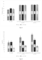
- Example 2 Modulus of Rupture (MOR) Shell Build Thickness and Force of Break
- Example slurry formulations 1 and 2 were prepared as set out in Table 1. Each slurry was tested at a viscosity of 25 seconds and 30 seconds respectively.
- Example formulation 3 was prepared as set out in Table 2 to a viscosity of 25 seconds.
- the results show a significant increase in shell thickness for the same number of coats for slurry compositions comprising 0.3% MFC, compared to the conventional slurry composition. For example, an average of about 30% increase in shell thickness for 9 coats, and about 16% increase in shell thickness for 6 coats.
- the force of break is also significantly improved for shells made from slurries comprising 0.3% MFC in the binder, compared to shells made from conventional slurries. For example, on average 40% more force is required to break a green shell having 8 back up coats and 1 seal coat prepared from a slurry comprising 0.3% MFC in the binder compared to a conventional slurry that does not comprise MFC in the binder. For a hot shell, on average 23% more force is required to break the shell.
- Example formulation 3 The investment casting shell formulation of Example formulation 3 was prepared, except with 0.4% MFC in the binder.
- the slurry produced investment casting shells with a significantly increased shell build compared to the conventional slurry, e.g. around 68% increase for 3 coats and around 76% increase for 4 coats (see FIG. 7 ).
- the slurry was found to have inconsistent working characteristics and did not cover the wax bars as effectively as compositions comprising 0.3% MFC in the binder.
- Example formulations 1.2 and 3 were prepared according to Table 1. Slurries of Example formulations 1 and 2 were tested at viscosities of 25 seconds and 30 seconds respectively. A conventional slurry and a slurry comprising Example formulation 3 (Table 2) was also prepared to a viscosity of 25 seconds.
- the BSI (BS 1902: Section 10.2:1994) approved method for permeability testing was followed.
- ping-pong balls Five plastic ping-pong balls were attached to hollow glass rods (impervious mullite) and the junction between rod and ball sealed with wax. The ping-pong balls were then dipped in the test slurry following the dipping protocol set out in Table 7 below to form a shell and left to dry in a temperature controlled room (airflow 0.6 m/s; humidity 45% RH; temperature 25° C.).
- Each coated ball was fired up to a temperature of 1000° C., to burn out the ping-pong ball from the shell.
- the temperature was increased using the heating ramp rate shown in Table 8.
- K Permeability of each shell was measured by passing nitrogen gas (1.05 PSI) through the glass rod and through the shell sample, and the flow rate was calculated in ml/min. The sample was then broken and the average thickness measured.
- Permeability was tested immediately after firing at 1000° C. (hot). After firing, the balls were allowed to cool for 24 hours at room temperature and permeability was retested (cold).
- results show an increase in permeability for slurries of the same viscosity as the concentration of MFC increases. This result may be explained by the fact that MFC is an organic material which burns out at elevated temperatures, thus leaving voids in the shell matrix and increasing permeability in the hot and cold shells.
- a slurry was prepared according to formulation 3, except that instead of 0.3% MFC, 0.3% of nylon fibre (12.4 kg) having an average diameter of 52 ⁇ m and an average length 0.5 mm was used.
- MOR, thickness and force of break measurements were taken according to the methods described in Example 2. The results are shown in FIGS. 9 - 11 . The results show that in contrast to MFC, the addition of fibres having a diameter in the micron range does not significantly improve shell build or break strength.
- Example formulation 3 and a conventional slurry comprising no MFC were prepared according to Table 2, and the properties of the slurries were evaluated using the protocols described below. The results are shown in Table 9.
- % total solids a measure of all active ingredients in the slurry, i.e. all the slurry components with the water removed.
- the total solids in the slurry was determined using a moisture balance (Mettler MJ33). A sample of slurry was dried at 140° C., until a stable weight was achieved and the percentage of solids calculated. Alternatively, this measurement may be taken by oven drying the sample at 140° C., for around an hour and calculating the percentage solids.
- Slurry density defined as the specific gravity (SG) of the slurry, i.e. the ratio of the density of the slurry material compared to water. SG was measured using a hydrometer or by weighing a sample of slurry and comparing to a sample of water.
- a slurry sample was centrifuged at 4600 rpm for around 30 minutes, decanted into a fresh vial and centrifuged again at 4600 rpm for around 30 minutes. The supernatant binder was retrieved from the top of the vial. The binder properties were evaluated using the protocols described below.
- % binder solids measured in the same way as described for the “% total solids” but using a sample of the binder supernatant.
- % silica measured by loss on ignition. A sample of binder supernatant was fired at 980° C., for 60 minutes and calculating the percentage of silica residue directly. Alternatively, the percentage silica can be found by measuring the specific gravity (SG) of the binder supernatant, e.g. using a volumetric flask and a precision balance, and the SG measurement can be converted to percentage silica by looking up the conversion in the appropriate table.
- SG specific gravity
- % polymer solids calculated as the difference between the binder solids at 140° C., and the percentage silica measured by loss on ignition.
- the “% polymer concentrate” is twice the percentage of polymer solids.
- Bacteria count measured by taking a sample of the supernatant binder, pipetting onto a culture slide and incubating at 30° C., for 48 hours. Bacterial infection, if present, would have shown on the culture slides as stains which can be compared to a standard control slide.
- Binder viscosity measured using a Brookfield Viscometer (60 rpm, 23-25° C.).
- Accelerated gel test a test to simulate accelerated aging of the slurry and therefore gelation.
- the binder supernatant was held at 60° C., for 48 hours in an air tight bottle (equivalent to around 1 month at room temperature). A “pass” was recorded if there was no significant change in viscosity.
- Example formulation 5 The binder used for the preparation of Example formulation 5 (see Table 4) was prepared in the warehouse as follows.
- Adbond® BV polymer (Remet Corporation) or Lipaton SB 5843 (Synthomer plc) was then added slowly to the drum and stirring continued for a further 15-20 minutes.
- 1.2 kg of biocide Acticide® MBS 50:50 1,2-Benzisothiazol-3(2H)-one:2-methyl-2H-isothiazol-3-one; Thor Specialities
- slurries were prepared having 6% 3% and 0% styrene butadiene polymer (Adbond® BV, Remet Corporation or Lipaton SB 5843, Synthomer plc) in the binder. MOR, shell thickness and force of break testing was carried out at green and hot (1000° C.)—see Example 2 for sample preparation and test protocols. The results are shown in FIGS. 12 - 14 .
- the results show an increase in shell thickness when the concentration of polymer is increased from 0% to 12%.
- the green shell force of break strength is also increased when the concentration of polymer in the binder is increased from 0% to 12%.
- casting shell slurries were prepared using a wide distribution silica refractory (EZ CastTM; Remet UK Ltd).
- the particle size distributions of fused silica 200 mesh, fused silica 270 mesh and the wide distribution fused silica are shown in FIG. 15 .
- Particle size distributions were measured on a Malvern Mastersizer 3000.
- Binder viscosity tests were carried out to compare binders comprising varying concentrations of MFC in the binder (0%, 0.225%, 0.25% and 0.275%). The tests were repeated 5 times for each binder system and the results are shown in FIG. 19 . The results show that the viscosity of the binder increases proportionally with increased concentration of MFC.
- ⁇ circumflex over ( ) ⁇ Burst 100 may he replaced with an equal amount of Fumexol ® (Huntsman Textile Effect). # Wet-in ® may be replaced with an equal amount of Victawet ® 12 (ILCO Chemie).
- binder systems which did not include MFC showed Newtonian or almost Newtonian behaviour.
- binder systems that included MFC showed a shear dependent drop in viscosity.
- the binders were subjected to an accelerated gel test, wherein the supernatant binder was placed in an air tight bottle and held at 60° C., in an oven.
- Example formulation 3 Casting shell slurries of Example formulation 3 (see Example 1) were prepared with binder systems having two different styrene polymers.
- Polymer is styrene acrylate polymer (Ravasol SA-1; Ravago® Chemicals Ltd).
- Polymer 2 is a styrene butadiene polymer (Adbond® BV Remet Corporation or Lipaton SB 5843, Synthomer plc). Both binder systems demonstrated an improvement in shell thickness and strength compared to the conventional slurry formulation with no MFC.
- fHDFP refers to Short Stuff® Fibrillated HDPE fibres (#ESS50F) obtained from Minifibers Inc. Johnson City TN, USA. Short Stuff® fibres (#ESS50F) have an average fibre length of ⁇ 0.1 mm and a diameter of 5 ⁇ m. Also available are Short Stuff® fibres (#ESS5F), which also have an average fibre length of ⁇ 0.1 mm and a diameter of 5 ⁇ m, which are said to have reduced dispersion in low shear aqueous systems.
- Example 2 MOR testing was carried according to Example 2, section 2.1. The MOR, thickness and force of break results are shown in FIGS. 23 - 25 .
- results from the MOR testing demonstrated that there was no improvement on MOR strength when fHDPE was added to the slurry without fibrils.
- a small increase in the thickness of the shell build can be seen with a slurry with fHDPE compared to a slurry without fibrils, but this increase is not as significant as the increase seen with the slurry with MFC.
- FIG. 26 illustrates the viscosities of the binder samples prepared as a function of shear rate. Binders 1-5 are as set out in Table 11. Binders 6-9 are as set out in Table 15.
- Binder components amount (%) Binder system 6 Colloidal silica (Remasol ® SP-30, 99.7 Grace GMBH) fHDPE (Short Stuff ® Fibrillated 0.3 HDPE fibres; # ESS5F; Minifibers, Inc) Binder system 7 Colloidal silica (Remasol ® SP-30, 99.7 Grace GMBH) fHDPE (Short Stuff ® Fibrillated 0.3 HDPE fibres; # ESS50F; Minifibers, Inc) Binder system 8 Colloidal silica (Remasol ® SP-30, 87.7 Grace GMBH) Styrene butadiene copolymer (Lipaton 12 SB 5843; Synthomer plc) * fHDPE (Short Stuff ® Fibrillated 0.3 HDPE fibres; # ESS5F; Minifibers, Inc) Binder system 9 Colloidal silica (Remasol ® SP-30, 87.7 Grace GMBH) fHDPE (
- FIG. 26 shows that the addition of fHDPE fibres to SP30 results in a limited increase in viscosity at very low shear rates.
- this effect is not nearly as apparent when compared to the addition of MFC to SP30, where the binder mixture showed obvious shear thinning behaviour.
- the addition of styrene butadiene copolymer to the mixtures containing fHDPE seemed to eliminate the viscosity-modifying effect contributed by the fHSPE fibres, whereas SP30 mixtures containing MFC and styrene butadiene copolymer are able to retain their shear thinning properties.
- FIG. 27 shows plots of shear stress vs shear rate for the binder samples. The data show that all the samples containing fHSPE fibres exhibited Newtonian or almost Newtonian behaviour, whereas samples with MFC exhibited a more pseudoplastic or shear thinning behaviour.
Landscapes
- Engineering & Computer Science (AREA)
- Chemical & Material Sciences (AREA)
- Mechanical Engineering (AREA)
- Materials Engineering (AREA)
- Chemical Kinetics & Catalysis (AREA)
- Dispersion Chemistry (AREA)
- Health & Medical Sciences (AREA)
- Life Sciences & Earth Sciences (AREA)
- General Health & Medical Sciences (AREA)
- Molecular Biology (AREA)
- Mold Materials And Core Materials (AREA)
- Molds, Cores, And Manufacturing Methods Thereof (AREA)
- Dental Prosthetics (AREA)
Applications Claiming Priority (4)
| Application Number | Priority Date | Filing Date | Title |
|---|---|---|---|
| GB1814136.6 | 2018-08-30 | ||
| GB1814136 | 2018-08-30 | ||
| GBGB1814136.6A GB201814136D0 (en) | 2018-08-30 | 2018-08-30 | Investment casting shell binders and compositions |
| PCT/GB2019/052376 WO2020044026A1 (en) | 2018-08-30 | 2019-08-23 | Investment casting shell binders and compositions |
Publications (2)
| Publication Number | Publication Date |
|---|---|
| US20210178458A1 US20210178458A1 (en) | 2021-06-17 |
| US12097553B2 true US12097553B2 (en) | 2024-09-24 |
Family
ID=63920967
Family Applications (1)
| Application Number | Title | Priority Date | Filing Date |
|---|---|---|---|
| US17/270,130 Active 2041-08-13 US12097553B2 (en) | 2018-08-30 | 2019-08-23 | Investment casting shell binders and compositions |
Country Status (9)
| Country | Link |
|---|---|
| US (1) | US12097553B2 (https=) |
| EP (1) | EP3774113A1 (https=) |
| JP (1) | JP7446311B2 (https=) |
| KR (1) | KR102857293B1 (https=) |
| CN (1) | CN112236246B (https=) |
| CA (1) | CA3109896A1 (https=) |
| GB (1) | GB201814136D0 (https=) |
| MX (1) | MX2021001813A (https=) |
| WO (1) | WO2020044026A1 (https=) |
Cited By (1)
| Publication number | Priority date | Publication date | Assignee | Title |
|---|---|---|---|---|
| US20220354653A1 (en) * | 2019-12-27 | 2022-11-10 | Meril Healthcare Pvt. Ltd. | Method of manufacturing medical implant |
Families Citing this family (20)
| Publication number | Priority date | Publication date | Assignee | Title |
|---|---|---|---|---|
| DE102019110593A1 (de) * | 2019-04-24 | 2020-10-29 | PAPACKS SALES GmbH | Barriereschicht für Cellulosesubstrat |
| US11607654B2 (en) | 2019-12-30 | 2023-03-21 | Marathon Petroleum Company Lp | Methods and systems for in-line mixing of hydrocarbon liquids |
| CA3104319C (en) | 2019-12-30 | 2023-01-24 | Marathon Petroleum Company Lp | Methods and systems for spillback control of in-line mixing of hydrocarbon liquids |
| US11559774B2 (en) | 2019-12-30 | 2023-01-24 | Marathon Petroleum Company Lp | Methods and systems for operating a pump at an efficiency point |
| US10990114B1 (en) | 2019-12-30 | 2021-04-27 | Marathon Petroleum Company Lp | Methods and systems for inline mixing of hydrocarbon liquids |
| US12012883B2 (en) | 2021-03-16 | 2024-06-18 | Marathon Petroleum Company Lp | Systems and methods for backhaul transportation of liquefied gas and CO2 using liquefied gas carriers |
| US11578836B2 (en) | 2021-03-16 | 2023-02-14 | Marathon Petroleum Company Lp | Scalable greenhouse gas capture systems and methods |
| US11578638B2 (en) | 2021-03-16 | 2023-02-14 | Marathon Petroleum Company Lp | Scalable greenhouse gas capture systems and methods |
| US11655940B2 (en) | 2021-03-16 | 2023-05-23 | Marathon Petroleum Company Lp | Systems and methods for transporting fuel and carbon dioxide in a dual fluid vessel |
| US11447877B1 (en) | 2021-08-26 | 2022-09-20 | Marathon Petroleum Company Lp | Assemblies and methods for monitoring cathodic protection of structures |
| US12043905B2 (en) | 2021-08-26 | 2024-07-23 | Marathon Petroleum Company Lp | Electrode watering assemblies and methods for maintaining cathodic monitoring of structures |
| US12180597B2 (en) | 2021-08-26 | 2024-12-31 | Marathon Petroleum Company Lp | Test station assemblies for monitoring cathodic protection of structures and related methods |
| US12129559B2 (en) | 2021-08-26 | 2024-10-29 | Marathon Petroleum Company Lp | Test station assemblies for monitoring cathodic protection of structures and related methods |
| US11686070B1 (en) | 2022-05-04 | 2023-06-27 | Marathon Petroleum Company Lp | Systems, methods, and controllers to enhance heavy equipment warning |
| US12012082B1 (en) | 2022-12-30 | 2024-06-18 | Marathon Petroleum Company Lp | Systems and methods for a hydraulic vent interlock |
| US12043361B1 (en) | 2023-02-18 | 2024-07-23 | Marathon Petroleum Company Lp | Exhaust handling systems for marine vessels and related methods |
| US12006014B1 (en) | 2023-02-18 | 2024-06-11 | Marathon Petroleum Company Lp | Exhaust vent hoods for marine vessels and related methods |
| US12297965B2 (en) | 2023-08-09 | 2025-05-13 | Marathon Petroleum Company Lp | Systems and methods for mixing hydrogen with natural gas |
| US12597151B2 (en) | 2023-09-18 | 2026-04-07 | Marathon Petroleum Company Lp | Systems and methods to determine vegetation encroachment along a right-of-way |
| CN119504274B (zh) * | 2024-11-25 | 2025-06-20 | 四川众宸精密铸造有限公司 | 一种面层浆料、硅溶胶型壳及其制备方法 |
Citations (8)
| Publication number | Priority date | Publication date | Assignee | Title |
|---|---|---|---|---|
| CN1371311A (zh) | 1999-08-25 | 2002-09-25 | 邓特斯普里国际公司 | 壳模粘合剂组合物和方法 |
| CN1711143A (zh) | 2002-11-13 | 2005-12-21 | 花王株式会社 | 铸件制造用部件 |
| US20080105401A1 (en) | 2004-06-10 | 2008-05-08 | Kao Corporation | Structure for Producing Castings |
| US20120148736A1 (en) | 2010-12-08 | 2012-06-14 | Sankar Bhattacharja | Investment casting shells having an organic component |
| CN102548928A (zh) * | 2009-10-02 | 2012-07-04 | 芬欧汇川集团 | 用作混凝土添加剂的材料 |
| JP2018065727A (ja) | 2016-10-20 | 2018-04-26 | 国立研究開発法人産業技術総合研究所 | 湿式成形用の結合剤 |
| WO2018085560A1 (en) | 2016-11-03 | 2018-05-11 | 3M Innovative Properties Company | Investment casting compositions, molds, and related methods |
| JP2018090454A (ja) * | 2016-12-05 | 2018-06-14 | 第一工業製薬株式会社 | 無機材料含有組成物、及び、鋳込成形品の製造方法。 |
Family Cites Families (5)
| Publication number | Priority date | Publication date | Assignee | Title |
|---|---|---|---|---|
| ES2245683T3 (es) * | 2000-03-17 | 2006-01-16 | Daniel James Duffey | Molde de fusion a la cera perdida. |
| US7048034B2 (en) | 2000-11-10 | 2006-05-23 | Buntrock Industries, Inc. | Investment casting mold and method of manufacture |
| US8235092B2 (en) * | 2007-01-30 | 2012-08-07 | Minop Co. | Insulated investment casting mold and method of making |
| JP2010265153A (ja) | 2009-05-18 | 2010-11-25 | Mitsubishi Electric Corp | スリップキャスト成形用組成物及びスリップキャスト成形体の成形方法 |
| CN103639359B (zh) | 2013-11-01 | 2018-02-16 | 南昌航空大学 | 一种基于复合纤维增强熔模精铸型壳的制备方法 |
-
2018
- 2018-08-30 GB GBGB1814136.6A patent/GB201814136D0/en not_active Ceased
-
2019
- 2019-08-23 WO PCT/GB2019/052376 patent/WO2020044026A1/en not_active Ceased
- 2019-08-23 EP EP19759714.9A patent/EP3774113A1/en active Pending
- 2019-08-23 US US17/270,130 patent/US12097553B2/en active Active
- 2019-08-23 CA CA3109896A patent/CA3109896A1/en active Pending
- 2019-08-23 KR KR1020217009413A patent/KR102857293B1/ko active Active
- 2019-08-23 JP JP2021536418A patent/JP7446311B2/ja active Active
- 2019-08-23 CN CN201980037635.XA patent/CN112236246B/zh active Active
- 2019-08-23 MX MX2021001813A patent/MX2021001813A/es unknown
Patent Citations (11)
| Publication number | Priority date | Publication date | Assignee | Title |
|---|---|---|---|---|
| CN1371311A (zh) | 1999-08-25 | 2002-09-25 | 邓特斯普里国际公司 | 壳模粘合剂组合物和方法 |
| US20050194118A1 (en) | 1999-08-25 | 2005-09-08 | Ming-Jong Peter Wang | Shell mold binder composition and method |
| CN1711143A (zh) | 2002-11-13 | 2005-12-21 | 花王株式会社 | 铸件制造用部件 |
| US20080105401A1 (en) | 2004-06-10 | 2008-05-08 | Kao Corporation | Structure for Producing Castings |
| CN102548928A (zh) * | 2009-10-02 | 2012-07-04 | 芬欧汇川集团 | 用作混凝土添加剂的材料 |
| US20120148736A1 (en) | 2010-12-08 | 2012-06-14 | Sankar Bhattacharja | Investment casting shells having an organic component |
| CN103260791A (zh) | 2010-12-08 | 2013-08-21 | 纳尔科公司 | 具有有机组分的改进的熔模铸造壳 |
| US9227241B2 (en) | 2010-12-08 | 2016-01-05 | Nalco Company | Investment casting shells having an organic component |
| JP2018065727A (ja) | 2016-10-20 | 2018-04-26 | 国立研究開発法人産業技術総合研究所 | 湿式成形用の結合剤 |
| WO2018085560A1 (en) | 2016-11-03 | 2018-05-11 | 3M Innovative Properties Company | Investment casting compositions, molds, and related methods |
| JP2018090454A (ja) * | 2016-12-05 | 2018-06-14 | 第一工業製薬株式会社 | 無機材料含有組成物、及び、鋳込成形品の製造方法。 |
Non-Patent Citations (6)
| Title |
|---|
| Chinese First Office Action dated Nov. 2, 2021 for Chinese Patent Application No. 201980037635.X (6 pages in Chinese with English translation). |
| Chinese Search Report dated Oct. 21, 2021 for Chinese Patent Application No. 201980037635.X (2 pages). |
| Chinese Second Office Action dated May 10, 2022 for Chinese Patent Application No. 201980037635.X (4 pages in Chinese with English translation). |
| International Search Report mailed Dec. 4, 2019 in International Patent Application No. PCT/GB2019/052376 (3 pages). |
| Japanese Office Action dated May 23, 2023 for Japanese Patent Application No. 2021-536418 (2 pages in Japanese with English translation). |
| Written Opinion of the International Searching Dec. 4, 2019 in International Patent Application No. PCT/GB2019/052376 (6 pages). |
Cited By (2)
| Publication number | Priority date | Publication date | Assignee | Title |
|---|---|---|---|---|
| US20220354653A1 (en) * | 2019-12-27 | 2022-11-10 | Meril Healthcare Pvt. Ltd. | Method of manufacturing medical implant |
| US12279959B2 (en) * | 2019-12-27 | 2025-04-22 | Meril Healthcare Pvt. Ltd. | Method of manufacturing medical implant |
Also Published As
| Publication number | Publication date |
|---|---|
| BR112021002931A2 (pt) | 2021-05-11 |
| EP3774113A1 (en) | 2021-02-17 |
| KR102857293B1 (ko) | 2025-09-08 |
| JP7446311B2 (ja) | 2024-03-08 |
| US20210178458A1 (en) | 2021-06-17 |
| CA3109896A1 (en) | 2020-03-05 |
| WO2020044026A1 (en) | 2020-03-05 |
| JP2021534980A (ja) | 2021-12-16 |
| CN112236246B (zh) | 2022-10-14 |
| MX2021001813A (es) | 2021-05-27 |
| GB201814136D0 (en) | 2018-10-17 |
| KR20210053319A (ko) | 2021-05-11 |
| CN112236246A (zh) | 2021-01-15 |
Similar Documents
| Publication | Publication Date | Title |
|---|---|---|
| US12097553B2 (en) | Investment casting shell binders and compositions | |
| US5824730A (en) | Fast processing water based binder system | |
| EP1207975B1 (en) | Shell mold binder composition and method | |
| US6540013B1 (en) | Method of increasing the strength and solids level of investment casting shells | |
| US20190299275A1 (en) | Investment casting compositions, molds and related methods | |
| KR20140071439A (ko) | 무기물 주조 주형과 주조 심형을 위한 코팅 조성물, 이의 용도 및 사이징 방법 | |
| EP2451596A1 (de) | Schlichte zur herstellung von formüberzügen | |
| JP2014534074A (ja) | 塩を含有する無機鋳型及び中子のためのコーティング組成物及びその使用方法 | |
| KR20140077196A (ko) | 포름산 에스테르를 포함하는 무기물 주조 주형 및 주조 심형 코팅 조성물, 및 이의 용도 | |
| TWI773965B (zh) | 包模鑄造殼體黏合劑及組成物 | |
| BR112021002931B1 (pt) | Aglomerante de composição de casca de fundição por cera perdida, composição de casca de fundição por cera perdida, casca de fundição por cera perdida e método de fundição por cera perdida para criar um artigo | |
| US20060144556A1 (en) | Shell mold binder composition and method | |
| WO2023020905A1 (de) | Keramischer schlicker für den feinguss auf basis einer kapillarsuspension | |
| RU2760029C1 (ru) | Способ изготовления керамических форм и стержней по постоянным моделям | |
| WO2019016741A1 (en) | LOST WAX MOLDING COMPOSITIONS, MOLDS, AND RELATED METHODS | |
| RU2077405C1 (ru) | Суспензия для изготовления огнеупорных оболочковых форм по выплавляемым моделям | |
| CN121467623A (zh) | 一种陶瓷型壳及其制备方法和在复杂多层薄壁结构铸件的精密铸造中的应用 | |
| HK1048274A (en) | Shell mold binder composition and method | |
| PL228544B1 (pl) | Lejna mieszanina formierska do produkcji warstw ceramicznych form odlewniczych | |
| PL230317B1 (pl) | Lejna mieszanina formierska do produkcji warstw ceramicznych form odlewniczych |
Legal Events
| Date | Code | Title | Description |
|---|---|---|---|
| AS | Assignment |
Owner name: REMET UK LIMITED, UNITED KINGDOM Free format text: ASSIGNMENT OF ASSIGNORS INTEREST;ASSIGNOR:BRADLEY, GRANT;REEL/FRAME:055351/0539 Effective date: 20181001 Owner name: REMET UK LIMITED, UNITED KINGDOM Free format text: ASSIGNMENT OF ASSIGNORS INTEREST;ASSIGNORS:PARASZCZAK, JOHN S;GUERRA, MANUEL, JR.;REEL/FRAME:055351/0136 Effective date: 20180824 Owner name: REMET UK LIMITED, UNITED KINGDOM Free format text: ASSIGNMENT OF ASSIGNORS INTEREST;ASSIGNOR:DOOLEY, GAVIN;REEL/FRAME:055351/0261 Effective date: 20180928 |
|
| FEPP | Fee payment procedure |
Free format text: ENTITY STATUS SET TO UNDISCOUNTED (ORIGINAL EVENT CODE: BIG.); ENTITY STATUS OF PATENT OWNER: SMALL ENTITY |
|
| FEPP | Fee payment procedure |
Free format text: ENTITY STATUS SET TO SMALL (ORIGINAL EVENT CODE: SMAL); ENTITY STATUS OF PATENT OWNER: SMALL ENTITY |
|
| STPP | Information on status: patent application and granting procedure in general |
Free format text: APPLICATION DISPATCHED FROM PREEXAM, NOT YET DOCKETED |
|
| STPP | Information on status: patent application and granting procedure in general |
Free format text: DOCKETED NEW CASE - READY FOR EXAMINATION |
|
| STPP | Information on status: patent application and granting procedure in general |
Free format text: NON FINAL ACTION MAILED |
|
| STPP | Information on status: patent application and granting procedure in general |
Free format text: RESPONSE TO NON-FINAL OFFICE ACTION ENTERED AND FORWARDED TO EXAMINER |
|
| STPP | Information on status: patent application and granting procedure in general |
Free format text: FINAL REJECTION MAILED |
|
| STPP | Information on status: patent application and granting procedure in general |
Free format text: RESPONSE AFTER FINAL ACTION FORWARDED TO EXAMINER |
|
| STPP | Information on status: patent application and granting procedure in general |
Free format text: NOTICE OF ALLOWANCE MAILED -- APPLICATION RECEIVED IN OFFICE OF PUBLICATIONS |
|
| AS | Assignment |
Owner name: REMET CORPORATION, NEW YORK Free format text: ASSIGNMENT OF ASSIGNORS INTEREST;ASSIGNOR:REMET UK LIMITED;REEL/FRAME:067928/0303 Effective date: 20210916 |
|
| STPP | Information on status: patent application and granting procedure in general |
Free format text: PUBLICATIONS -- ISSUE FEE PAYMENT VERIFIED |
|
| STCF | Information on status: patent grant |
Free format text: PATENTED CASE |