US12084971B1 - Undercutting-covered excavation semi-reverse construction method of cross-transfer subway station - Google Patents
Undercutting-covered excavation semi-reverse construction method of cross-transfer subway station Download PDFInfo
- Publication number
- US12084971B1 US12084971B1 US18/673,287 US202418673287A US12084971B1 US 12084971 B1 US12084971 B1 US 12084971B1 US 202418673287 A US202418673287 A US 202418673287A US 12084971 B1 US12084971 B1 US 12084971B1
- Authority
- US
- United States
- Prior art keywords
- excavation
- floor
- underground
- arch
- underground floor
- Prior art date
- Legal status (The legal status is an assumption and is not a legal conclusion. Google has not performed a legal analysis and makes no representation as to the accuracy of the status listed.)
- Active
Links
- 238000010276 construction Methods 0.000 title claims abstract description 94
- 238000009412 basement excavation Methods 0.000 title claims description 103
- 238000012546 transfer Methods 0.000 title claims description 46
- 230000005641 tunneling Effects 0.000 claims abstract description 22
- 229910000831 Steel Inorganic materials 0.000 claims description 43
- 239000010959 steel Substances 0.000 claims description 43
- 239000011435 rock Substances 0.000 claims description 39
- 239000004567 concrete Substances 0.000 claims description 31
- 238000000034 method Methods 0.000 claims description 24
- 238000005507 spraying Methods 0.000 claims description 18
- 230000002787 reinforcement Effects 0.000 claims description 16
- 238000013461 design Methods 0.000 claims description 15
- 239000002689 soil Substances 0.000 claims description 15
- 230000000694 effects Effects 0.000 claims description 5
- 238000004078 waterproofing Methods 0.000 claims description 3
- 125000004122 cyclic group Chemical group 0.000 claims 1
- 230000005611 electricity Effects 0.000 abstract description 2
- 238000005422 blasting Methods 0.000 description 18
- 238000009413 insulation Methods 0.000 description 5
- 238000010586 diagram Methods 0.000 description 4
- XLYOFNOQVPJJNP-UHFFFAOYSA-N water Substances O XLYOFNOQVPJJNP-UHFFFAOYSA-N 0.000 description 3
- 230000007547 defect Effects 0.000 description 2
- 238000005192 partition Methods 0.000 description 2
- 230000035699 permeability Effects 0.000 description 2
- 238000005336 cracking Methods 0.000 description 1
- 238000011161 development Methods 0.000 description 1
- 238000005259 measurement Methods 0.000 description 1
- 238000010297 mechanical methods and process Methods 0.000 description 1
- 238000012544 monitoring process Methods 0.000 description 1
- 230000006855 networking Effects 0.000 description 1
- 230000035515 penetration Effects 0.000 description 1
- 230000000750 progressive effect Effects 0.000 description 1
- 238000011160 research Methods 0.000 description 1
- 239000011378 shotcrete Substances 0.000 description 1
Images


Classifications
-
- B—PERFORMING OPERATIONS; TRANSPORTING
- B61—RAILWAYS
- B61B—RAILWAY SYSTEMS; EQUIPMENT THEREFOR NOT OTHERWISE PROVIDED FOR
- B61B1/00—General arrangement of stations, platforms, or sidings; Railway networks; Rail vehicle marshalling systems
-
- E—FIXED CONSTRUCTIONS
- E21—EARTH OR ROCK DRILLING; MINING
- E21D—SHAFTS; TUNNELS; GALLERIES; LARGE UNDERGROUND CHAMBERS
- E21D11/00—Lining tunnels, galleries or other underground cavities, e.g. large underground chambers; Linings therefor; Making such linings in situ, e.g. by assembling
- E21D11/04—Lining with building materials
- E21D11/10—Lining with building materials with concrete cast in situ; Shuttering also lost shutterings, e.g. made of blocks, of metal plates or other equipment adapted therefor
- E21D11/107—Reinforcing elements therefor; Holders for the reinforcing elements
Definitions
- the present disclosure relates to the technical field of underground engineering constructions, and in particular, to an undercutting-covered excavation semi-reverse construction method of a cross-transfer subway station.
- the section of the transfer node is a three underground-floor large section, where a first underground floor is a station hall, and second and third underground floors are stations of two lines.
- the construction of a station may easily have an impact on a construction period by an interzone mechanical method.
- the impact on the construction period of a transfer node is especially serious because the interzone construction periods of two lines need to be taken into account.
- the worst case is that a shield tunneling machine for a line has been placed at the site of the station of the second underground floor and the transfer node needs to have the condition for pushing the shield tunneling machine through a medium slab as early as possible.
- the excavation of the complete section needs to be carried out by a traditional construction method and the shield tunneling machine can be pushed through the station after consequent operation of the second lining structure of the station is carried out from bottom to top (at least the medium slab should be completed and the design strength should be reached).
- the construction period of the station is long, thereby delaying passing of the shield tunneling machine through the station and affecting the penetration of the interzone node.
- the designers of the present disclosure design an undercutting-covered excavation semi-reverse construction method of a cross-transfer subway station by concentrating on researches and by combining the experience and outcomes in the related industry for many years, so as to overcome the above defects.
- An objective of the present disclosure is to provide an undercutting-covered excavation semi-reverse construction method of a cross-transfer subway station that can overcome the defects of the prior art, improve the efficiency of overall construction, better shorten the construction period of a whole line, and reduce construction risks.
- the present disclosure provides an undercutting-covered excavation semi-reverse construction method of a cross-transfer subway station, where a section of a node of the cross-transfer subway station covers three underground floors, where a first underground floor is a station hall floor, and a second underground floor is a platform floor of a subway line A and a third underground floor is a platform floor of a subway line B; directions of the subway line A and the subway line B are orthogonal; construction is carried out by an arch covering method at the station hall floor and the platform floor of the subway line A; and after a shield tunneling machine for interzone construction of the subway line A is pushed through the station, construction of the platform floor of the subway line B is carried out by covered excavation using a reverse construction method under the section constructed by the arch covering method; the undercutting-covered excavation semi-reverse construction method including the following steps:
- step 1 at least one feet-lock bolt is driven into a position of an anchor foot of the left pilot tunnel of the arch; and in the step 2, at least one feet-lock bolt is driven into a position of an anchor foot of the right pilot tunnel of the arch.
- a footage of each pilot tunnel is greater than or equal to 15 m when the pilot tunnel is excavated.
- step 4 inner ends of the feet-lock bolts 14 driven in the step 1 and step 2 are cast within the arch foot joists, thereby ensuring that the arch foot joists are stable and reliable.
- the second lining structure 17 of the arch covering in the step 5 is formed through one step, and L-shaped joints are disposed at joints of the side wall construction seam, respectively.
- a slope of the step-slope excavation in the step 6 is not greater than 1:0.5, and a horizontal distance of tops of side slopes on two sides is not less than 3 m.
- the grouted tunnel wastes backfilled in the step 8 are uniformly roll-compacted with a compactness of greater than or equal to 93%; during roll-compacting, each layer is 25 cm to 30 cm thick; the second lining structures and permanent concrete columns of the first and second underground floors are cast below the medium slab of the second underground floor by not less than 500 mm; a ratio of reserved joints of reinforcements at a same section is not greater than 50%.
- Step 10 includes the following sub-steps:
- the footage is 0.5 m to 1.2 m in a soil layer and unstable rock mass, and is 1 m to 1.5 m in stable rock mass; and when a stable time of an excavation face of the unstable rock mass does not meet preliminary supporting construction, an advanced supporting or grouting reinforcement measure is taken.
- the undercutting-covered excavation semi-reverse construction method of a cross-transfer subway station of the present disclosure has the following effects:
- FIG. 1 shows a schematic diagram of a sectional structure of a transfer node of the present disclosure
- FIG. 2 shows a planar schematic diagram of a third underground floor of a transfer node of the present disclosure
- FIG. 3 A to FIG. 3 I show schematic diagram of a construction order of an undercutting-covered excavation semi-reverse construction method of a cross-transfer subway station at a section of a transfer node according to the present disclosure
- FIG. 4 A to FIG. 4 H show schematic diagram of a construction order of an undercutting-covered excavation semi-reverse construction method of a cross-transfer subway station at a plane of a third underground floor according to the present disclosure.
- FIG. 1 and FIG. 2 show a form of a node of the cross-transfer subway station in an undercutting-covered excavation semi-reverse construction method of a cross-transfer subway station of the present disclosure.
- a section of the node of the station is a section with an arch roof and a straight wall of three underground floors, where a first underground floor is a station hall floor 1 , and a second underground floor is a platform floor 2 of a subway line A and a third underground floor is a platform floor 3 of a subway line B; and directions of the subway line A and the subway line B are orthogonal.
- the transfer node may be a cross transfer, T-shaped transfer, or L-shaped transfer node. The transfer node will not be limited here as long as the transfer node is in the form described in the present disclosure.
- construction is carried out by an arch covering method at the station hall floor 1 and the platform floor 2 of the subway line A; and after a shield tunneling machine for interzone construction of the subway line A is pushed through the station, construction of the platform floor 3 of the subway line B is carried out by covered excavation using a reverse construction method under the section constructed by the arch covering method.
- the present disclosure may include the following steps.
- step 1 with reference to FIG. 3 A , a left pilot tunnel 11 of an arch is stepwise excavated; after the completion of excavation, 40 mm thick concrete is initially sprayed immediately to close surrounding rock; anchor bolts 7 are applied at the top of the left pilot tunnel 11 of the arch; a grid arch frame is arranged; a temporary steel arch frame 15 for the left pilot tunnel 11 of the arch is erected, a mesh reinforcement is bound, and concrete is sprayed again to a thickness of 350 mm. To ensure stable preliminary supporting, at least one feet-lock bolt 14 is driven into a position of an anchor foot of the left pilot tunnel 11 of the arch.
- a right pilot tunnel 12 of the arch is stepwise excavated; after the completion of excavation, 40 mm thick concrete is initially sprayed immediately to close surrounding rock; anchor bolts 7 are applied to the right pilot tunnel 12 of the arch; a grid arch frame is arranged; a temporary steel arch frame 15 for the right pilot tunnel 12 of the arch is erected, a mesh reinforcement is bound, and concrete is sprayed again to a thickness of 350 mm.
- at least one feet-lock bolt 14 is driven into a position of an anchor foot of the right pilot tunnel 12 of the arch.
- step 1 and step 2 when the pilot tunnels are excavated, blasting has a certain impact on adjacent pilot tunnels, and it is required that a footage of each pilot tunnel during construction should be greater than or equal to 15 m.
- operation should be carried out in strict accordance with requirements of a wet spraying process.
- the sprayed concrete should be dense and flat without cracking, peeling, missing spraying, reinforcement missing, hollowing, water leakage, and the like.
- the operation of spraying concrete should be orderly carried out from bottom to top in segments, in slices, and in layers.
- step 3 with reference to FIG. 3 C , remaining surrounding rock of a middle pilot tunnel 13 of the arch of the station is excavated. Note that not less than 1 m thick rock mass should be reserved. A temporary steel arch frame 15 for the middle pilot tunnel 13 of the arch is built in. Preferably, blasting should be controlled and the middle temporary steel arch support is protected.
- step 4 with reference to FIG. 3 D , a bottom bedding course is applied, and arch foot joists 16 on two sides are applied after the bottom bedding course reaches a strength.
- inner ends of the feet-lock bolts 14 driven in the step 1 and step 2 are cast within the arch foot joists, thereby ensuring that the arch foot joists are stable and reliable.
- step 5 part of the temporary steel arch frame 15 is removed by means of a spatial effect (a length by which the support is removed each time is not more than 6 m); a waterproofing course is laid; and a second lining structure 17 of an arch covering is applied and a side wall construction seam is reserved. Meanwhile, monitoring and measurement are strengthened such that a length of a segment is adjusted timely.
- Step 5 specifically includes the following technical contents.
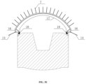
- step 6 with reference to FIG. 3 E , after the second lining structure 17 of the arch covering reaches a design strength, step-slope excavation of middle-layer core soil is carried out.
- a slope of the step-slope excavation should not be greater than 1:0.5, and a horizontal distance of tops of side slopes on two sides should not be less than 3 m.
- step 7 With reference to FIG. 3 F , surrounding rocks on two sides of the middle layer of the station are excavated layer by layer from top to bottom; excavation is carried out to current layer at each step and anchor bolts 7 are driven downwards by 0.5 m, and next step of excavation is carried out after the completion of applying the anchor bolts 7 on two sides and spraying concrete.
- step 8 with reference to FIG. 3 G , after excavation to a design elevation, grouted tunnel wastes 31 are backfilled to a bottom elevation of a medium slab 23 of the second underground floor, and after a foundation bearing capacity required for pushing the shield tunneling machine is met, consequent operation of a medium slab structure 23 and second lining structures 24 for side walls of the first and second underground floors is carried out from bottom to top.
- step 8 should specifically include the following technical contents.
- step 9 after the second lining structure of the medium slab 23 of the second underground floor reaches a design strength, a subgrade is backfilled and a track is laid.
- the platform floor 2 of the subway line A communicates with the interzone tunnel 21 of the left line of the subway line A and the interzone tunnel 22 of the right line of the subway line A, and this meets the condition for pushing the shield tunneling machine through the station, and the shield tunneling machine for the construction of the subway line A may be pushed through the station.
- step 10 with reference to FIG. 3 H and FIG. 3 I , an interzone tunnel of a left line of the subway line B 33 is used as a construction passageway; the platform floor 3 of the subway line B is cyclically excavated, and a temporary steel support 32 is applied timely. After the completion of each round of excavation, the support is removed gradually, and a second lining structure 35 of the third underground floor is applied timely. After the completion of applying the second lining structure 35 of the third underground floor, next round of excavation is carried out.
- step 10 includes the following sub-steps.
- step 10.1 with reference to FIG. 4 A , the interzone tunnel 33 of the left line of the subway line B is used as the construction passageway, and the third underground floor of the station is excavated by a step method. Firstly, a track area 3 A of the left line of the third underground floor is excavated. Before excavation, the grouted tunnel wastes 31 should be removed segmentally to form a vibration insulation layer, and then blasting excavation is carried out. Collapse of the grouted tunnel wastes is prevented and the existing structure is made safe. Excavation is carried out by a cyclical footage.
- the footage is 0.5 m to 1.2 m in a soil layer and unstable rock mass, and is 1 m to 1.5 m in stable rock mass; and when a stable time of an excavation face of the unstable rock mass does not meet preliminary supporting construction, an advanced supporting or grouting reinforcement measure should be taken.
- bolting and shotcreting may be carried out in time and the temporary steel support 32 is erected to support the top slab of the third underground floor.
- step 10.2 with reference to FIG. 4 B , after the excavation of the track area 3 A of the left line of the third underground floor is completed, by entering into the tunnel from a middle position, the middle pilot tunnel 3 B of the third underground floor is excavated also by the step method.
- the grouted tunnel wastes 31 should be removed segmentally to form a vibration insulation layer, and then blasting excavation is carried out. Collapse of the grouted tunnel wastes is prevented and the existing structure is made safe. Excavation is carried out by a cyclical footage.
- the footage is 0.5 m to 1.2 m in a soil layer and unstable rock mass, and is 1 m to 1.5 m in stable rock mass; and when a stable time of an excavation face of the unstable rock mass does not meet preliminary supporting construction, an advanced supporting or grouting reinforcement measure should be taken.
- bolting and shotcreting may be carried out in time and the temporary steel support 32 is erected to support the top slab of the third underground floor. Meanwhile, the second lining structure 35 of the third underground floor for the track area 3 A of the left line of the third underground floor is gradually applied.
- step 10.3 with reference to FIG. 4 C and FIG. 4 D , after the excavation of the middle pilot tunnel 3 B of the third underground floor is completed, tunnels are opened on two sides to excavate a track area 3 C of a right line of the third underground line.
- the grouted tunnel wastes 31 should be removed segmentally to form a vibration insulation layer, and then blasting excavation is carried out. Collapse of the grouted tunnel wastes is prevented and the existing structure is made safe. Excavation is carried out by a cyclical footage.
- the footage is 0.5 m to 1.2 m in a soil layer and unstable rock mass, and is 1 m to 1.5 m in stable rock mass; and when a stable time of an excavation face of the unstable rock mass does not meet preliminary supporting construction, an advanced supporting or grouting reinforcement measure should be taken.
- bolting and shotcreting may be carried out in time and the temporary steel support 32 is erected to support the top slab of the third underground floor.
- the second lining structure 35 of the third underground floor for the track area 3 A of the left line of the third underground floor is completed, and the temporary support 32 of the track area 3 A of the left line of the third underground floor is adjusted to be within the range of the second lining structure.
- step 10.4 with reference to FIG. 4 E , the second lining structures of the middle pilot tunnel 3 B and the track area 3 C of the right line of the third underground floor are subsequently applied.
- the temporary steel support 32 is adjusted to be within the range of the second lining structure.
- step 10.5 after the completion of the second lining structures 35 of the third underground floor on two sides, the middle remaining rock mass 3 D is excavated also by the step method.
- the grouted tunnel wastes 31 should be removed segmentally to form a vibration insulation layer, and then blasting excavation is carried out. Collapse of the grouted tunnel wastes is prevented and the existing structure is made safe.
- Excavation is carried out by a cyclical footage. The footage is 0.5 m to 1.2 m in a soil layer and unstable rock mass, and is 1 m to 1.5 m in stable rock mass; and when a stable time of an excavation face of the unstable rock mass does not meet preliminary supporting construction, an advanced supporting or grouting reinforcement measure should be taken.
- bolting and shotcreting may be carried out in time and the temporary steel support 32 is erected to support the top slab of the third underground floor.
- step 10.6 the remaining second lining structure 35 of the third underground floor is completed, and the temporary steel support 32 is provided.
- step 10.7 with reference to FIG. 4 G , an interzone tunnel 34 of the right line of the subway line B is excavated, and three grid steel frames are erected. A shaft inset is opened to enter the tunnel. C25 concrete is sprayed immediately after excavation to close the surrounding rock; the grid arch frame is erected; the temporary steel support is erected; a mesh reinforcement is bound; and concrete is sprayed.
- a vibration attenuation measure should be taken before excavation. The blasting vibration velocity is strictly controlled within 15 mm/s. When necessary, mechanical excavation is adopted.
- step 11 after the completion of the second lining structure 35 of the third underground floor, remaining interzone ports of the subway line B may be excavated.
- the temporary steel support 32 is gradually removed, permanent concrete columns 6 are applied, and internal structures such as a track area partition wall 38 and a platform transfer passageway 37 are applied.
Landscapes
- Engineering & Computer Science (AREA)
- Mining & Mineral Resources (AREA)
- Architecture (AREA)
- Structural Engineering (AREA)
- General Life Sciences & Earth Sciences (AREA)
- Life Sciences & Earth Sciences (AREA)
- Civil Engineering (AREA)
- Geochemistry & Mineralogy (AREA)
- Geology (AREA)
- Transportation (AREA)
- Mechanical Engineering (AREA)
- Lining And Supports For Tunnels (AREA)
- Underground Structures, Protecting, Testing And Restoring Foundations (AREA)
Abstract
A section of a node of the station is a section with an arch roof and a straight wall of three underground floors, a first underground floor is a station hall floor 1, and a second underground floor is a platform floor 2 of a subway line A and a third underground floor is a platform floor 3 of a subway line B; and directions of the subway line A and the subway line B are orthogonal. Second lining structures of the first and second underground floors are firstly constructed, and after a shield tunneling machine is pushed through the station, the structure of the third underground floor is constructed by a reverse construction method. Thus, the present disclosure is conducive to improving the efficiency of overall construction, guaranteeing timely tunnel construction completion of two lines and hence timely track construction completion and electricity wiring completion.
Description
This application claims priority to Chinese Patent Application No. 202311460950.8 with a filing date of Nov. 6, 2023. The content of the aforementioned application, including any intervening amendments thereto, is incorporated herein by reference.
The present disclosure relates to the technical field of underground engineering constructions, and in particular, to an undercutting-covered excavation semi-reverse construction method of a cross-transfer subway station.
At present, the construction of an urban rail transit system network has become the focus of traffic constructions for many big cities. The networking development of urban rail transit construction has a basic feature of forming an increasing number of transfer nodes at line network intersections. A transfer hub is generally established at such a transfer node with a huge flow of people, allowing passengers to transfer from one line to another line rapidly. Node transfer is one of the most common transfer manners, which generally refers to a transfer manner in which two lines intersect, as compared with parallel transfer. At a position where two lines intersect, an overlapping area of tunnels of the two lines is structured as a whole, which is known as the transfer node. Generally speaking, the section of the transfer node is a three underground-floor large section, where a first underground floor is a station hall, and second and third underground floors are stations of two lines. The construction of a station may easily have an impact on a construction period by an interzone mechanical method. The impact on the construction period of a transfer node is especially serious because the interzone construction periods of two lines need to be taken into account. The worst case is that a shield tunneling machine for a line has been placed at the site of the station of the second underground floor and the transfer node needs to have the condition for pushing the shield tunneling machine through a medium slab as early as possible. In this case, the excavation of the complete section needs to be carried out by a traditional construction method and the shield tunneling machine can be pushed through the station after consequent operation of the second lining structure of the station is carried out from bottom to top (at least the medium slab should be completed and the design strength should be reached). In this case, not only may a high side wall of a three-floor section be excavated, but also the construction period of the station is long, thereby delaying passing of the shield tunneling machine through the station and affecting the penetration of the interzone node.
To this end, the designers of the present disclosure design an undercutting-covered excavation semi-reverse construction method of a cross-transfer subway station by concentrating on researches and by combining the experience and outcomes in the related industry for many years, so as to overcome the above defects.
An objective of the present disclosure is to provide an undercutting-covered excavation semi-reverse construction method of a cross-transfer subway station that can overcome the defects of the prior art, improve the efficiency of overall construction, better shorten the construction period of a whole line, and reduce construction risks.
To achieve the above objective, the present disclosure provides an undercutting-covered excavation semi-reverse construction method of a cross-transfer subway station, where a section of a node of the cross-transfer subway station covers three underground floors, where a first underground floor is a station hall floor, and a second underground floor is a platform floor of a subway line A and a third underground floor is a platform floor of a subway line B; directions of the subway line A and the subway line B are orthogonal; construction is carried out by an arch covering method at the station hall floor and the platform floor of the subway line A; and after a shield tunneling machine for interzone construction of the subway line A is pushed through the station, construction of the platform floor of the subway line B is carried out by covered excavation using a reverse construction method under the section constructed by the arch covering method; the undercutting-covered excavation semi-reverse construction method including the following steps:
-
- step 1: stepwise excavating a left pilot tunnel of an arch; after the completion of excavation, initially spraying 40 mm thick concrete to close surrounding rock, applying anchor bolts, arranging a grid arch frame, erecting a temporary steel arch frame for the left pilot tunnel of the arch, and spraying concrete again to a thickness of 350 mm;
- step 2: stepwise excavating a right pilot tunnel of the arch; after the completion of excavation, initially spraying 40 mm thick concrete immediately to close surrounding rock, applying anchor bolts, arranging a grid arch frame, erecting a temporary steel arch frame, and spraying concrete again to a thickness of 350 mm;
- step 3: excavating remaining surrounding rock of a middle pilot tunnel of the arch of the station and building in a temporary steel arch frame for the middle pilot tunnel of the arch;
- step 4: applying a bottom bedding course, and applying arch foot joists on two sides after the bottom bedding course reaches a strength;
- step 5: removing part of the temporary steel arch frame by means of a spatial effect, laying a waterproofing course, and applying a second lining structure of an arch covering and reserving a side wall construction seam;
- step 6: after the second lining structure of the arch covering reaches a design strength, carrying out step-slope excavation of middle-layer core soil;
- step 7: excavating surrounding rocks on two sides of the middle layer of the station layer by layer from top to bottom; excavating to current layer at each step and driving anchor bolts downwards by 0.5 m, and carrying out next step of excavation after the completion of applying the anchor bolts on two sides and spraying concrete;
- step 8: after excavation to a design elevation, backfilling grouted tunnel wastes to a bottom elevation of a medium slab of the second underground floor, and after a foundation bearing capacity required for pushing the shield tunneling machine is met, carrying out consequent operation of a medium slab structure and second lining structures for side walls of the first and second underground floors from bottom to top;
- step 9: after the second lining structure of the medium slab of the second underground floor reaches a design strength, backfilling a subgrade, laying a track, and pushing the shield tunneling machine for the construction of the subway line A through the station;
- step 10: using an interzone tunnel of a left line of the subway line B as a construction passageway, cyclically excavating the platform floor of the subway line B, and timely applying a temporary steel support; after the completion of each round of excavation, gradually removing the support, timely applying a second lining structure of the third underground floor, and after the completion of applying the second lining structure of the third underground floor, carrying out next round of excavation; and
- step 11: after the completion of the second lining structure of the third underground floor, excavating remaining interzone ports of the subway line B, and applying an internal structure after a shield tunneling machine for the construction of the subway line B is pushed through the station.
In step 1, at least one feet-lock bolt is driven into a position of an anchor foot of the left pilot tunnel of the arch; and in the step 2, at least one feet-lock bolt is driven into a position of an anchor foot of the right pilot tunnel of the arch.
In step 1 and step 2, a footage of each pilot tunnel is greater than or equal to 15 m when the pilot tunnel is excavated.
In step 4, inner ends of the feet-lock bolts 14 driven in the step 1 and step 2 are cast within the arch foot joists, thereby ensuring that the arch foot joists are stable and reliable.
The second lining structure 17 of the arch covering in the step 5 is formed through one step, and L-shaped joints are disposed at joints of the side wall construction seam, respectively.
A slope of the step-slope excavation in the step 6 is not greater than 1:0.5, and a horizontal distance of tops of side slopes on two sides is not less than 3 m.
The grouted tunnel wastes backfilled in the step 8 are uniformly roll-compacted with a compactness of greater than or equal to 93%; during roll-compacting, each layer is 25 cm to 30 cm thick; the second lining structures and permanent concrete columns of the first and second underground floors are cast below the medium slab of the second underground floor by not less than 500 mm; a ratio of reserved joints of reinforcements at a same section is not greater than 50%.
Step 10 includes the following sub-steps:
-
- step 10.1: using the interzone tunnel of the left line of the subway line B as the construction passageway, firstly excavating a track area of the left line of the third underground floor using a step method, carrying out excavation by a cyclical footage, and after the completion of excavation of the footage per round, carrying out bolting and shotcreting in time and erecting the temporary steel support to support a top slab of the third underground floor;
- step 10.2: entering into the tunnel from a middle position, and excavating the middle pilot tunnel of the third underground floor; carrying out excavation by a cyclical footage also by the step method, and after the completion of excavation of the footage per round, carrying out bolting and shotcreting in time and erecting the temporary steel support to support the top slab of the third underground floor; meanwhile, gradually applying the second lining structure of the third underground floor for the track area of the left line of the third underground floor;
- step 10.3: opening tunnels on two sides to excavate a track area of a right line of the third underground line; carrying out excavation by a cyclical footage, and after the completion of excavation of the footage per round, carrying out bolting and shotcreting in time and erecting the temporary steel support to support the top slab of the third underground floor; completing the second lining structure of the third underground floor for the track area of the left line of the third underground floor, and adjusting the temporary support of the track area of the left line of the third underground floor to be within the range of the second lining structure;
- step 10.4: subsequently applying the second lining structures of the middle pilot tunnel and the track area of the right line of the third underground floor, and after the completion of application and closure of the second lining structure of the third underground floor, adjusting the temporary steel support to be within the range of the second lining structure;
- step 10.5: excavating remaining rock mass in the middle, carrying out excavation by a cyclical footage also by the step method, and after the completion of excavation of the footage per round, carrying out bolting and shotcreting in time and erecting the temporary steel support to support the top slab of the third underground floor;
- step 10.6: completing the remaining second lining structure of the third underground floor, and providing the temporary steel support; and
- step 10.7: excavating an interzone tunnel of the right line of the subway line B, erecting three grid steel frames, spraying C25 concrete immediately after excavation to close the surrounding rock, erecting the grid arch frame, erecting the temporary steel support, binding a mesh reinforcement, and spraying concrete.
In steps 10.1, 10.2, 10.3, and 10.5, the footage is 0.5 m to 1.2 m in a soil layer and unstable rock mass, and is 1 m to 1.5 m in stable rock mass; and when a stable time of an excavation face of the unstable rock mass does not meet preliminary supporting construction, an advanced supporting or grouting reinforcement measure is taken.
As can be known from the above contents, the undercutting-covered excavation semi-reverse construction method of a cross-transfer subway station of the present disclosure has the following effects:
-
- 1. By the method of firstly constructing the second lining structures of the first and second underground floors and carrying out reverse construction of the structure of the third underground floor after pushing the shield tunneling machine through the station, the efficiency of overall construction can be improved, guaranteeing timely tunnel construction completion of two lines and hence timely track construction completion and electricity wiring completion, so that the subway lines can be opened to traffic as early as possible.
- 2. Compared with a traditional method of carrying out consequent operation of a structure after the completion of excavation of an overall section, the construction period may be shortened by at least three months.
- 3. Moreover, compared with excavation of the entire three-floor section by using a double-side heading method, this method reduces risks induced by a high side wall. Therefore, this method is a method that can improve the construction efficiency, shorten the construction period of the whole line, and reduce the construction risks to the utmost extent on the basis of guaranteeing safety.
The detailed contents of the present disclosure may be obtained from the following description and the accompanying drawings.
-
- 1—station hall floor; 2—platform floor of subway line A; 3—platform floor of subway line B; 6—permanent concrete column; 7—anchor bolt; 11—left pilot tunnel of arch; 12—right pilot tunnel of arch; 13—middle pilot tunnel of arch; 14—feet-lock bolt; 15—temporary steel arch frame; 16—arch foot joist; 17—second lining structure of arch covering; 18—L-shaped joint; 19—medium slab of first underground floor; 21—interzone tunnel of left line of subway line A; 22—interzone tunnel of right line of subway line A; 23—medium slab of second underground floor; 24—second lining structures for side walls of first and second underground floors; 31—grouted tunnel wastes; 32—temporary steel support; 33—interzone tunnel of left line of subway line B; 34—interzone tunnel of right line of subway line B; 35—second lining structure of third underground floor; 36—port ring beam; 37—transfer passageway of third underground floor; 38—partition wall of track area; 3A—track area of left line of third underground floor; 3B—middle pilot tunnel of third underground floor; 3C—track area of right line of third underground floor; and 3D—middle remaining rock mass of third underground floor.
With reference to FIG. 1 and FIG. 2 , FIG. 1 and FIG. 2 show a form of a node of the cross-transfer subway station in an undercutting-covered excavation semi-reverse construction method of a cross-transfer subway station of the present disclosure. A section of the node of the station is a section with an arch roof and a straight wall of three underground floors, where a first underground floor is a station hall floor 1, and a second underground floor is a platform floor 2 of a subway line A and a third underground floor is a platform floor 3 of a subway line B; and directions of the subway line A and the subway line B are orthogonal. The transfer node may be a cross transfer, T-shaped transfer, or L-shaped transfer node. The transfer node will not be limited here as long as the transfer node is in the form described in the present disclosure.
According to the undercutting-covered excavation semi-reverse construction method of a cross-transfer subway station, construction is carried out by an arch covering method at the station hall floor 1 and the platform floor 2 of the subway line A; and after a shield tunneling machine for interzone construction of the subway line A is pushed through the station, construction of the platform floor 3 of the subway line B is carried out by covered excavation using a reverse construction method under the section constructed by the arch covering method. Specifically, the present disclosure may include the following steps.
In step 1, with reference to FIG. 3A , a left pilot tunnel 11 of an arch is stepwise excavated; after the completion of excavation, 40 mm thick concrete is initially sprayed immediately to close surrounding rock; anchor bolts 7 are applied at the top of the left pilot tunnel 11 of the arch; a grid arch frame is arranged; a temporary steel arch frame 15 for the left pilot tunnel 11 of the arch is erected, a mesh reinforcement is bound, and concrete is sprayed again to a thickness of 350 mm. To ensure stable preliminary supporting, at least one feet-lock bolt 14 is driven into a position of an anchor foot of the left pilot tunnel 11 of the arch.
In step 2, with reference to FIG. 3B , a right pilot tunnel 12 of the arch is stepwise excavated; after the completion of excavation, 40 mm thick concrete is initially sprayed immediately to close surrounding rock; anchor bolts 7 are applied to the right pilot tunnel 12 of the arch; a grid arch frame is arranged; a temporary steel arch frame 15 for the right pilot tunnel 12 of the arch is erected, a mesh reinforcement is bound, and concrete is sprayed again to a thickness of 350 mm. To ensure stable preliminary supporting, at least one feet-lock bolt 14 is driven into a position of an anchor foot of the right pilot tunnel 12 of the arch.
In step 1 and step 2, when the pilot tunnels are excavated, blasting has a certain impact on adjacent pilot tunnels, and it is required that a footage of each pilot tunnel during construction should be greater than or equal to 15 m. When concrete is sprayed, operation should be carried out in strict accordance with requirements of a wet spraying process. The sprayed concrete should be dense and flat without cracking, peeling, missing spraying, reinforcement missing, hollowing, water leakage, and the like. The operation of spraying concrete should be orderly carried out from bottom to top in segments, in slices, and in layers.
In step 3, with reference to FIG. 3C , remaining surrounding rock of a middle pilot tunnel 13 of the arch of the station is excavated. Note that not less than 1 m thick rock mass should be reserved. A temporary steel arch frame 15 for the middle pilot tunnel 13 of the arch is built in. Preferably, blasting should be controlled and the middle temporary steel arch support is protected.
In step 4, with reference to FIG. 3D , a bottom bedding course is applied, and arch foot joists 16 on two sides are applied after the bottom bedding course reaches a strength. Preferably, inner ends of the feet-lock bolts 14 driven in the step 1 and step 2 are cast within the arch foot joists, thereby ensuring that the arch foot joists are stable and reliable.
In step 5: part of the temporary steel arch frame 15 is removed by means of a spatial effect (a length by which the support is removed each time is not more than 6 m); a waterproofing course is laid; and a second lining structure 17 of an arch covering is applied and a side wall construction seam is reserved. Meanwhile, monitoring and measurement are strengthened such that a length of a segment is adjusted timely.
Step 5 specifically includes the following technical contents.
-
- 1. The
second lining structure 17 of the arch covering should be formed through one step and should not be cast in steps. - 2. L-shaped
joints 18 are disposed at joints of the side wall construction seam, respectively. The construction seam is treated using a filling method: when concrete is poured at bottom by a distance of 100 mm to 150 mm from the construction seam, laitance is removed, and shrinkage-free concrete of a same grade is used for filling.
- 1. The
In step 6, with reference to FIG. 3E , after the second lining structure 17 of the arch covering reaches a design strength, step-slope excavation of middle-layer core soil is carried out. Preferably, a slope of the step-slope excavation should not be greater than 1:0.5, and a horizontal distance of tops of side slopes on two sides should not be less than 3 m.
In step 7, with reference to FIG. 3F , surrounding rocks on two sides of the middle layer of the station are excavated layer by layer from top to bottom; excavation is carried out to current layer at each step and anchor bolts 7 are driven downwards by 0.5 m, and next step of excavation is carried out after the completion of applying the anchor bolts 7 on two sides and spraying concrete.
In step 8: with reference to FIG. 3G , after excavation to a design elevation, grouted tunnel wastes 31 are backfilled to a bottom elevation of a medium slab 23 of the second underground floor, and after a foundation bearing capacity required for pushing the shield tunneling machine is met, consequent operation of a medium slab structure 23 and second lining structures 24 for side walls of the first and second underground floors is carried out from bottom to top.
In particular, step 8 should specifically include the following technical contents.
-
- 1. The grouted tunnel wastes 31 backfilled should be uniformly roll-compacted, avoiding nonuniform bearing of stress by the structure. The backfilled tunnel wastes should be tamped in layers. A compactness of the roll-compacted tunnel wastes is greater than or equal to 93%, and during roll-compacting, each layer is 25 cm to 30 cm thick. Soil with good water permeability and poor soil quality, such as sandy soil and miscellaneous fill, should not be used.
- 2. Since the third underground floor is constructed using the reverse construction method, nodes should be reserved for the
second lining structures 24 and permanentconcrete columns 6 of the first and second underground floors. Thesecond lining structures 24 and the permanentconcrete columns 6 of the first and second underground floors are cast below themedium slab 23 of the second underground floor by not less than 500 mm; and a ratio of reserved joints of reinforcements at a same section is not greater than 50%. The reserved reinforcements are protected.
In step 9, after the second lining structure of the medium slab 23 of the second underground floor reaches a design strength, a subgrade is backfilled and a track is laid. At this time, the platform floor 2 of the subway line A communicates with the interzone tunnel 21 of the left line of the subway line A and the interzone tunnel 22 of the right line of the subway line A, and this meets the condition for pushing the shield tunneling machine through the station, and the shield tunneling machine for the construction of the subway line A may be pushed through the station.
In step 10, with reference to FIG. 3H and FIG. 3I , an interzone tunnel of a left line of the subway line B 33 is used as a construction passageway; the platform floor 3 of the subway line B is cyclically excavated, and a temporary steel support 32 is applied timely. After the completion of each round of excavation, the support is removed gradually, and a second lining structure 35 of the third underground floor is applied timely. After the completion of applying the second lining structure 35 of the third underground floor, next round of excavation is carried out.
The following should be noted in the step 10.
-
- 1. The stability of the top grouted tunnel wastes 31 should be noted during excavation, avoiding collapse of the grouted tunnel wastes 31. A vibration insulation layer is formed after the completion of partitioned removal of the grouted tunnel wastes 31, and then blasting excavation is carried out.
- 2. For blasting, a blasting design should be made. Smooth blasting is recommended, and relevant parameters should be corrected timely according to a blasting effect. Blasting parameters should be determined after a trial blast on the spot according to the principles of shallow holes, dense distribution, weak blasting, and progressive blasting. In the blasting design, the influence of vibration on adjacent tunnels and buildings and structures in the proximity thereof is mainly considered to ensure construction safety.
- 3. Tunnel excavation should be carried out in strict accordance with the policies of short footage, weak blasting, strong support, and fast closure, reducing disturbance for the surrounding rock and reducing the influence of vibration on surrounding buildings. A vibration velocity of blasting for surrounding buildings should be controlled within 15 mm/s; otherwise, a machine should be used for carrying out excavation to guarantee the safety and stability of the surrounding buildings.
Specifically, step 10 includes the following sub-steps.
In step 10.1, with reference to FIG. 4A , the interzone tunnel 33 of the left line of the subway line B is used as the construction passageway, and the third underground floor of the station is excavated by a step method. Firstly, a track area 3A of the left line of the third underground floor is excavated. Before excavation, the grouted tunnel wastes 31 should be removed segmentally to form a vibration insulation layer, and then blasting excavation is carried out. Collapse of the grouted tunnel wastes is prevented and the existing structure is made safe. Excavation is carried out by a cyclical footage. The footage is 0.5 m to 1.2 m in a soil layer and unstable rock mass, and is 1 m to 1.5 m in stable rock mass; and when a stable time of an excavation face of the unstable rock mass does not meet preliminary supporting construction, an advanced supporting or grouting reinforcement measure should be taken. After the completion of excavation of the footage per round, bolting and shotcreting may be carried out in time and the temporary steel support 32 is erected to support the top slab of the third underground floor.
In step 10.2, with reference to FIG. 4B , after the excavation of the track area 3A of the left line of the third underground floor is completed, by entering into the tunnel from a middle position, the middle pilot tunnel 3B of the third underground floor is excavated also by the step method. Before excavation, the grouted tunnel wastes 31 should be removed segmentally to form a vibration insulation layer, and then blasting excavation is carried out. Collapse of the grouted tunnel wastes is prevented and the existing structure is made safe. Excavation is carried out by a cyclical footage. The footage is 0.5 m to 1.2 m in a soil layer and unstable rock mass, and is 1 m to 1.5 m in stable rock mass; and when a stable time of an excavation face of the unstable rock mass does not meet preliminary supporting construction, an advanced supporting or grouting reinforcement measure should be taken. After the completion of excavation of the footage per round, bolting and shotcreting may be carried out in time and the temporary steel support 32 is erected to support the top slab of the third underground floor. Meanwhile, the second lining structure 35 of the third underground floor for the track area 3A of the left line of the third underground floor is gradually applied.
In step 10.3, with reference to FIG. 4C and FIG. 4D , after the excavation of the middle pilot tunnel 3B of the third underground floor is completed, tunnels are opened on two sides to excavate a track area 3C of a right line of the third underground line. Likewise, before excavation, the grouted tunnel wastes 31 should be removed segmentally to form a vibration insulation layer, and then blasting excavation is carried out. Collapse of the grouted tunnel wastes is prevented and the existing structure is made safe. Excavation is carried out by a cyclical footage. The footage is 0.5 m to 1.2 m in a soil layer and unstable rock mass, and is 1 m to 1.5 m in stable rock mass; and when a stable time of an excavation face of the unstable rock mass does not meet preliminary supporting construction, an advanced supporting or grouting reinforcement measure should be taken. After the completion of excavation of the footage per round, bolting and shotcreting may be carried out in time and the temporary steel support 32 is erected to support the top slab of the third underground floor. The second lining structure 35 of the third underground floor for the track area 3A of the left line of the third underground floor is completed, and the temporary support 32 of the track area 3A of the left line of the third underground floor is adjusted to be within the range of the second lining structure.
In step 10.4, with reference to FIG. 4E , the second lining structures of the middle pilot tunnel 3B and the track area 3C of the right line of the third underground floor are subsequently applied. After the completion of application and closure of the second lining structures 35 of the third underground floor on both flanks of H-shape, the temporary steel support 32 is adjusted to be within the range of the second lining structure.
In step 10.5, with reference to FIG. 4F , after the completion of the second lining structures 35 of the third underground floor on two sides, the middle remaining rock mass 3D is excavated also by the step method. Before excavation, the grouted tunnel wastes 31 should be removed segmentally to form a vibration insulation layer, and then blasting excavation is carried out. Collapse of the grouted tunnel wastes is prevented and the existing structure is made safe. Excavation is carried out by a cyclical footage. The footage is 0.5 m to 1.2 m in a soil layer and unstable rock mass, and is 1 m to 1.5 m in stable rock mass; and when a stable time of an excavation face of the unstable rock mass does not meet preliminary supporting construction, an advanced supporting or grouting reinforcement measure should be taken. After the completion of excavation of the footage per round, bolting and shotcreting may be carried out in time and the temporary steel support 32 is erected to support the top slab of the third underground floor.
In step 10.6, the remaining second lining structure 35 of the third underground floor is completed, and the temporary steel support 32 is provided.
In step 10.7, with reference to FIG. 4G , an interzone tunnel 34 of the right line of the subway line B is excavated, and three grid steel frames are erected. A shaft inset is opened to enter the tunnel. C25 concrete is sprayed immediately after excavation to close the surrounding rock; the grid arch frame is erected; the temporary steel support is erected; a mesh reinforcement is bound; and concrete is sprayed. To guarantee the safety of the second lining structure of the station, a vibration attenuation measure should be taken before excavation. The blasting vibration velocity is strictly controlled within 15 mm/s. When necessary, mechanical excavation is adopted.
In step 11, with reference to FIG. 4H , after the completion of the second lining structure 35 of the third underground floor, remaining interzone ports of the subway line B may be excavated. After a shield tunneling machine for the construction of the subway line B is pushed through the station, the temporary steel support 32 is gradually removed, permanent concrete columns 6 are applied, and internal structures such as a track area partition wall 38 and a platform transfer passageway 37 are applied.
As can be seen, the present disclosure involves the following key steps and the following advantages:
-
- 1. The undercutting-covered excavation semi-reverse construction method is used. The section of the transfer node provided in the present disclosure is in the form of three underground floors. The first underground floor and the second underground floor are undercut by the arch covering method. After the backfilled grouted tunnel wastes have a sufficient foundation bearing capacity and the second lining structure of the medium slab of the second underground floor reaches the design strength, the shield tunneling machine for the two lines may be pushed through the station. After the shield tunneling machine is pushed through the station, the structure of the third underground floor is constructed by the reverse construction method. Thus, the construction efficiency can be improved to the utmost extent and the construction period can be saved, guaranteeing that the construction of the interzone node is preferably completed as early as possible.
- 2. After excavation to the design elevation, the grouted tunnel wastes are backfilled to the bottom elevation of the medium slab. The grouted tunnel wastes backfilled should be uniformly roll-compacted, avoiding nonuniform bearing of stress by the structure. The backfilled tunnel wastes should be tamped in layers. A compactness of the roll-compacted tunnel wastes is greater than or equal to 93%, and during roll-compacting, each layer is 25 cm to 30 cm thick. Soil with good water permeability and poor soil quality, such as sandy soil and miscellaneous fill, should not be used. Thus, the foundation bearing capacity below the medium slab of the second underground floor may be effectively improved and the requirement of flatness is met. Nonuniform stress on the medium slab structure of the second underground floor or structural damage caused by insufficient bearing capacity below when the shield tunneling machine is pushed through the station are prevented.
Apparently, the foregoing descriptions and contents are merely exemplary and not intended to limit the disclosures, application, or use of the present disclosure. Although the embodiments have been described above and in the accompanying drawings, the present disclosure does not limit particular examples that are illustrated in the accompanying drawings and described in the embodiments as the teaching of the currently considered best mode to carry out the present disclosure. The scope of the present disclosure will include any embodiment falling within the foregoing description and the appended claims.
Claims (9)
1. An undercutting-covered excavation semi-reverse construction method of a cross-transfer subway station, wherein a section of a node of the cross-transfer subway station covers three underground floors, wherein a first underground floor is a station hall floor, and a second underground floor is a platform floor of a subway line A and a third underground floor is a platform floor of a subway line B; directions of the subway line A and the subway line B are orthogonal; construction is carried out by an arch covering method at the station hall floor and the platform floor of the subway line A; and after a shield tunneling machine for interzone construction of the subway line A is pushed through the station, construction of the platform floor of the subway line B is carried out by covered excavation using a reverse construction method under the section constructed by the arch covering method; the undercutting-covered excavation semi-reverse construction method comprises the following steps:
step 1: stepwise excavating a left pilot tunnel of an arch; after the completion of excavation, initially spraying 40 mm thick concrete to close surrounding rock, applying anchor bolts, arranging a grid arch frame, erecting a temporary steel arch frame for the left pilot tunnel of the arch, and spraying concrete again to a thickness of 350 mm;
step 2: stepwise excavating a right pilot tunnel of the arch; after the completion of excavation, initially spraying 40 mm thick concrete immediately to close surrounding rock, applying anchor bolts, arranging a grid arch frame, erecting a temporary steel arch frame, and spraying concrete again to a thickness of 350 mm;
step 3: excavating remaining surrounding rock of a middle pilot tunnel of the arch of the station and building in a temporary steel arch frame for the middle pilot tunnel of the arch;
step 4: applying a bottom bedding course, and applying arch foot joists on two sides after the bottom bedding course reaches a strength;
step 5: removing part of the temporary steel arch frame by means of a spatial effect, laying a waterproofing course, and applying a second lining structure of an arch covering and reserving a side wall construction seam;
step 6: after the second lining structure of the arch covering reaches a design strength, carrying out step-slope excavation of middle-layer core soil;
step 7: excavating surrounding rocks on two sides of the middle layer of the station layer by layer from top to bottom; excavating to current layer at each step and driving anchor bolts downwards by 0.5 m, and carrying out next step of excavation after the completion of applying the anchor bolts on two sides and spraying concrete;
step 8: after excavation to a design elevation, backfilling grouted tunnel wastes to a bottom elevation of a medium slab of the second underground floor, and after a foundation bearing capacity required for pushing the shield tunneling machine is met, carrying out consequent operation of a medium slab structure and second lining structures for side walls of the first and second underground floors from bottom to top;
step 9: after the second lining structure of the medium slab of the second underground floor reaches a design strength, backfilling a subgrade, laying a track, and pushing the shield tunneling machine for the construction of the subway line A through the station;
step 10: using an interzone tunnel of a left line of the subway line B as a construction passageway, cyclically excavating the platform floor of the subway line B, and timely applying a temporary steel support; after the completion of each round of excavation, gradually removing the support, timely applying a second lining structure of the third underground floor, and after the completion of applying the second lining structure of the third underground floor, carrying out next round of excavation; and
step 11: after the completion of the second lining structure of the third underground floor, excavating remaining interzone ports of the subway line B, and applying an internal structure after a shield tunneling machine for the construction of the subway line B is pushed through the station.
2. The undercutting-covered excavation semi-reverse construction method of the cross-transfer subway station according to claim 1 , wherein in the step 1, at least one feet-lock bolt is driven into a position of an anchor foot of the left pilot tunnel of the arch; and in the step 2, at least one feet-lock bolt is driven into a position of an anchor foot of the right pilot tunnel of the arch.
3. The undercutting-covered excavation semi-reverse construction method of the cross-transfer subway station according to claim 1 , wherein in the step 1 and step 2, a footage of each pilot tunnel is greater than or equal to 15 m when the pilot tunnel is excavated.
4. The undercutting-covered excavation semi-reverse construction method of the cross-transfer subway station according to claim 2 , wherein in the step 4, inner ends of the feet-lock bolts driven in the step 1 and step 2 are cast within the arch foot joists, thereby ensuring that the arch foot joists are stable and reliable.
5. The undercutting-covered excavation semi-reverse construction method of the cross-transfer subway station according to claim 1 , wherein the second lining structure of the arch covering in the step 5 is formed through one step, and L-shaped joints are disposed at joints of the side wall construction seam, respectively.
6. The undercutting-covered excavation semi-reverse construction method of the cross-transfer subway station according to claim 1 , wherein a slope of the step-slope excavation in the step 6 is not greater than 1:0.5, and a horizontal distance of tops of side slopes on two sides is not less than 3 m.
7. The undercutting-covered excavation semi-reverse construction method of the cross-transfer subway station according to claim 1 , wherein the grouted tunnel wastes backfilled in the step 8 are uniformly roll-compacted with a compactness of greater than or equal to 93%; during roll-compacting, each layer is 25 cm to 30 cm thick; the second lining structures and permanent concrete columns of the first and second underground floors are cast below the medium slab of the second underground floor by not less than 500 mm; a ratio of reserved joints of reinforcements at a same section is not greater than 50%.
8. The undercutting-covered excavation semi-reverse construction method of the cross-transfer subway station according to claim 1 , wherein the step 10 comprises the following sub-steps:
step 10.1: using the interzone tunnel of the left line of the subway line B as the construction passageway, firstly excavating a track area of the left line of the third underground floor using a step method, carrying out excavation by a cyclical footage, and after the completion of excavation of the footage per round, carrying out bolting and shotcreting in time and erecting the temporary steel support to support a top slab of the third underground floor;
step 10.2: entering into the tunnel from a middle position, and excavating the middle pilot tunnel of the third underground floor; carrying out excavation by cyclic footages also by the step method, and after the completion of excavation of the footage per round, carrying out bolting and shotcreting in time and erecting the temporary steel support to support the top slab of the third underground floor; meanwhile, gradually applying the second lining structure of the third underground floor for the track area of the left line of the third underground floor;
step 10.3: opening tunnels on two sides to excavate a track area of a right line of the third underground line; carrying out excavation by a cyclical footage, and after the completion of excavation of the footage per round, carrying out bolting and shotcreting in time and erecting the temporary steel support to support the top slab of the third underground floor; completing the second lining structure of the third underground floor for the track area of the left line of the third underground floor, and adjusting the temporary support of the track area of the left line of the third underground floor to be within the range of the second lining structure;
step 10.4: subsequently applying the second lining structures of the middle pilot tunnel and the track area of the right line of the third underground floor, and after the completion of application and closure of the second lining structure of the third underground floor, adjusting the temporary steel support to be within the range of the second lining structure;
step 10.5: excavating remaining rock mass in the middle, carrying out excavation by a cyclical footage also by the step method, and after the completion of excavation of the footage per round, carrying out bolting and shotcreting in time and erecting the temporary steel support to support the top slab of the third underground floor;
step 10.6: completing the remaining second lining structure of the third underground floor, and providing the temporary steel support; and
step 10.7: excavating an interzone tunnel of the right line of the subway line B, erecting three grid steel frames, spraying C25 concrete immediately after excavation to close the surrounding rock, erecting the grid arch frame, erecting the temporary steel support, binding a mesh reinforcement, and spraying concrete.
9. The undercutting-covered excavation semi-reverse construction method of the cross-transfer subway station according to claim 8 , wherein in steps 10.1, 10.2, 10.3, and 10.5, the cyclical footage is 0.5 m to 1.2 m in a soil layer and unstable rock mass, and is 1 m to 1.5 m in stable rock mass; and when a stable time of an excavation face of the unstable rock mass does not meet preliminary supporting construction, an advanced supporting or grouting reinforcement measure is taken.
Applications Claiming Priority (2)
| Application Number | Priority Date | Filing Date | Title |
|---|---|---|---|
| CN202311460950.8 | 2023-11-06 | ||
| CN202311460950.8A CN117189189B (en) | 2023-11-06 | 2023-11-06 | Dark-cover excavation half reverse construction method for cross transfer subway station |
Publications (1)
| Publication Number | Publication Date |
|---|---|
| US12084971B1 true US12084971B1 (en) | 2024-09-10 |
Family
ID=88992735
Family Applications (1)
| Application Number | Title | Priority Date | Filing Date |
|---|---|---|---|
| US18/673,287 Active US12084971B1 (en) | 2023-11-06 | 2024-05-23 | Undercutting-covered excavation semi-reverse construction method of cross-transfer subway station |
Country Status (3)
| Country | Link |
|---|---|
| US (1) | US12084971B1 (en) |
| JP (1) | JP7624570B1 (en) |
| CN (1) | CN117189189B (en) |
Cited By (6)
| Publication number | Priority date | Publication date | Assignee | Title |
|---|---|---|---|---|
| US20240368991A1 (en) * | 2022-03-30 | 2024-11-07 | Chang'an University | Tunnel constraint anchor cable and method for improving stability of initial support structure |
| CN119466821A (en) * | 2024-12-12 | 2025-02-18 | 上海隧道工程有限公司 | A method for expanding the existing subway station by adding floors downwards using a non-closed bundled tube curtain |
| CN119712120A (en) * | 2024-11-28 | 2025-03-28 | 中建五局土木工程有限公司 | Excavation construction method for in-situ partition reservation of surrounding rock of large-section underwater tunnel in weak broken surrounding rock |
| CN120211783A (en) * | 2025-05-26 | 2025-06-27 | 中铁十六局集团有限公司 | Tunnel construction method for extra-large-span flat tunnel passing under the runway |
| US12523150B1 (en) * | 2024-11-21 | 2026-01-13 | China University of Mining And Technology-Beijing | Excavation compensation method for tunnelling in deep rock engineering |
| WO2026060993A1 (en) * | 2024-09-19 | 2026-03-26 | 中建三局集团(浙江)有限公司 | Construction method for non-reserved rail transit interface of operating subway station |
Families Citing this family (1)
| Publication number | Priority date | Publication date | Assignee | Title |
|---|---|---|---|---|
| CN118424056A (en) * | 2024-06-03 | 2024-08-02 | 北京城建设计发展集团股份有限公司 | Blasting Control Construction Method for Rock Stratum Arch Covering Station |
Citations (10)
| Publication number | Priority date | Publication date | Assignee | Title |
|---|---|---|---|---|
| US3616650A (en) * | 1969-01-27 | 1971-11-02 | Kunz Alfred & Co | Method and apparatus for constructing subterranean structures |
| US3916630A (en) * | 1973-04-27 | 1975-11-04 | Gewerk Eisenhuette Westfalia | Tunneling methods and apparatus |
| US4603910A (en) | 1983-03-23 | 1986-08-05 | Jcc Construction Company Ab | Method of blasting rock caverns with large cross-sectional area |
| US4929123A (en) * | 1988-03-16 | 1990-05-29 | Pietro Lunardi | Method for building large span tunnels by means of a cellular arch |
| US5104259A (en) | 1989-12-06 | 1992-04-14 | Kurt Svensson Gravmaskiner Aktiebolag | Method for excavating rock cavities |
| US5118220A (en) | 1988-06-15 | 1992-06-02 | Kabushiki Kaisha Kematsu Seisakusho | Method of building underground cavern and tunneling machine |
| US5199817A (en) * | 1991-09-04 | 1993-04-06 | Mayreder Consult Of The United States, Inc. | Process of providing an elongate underground cavity |
| CN106337686A (en) * | 2015-07-13 | 2017-01-18 | 中铁第六勘察设计院集团有限公司 | Rock stratum underground excavation three-story subway station umbrella cover structure and construction method thereof |
| US10280749B2 (en) * | 2017-09-05 | 2019-05-07 | Chang'an Univeristy | Method for deformation control of large-span tunnel in chlorite schist stratum |
| US20200263543A1 (en) * | 2019-02-20 | 2020-08-20 | Dsi Tunneling Llc | Tunnel support system and method |
Family Cites Families (15)
| Publication number | Priority date | Publication date | Assignee | Title |
|---|---|---|---|---|
| RU2131960C1 (en) * | 1996-08-15 | 1999-06-20 | Акционерное общество открытого типа Научно-исследовательский проектно-изыскательский институт "Ленметрогипротранс" | Double-level single-vault transfer station unit of deep subway |
| JP2003269079A (en) | 2002-03-15 | 2003-09-25 | Daiho Constr Co Ltd | How to build a tunnel |
| WO2013147652A2 (en) * | 2012-03-30 | 2013-10-03 | Общество с ограниченной ответственностью "Инженерное бюро Юркевича" | Metro station and method for constructing same |
| CN102943678B (en) * | 2012-11-28 | 2015-01-07 | 北京市市政工程设计研究总院有限公司 | Arched subway station old and new building connection structure and construction method |
| CN104196537A (en) * | 2014-08-26 | 2014-12-10 | 广东省建筑工程机械施工有限公司 | Construction method of three parallel metro tunnels with ultra-small clear distance |
| CN105041349B (en) * | 2015-07-26 | 2017-07-14 | 北京工业大学 | A kind of excavating construction method that station is digged on the basis of Subway Tunnel shield tunnel |
| CN108266209A (en) | 2017-12-29 | 2018-07-10 | 中铁隆工程集团有限公司 | A kind of big ledge method in large section subway station excavates the rapid constructing method of lower part |
| CN108412500A (en) | 2018-02-08 | 2018-08-17 | 中铁二院工程集团有限责任公司 | Mountainous City Underground Subway Station vented construction and its construction method |
| CN108843338B (en) * | 2018-06-27 | 2024-10-15 | 北京市政路桥股份有限公司 | Integrated excavation construction method for converting shaft construction channel into large-section tunnel |
| CN110735656B (en) * | 2019-09-26 | 2021-12-24 | 重庆市轨道交通设计研究院有限责任公司 | Method for reversely building underground excavation station tunnel with ultra-large section in soft rock area based on arch cover method |
| CN217681731U (en) | 2022-01-04 | 2022-10-28 | 北京市市政工程设计研究总院有限公司 | Air shaft duct for breaking shield tunnel segment mine construction interval |
| CN114991204A (en) * | 2022-05-11 | 2022-09-02 | 中铁第六勘察设计院集团有限公司 | Rapid combination construction method for arch shell of pillarless hall station |
| CN115653649A (en) * | 2022-12-27 | 2023-01-31 | 中国铁路设计集团有限公司 | Construction method for multi-pilot tunnel subsection step excavation single-span support underground excavation large-section station |
| CN116145729B (en) * | 2023-04-23 | 2023-07-28 | 北京城建设计发展集团股份有限公司 | Subway Delamination Station Structure and Construction Method in Sea-Land Connection Area |
| JP3243682U (en) | 2023-07-14 | 2023-09-11 | 中鉄(広州)投資発展有限公司 | Subway large span tunnel main structure |
-
2023
- 2023-11-06 CN CN202311460950.8A patent/CN117189189B/en active Active
-
2024
- 2024-05-20 JP JP2024081560A patent/JP7624570B1/en active Active
- 2024-05-23 US US18/673,287 patent/US12084971B1/en active Active
Patent Citations (10)
| Publication number | Priority date | Publication date | Assignee | Title |
|---|---|---|---|---|
| US3616650A (en) * | 1969-01-27 | 1971-11-02 | Kunz Alfred & Co | Method and apparatus for constructing subterranean structures |
| US3916630A (en) * | 1973-04-27 | 1975-11-04 | Gewerk Eisenhuette Westfalia | Tunneling methods and apparatus |
| US4603910A (en) | 1983-03-23 | 1986-08-05 | Jcc Construction Company Ab | Method of blasting rock caverns with large cross-sectional area |
| US4929123A (en) * | 1988-03-16 | 1990-05-29 | Pietro Lunardi | Method for building large span tunnels by means of a cellular arch |
| US5118220A (en) | 1988-06-15 | 1992-06-02 | Kabushiki Kaisha Kematsu Seisakusho | Method of building underground cavern and tunneling machine |
| US5104259A (en) | 1989-12-06 | 1992-04-14 | Kurt Svensson Gravmaskiner Aktiebolag | Method for excavating rock cavities |
| US5199817A (en) * | 1991-09-04 | 1993-04-06 | Mayreder Consult Of The United States, Inc. | Process of providing an elongate underground cavity |
| CN106337686A (en) * | 2015-07-13 | 2017-01-18 | 中铁第六勘察设计院集团有限公司 | Rock stratum underground excavation three-story subway station umbrella cover structure and construction method thereof |
| US10280749B2 (en) * | 2017-09-05 | 2019-05-07 | Chang'an Univeristy | Method for deformation control of large-span tunnel in chlorite schist stratum |
| US20200263543A1 (en) * | 2019-02-20 | 2020-08-20 | Dsi Tunneling Llc | Tunnel support system and method |
Cited By (6)
| Publication number | Priority date | Publication date | Assignee | Title |
|---|---|---|---|---|
| US20240368991A1 (en) * | 2022-03-30 | 2024-11-07 | Chang'an University | Tunnel constraint anchor cable and method for improving stability of initial support structure |
| WO2026060993A1 (en) * | 2024-09-19 | 2026-03-26 | 中建三局集团(浙江)有限公司 | Construction method for non-reserved rail transit interface of operating subway station |
| US12523150B1 (en) * | 2024-11-21 | 2026-01-13 | China University of Mining And Technology-Beijing | Excavation compensation method for tunnelling in deep rock engineering |
| CN119712120A (en) * | 2024-11-28 | 2025-03-28 | 中建五局土木工程有限公司 | Excavation construction method for in-situ partition reservation of surrounding rock of large-section underwater tunnel in weak broken surrounding rock |
| CN119466821A (en) * | 2024-12-12 | 2025-02-18 | 上海隧道工程有限公司 | A method for expanding the existing subway station by adding floors downwards using a non-closed bundled tube curtain |
| CN120211783A (en) * | 2025-05-26 | 2025-06-27 | 中铁十六局集团有限公司 | Tunnel construction method for extra-large-span flat tunnel passing under the runway |
Also Published As
| Publication number | Publication date |
|---|---|
| CN117189189A (en) | 2023-12-08 |
| JP2025077959A (en) | 2025-05-19 |
| JP7624570B1 (en) | 2025-01-31 |
| CN117189189B (en) | 2024-02-20 |
Similar Documents
| Publication | Publication Date | Title |
|---|---|---|
| US12084971B1 (en) | Undercutting-covered excavation semi-reverse construction method of cross-transfer subway station | |
| JP7394252B1 (en) | Protruding type wind duct structure perpendicular to the vertical direction and construction method at deep subway station | |
| CN106907159B (en) | Shallow-buried underground excavation subway station separated open type structure and construction method thereof | |
| CN105003272B (en) | Reversed construction method for expanding and excavating stations on sectional shield tunnel foundations of subways | |
| CN105464134B (en) | Multi-layer underground space is along inverse combining construction method and supporting construction under existing facility | |
| CN114542086B (en) | A construction method for a large-span tunnel with a cross-section affected by groundwater | |
| CN110486036B (en) | A kind of construction method of expanding arch foot initial support arch cover method | |
| CN108589771B (en) | Construction method for layer-adding transfer node of operated underground station | |
| US12123157B1 (en) | Delaminated subway station structure in sea-land connection region and construction method thereof | |
| CN101067374A (en) | Single-hole double-layer overlapping tunnel structure and its construction method | |
| CN105201516B (en) | A kind of main structure of subway station and its tetrad arch PBA excavating construction methods | |
| CN107905814A (en) | Large span loess tunnel top bar CD construction methods | |
| CN116816397A (en) | A construction method for ultra-shallow burial and long-span underground excavation subway stations | |
| CN105386779B (en) | The counterfort method of large underground structure is built in shallow embedding rock stratum | |
| CN110552706A (en) | Permanent-temporary combined shield hoisting hole sealing structure and method | |
| CN114856616B (en) | A tunnel construction method and reinforced protective structure | |
| CN110439000A (en) | Internal transportation system and construction method of underground structure based on slab chute | |
| CN201100129Y (en) | Single-hole double-layer overlapping tunnel structure | |
| CN219909058U (en) | Separated island type subway station structure | |
| CN116427936B (en) | Arrayed rectangular tunnel structure and construction method for forming interconnected underground spaces | |
| CN119177857A (en) | Quick tunnel-exiting construction method for shallow-buried bias super-large-span tunnel | |
| CN109736843B (en) | A kind of retrograde waterproofing method of assembling and pouring secondary lining with small formwork | |
| CN211523226U (en) | Inner support system for foundation pit | |
| CN216043718U (en) | Stereoscopic crossing tunnel structure for power system | |
| CN115387385B (en) | Vertical storey-adding construction method for underground space engineering |
Legal Events
| Date | Code | Title | Description |
|---|---|---|---|
| FEPP | Fee payment procedure |
Free format text: ENTITY STATUS SET TO UNDISCOUNTED (ORIGINAL EVENT CODE: BIG.); ENTITY STATUS OF PATENT OWNER: LARGE ENTITY |
|
| STCF | Information on status: patent grant |
Free format text: PATENTED CASE |