US12078680B2 - Method for detecting an electrical fault in the stator of an electric machine, especially in the generator of a wind turbine - Google Patents
Method for detecting an electrical fault in the stator of an electric machine, especially in the generator of a wind turbine Download PDFInfo
- Publication number
- US12078680B2 US12078680B2 US17/730,546 US202217730546A US12078680B2 US 12078680 B2 US12078680 B2 US 12078680B2 US 202217730546 A US202217730546 A US 202217730546A US 12078680 B2 US12078680 B2 US 12078680B2
- Authority
- US
- United States
- Prior art keywords
- electric machine
- windings
- current
- neutral point
- subgroup
- Prior art date
- Legal status (The legal status is an assumption and is not a legal conclusion. Google has not performed a legal analysis and makes no representation as to the accuracy of the status listed.)
- Active, expires
Links
Images


Classifications
-
- H—ELECTRICITY
- H02—GENERATION; CONVERSION OR DISTRIBUTION OF ELECTRIC POWER
- H02P—CONTROL OR REGULATION OF ELECTRIC MOTORS, ELECTRIC GENERATORS OR DYNAMO-ELECTRIC CONVERTERS; CONTROLLING TRANSFORMERS, REACTORS OR CHOKE COILS
- H02P29/00—Arrangements for regulating or controlling electric motors, appropriate for both AC and DC motors
- H02P29/02—Providing protection against overload without automatic interruption of supply
- H02P29/024—Detecting a fault condition, e.g. short circuit, locked rotor, open circuit or loss of load
-
- G—PHYSICS
- G01—MEASURING; TESTING
- G01R—MEASURING ELECTRIC VARIABLES; MEASURING MAGNETIC VARIABLES
- G01R31/00—Arrangements for testing electric properties; Arrangements for locating electric faults; Arrangements for electrical testing characterised by what is being tested not provided for elsewhere
- G01R31/50—Testing of electric apparatus, lines, cables or components for short-circuits, continuity, leakage current or incorrect line connections
- G01R31/52—Testing for short-circuits, leakage current or ground faults
-
- F—MECHANICAL ENGINEERING; LIGHTING; HEATING; WEAPONS; BLASTING
- F03—MACHINES OR ENGINES FOR LIQUIDS; WIND, SPRING, OR WEIGHT MOTORS; PRODUCING MECHANICAL POWER OR A REACTIVE PROPULSIVE THRUST, NOT OTHERWISE PROVIDED FOR
- F03D—WIND MOTORS
- F03D17/00—Monitoring or testing of wind motors, e.g. diagnostics
-
- F—MECHANICAL ENGINEERING; LIGHTING; HEATING; WEAPONS; BLASTING
- F03—MACHINES OR ENGINES FOR LIQUIDS; WIND, SPRING, OR WEIGHT MOTORS; PRODUCING MECHANICAL POWER OR A REACTIVE PROPULSIVE THRUST, NOT OTHERWISE PROVIDED FOR
- F03D—WIND MOTORS
- F03D7/00—Controlling wind motors
- F03D7/02—Controlling wind motors the wind motors having rotation axis substantially parallel to the air flow entering the rotor
- F03D7/022—Adjusting aerodynamic properties of the blades
- F03D7/0224—Adjusting blade pitch
-
- F—MECHANICAL ENGINEERING; LIGHTING; HEATING; WEAPONS; BLASTING
- F03—MACHINES OR ENGINES FOR LIQUIDS; WIND, SPRING, OR WEIGHT MOTORS; PRODUCING MECHANICAL POWER OR A REACTIVE PROPULSIVE THRUST, NOT OTHERWISE PROVIDED FOR
- F03D—WIND MOTORS
- F03D7/00—Controlling wind motors
- F03D7/02—Controlling wind motors the wind motors having rotation axis substantially parallel to the air flow entering the rotor
- F03D7/026—Controlling wind motors the wind motors having rotation axis substantially parallel to the air flow entering the rotor for starting-up
-
- F—MECHANICAL ENGINEERING; LIGHTING; HEATING; WEAPONS; BLASTING
- F03—MACHINES OR ENGINES FOR LIQUIDS; WIND, SPRING, OR WEIGHT MOTORS; PRODUCING MECHANICAL POWER OR A REACTIVE PROPULSIVE THRUST, NOT OTHERWISE PROVIDED FOR
- F03D—WIND MOTORS
- F03D9/00—Adaptations of wind motors for special use; Combinations of wind motors with apparatus driven thereby; Wind motors specially adapted for installation in particular locations
- F03D9/20—Wind motors characterised by the driven apparatus
- F03D9/25—Wind motors characterised by the driven apparatus the apparatus being an electrical generator
-
- G—PHYSICS
- G01—MEASURING; TESTING
- G01R—MEASURING ELECTRIC VARIABLES; MEASURING MAGNETIC VARIABLES
- G01R31/00—Arrangements for testing electric properties; Arrangements for locating electric faults; Arrangements for electrical testing characterised by what is being tested not provided for elsewhere
- G01R31/34—Testing dynamo-electric machines
- G01R31/346—Testing of armature or field windings
-
- G—PHYSICS
- G01—MEASURING; TESTING
- G01R—MEASURING ELECTRIC VARIABLES; MEASURING MAGNETIC VARIABLES
- G01R31/00—Arrangements for testing electric properties; Arrangements for locating electric faults; Arrangements for electrical testing characterised by what is being tested not provided for elsewhere
- G01R31/50—Testing of electric apparatus, lines, cables or components for short-circuits, continuity, leakage current or incorrect line connections
- G01R31/72—Testing of electric windings
-
- H—ELECTRICITY
- H02—GENERATION; CONVERSION OR DISTRIBUTION OF ELECTRIC POWER
- H02P—CONTROL OR REGULATION OF ELECTRIC MOTORS, ELECTRIC GENERATORS OR DYNAMO-ELECTRIC CONVERTERS; CONTROLLING TRANSFORMERS, REACTORS OR CHOKE COILS
- H02P29/00—Arrangements for regulating or controlling electric motors, appropriate for both AC and DC motors
- H02P29/02—Providing protection against overload without automatic interruption of supply
- H02P29/024—Detecting a fault condition, e.g. short circuit, locked rotor, open circuit or loss of load
- H02P29/027—Detecting a fault condition, e.g. short circuit, locked rotor, open circuit or loss of load the fault being an over-current
-
- H—ELECTRICITY
- H02—GENERATION; CONVERSION OR DISTRIBUTION OF ELECTRIC POWER
- H02P—CONTROL OR REGULATION OF ELECTRIC MOTORS, ELECTRIC GENERATORS OR DYNAMO-ELECTRIC CONVERTERS; CONTROLLING TRANSFORMERS, REACTORS OR CHOKE COILS
- H02P9/00—Arrangements for controlling electric generators for the purpose of obtaining a desired output
- H02P9/006—Means for protecting the generator by using control
-
- H—ELECTRICITY
- H02—GENERATION; CONVERSION OR DISTRIBUTION OF ELECTRIC POWER
- H02P—CONTROL OR REGULATION OF ELECTRIC MOTORS, ELECTRIC GENERATORS OR DYNAMO-ELECTRIC CONVERTERS; CONTROLLING TRANSFORMERS, REACTORS OR CHOKE COILS
- H02P9/00—Arrangements for controlling electric generators for the purpose of obtaining a desired output
- H02P9/02—Details of the control
-
- F—MECHANICAL ENGINEERING; LIGHTING; HEATING; WEAPONS; BLASTING
- F05—INDEXING SCHEMES RELATING TO ENGINES OR PUMPS IN VARIOUS SUBCLASSES OF CLASSES F01-F04
- F05B—INDEXING SCHEME RELATING TO WIND, SPRING, WEIGHT, INERTIA OR LIKE MOTORS, TO MACHINES OR ENGINES FOR LIQUIDS COVERED BY SUBCLASSES F03B, F03D AND F03G
- F05B2220/00—Application
- F05B2220/70—Application in combination with
- F05B2220/706—Application in combination with an electrical generator
-
- F—MECHANICAL ENGINEERING; LIGHTING; HEATING; WEAPONS; BLASTING
- F05—INDEXING SCHEMES RELATING TO ENGINES OR PUMPS IN VARIOUS SUBCLASSES OF CLASSES F01-F04
- F05B—INDEXING SCHEME RELATING TO WIND, SPRING, WEIGHT, INERTIA OR LIKE MOTORS, TO MACHINES OR ENGINES FOR LIQUIDS COVERED BY SUBCLASSES F03B, F03D AND F03G
- F05B2260/00—Function
- F05B2260/70—Adjusting of angle of incidence or attack of rotating blades
-
- F—MECHANICAL ENGINEERING; LIGHTING; HEATING; WEAPONS; BLASTING
- F05—INDEXING SCHEMES RELATING TO ENGINES OR PUMPS IN VARIOUS SUBCLASSES OF CLASSES F01-F04
- F05B—INDEXING SCHEME RELATING TO WIND, SPRING, WEIGHT, INERTIA OR LIKE MOTORS, TO MACHINES OR ENGINES FOR LIQUIDS COVERED BY SUBCLASSES F03B, F03D AND F03G
- F05B2260/00—Function
- F05B2260/80—Diagnostics
-
- F—MECHANICAL ENGINEERING; LIGHTING; HEATING; WEAPONS; BLASTING
- F05—INDEXING SCHEMES RELATING TO ENGINES OR PUMPS IN VARIOUS SUBCLASSES OF CLASSES F01-F04
- F05B—INDEXING SCHEME RELATING TO WIND, SPRING, WEIGHT, INERTIA OR LIKE MOTORS, TO MACHINES OR ENGINES FOR LIQUIDS COVERED BY SUBCLASSES F03B, F03D AND F03G
- F05B2260/00—Function
- F05B2260/85—Starting
-
- H—ELECTRICITY
- H02—GENERATION; CONVERSION OR DISTRIBUTION OF ELECTRIC POWER
- H02P—CONTROL OR REGULATION OF ELECTRIC MOTORS, ELECTRIC GENERATORS OR DYNAMO-ELECTRIC CONVERTERS; CONTROLLING TRANSFORMERS, REACTORS OR CHOKE COILS
- H02P2101/00—Special adaptation of control arrangements for generators
- H02P2101/15—Special adaptation of control arrangements for generators for wind-driven turbines
-
- Y—GENERAL TAGGING OF NEW TECHNOLOGICAL DEVELOPMENTS; GENERAL TAGGING OF CROSS-SECTIONAL TECHNOLOGIES SPANNING OVER SEVERAL SECTIONS OF THE IPC; TECHNICAL SUBJECTS COVERED BY FORMER USPC CROSS-REFERENCE ART COLLECTIONS [XRACs] AND DIGESTS
- Y02—TECHNOLOGIES OR APPLICATIONS FOR MITIGATION OR ADAPTATION AGAINST CLIMATE CHANGE
- Y02E—REDUCTION OF GREENHOUSE GAS [GHG] EMISSIONS, RELATED TO ENERGY GENERATION, TRANSMISSION OR DISTRIBUTION
- Y02E10/00—Energy generation through renewable energy sources
- Y02E10/70—Wind energy
- Y02E10/72—Wind turbines with rotation axis in wind direction
Definitions
- the following concerns a method for detecting an electrical fault in the stator of an electric machine, especially in the generator of a wind turbine, wherein the stator comprises multiple groups of windings, wherein the windings of each group are assigned to a respective phase of the electric machine.
- the following also concerns an electric machine arrangement and a wind turbine.
- Turn faults can potentially also be detected by measuring vibrations of the generator due to a torque ripple caused by the electrical fault.
- the torque ripple caused by a turn fault in a single one of multiple parallel paths and therefore the resulting vibration is relatively small and therefore the sensitivity of such an approach is relatively low. Even when a fault is detected, it is typically not possible to identify which of the many windings of a large machine comprises the electrical fault.
- An aspect relates to an improved fault detection with a lower risk of damaging further components and/or an increased sensitivity, that allows for a certain degree of fault localization.
- the windings of each group are assigned to a respective phase of the electrical machine.
- the windings of each respective group can be connected to a respective phase connection of the electric machine.
- the respective phase connection can be connected to a junction box and/or a generator circuit breaker.
- a subgroup can. comprise a single winding or all windings of a certain group in a given segment of the stator.
- the electric machine can be a generator or a motor.
- a motor When a motor is used as the electric machine, it can especially be rotated and/or its rotational speed can be increased by outside torque provided by a manual rotation or a further motor, while the current or currents are measured.
- the method exploits the fact that electrical faults in a stator change the impedance of a winding that comprises such a fault. This is especially true for turn-to-turn faults that create a short between adjacent turns of a winding. Since the individual windings are connected to an optionally grounded, neutral point of the polyphase system, a change of the impedance of one of the windings shifts the potential on the side of that winding that is connected to the phase connection for the respective group. This leads to a potential difference between points of the circuit that would otherwise be on the same potential and therefore lead to circular currents within the stator windings.
- This fact is exploited by measuring the circular current running through a winding or by measuring at least one current that is at least partially caused by such a current.
- This type of a measurement has the advantage that it can be measured while the electric machine is not providing any current and especially while the electric machine is not connected to a load. It is possible to perform the fault detection according to the previously discussed method during the spin up of a wind turbine before a cut in speed is reached and the electric machine is connected to an external load.
- the measured current will typically be sufficiently high to reliably detect such a fault before there is a notable increase in temperature due to the circular current caused by the fault, the initially discussed risk of damaging further components or even causing a fire hazard can be avoided.
- By performing such measurements for different groups and/or subgroups within the same group it is also possible to localize the winding or subgroup of windings comprising the electrical fault.
- Circular currents between parallel windings and therefore also the current measured in the previously discussed method can especially be high when all windings of the stator are connected to a single neutral point, also called a star point. It was however realized that sufficiently large circular currents to perform the discussed method are also present, when the stator has several separate neutral points that are each connected to at least one winding of each of the phases. If there is an electrical fault in a winding of a specific phase, a current transport between the different neutral points is required to allow for the circular current to flow in this case. This current between the different neutral points can be directly measured or a current between a respective neutral point and the common neutral point connecting separate neutral points for different segments of the stator can be measured to detect the electrical fault.
- the current can be measured while a rotor of the electric machine is rotating. It is desirable, to perform the current measurement while there is essentially no electrical load present on the electric machine, e.g., while a circuit breaker between the electric machine and a load is open and/or while a current converter comprising semiconductor switches disconnects the windings from a load.
- the windings of each respective group can be connected to a respective phase connection of the electric machine.
- the phase connection is typically connected to a junction box and/or a generator circuit breaker.
- the different windings of a respective phase or group can be essentially connected in parallel between the phase connection and a common neutral point or a respective neutral point. When distinct neutral points are used, there might be a slight potential difference between these neutral points and therefore a slight deviation from a strictly parallel connection of the windings of the respective group or phase.
- the further subgroups of the windings of the respective group can comprise all of the windings of that group that are not part of the first subgroup. Therefore, the measured current can be a current between the respective subgroup and all other windings of the same group.
- the respective current can be determined using a current sensor connected between the subgroup of the windings and either the phase connection for that group of windings or the neutral point.
- the subgroup and the further subgroup can both be connected to the phase connection of the respective phase and can therefore be connected via the current sensor connected between the subgroup and the phase connection.
- the current is measured while the phase connections of the electric machine are disconnected from a load, e.g., by a circuit breaker and/or by semiconductor switches.
- the semiconductor switches can be switches used in a power converter. It is possible that the converter is operated using pulse width modulation. By reducing the pulse width for all switches to zero a load can be disconnected. In this case no current or only a negligible leakage current can pass through the respective phase connection and therefore the current through the current sensor can be completely caused by a circular current that is very low when there is no electrical fault and strongly increases when an electrical fault is present.
- the electrical fault can then e.g., be simply detected by comparing the measured current to a threshold. It might however be advantageous to perform some prior processing, e.g., to combine and/or compare different measured currents.
- Respective currents can be determined for at least two of the groups and/or for at least two distinct subgroups of at least one of the groups, wherein the respective subgroup comprises at least one winding and the current for a respective subgroup is the current between the respective subgroup and either a respective further subgroup of the same group of windings comprising at least one further winding of the same group or the neutral point or a respective neutral point, wherein the fulfilment of the fault condition depends on the determined currents.
- the respective further subgroup can especially comprise all windings of the respective group that are not part of the respective subgroup. In other words, for each of multiple subgroups a current from the windings of the respective subgroup to the further windings of the same group that are not part of this subgroup can be determined.
- the fault condition can comprise multiple subconditions, each subcondition depending on one of the determined currents.
- the fault condition can be fulfilled if at least one of the subconditions is fulfilled.
- the fulfilment of a respective subcondition can indicate the presence of a fault in the respective group and/or subgroup, for which the current measurement was performed.
- the respective current can be determined while there is no power provided by the electric machine and/or while the phase connections of the stator are disconnected from a load and/or while the current driven through the phase connections is zero or lower than a threshold. It is a quite common approach for spinning up a wind turbine, that an electric machine used as generator is only connected to a load once a certain cut-in speed of the wind turbine and therefore of the rotor of the electric machine is reached. It is therefore especially possible to perform the current measurement or measurements and therefore the detection of an electrical fault during the spin up of the wind turbine before the cut-in speed is reached and therefore before the generator is connected to a load.
- the fact that the current driven through the phase connection is lower than a threshold can be explicitly checked by measuring the respective current driven through the respective phase connection. It is however also possible to assume, that the current is below this threshold, when this is clearly indicated by further parameters of the wind turbine, when an electronic switch connecting the respective phase connection to a load is open, allowing only negligible leakage currents to pass the switch, by disabling a converter by setting the pulse width of a switch control signal to zero.
- Multiple measurements of the respective current can be taken over given time interval and the fulfilment of the fault condition can depend on the multiple measurements. It is possible to determine a maximum for a current during the time interval. Alternatively, or additionally, a temporal development of the respective current can be considered, e.g., a correlation with the rotational speed of the rotor of the electric machine.
- the rotational speed of the rotor of the electric machine can be increased during the given time interval.
- the measurements can especially be performed during the spin up of a wind turbine.
- the electric machine can be a generator of a wind turbine, wherein the wind turbine is started by pitching blades of the wind turbine to increase the speed of the rotor of the electric machine from a standstill, wherein the given time interval covers at least part of the time interval between a starting time at which the rotor is at a standstill and an ending time at which the electric machine is connected to a load.
- the electric machine could e.g., a large generator having multiple sets of parallel windings or even a motor. The increase in rotational speed could then be driven by an external motor driving this electric machine.
- the ending time can especially correspond to a time when the rotational speed of the rotor of the electric machine reaches a given threshold, especially the previously mentioned cut-in speed.
- the time interval can especially end prior to the cut in of the generator. This allows for a suppression of the connection of the load, if the fault condition is fulfilled.
- a respective maximum value for the respective current can be determined from the multiple measurements for the respective current, wherein the fulfilment of the fault condition can depend on the respective maximum value. This can be achieved by digitally recording a sequence of current measurements and selecting the largest value from these measurement values or by using a circuit that holds the maximum of the output of an envelope follower following the current.
- segments of the stator can each comprise at least one winding of each group, wherein the windings of the respective segment are connected to a neutral point of that segment,
- the first alternative is an example for the initially discussed alternative, in which several separate neutral points are used. Alternatively, it would be possible that all the windings are connected to a common neutral point.
- a respective measure for vibrations of the electric machine and/or for an amplitude of torque oscillations of the torque acting on the rotor of the electric machine can be determined, wherein the fulfilment of the fault condition can depend on the respective measure.
- Embodiments of the invention also concern an electric machine arrangement, especially for a wind turbine, comprising an electric machine with a stator having multiple groups of windings, wherein the windings of each group are assigned to a respective phase of the electric machine, and a monitoring device, wherein the monitoring device and the electric machine are configured to perform the method according to embodiments of the present invention.
- the monitoring device can comprise at least a one current sensor for determining the respective current and a processing unit for evaluating the fault condition and optionally for performing further steps of the method discussed above.
- the monitoring device can be integrated within the electric machine and can be attached to the stator or a housing of the stator. Alternatively, at least some of the components of the monitoring device can be spaced apart from the electric machine. It is possible that current sensors are integrated within the electric machine and that the processing unit and/or a signalling unit used to output the fault signal to personal and/or a device are spaced apart from the electric machine. These components can be mounted to another part of the wind turbine, within the tower or a base or can even be mounted outside the wind turbine when the electric machine is part of a wind turbine. It is even. possible that the processing unit is implemented as a network based or a cloud based solution. It could be possible that the current sensor or sensors communicate via a network protocol, e.g., via TCP/IP, to an offsite unit or more typical to a local control unit that is assigned to an individual wind turbine or to a small cluster of wind turbines.
- a network protocol e.g., via TCP/IP
- embodiments of the invention concern a wind turbine that comprises an electric machine arrangement.
- the discussed method and therefore the discussed electric machine arrangement are especially when a large-scale electric machine is used as in wind turbines.
- FIG. 1 shows an exemplary embodiment of a wind turbine comprising an exemplary embodiment of an electric machine arrangement
- FIG. 2 shows a schematic diagram of the electric machine arrangement shown in FIG. 1 ;
- FIG. 3 shows current measurements for the three current sensors shown in FIG. 2 at different rotational speeds of the electric machine
- FIG. 4 shows current measurements for the three current sensors shown in FIG. 2 at different rotational speeds of the electric machine
- FIG. 5 shows current measurements for the three current sensors shown in FIG. 2 at different rotational speeds of the electric machine
- FIG. 6 shows measurements for torque oscillations acting on the rotor in the electric machine arrangement shown in FIG. 2 at different rotational speeds of the electric machine;
- FIG. 7 shows measurements for torque oscillations acting on the rotor in the electric machine arrangement shown in FIG. 2 at different rotational speeds of the electric machine;
- FIG. 8 shows measurements for torque oscillations acting on the rotor in the electric machine arrangement shown in FIG. 2 at different rotational speeds of the electric machine;
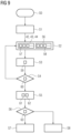
- FIG. 9 shows a flow chart of an exemplary embodiment of the method for detecting an electrical fault in the stator of an electric machine
- FIG. 10 shows a schematic diagram of a further exemplary embodiment of an electric machine arrangement
- FIG. 11 shows a schematic diagram of a further exemplary embodiment of an electric machine arrangement.
- FIG. 1 shows a wind turbine 1 comprising an electric machine arrangement that in turn comprises the electric machine 2 , in the example a generator, and a monitoring device used to detect electrical faults in a stator 4 of the electric machine 2 .
- the rotor 3 of the electric machine 2 is connected to the hub 5 of the wind turbine that carries the blades 6 .
- the stator 4 is attached to a nacelle 7 that is carried by a tower 8 .
- the rotor 3 is arranged outside of the stator 4 in the electric machine 2 , it would however also be possible to use a stator surrounding the rotor.
- FIG. 1 For reasons of simplicity and clarity only a few of the components of the monitoring device are shown in FIG. 1 , namely the current sensors 9 - 11 and a processing unit 12 .
- FIG. 2 A more detailed schematic diagram of the monitoring device 14 and its interaction with the electric machine 2 , namely with the different windings 19 - 27 of the stator 4 of the electric machine 2 , is shown in FIG. 2 .
- FIG. 2 only shows the use of the monitoring device 14 to monitor a single segment 16 of the stator 4 .
- additional current sensors could be used to monitor currents through the further windings 22 - 27 and therefore to also detect electrical faults in the further segments 17 , 18 .
- the use of n ⁇ 1 sensors per phase is sufficient, wherein n is the number of stator segments.
- the electric machine 2 comprises three groups 38 , 51 , 52 of windings 19 - 27 , wherein the windings 19 - 27 of each group 38 , 51 , 52 are assigned to a respective phase 28 - 30 of the electric machine 2 .
- the windings 19 , 22 and 25 are part of the group 38
- the windings 20 , 23 and 26 are part of the group 51
- the windings 21 , 24 and 27 are part of the group 52 .
- One side of the windings 19 - 27 of the respective group 38 , 51 , 52 is connected to a respective phase connection 31 - 33 of the respective group 38 , 51 , 52 .
- the phase connections 31 , 32 , 33 can be connected to a circuit breaker 34 of the electric machine 2 or further electronics of the electric machine 2 .
- the stator 4 comprises several segments 16 , 17 , 18 , each of the segments 16 , 17 , 18 comprising a single winding 19 - 27 from each of the groups 38 , 51 , 52 , wherein the three windings 19 - 27 of the respective segment 16 , 17 , 18 are connected to a respective neutral point 35 , 36 , 37 of the three phase system.
- typically stators 4 with more than three segments 16 , 17 , 18 e.g., stators using twelve segments, are used.
- the electrical fault of the winding 19 will result in the winding 19 having a different impedance than the further windings 22 , 25 of the group 38 . If the neutral points 35 , 36 , 37 of the different segments 16 , 17 , 18 would be directly connected, this would lead a circular current within the phase 28 when the rotor 3 is rotating.
- the currents 42 - 44 measured by the current sensors 9 - 11 are illustrated in FIGS. 3 to 5 for different rotational speeds of the rotor 3 .
- the respective x-axis 40 corresponds to the time and the respective y-axis 41 responds to the measured current.
- the data shown in FIG. 3 was acquired at a very low rotational speed of 1 rpm
- the data shown in FIG. 4 was acquired at a higher rotational speed of 4 rpm
- the data shown in FIG. 5 was acquired at a rotational speed slightly below the cut-in speed of the wind turbine, at which the electric machine 2 would be connected to a load 55 , in the example at a speed of 10.3 rpm.
- a further effect of an electrical fault in the winding 19 is a ripple of the torque acting on the rotor 3 .
- This effect is shown in FIGS. 6 to 8 , wherein the respective x-axis 45 shows the time and the respective y-axis shows the calculated torque, in the example in the unit of 10 4 Nm.
- the measurements 49 in FIG. 6 were recorded at 1 rpm, the measurements 48 in FIG. 7 were recorded at 4 rpm and the measurements 47 in FIG. 8 were recorded at 10.3 rpm.
- the method comprises the determination of a current between a respective subgroup 64 , 65 , 66 of the respective group 38 , 51 , 52 of windings 19 - 27 and a distinct further subgroup 39 , 53 , 54 of the windings 19 - 27 of the same group 38 , 51 , 52 in step S 2 and the evaluation of a fault condition 63 in step S 6 that depends on these currents. If fault condition 63 is fulfilled, a signal 83 is output to personal and/or a device 15 .
- step S 0 In an initial state in step S 0 , the wind turbine 1 is at a standstill.
- actuators 50 are used to pitch the rotor blades 6 . Therefore, the hub 5 and the rotor 3 start to rotate with an increasing rotational speed.
- step S 2 While the rotational speed is slowly increasing, a respective measurement 57 is acquired in step S 2 for each of the currents 42 , 43 , 44 via the respective current sensors 9 , 10 , 11 by the processing unit 12 .
- a measure 58 for the vibration 56 is acquired by the processing unit 12 via the accelerometer 13 . It is especially possible to measure vibrations with an accelerometer attached to a stationary part, e.g., a bearing or a stator.
- step S 2 will be repeated multiple times during a time interval during which the rotational speed increases from a standstill to slightly below a cut-in speed at which the electric machine would be connected to a load 55 . Therefore, a respective time sequence of measurements 57 for each of the currents 42 , 43 , 44 and of measures 58 for the vibration 56 is acquired.
- each of the measured currents 42 , 43 , 44 is a current between a subgroup 64 , 65 , 66 of the windings 19 - 27 of a respective group 38 , 51 , 52 of windings 19 - 27 and a further subgroup 39 , 53 , 54 comprising at least one further winding 19 - 27 of the respective group 38 , 51 , 52 of windings 19 - 27 .
- the subgroup 64 only comprises a single winding 19
- the subgroup 65 only comprise a single winding 20
- the subgroup 66 only comprises a single winding 21 .
- the further subgroup 39 comprises the windings 22 and 25
- the further subgroup 53 comprises the windings 23 and 26
- the further subgroup 54 comprises the further windings 24 and 27 .
- step S 3 a rotational speed 59 is determined, e.g., by an additional sensor that is not shown.
- the rotational speed 59 is compared to a threshold 60 in step S 4 and step S 2 is repeated if the rotational speed 59 is below this threshold 60 .
- a respective maximum value 61 is determined for each of the currents 42 , 43 , 44 based on the maximum of the measurements 57 . Additionally, a maximum value 62 is determined for the vibration 56 .
- step S 6 the fault condition 63 is evaluated.
- the fault condition 63 can be fulfilled, when at least one of the maximum values 61 for the currents 42 , 43 , 44 exceeds a given threshold.
- the fault condition can, only be fulfilled when the maximum value 62 for the vibration 56 also exceeds the threshold or when a combined fault value calculated from the maximum values 61 , 62 , e.g., by multiplying the maximum values, exceeds a threshold.
- step S 8 normal operation of the wind turbine 1 can continue in the step S 8 , e.g., by closing the circuit breaker 34 and therefore providing power to the load 55 once a cut-in speed is exceeded.
- the processing unit 12 can output a control signal to an output device 86 .
- the output device 86 can be a device for outputting an optical or an acoustic signal to personal, e.g., a signal lamp, a loudspeaker, etc. It can however be advantageous to instead output a signal 83 to a device 15 , e.g., to a central unit of a wind park, a communication device of service personal, in internal control unit of the wind turbine or the generator itself, etc.
- FIG. 10 shows a different example of an electric machine arrangement that could be used instead of the electric machine arrangement shown in FIG. 2 .
- the electric machine arrangement shown in FIG. 10 comprises an electric machine 82 , wherein only the windings 19 - 27 , 69 - 77 of the stator of this electric machine 82 are shown in FIG. 10 , and a monitoring device 14 that uses six current sensors 9 , 10 , 78 - 81 .
- the windings 19 - 27 , 69 - 77 are separated into groups that are assigned for the phases 28 , 29 , 30 and into segments 16 , 17 , 18 , 67 , 68 , 87 , wherein each segment 16 , 17 , 18 , 67 , 68 , 87 comprises a winding 19 - 27 , 69 - 77 of each of the groups and therefore of each of the phases 28 , 29 , 30 .
- a major difference to the embodiment according to FIG. 2 is the use of a single current measurement and therefore a single current sensor 9 , 10 , 78 , 79 , 80 , 81 to measure a current between two subgroups, each comprising multiple windings 19 - 69 , 70 - 77 .
- the current sensor 9 for example measures a current between a first subgroup comprising the windings 19 and 22 to a further subgroup comprising the windings 25 , 69 , 72 and 75 .
- the current sensor 10 measures the current between a first subgroup comprising the windings 20 , 23 to a further subgroup comprising the windings 26 , 70 , 73 and 76 . Measuring a high current via the current sensor 9 indicates that there is an electrical fault in the windings 19 or 22 . Similarly a high current measured by the current sensor 10 indicates an electrical fault in either the winding 20 or the winding 23 .
- the current sensors 78 , 79 can be used to determine an electrical fault in the segments 18 , 87 and the current sensors 80 , 81 can be used to determine an electrical fault in the segments 67 , 68 .
- FIG. 10 allows for a monitoring of a large number of windings 19 - 27 , 69 - 77 for electrical faults with a pretty good localization of electrical faults within two respective windings.
- the technical complexity of the monitoring device 14 is relatively low, since only six current sensors 9 , 10 , 78 - 81 are necessary for the three segments shown. The number of necessary sensors would obviously increase with the number of used segments.
- FIG. 11 shows another embodiment of an electric machine arrangement. This embodiment is in many aspects similar to the embodiment shown in FIG. 2 , therefore only the distinguishing features will be discussed in detail. For simplicity's sake only the wiring of the windings 20 - 27 and the positions of the current sensors are shown.
- the embodiment uses a common neutral point 88 , wherein the neutral points 35 - 37 of the different segments are connected to the common neutral point 88 via a respective current sensor.
- An electrical fault in a winding 19 - 27 within a segment 16 - 18 changes the potential at the neutral point 35 - 37 of that segment 16 - 18 and therefore causes a current to flow through the respective current sensor 9 - 11 .
- By measuring the currents between the neutral points 35 - 37 and the common neutral point 88 it is therefore possible to localize defects in any of the segments 16 - 18 by using only a single current sensor 9 - 11 per segment.
Landscapes
- Engineering & Computer Science (AREA)
- Power Engineering (AREA)
- Physics & Mathematics (AREA)
- Sustainable Development (AREA)
- Sustainable Energy (AREA)
- Chemical & Material Sciences (AREA)
- Combustion & Propulsion (AREA)
- Mechanical Engineering (AREA)
- General Engineering & Computer Science (AREA)
- Life Sciences & Earth Sciences (AREA)
- General Physics & Mathematics (AREA)
- Fluid Mechanics (AREA)
- Tests Of Circuit Breakers, Generators, And Electric Motors (AREA)
Applications Claiming Priority (3)
| Application Number | Priority Date | Filing Date | Title |
|---|---|---|---|
| EP21172507.2 | 2021-05-06 | ||
| EP21172507.2A EP4087119B1 (de) | 2021-05-06 | 2021-05-06 | Verfahren zur detektion eines elektrischen defekts im stator einer elektrischen maschine, insbesondere im generator einer windturbine |
| EP21172507 | 2021-05-06 |
Publications (2)
| Publication Number | Publication Date |
|---|---|
| US20220357397A1 US20220357397A1 (en) | 2022-11-10 |
| US12078680B2 true US12078680B2 (en) | 2024-09-03 |
Family
ID=75825683
Family Applications (1)
| Application Number | Title | Priority Date | Filing Date |
|---|---|---|---|
| US17/730,546 Active 2042-12-02 US12078680B2 (en) | 2021-05-06 | 2022-04-27 | Method for detecting an electrical fault in the stator of an electric machine, especially in the generator of a wind turbine |
Country Status (3)
| Country | Link |
|---|---|
| US (1) | US12078680B2 (de) |
| EP (1) | EP4087119B1 (de) |
| CN (1) | CN115308636A (de) |
Families Citing this family (3)
| Publication number | Priority date | Publication date | Assignee | Title |
|---|---|---|---|---|
| IT202300018039A1 (it) * | 2023-09-01 | 2025-03-01 | Leitner Spa | Sistema elettrico per impianto di trasporto a fune o per impianto di generazione di energia elettrica |
| CN117235905B (zh) * | 2023-11-14 | 2024-03-19 | 小米汽车科技有限公司 | 电机定子的优化方法、装置、设备及存储介质 |
| CN118013304B (zh) * | 2024-02-19 | 2024-09-13 | 国网湖北省电力有限公司襄阳供电公司 | 一种基于聚类算法的变压器故障定位方法及系统 |
Citations (6)
| Publication number | Priority date | Publication date | Assignee | Title |
|---|---|---|---|---|
| US20110187304A1 (en) * | 2010-02-02 | 2011-08-04 | Gm Global Technology Operations, Inc. | Motor phase winding fault detection method and apparatus |
| US20140306583A1 (en) * | 2011-11-16 | 2014-10-16 | Vestas Wind Systems A/S | Protection of a permanent magnet generator |
| US20150276823A1 (en) * | 2012-11-01 | 2015-10-01 | Abb Research Ltd | Method For Detecting A Fault Condition In An Electrical Machine |
| CN105866614A (zh) | 2016-06-06 | 2016-08-17 | 哈尔滨电机厂有限责任公司 | 汽轮发电机三相突然短路检测装置 |
| US20190238077A1 (en) * | 2018-02-01 | 2019-08-01 | Siemens Gamesa Renewable Energy A/S | Controlling a multi winding set permanent magnet electrical machine |
| US10830208B2 (en) * | 2017-10-13 | 2020-11-10 | General Electric Company | System and method for mitigating blade run-away loads in the event of a pitch system failure |
Family Cites Families (5)
| Publication number | Priority date | Publication date | Assignee | Title |
|---|---|---|---|---|
| JP4418320B2 (ja) * | 2004-07-28 | 2010-02-17 | 株式会社日立産機システム | モータ巻線ターン間部分放電計測方法 |
| CN103293437B (zh) * | 2012-02-27 | 2016-04-20 | 南京南瑞继保电气有限公司 | 同步发电机转子匝间故障时定子绕组电流特征的提取方法 |
| CN105548799B (zh) * | 2015-12-06 | 2019-01-11 | 国家电网公司 | 发电电动机转子绕组匝间短路故障的在线监测方法 |
| EP3588745B1 (de) * | 2018-06-21 | 2020-11-04 | Siemens Gamesa Renewable Energy A/S | Segmentierte statoranordnung mit flexiblen elektrischen verbindungen, generator und windkraftanlage mit solch einer statoranordnung |
| JP2020085773A (ja) * | 2018-11-29 | 2020-06-04 | 株式会社Soken | 絶縁検査方法 |
-
2021
- 2021-05-06 EP EP21172507.2A patent/EP4087119B1/de active Active
-
2022
- 2022-04-27 US US17/730,546 patent/US12078680B2/en active Active
- 2022-05-06 CN CN202210486570.0A patent/CN115308636A/zh active Pending
Patent Citations (7)
| Publication number | Priority date | Publication date | Assignee | Title |
|---|---|---|---|---|
| US20110187304A1 (en) * | 2010-02-02 | 2011-08-04 | Gm Global Technology Operations, Inc. | Motor phase winding fault detection method and apparatus |
| US20140306583A1 (en) * | 2011-11-16 | 2014-10-16 | Vestas Wind Systems A/S | Protection of a permanent magnet generator |
| US20150276823A1 (en) * | 2012-11-01 | 2015-10-01 | Abb Research Ltd | Method For Detecting A Fault Condition In An Electrical Machine |
| CN105866614A (zh) | 2016-06-06 | 2016-08-17 | 哈尔滨电机厂有限责任公司 | 汽轮发电机三相突然短路检测装置 |
| CN105866614B (zh) | 2016-06-06 | 2018-06-01 | 哈尔滨电机厂有限责任公司 | 汽轮发电机三相突然短路检测装置 |
| US10830208B2 (en) * | 2017-10-13 | 2020-11-10 | General Electric Company | System and method for mitigating blade run-away loads in the event of a pitch system failure |
| US20190238077A1 (en) * | 2018-02-01 | 2019-08-01 | Siemens Gamesa Renewable Energy A/S | Controlling a multi winding set permanent magnet electrical machine |
Non-Patent Citations (3)
| Title |
|---|
| European Search Report issued on Oct. 1, 2021 for application No. 21172507.2. |
| F. Cheng, Y. Peng, L. Qu and W. Qiao, "Current-Based Fault Detection and Identification for Wind Turbine Drivetrain Gearboxes," in IEEE Transactions on Industry Applications (Year: 2017). * |
| H. Li, L. Qu, W. Qiao and C. Wei, "Current and rotor position sensor fault detection and isolation for permanent magnet synchronous generators in wind applications," 2017 IEEE Applied Power Electronics Conference and Exposition (APEC) (Year: 2017). * |
Also Published As
| Publication number | Publication date |
|---|---|
| EP4087119B1 (de) | 2025-07-23 |
| EP4087119A1 (de) | 2022-11-09 |
| US20220357397A1 (en) | 2022-11-10 |
| CN115308636A (zh) | 2022-11-08 |
| EP4087119C0 (de) | 2025-07-23 |
Similar Documents
| Publication | Publication Date | Title |
|---|---|---|
| US12078680B2 (en) | Method for detecting an electrical fault in the stator of an electric machine, especially in the generator of a wind turbine | |
| Nandi et al. | Fault diagnosis of electrical machines-a review | |
| US20130278282A1 (en) | Monitoring and fault diagnosis of an electric machine | |
| CN113228442B (zh) | 用于确定发电机布置中的短路故障的位置的方法、发电机布置、风力涡轮机、计算机程序和电可读介质 | |
| US10473708B2 (en) | Methods and systems for real-time monitoring of the insulation state of wind-powered generator windings | |
| CN109425488B (zh) | 确定轴承状态的方法、用于确定轴承状态的模块、轨道车辆和系统 | |
| JP2015215275A (ja) | 劣化診断システム | |
| WO2014067742A1 (en) | A method for detecting a fault condition in an electrical machine | |
| EP3480610A1 (de) | Diagnose eines wicklungssatzes eines stators | |
| WO2020144965A1 (ja) | 電力変換装置、回転機システム、及び診断方法 | |
| Park et al. | Flux-based detection of non-adjacent rotor bar damage in squirrel cage induction motors | |
| KR102028710B1 (ko) | 3상 교류 돌극형 동기기의 댐퍼 바 고장 진단 시스템, 방법, 및 상기 방법을 실행시키기 위한 컴퓨터 판독 가능한 프로그램을 기록한 기록 매체 | |
| Sabir et al. | Detection and localization of electrical faults in a three phase synchronous generator with rectifier | |
| US11509255B2 (en) | Electric machine fault detection scheme | |
| Kumar et al. | LabVIEW based condition monitoring of induction machines | |
| Royo et al. | Machine current signature analysis as a way for fault detection in permanent magnet motors in elevators | |
| Oviedo et al. | Motor current signature analysis and negative sequence current based stator winding short fault detection in an induction motor | |
| Bellini et al. | Diagnosis of mechanical faults by spectral kurtosis energy | |
| KR102212084B1 (ko) | 동기전동기의 고장 진단 방법 | |
| KR20200089465A (ko) | 3상 권선형 동기 전동기의 계자권선 단락 검출장치 및 그 방법 | |
| Sabir et al. | Open and Short Circuit Fault detection in Alternators using the rectified DC output voltage | |
| Kumar et al. | Rotor mounted wireless sensors for condition monitoring of brushless synchronous generator | |
| EP4404456A1 (de) | Elektromechanisches system mit mindestens einer elektrischen maschine und verfahren zur erkennung eines statorwicklungsfehlers | |
| Salah et al. | Load torque effect on diagnosis techniques consistency for detection of mechanical unbalance | |
| Kim et al. | Rotor fault detection system for inverter driven induction motor using currents signal |
Legal Events
| Date | Code | Title | Description |
|---|---|---|---|
| FEPP | Fee payment procedure |
Free format text: ENTITY STATUS SET TO UNDISCOUNTED (ORIGINAL EVENT CODE: BIG.); ENTITY STATUS OF PATENT OWNER: LARGE ENTITY |
|
| STPP | Information on status: patent application and granting procedure in general |
Free format text: DOCKETED NEW CASE - READY FOR EXAMINATION |
|
| AS | Assignment |
Owner name: SIEMENS GAMESA RENEWABLE ENERGY A/S, DENMARK Free format text: ASSIGNMENT OF ASSIGNORS INTEREST;ASSIGNOR:SIEMENS GAMESA RENEWABLE ENERGY LIMITED;REEL/FRAME:061731/0876 Effective date: 20220608 Owner name: SIEMENS GAMESA RENEWABLE ENERGY A/S, DENMARK Free format text: ASSIGNMENT OF ASSIGNORS INTEREST;ASSIGNORS:FREIRE, NUNO MIGUEL AMARAL;R PILLAI, RAHUL;SZCZESNY, IRENEUSZ GRZEGORZ;SIGNING DATES FROM 20220524 TO 20220527;REEL/FRAME:061731/0842 Owner name: SIEMENS GAMESA RENEWABLE ENERGY LIMITED, UNITED KINGDOM Free format text: ASSIGNMENT OF ASSIGNORS INTEREST;ASSIGNOR:BHIDE, RAVINDRA;REEL/FRAME:061731/0732 Effective date: 20220601 |
|
| STPP | Information on status: patent application and granting procedure in general |
Free format text: NON FINAL ACTION MAILED |
|
| STPP | Information on status: patent application and granting procedure in general |
Free format text: RESPONSE TO NON-FINAL OFFICE ACTION ENTERED AND FORWARDED TO EXAMINER |
|
| STPP | Information on status: patent application and granting procedure in general |
Free format text: NOTICE OF ALLOWANCE MAILED -- APPLICATION RECEIVED IN OFFICE OF PUBLICATIONS |
|
| STCF | Information on status: patent grant |
Free format text: PATENTED CASE |