US12068705B2 - Apparatus and method for inverter control - Google Patents
Apparatus and method for inverter control Download PDFInfo
- Publication number
- US12068705B2 US12068705B2 US17/440,515 US201917440515A US12068705B2 US 12068705 B2 US12068705 B2 US 12068705B2 US 201917440515 A US201917440515 A US 201917440515A US 12068705 B2 US12068705 B2 US 12068705B2
- Authority
- US
- United States
- Prior art keywords
- denotes
- motor
- equation
- transfer function
- voltage
- Prior art date
- Legal status (The legal status is an assumption and is not a legal conclusion. Google has not performed a legal analysis and makes no representation as to the accuracy of the status listed.)
- Active, expires
Links
- 238000000034 method Methods 0.000 title claims abstract description 42
- 230000001360 synchronised effect Effects 0.000 claims abstract description 29
- 238000012546 transfer Methods 0.000 claims description 51
- 238000005070 sampling Methods 0.000 claims description 32
- 230000004044 response Effects 0.000 claims description 9
- 238000009499 grossing Methods 0.000 claims description 5
- 238000010586 diagram Methods 0.000 description 24
- 230000009466 transformation Effects 0.000 description 14
- 230000000694 effects Effects 0.000 description 12
- 230000014509 gene expression Effects 0.000 description 9
- 238000012545 processing Methods 0.000 description 7
- 238000005094 computer simulation Methods 0.000 description 5
- 230000008569 process Effects 0.000 description 4
- 230000004907 flux Effects 0.000 description 2
- 238000012986 modification Methods 0.000 description 2
- 230000004048 modification Effects 0.000 description 2
- 230000008901 benefit Effects 0.000 description 1
- 239000002131 composite material Substances 0.000 description 1
- 230000003247 decreasing effect Effects 0.000 description 1
- 230000001934 delay Effects 0.000 description 1
- 238000009795 derivation Methods 0.000 description 1
- 238000011161 development Methods 0.000 description 1
- 230000004069 differentiation Effects 0.000 description 1
- 239000013643 reference control Substances 0.000 description 1
Images


Classifications
-
- H—ELECTRICITY
- H02—GENERATION; CONVERSION OR DISTRIBUTION OF ELECTRIC POWER
- H02M—APPARATUS FOR CONVERSION BETWEEN AC AND AC, BETWEEN AC AND DC, OR BETWEEN DC AND DC, AND FOR USE WITH MAINS OR SIMILAR POWER SUPPLY SYSTEMS; CONVERSION OF DC OR AC INPUT POWER INTO SURGE OUTPUT POWER; CONTROL OR REGULATION THEREOF
- H02M7/00—Conversion of AC power input into DC power output; Conversion of DC power input into AC power output
- H02M7/42—Conversion of DC power input into AC power output without possibility of reversal
- H02M7/44—Conversion of DC power input into AC power output without possibility of reversal by static converters
- H02M7/48—Conversion of DC power input into AC power output without possibility of reversal by static converters using discharge tubes with control electrode or semiconductor devices with control electrode
- H02M7/53—Conversion of DC power input into AC power output without possibility of reversal by static converters using discharge tubes with control electrode or semiconductor devices with control electrode using devices of a triode or transistor type requiring continuous application of a control signal
- H02M7/537—Conversion of DC power input into AC power output without possibility of reversal by static converters using discharge tubes with control electrode or semiconductor devices with control electrode using devices of a triode or transistor type requiring continuous application of a control signal using semiconductor devices only, e.g. single switched pulse inverters
- H02M7/5387—Conversion of DC power input into AC power output without possibility of reversal by static converters using discharge tubes with control electrode or semiconductor devices with control electrode using devices of a triode or transistor type requiring continuous application of a control signal using semiconductor devices only, e.g. single switched pulse inverters in a bridge configuration
- H02M7/53871—Conversion of DC power input into AC power output without possibility of reversal by static converters using discharge tubes with control electrode or semiconductor devices with control electrode using devices of a triode or transistor type requiring continuous application of a control signal using semiconductor devices only, e.g. single switched pulse inverters in a bridge configuration with automatic control of output voltage or current
- H02M7/53873—Conversion of DC power input into AC power output without possibility of reversal by static converters using discharge tubes with control electrode or semiconductor devices with control electrode using devices of a triode or transistor type requiring continuous application of a control signal using semiconductor devices only, e.g. single switched pulse inverters in a bridge configuration with automatic control of output voltage or current with digital control
-
- H—ELECTRICITY
- H02—GENERATION; CONVERSION OR DISTRIBUTION OF ELECTRIC POWER
- H02P—CONTROL OR REGULATION OF ELECTRIC MOTORS, ELECTRIC GENERATORS OR DYNAMO-ELECTRIC CONVERTERS; CONTROLLING TRANSFORMERS, REACTORS OR CHOKE COILS
- H02P27/00—Arrangements or methods for the control of AC motors characterised by the kind of supply voltage
- H02P27/04—Arrangements or methods for the control of AC motors characterised by the kind of supply voltage using variable-frequency supply voltage, e.g. inverter or converter supply voltage
- H02P27/06—Arrangements or methods for the control of AC motors characterised by the kind of supply voltage using variable-frequency supply voltage, e.g. inverter or converter supply voltage using DC to AC converters or inverters
- H02P27/08—Arrangements or methods for the control of AC motors characterised by the kind of supply voltage using variable-frequency supply voltage, e.g. inverter or converter supply voltage using DC to AC converters or inverters with pulse width modulation
-
- H—ELECTRICITY
- H02—GENERATION; CONVERSION OR DISTRIBUTION OF ELECTRIC POWER
- H02M—APPARATUS FOR CONVERSION BETWEEN AC AND AC, BETWEEN AC AND DC, OR BETWEEN DC AND DC, AND FOR USE WITH MAINS OR SIMILAR POWER SUPPLY SYSTEMS; CONVERSION OF DC OR AC INPUT POWER INTO SURGE OUTPUT POWER; CONTROL OR REGULATION THEREOF
- H02M7/00—Conversion of AC power input into DC power output; Conversion of DC power input into AC power output
- H02M7/42—Conversion of DC power input into AC power output without possibility of reversal
- H02M7/44—Conversion of DC power input into AC power output without possibility of reversal by static converters
- H02M7/48—Conversion of DC power input into AC power output without possibility of reversal by static converters using discharge tubes with control electrode or semiconductor devices with control electrode
- H02M7/53—Conversion of DC power input into AC power output without possibility of reversal by static converters using discharge tubes with control electrode or semiconductor devices with control electrode using devices of a triode or transistor type requiring continuous application of a control signal
- H02M7/537—Conversion of DC power input into AC power output without possibility of reversal by static converters using discharge tubes with control electrode or semiconductor devices with control electrode using devices of a triode or transistor type requiring continuous application of a control signal using semiconductor devices only, e.g. single switched pulse inverters
- H02M7/539—Conversion of DC power input into AC power output without possibility of reversal by static converters using discharge tubes with control electrode or semiconductor devices with control electrode using devices of a triode or transistor type requiring continuous application of a control signal using semiconductor devices only, e.g. single switched pulse inverters with automatic control of output wave form or frequency
- H02M7/5395—Conversion of DC power input into AC power output without possibility of reversal by static converters using discharge tubes with control electrode or semiconductor devices with control electrode using devices of a triode or transistor type requiring continuous application of a control signal using semiconductor devices only, e.g. single switched pulse inverters with automatic control of output wave form or frequency by pulse-width modulation
-
- H—ELECTRICITY
- H02—GENERATION; CONVERSION OR DISTRIBUTION OF ELECTRIC POWER
- H02P—CONTROL OR REGULATION OF ELECTRIC MOTORS, ELECTRIC GENERATORS OR DYNAMO-ELECTRIC CONVERTERS; CONTROLLING TRANSFORMERS, REACTORS OR CHOKE COILS
- H02P23/00—Arrangements or methods for the control of AC motors characterised by a control method other than vector control
- H02P23/14—Estimation or adaptation of motor parameters, e.g. rotor time constant, flux, speed, current or voltage
-
- H—ELECTRICITY
- H02—GENERATION; CONVERSION OR DISTRIBUTION OF ELECTRIC POWER
- H02P—CONTROL OR REGULATION OF ELECTRIC MOTORS, ELECTRIC GENERATORS OR DYNAMO-ELECTRIC CONVERTERS; CONTROLLING TRANSFORMERS, REACTORS OR CHOKE COILS
- H02P25/00—Arrangements or methods for the control of AC motors characterised by the kind of AC motor or by structural details
- H02P25/02—Arrangements or methods for the control of AC motors characterised by the kind of AC motor or by structural details characterised by the kind of motor
- H02P25/022—Synchronous motors
- H02P25/024—Synchronous motors controlled by supply frequency
- H02P25/026—Synchronous motors controlled by supply frequency thereby detecting the rotor position
-
- H—ELECTRICITY
- H02—GENERATION; CONVERSION OR DISTRIBUTION OF ELECTRIC POWER
- H02M—APPARATUS FOR CONVERSION BETWEEN AC AND AC, BETWEEN AC AND DC, OR BETWEEN DC AND DC, AND FOR USE WITH MAINS OR SIMILAR POWER SUPPLY SYSTEMS; CONVERSION OF DC OR AC INPUT POWER INTO SURGE OUTPUT POWER; CONTROL OR REGULATION THEREOF
- H02M1/00—Details of apparatus for conversion
- H02M1/12—Arrangements for reducing harmonics from AC input or output
Definitions
- the present disclosure relates to an inverter control apparatus and an inverter control method.
- alternating-current (AC) motor systems digital inverters are becoming common due to the development of microprocessors and various sensors.
- magnetic flux reference control referred to as vector control
- performance of vector control can be determined by current control performance of the digital inverter.
- a sampling frequency is limited due to problems including an arithmetic operation time of a controller and heat of a power device. Therefore, when the sampling frequency of the digital inverter is not sufficiently greater than a rotation frequency of the motor, current control performance tends to be degraded or unstable. This problem is prominent in large-capacity systems or high-speed operation systems using permanent magnet motors.
- the present disclosure is directed to providing an inverter control apparatus and an inverter control method which improve modeling accuracy of a motor control system and secure command convergence performance and stability of an inverter.
- One aspect of the present disclosure provides an inverter control method including determining a first voltage equation for a motor on a stationary coordinate system in a continuous time domain, reflecting a zero-order hold (ZOH) and a time delay to the first voltage equation and determining a second voltage equation, discretizing the second voltage equation and determining a third voltage equation, reflecting a rotor position and a speed of the motor and determining a fourth voltage equation on a synchronous coordinate system in a discrete time domain, determining a transfer function of a current control closed-loop on the synchronous coordinate system in the discrete time domain from a transfer function of a current control response characteristic in the discrete time domain, and determining a transfer function of current control to be provided to an inverter using the transfer function of the current control closed-loop and the fourth voltage equation.
- ZOH zero-order hold
- the first voltage equation may be determined by the following equation:
- G p (s) may denote the voltage equation on the stationary coordinate system
- V dqs s may denote an input voltage on the stationary coordinate system
- i dqs s may denote an output current on the stationary coordinate system
- R s may denote rotor resistance of the motor
- L s may denote rotor inductance of the motor.
- the second voltage equation may be determined by the following equation:
- G ZOH (s) may denote a transfer function to which the ZOH is reflected
- G d (s) may denote a transfer function to which the time delay is reflected
- T samp may denote a sampling period
- the third voltage equation may be determined by the following equation:
- ⁇ e may denote a rotor speed of the motor.
- the fourth voltage equation may be determined by the following equation:
- the current control response characteristic in the discrete time domain may be designed using a low-pass filter, and the current control response characteristic may be determined by the following equation:
- K may denote a dynamic characteristic of an actual current with respect to a current command.
- the transfer function of the current control may be determined by the following equation:
- An inverter control method of determining a transfer function of current control which is a control signal in a discrete time domain, so as to turn a plurality of switching devices, each outputting an alternating-current (AC) voltage of an inverter, on and off
- the inverter control method comprising: discretizing a voltage equation for a motor on a stationary coordinate system, in which a zero-order hold (ZOH) and a delay are reflected, in a continuous time domain, and reflecting a rotor position and a speed of the motor and determining a voltage equation of the motor on a synchronous coordinate system in a discrete time domain.
- ZOH zero-order hold
- coordinate transformation is performed in a discrete time domain during system modeling so that there is an effect in that a sampling effect can be reflected in the system modeling and a current command convergence and stability can be improved.
- FIG. 1 is a block diagram illustrating a general inverter control system for describing signal processing of a digital inverter.
- FIG. 2 is a graph showing an example of a continuous time output signal that is sampled in units of 0.1 seconds with respect to a continuous time input signal by that of FIG. 1 .
- FIG. 3 is a block diagram of a system in which that of FIG. 1 is simplified in a continuous time domain.
- FIG. 4 is an exemplary diagram for describing a current control loop of a digital inverter.
- FIG. 5 is a conceptual diagram illustrating a digital inverter to which a conventional zero-order hold (ZOH) and a time delay are reflected.
- ZOH zero-order hold
- FIG. 6 is an exemplary diagram for describing a control closed loop circuit of a digital inverter including a motor.
- FIG. 7 is an exemplary diagram illustrating that of FIG. 6 simplified in terms of a control algorithm of a controller.
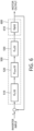
- FIG. 8 is a flowchart for describing an inverter control method according to a related art.
- FIG. 9 is a block diagram illustrating an inverter system to which an inverter control apparatus is applied according to one embodiment of the present disclosure.
- FIG. 10 is a schematic exemplary diagram illustrating a controller and a motor of FIG. 9 , which are modeled in a discrete time domain.
- FIG. 11 is a detailed block diagram illustrating the inverter control apparatus according to one embodiment of the present disclosure.
- FIG. 12 is a flowchart for describing an inverter control method according to one embodiment of the present disclosure.
- FIG. 13 shows exemplary diagrams illustrating a relationship between a command current and an output current according to a conventional control method.
- FIG. 14 shows exemplary diagrams illustrating a relationship between a command current and an output current according to a control method of one embodiment of the present disclosure.
- first can be used to describe various components, but the components should not be limited by these terms. These terms may be used only for the purpose of distinguishing one component from another component. For example, without departing from the scope of the present disclosure, a first component may be referred to as a second component, and similarly, the second component may also be referred to as the first component.
- first component may be referred to as a second component, and similarly, the second component may also be referred to as the first component.
- singular form includes the plural form unless the context clearly notes otherwise. Unless otherwise defined, the terms used in the embodiments of the present disclosure may be construed as commonly known to those skilled in the art.
- FIG. 1 is a block diagram illustrating a general inverter control system for describing signal processing of a digital inverter.
- a discrete time converter 110 converts continuous time input signals, such as a voltage, a current, and a rotation speed which are generated by a motor, into discrete time signals by a sample-and-hold method.
- the sample-and-hold method is a method of memorizing a certain signal and holding the certain signal until the next signal to be memorized is input and is a common method of converting a continuous time signal into a discrete time signal.
- An analog-to-digital converter (ADC) 120 quantizes the discrete time signal to allow the discrete time signal to be arithmetically processed.
- the above-described quantized signal is output as another quantized signal through various arithmetic operation processes of the controller 130 and is finally converted into a continuous time output signal through a digital-to-analog converter (DAC) 140 to be output.
- DAC digital-to-analog converter
- FIG. 2 is a graph showing an example of a continuous time output signal that is sampled in units of 0.1 seconds with respect to a continuous time input signal by that of FIG. 1 .
- the signal processing process refers to a composite system in which a continuous time domain and a discrete time domain are mixed.
- a unit of discrete time that is, a sampling period of the system
- an operation for a discrete time domain may be regarded as a continuous time domain, and thus as shown in FIG. 3 , the signal processing process of FIG. 1 may be simplified in the continuous time domain.
- FIG. 3 is a block diagram of a system in which that of FIG. 1 is simplified in a continuous time domain, and the system may be regarded as an inverter controller 300 in a continuous time domain.
- ZOH zero-order hold
- Equation 1 a transfer function of the ZOH method is expressed as Equation 1 below in a continuous time frequency domain.
- s denotes an operator corresponding to the Laplace transform, is used to convert a time function including a differentiation into a frequency domain, and operates in the continuous time domain.
- FIG. 4 is an exemplary diagram for describing a current control loop of a digital inverter.
- an arithmetic operation necessary for current control is performed in the controller of the inverter during the sampling period T samp
- an arithmetic operation of the controller on a pulse width modulation (PWM) switching indicating an output of the inverter is completed and output during the next period.
- PWM pulse width modulation
- a time delay corresponding to the sampling period occurs. Similar to the ZOH method, an effect of the time delay can be ignored when the sampling period is sufficiently fast, whereas the effect cannot be ignored in the high-speed current control system.
- Equation 2 Equation 2
- the digital inverter has the ZOH and time delay characteristics, and in consideration of these characteristics, a relational expression for input and output signals of the digital inverter of FIG. 1 may be expressed in the continuous time frequency domain.
- FIG. 5 is a conceptual diagram illustrating a digital inverter to which a conventional ZOH and a time delay are reflected.
- Equation 3 the final relational expression for the input and output of the digital inverter may be integrated in the continuous time domain to be expressed as Equation 3, and when a control algorithm G c (s) of a controller 510 is designed in the form of Equation 3, ZOHs and time delays of a ZOH unit 520 and a time delay unit 530 of the digital inverter 500 should be reflected.
- FIG. 6 is an exemplary diagram for describing a control closed loop circuit of a digital inverter including a motor, and it can be seen that, in addition to the ZOH unit 520 and the time delay unit 530 , an item to be considered in designing the control algorithm of the controller 510 is modeling for a motor 600 .
- the performance of the inverter control apparatus depends on accuracy of the modeling even for the same motor.
- FIG. 7 is an exemplary diagram illustrating that of FIG. 6 simplified in terms of a control algorithm of a controller.
- a control closed loop block diagram may be represented to be modified into one block 620 by combining a motor modeling unit 610 of the motor 600 into items obtained by considering the ZOH and the time delay.
- the three-phase alternating-current (AC) motor 600 is modeled in the form of d-axis and q-axis signals through coordinate transformation.
- AC motor 600 There are various types of the AC motor 600 .
- the various types of the AC motor 600 an example of a surface-attached permanent magnet motor will be described.
- An output voltage equation of the motor is expressed as a voltage equation of the motor in a continuous-time stationary coordinate system as in Equation 4 below.
- V ds s V qs s ] R s [ i ds s i qs s ] + d dt ⁇ ( [ L s 0 0 L s ] [ i ds s i qs s ] + ⁇ PM [ cos ⁇ ⁇ r sin ⁇ ⁇ r ] ) [ Equation ⁇ 4 ]
- V ds s denotes a d-axis input voltage on the stationary coordinate system
- V qs s denotes a q-axis input voltage on the stationary coordinate system
- i ds s denotes a d-axis output current on the stationary coordinate system
- i qs s denotes a q-axis output current on the stationary coordinate system.
- R s denotes resistance of a motor stator
- L s denotes inductance of the motor stator
- ⁇ PM denotes magnetic flux interlinkage of a permanent magnet
- ⁇ r denotes a position of the permanent magnet of the motor.
- the voltage equation on the synchronous coordinate system may also be obtained in the form of Equation 6 through coordinate transformation synchronized with the position of the motor expressed as Equation 5.
- V ds e denotes a d-axis input voltage on the synchronous coordinate system
- V qs e denotes a q-axis input voltage on the synchronous coordinate system
- i ds e denotes a d-axis output current on the synchronous coordinate system
- i qs e denotes a q-axis output current on the synchronous coordinate system
- ⁇ e denotes a position of the motor rotor
- ⁇ e denotes a speed of the motor rotor.
- Equations 7 and 8 When the Laplace transform is applied to the voltage equations of Equations 4 and 6 to obtain a relational expression of an output current to a voltage input of the motor, the relational expression may be expressed as transfer functions of Equations 7 and 8.
- G c (s) of the controller 510 is designed through analysis of a closed loop circuit of FIG. 6 .
- G p (s) refers to G p s (s) or G p e (s) in Equations 7 and 8.
- Equations 7 and 8 it is possible to determine a transfer function of the control closed loop modified in one block 610 in which the ZOH and delay effects of FIG. 7 and the motor modeling are combined.
- Equation 11 the voltage equation on the synchronous coordinate system of Equation 8 is used for the motor modeling.
- a relational expression shown in Equation 11 may be derived through the system shown in FIG. 7 .
- i dqs e i dqs e * G closed ⁇ ( s ) [ Equation ⁇ ⁇ 10 ]
- Equation 11 when the relational expression of Equation 11 is utilized through a known G T (s) and G closed (s) directly designed by the user, the control algorithm G e (s) of the controller 510 may be determined in the form of Equation 12.
- Equation 13 a control algorithm G c (z), which is capable of being finally implemented in a discretized form by applying a z transform to G closed (s) and G T (s), is designed as in Equation 13.
- the z transform transforms a signal in the time domain represented as a real number sequence or a complex number sequence in signal processing into an expression in a complex frequency domain
- the z transform may be referred to as a transformation into a discrete time domain corresponding to the Laplace transform for a continuous time signal.
- the description thereof is well known to those skilled in the art to which the present disclosure pertains, and thus a detailed description thereof will be omitted herein.
- the control algorithm G c (z) of the controller 510 as in Equation 16 may be designed through G T (z) of Equation 15.
- G closed ⁇ ( z ) K z 2 - z + K [ Equation ⁇ ⁇ 14 ]
- G T ⁇ ( z ) ⁇ Z ⁇ ⁇ G Z ⁇ O ⁇ H ⁇ ( s ) ⁇ G d ⁇ ( s ) ⁇
- G P ⁇ ( s ) ⁇ ⁇ R s - j ⁇ ⁇ ⁇ e ⁇ L s R s 2 + ⁇ e 2 ⁇ L s 2 ⁇ 1 - e - ( R s / L s + j ⁇ ⁇ ⁇ e ) ⁇ T samp z ⁇ ( z - e - ( R s / L s + j ⁇ ⁇ ⁇ e ) ⁇ T samp ) [ Equation ⁇ ⁇ 15 ]
- G c ⁇ ( z ) K ⁇ ( R s 2 + ⁇ e 2 ⁇ L s 2 ) ⁇ (
- K used in the above equations denotes a controller variable.
- FIG. 8 is a flowchart for describing an inverter control method according to a related art.
- Equation 4 a voltage equation of the motor on a stationary coordinate system is determined in the continuous time domain (S 810 ). This is expressed as Equation 4. Thereafter, coordinate transformation is performed through Equation 5 (S 820 ), and the voltage equation of the motor on the synchronous coordinate system may be determined in the continuous time domain (S 830 ). This is expressed as Equation 6.
- Equation 9 the voltage equation of the motor on the synchronous coordinate system is determined as in Equation 9 in the continuous time domain in which the ZOH and the time delay are combined (S 840 ), and a transfer function of the current control closed-loop on the synchronous coordinate system is determined as in Equation 11 in the continuous time domain (S 850 ).
- the transfer function of the current control closed loop on the synchronous coordinate system is discretized in the continuous time domain to determine the transfer function of the current control closed loop on the synchronous coordinate system in the discrete time domain as in Equation 12 (S 860 ), and by using the voltage equation of the motor on the synchronous coordinate system in the continuous time domain, in which the transfer function of the current control response characteristic in the discrete time domain of Equation 14 and the discretized ZOH and time delay of Equation 15 are combined, a current control transfer function of the inverter is determined as in Equation 16 (S 870 ) and then transmitted to the inverter (S 880 ).
- the voltage equation of Equation 6 on the synchronous coordinate system which corresponds to the last operation of the motor modeling, is derived through the coordinate transformation of Equation 5 to the voltage equation of Equation 4 on the stationary coordinate system.
- the sampling period is used as a variable. That is, a result of the coordinate transformation is varied according to the sampling period.
- the conventional system is not a problem in a general inverter control system in which the sampling period is sufficiently short, whereas in a high-speed current control system, accuracy of modeling for the system is reduced, and thus there is a problem in that convergence of the inverter controller on the command is degraded and a stable operation range is limited.
- the system according to one embodiment of the present disclosure is for improving modeling accuracy by reflecting the sampling effect on the coordinate transformation and for securing command convergence performance and stability of the inverter controller in a condition of a lower sampling index.
- FIG. 9 is a block diagram illustrating an inverter system to which an inverter control apparatus is applied according to one embodiment of the present disclosure.
- the inverter system of one embodiment of the present disclosure may include a controller 3 for transmitting an on/off control signal to an inverter part 13 of an inverter 1 , which drives a motor 2 .
- the inverter 1 may include a rectifier 11 for rectifying a three-phase AC power which is input, a smoothing part 12 for smoothing and storing a direct-current (DC) voltage rectified by the rectifier 11 , and the inverter part 13 for outputting the DC voltage stored in the smoothing part 12 as an AC voltage having a predetermined voltage and a frequency according to a control signal of the controller 3 .
- the AC voltage output from the inverter part 13 is provided to the motor 2 .
- FIG. 10 is a schematic exemplary diagram illustrating the controller 3 and the motor 2 of FIG. 9 , which are modeled in a discrete time domain that is shown to correspond to FIG. 7 according to the related art, and may include a control modeling part 5 and a motor modeling part 6 .
- the motor modeling part 6 may combine the voltage equation on the stationary coordinate system of Equation 7 with the ZOH and delay effects of Equations 1 and 2 to obtain a result for the motor modeling as in Equation 17.
- Equation 17 Z-transform is performed to discretize Equation 17 as follows.
- Equation 19 a voltage equation on the synchronous coordinate system, in which a ZOH and a time delay for a discrete time are combined, may be determined as in Equation 19.
- Equation 20 a transfer function of a current control closed loop on the synchronous coordinate system may be obtained as in Equation 20.
- Equation 20 When Equation 20 is expressed as G prop (z), Equation 21 is obtained, and when the dynamic characteristic of the actual current with respect to the current command is designed using a low-pass filter as in Equation 14, an algorithm of the control modeling part 5 may be derived as in Equation 22.
- G prop ⁇ ( z ) G closed ⁇ ( z ) G T ′ ⁇ ( z ) ⁇ ( 1 - G closed ⁇ ( z ) ) [ Equation ⁇ ⁇ 21 ]
- K denotes the controller variable and denotes the dynamic characteristic of the actual current with respect to the current command.
- Equation 22 When Equation 22 is compared with Equation 16, it can be seen that the sampling effect, which is not considered in the coordinate transformation in Equation 16, is reflected and it can be seen that the control variable K is used as in Equation 16.
- control modeling part 5 of one embodiment of the present disclosure complexity is the same as in the related art, whereas accuracy of the system modeling is increased so that the current control performance can be improved.
- FIG. 11 is a detailed block diagram illustrating the inverter control apparatus according to one embodiment of the present disclosure that shows an exemplary diagram in which Equation 22 is implemented.
- FIG. 12 is a flowchart for describing an inverter control method according to one embodiment of the present disclosure.
- control modeling part 5 may determine a voltage equation of the motor on the stationary coordinate system as in Equation 7 in the continuous time domain (S 10 ).
- control modeling part 5 may determine the voltage equation of the motor in the continuous time stationary coordinate system, in which the ZOH and the time delay are combined, as in Equation 17 (S 11 ), discretize the voltage equation of the motor, and determine a voltage equation of the motor in the discrete time stationary coordinate system, in which the ZOH and the time delay are combined, as in Equation 18 (S 12 ).
- control modeling part 5 may perform coordinate transformation using Equation 5 (S 13 ) and determine a voltage equation of the motor in a discrete time synchronous coordinate system, in which the ZOH and the time delay are combined, as in Equation 19 (S 14 ).
- the control modeling part 5 may determine a transfer function of a current control closed loop in the discrete time synchronous coordinate system as in Equation 20 from the transfer function of the discrete time current control response characteristic of Equation 14 (S 15 ).
- control modeling part 5 may determine a transfer function of the current control as in Equation 22 from the transfer function of the current control closed loop of Equation 20 (S 16 ) and provide the transfer function of the current control to the inverter 1 .
- FIG. 13 shows exemplary diagrams illustrating a relationship between a command current and an output current according to a conventional control method
- FIG. 14 shows exemplary diagrams illustrating a relationship between a command current and an output current according to a control method of one embodiment of the present disclosure, and each drawing shows a condition in which a sampling frequency is 2 kHz and an operating frequency is 500 Hz, that is, a condition in which a sampling index is four.
- IdseRej and IqseRej denote a current command
- Idse and Iqse denote an actual current.
- the coordinate transformation is performed in the discrete time domain during the system modeling so that the sampling effect can be reflected in the system modeling, and the current command convergence and stability can be improved.
Landscapes
- Engineering & Computer Science (AREA)
- Power Engineering (AREA)
- Control Of Ac Motors In General (AREA)
Abstract
Description
G d =e −sT
Claims (11)
Applications Claiming Priority (3)
| Application Number | Priority Date | Filing Date | Title |
|---|---|---|---|
| KR10-2019-0031341 | 2019-03-19 | ||
| KR1020190031341A KR102344816B1 (en) | 2019-03-19 | 2019-03-19 | Method for controlling inverter |
| PCT/KR2019/010306 WO2020189862A1 (en) | 2019-03-19 | 2019-08-13 | Apparatus and method for inverter control |
Publications (2)
| Publication Number | Publication Date |
|---|---|
| US20220158580A1 US20220158580A1 (en) | 2022-05-19 |
| US12068705B2 true US12068705B2 (en) | 2024-08-20 |
Family
ID=72521068
Family Applications (1)
| Application Number | Title | Priority Date | Filing Date |
|---|---|---|---|
| US17/440,515 Active 2040-08-13 US12068705B2 (en) | 2019-03-19 | 2019-08-13 | Apparatus and method for inverter control |
Country Status (4)
| Country | Link |
|---|---|
| US (1) | US12068705B2 (en) |
| KR (1) | KR102344816B1 (en) |
| CN (1) | CN113574789B (en) |
| WO (1) | WO2020189862A1 (en) |
Citations (16)
| Publication number | Priority date | Publication date | Assignee | Title |
|---|---|---|---|---|
| US6509711B1 (en) * | 2000-04-26 | 2003-01-21 | Ford Global Technologies, Inc. | Digital rotor flux observer |
| US6975087B1 (en) * | 2004-08-06 | 2005-12-13 | Delphi Technologies, Inc. | Closed-loop control system |
| KR100866414B1 (en) | 2007-06-26 | 2008-11-03 | 주식회사 포스콘 | Control method and device of three-phase sine wave filter for driving induction motor |
| US20090196629A1 (en) | 2008-02-05 | 2009-08-06 | Applied Optoelectronics, Inc. | Distortion compensation circuit and method based on orders of time dependent series of distortion signal |
| KR20090105065A (en) | 2008-04-01 | 2009-10-07 | 부산대학교 산학협력단 | Motor speed control system and speed control method in low speed area |
| US20120001582A1 (en) * | 2010-07-02 | 2012-01-05 | Woodward Hrt, Inc. | Controller for actuation system employing kalman estimator incorporating effect of system structural stiffness |
| KR101388398B1 (en) | 2013-01-29 | 2014-04-29 | 서울과학기술대학교 산학협력단 | State estimator based voltage control method and apparatus of an inverter with output lc filter for application to uninterruptable power supply |
| US20140145665A1 (en) * | 2011-07-04 | 2014-05-29 | Nissan Motor Co., Ltd. | Inverter control device and inverter control method |
| US8803465B1 (en) * | 2012-04-06 | 2014-08-12 | Exelis Inc. | Frequency-selective command profile motion control |
| CN104135181A (en) | 2014-06-12 | 2014-11-05 | 上海紫竹新兴产业技术研究院 | Model predictive control method based on grid-connection inversion of photovoltaic system |
| US20150116681A1 (en) * | 2013-10-31 | 2015-04-30 | Canon Kabushiki Kaisha | Computer-readable storage medium, generating method, generating apparatus, driving apparatus, processing apparatus, lithography apparatus, and method of manufacturing article |
| US20150288305A1 (en) * | 2014-04-03 | 2015-10-08 | Nidec Corporation | Motor control method and motor control apparatus |
| KR20170003208A (en) | 2015-06-30 | 2017-01-09 | 에스케이텔레콤 주식회사 | Inverter circuit apparatus |
| CN108233757A (en) | 2017-12-18 | 2018-06-29 | 南京信息工程大学 | Inverter control method based on NEW TYPE OF COMPOSITE control algolithm |
| KR20180080730A (en) | 2017-01-04 | 2018-07-13 | 현대자동차주식회사 | Method and system for controlling motor |
| CN108322119A (en) | 2018-03-14 | 2018-07-24 | 燕山大学 | It is a kind of to consider the PMSM discrete domain current regulator control methods for clapping lag |
-
2019
- 2019-03-19 KR KR1020190031341A patent/KR102344816B1/en active Active
- 2019-08-13 US US17/440,515 patent/US12068705B2/en active Active
- 2019-08-13 CN CN201980094170.1A patent/CN113574789B/en active Active
- 2019-08-13 WO PCT/KR2019/010306 patent/WO2020189862A1/en not_active Ceased
Patent Citations (16)
| Publication number | Priority date | Publication date | Assignee | Title |
|---|---|---|---|---|
| US6509711B1 (en) * | 2000-04-26 | 2003-01-21 | Ford Global Technologies, Inc. | Digital rotor flux observer |
| US6975087B1 (en) * | 2004-08-06 | 2005-12-13 | Delphi Technologies, Inc. | Closed-loop control system |
| KR100866414B1 (en) | 2007-06-26 | 2008-11-03 | 주식회사 포스콘 | Control method and device of three-phase sine wave filter for driving induction motor |
| US20090196629A1 (en) | 2008-02-05 | 2009-08-06 | Applied Optoelectronics, Inc. | Distortion compensation circuit and method based on orders of time dependent series of distortion signal |
| KR20090105065A (en) | 2008-04-01 | 2009-10-07 | 부산대학교 산학협력단 | Motor speed control system and speed control method in low speed area |
| US20120001582A1 (en) * | 2010-07-02 | 2012-01-05 | Woodward Hrt, Inc. | Controller for actuation system employing kalman estimator incorporating effect of system structural stiffness |
| US20140145665A1 (en) * | 2011-07-04 | 2014-05-29 | Nissan Motor Co., Ltd. | Inverter control device and inverter control method |
| US8803465B1 (en) * | 2012-04-06 | 2014-08-12 | Exelis Inc. | Frequency-selective command profile motion control |
| KR101388398B1 (en) | 2013-01-29 | 2014-04-29 | 서울과학기술대학교 산학협력단 | State estimator based voltage control method and apparatus of an inverter with output lc filter for application to uninterruptable power supply |
| US20150116681A1 (en) * | 2013-10-31 | 2015-04-30 | Canon Kabushiki Kaisha | Computer-readable storage medium, generating method, generating apparatus, driving apparatus, processing apparatus, lithography apparatus, and method of manufacturing article |
| US20150288305A1 (en) * | 2014-04-03 | 2015-10-08 | Nidec Corporation | Motor control method and motor control apparatus |
| CN104135181A (en) | 2014-06-12 | 2014-11-05 | 上海紫竹新兴产业技术研究院 | Model predictive control method based on grid-connection inversion of photovoltaic system |
| KR20170003208A (en) | 2015-06-30 | 2017-01-09 | 에스케이텔레콤 주식회사 | Inverter circuit apparatus |
| KR20180080730A (en) | 2017-01-04 | 2018-07-13 | 현대자동차주식회사 | Method and system for controlling motor |
| CN108233757A (en) | 2017-12-18 | 2018-06-29 | 南京信息工程大学 | Inverter control method based on NEW TYPE OF COMPOSITE control algolithm |
| CN108322119A (en) | 2018-03-14 | 2018-07-24 | 燕山大学 | It is a kind of to consider the PMSM discrete domain current regulator control methods for clapping lag |
Non-Patent Citations (1)
| Title |
|---|
| Office Action for related Chinese Application No. 201980094170.1; action dated Jun. 4, 2024; (6 pages). |
Also Published As
| Publication number | Publication date |
|---|---|
| WO2020189862A1 (en) | 2020-09-24 |
| CN113574789A (en) | 2021-10-29 |
| KR102344816B1 (en) | 2021-12-28 |
| KR20200111527A (en) | 2020-09-29 |
| CN113574789B (en) | 2024-12-03 |
| US20220158580A1 (en) | 2022-05-19 |
Similar Documents
| Publication | Publication Date | Title |
|---|---|---|
| US7746039B2 (en) | Method for controlled application of a stator current set point value and of a torque set point value for a converter-fed rotating-field machine | |
| US7839106B2 (en) | System and methods involving dynamic closed loop motor control and flux weakening | |
| US5400240A (en) | Power converter apparatus | |
| Elbuluk et al. | Design and implementation of a closed-loop observer and adaptive controller for induction motor drives | |
| Akın | State estimation techniques for speed sensorless field oriented control of induction motors | |
| JP2011050168A (en) | Device for controlling synchronous motor | |
| US12068705B2 (en) | Apparatus and method for inverter control | |
| US5714857A (en) | Current regulation process for a three-phase, static-converter-fed, permanently excited synchronous machine | |
| US12272952B2 (en) | Power conversion device control system | |
| JPH1118469A (en) | Digital current controller for motor | |
| US10333446B2 (en) | Controller for induction motor | |
| JP3528108B2 (en) | Adaptive slip frequency type vector control method and apparatus for induction motor | |
| Alshbib et al. | Empirical Advancements in Field Oriented Control for Enhanced Induction Motor Performance in Electric Vehicle | |
| Korzonek et al. | Discrete implementation of sensorless IM drive with MRAS-type speed estimator | |
| JPS6159071B2 (en) | ||
| CN110649850B (en) | Method for determining stator flux linkage of dual-mode voltage model | |
| JP3609098B2 (en) | Motor constant identification method in vector controller for induction motor | |
| JP2916092B2 (en) | Control device for voltage-source converter that obtains DC from polyphase AC | |
| JP2653485B2 (en) | Inverter control device | |
| JPH08191600A (en) | Inverter current controller | |
| JPH06319285A (en) | Vector controller for induction motor | |
| JPH0919199A (en) | Adaptive slip frequency type vector control method and adaptive slip frequency type vector controller of induction motor | |
| JPH03107375A (en) | Control method for power converter | |
| CN120979269A (en) | Methods for determining motor current, motor controllers, motor systems, and products | |
| JPH0667256B2 (en) | Cycloconverter control device |
Legal Events
| Date | Code | Title | Description |
|---|---|---|---|
| FEPP | Fee payment procedure |
Free format text: ENTITY STATUS SET TO UNDISCOUNTED (ORIGINAL EVENT CODE: BIG.); ENTITY STATUS OF PATENT OWNER: LARGE ENTITY |
|
| AS | Assignment |
Owner name: LS ELECTRIC CO., LTD., KOREA, REPUBLIC OF Free format text: ASSIGNMENT OF ASSIGNORS INTEREST;ASSIGNOR:CHO, BYUNG GEUK;REEL/FRAME:058591/0709 Effective date: 20210819 |
|
| STPP | Information on status: patent application and granting procedure in general |
Free format text: DOCKETED NEW CASE - READY FOR EXAMINATION |
|
| STPP | Information on status: patent application and granting procedure in general |
Free format text: NON FINAL ACTION MAILED |
|
| STPP | Information on status: patent application and granting procedure in general |
Free format text: RESPONSE TO NON-FINAL OFFICE ACTION ENTERED AND FORWARDED TO EXAMINER |
|
| STPP | Information on status: patent application and granting procedure in general |
Free format text: NOTICE OF ALLOWANCE MAILED -- APPLICATION RECEIVED IN OFFICE OF PUBLICATIONS |
|
| STPP | Information on status: patent application and granting procedure in general |
Free format text: PUBLICATIONS -- ISSUE FEE PAYMENT VERIFIED |
|
| STPP | Information on status: patent application and granting procedure in general |
Free format text: AWAITING TC RESP., ISSUE FEE NOT PAID |
|
| STPP | Information on status: patent application and granting procedure in general |
Free format text: PUBLICATIONS -- ISSUE FEE PAYMENT VERIFIED |
|
| STCF | Information on status: patent grant |
Free format text: PATENTED CASE |