US12030110B2 - Rivet joining method and joining processing apparatus - Google Patents
Rivet joining method and joining processing apparatus Download PDFInfo
- Publication number
- US12030110B2 US12030110B2 US17/998,528 US202117998528A US12030110B2 US 12030110 B2 US12030110 B2 US 12030110B2 US 202117998528 A US202117998528 A US 202117998528A US 12030110 B2 US12030110 B2 US 12030110B2
- Authority
- US
- United States
- Prior art keywords
- rivet
- hole
- vibration
- joining
- base member
- Prior art date
- Legal status (The legal status is an assumption and is not a legal conclusion. Google has not performed a legal analysis and makes no representation as to the accuracy of the status listed.)
- Active
Links
Images


Classifications
-
- B—PERFORMING OPERATIONS; TRANSPORTING
- B21—MECHANICAL METAL-WORKING WITHOUT ESSENTIALLY REMOVING MATERIAL; PUNCHING METAL
- B21J—FORGING; HAMMERING; PRESSING METAL; RIVETING; FORGE FURNACES
- B21J15/00—Riveting
- B21J15/02—Riveting procedures
-
- B—PERFORMING OPERATIONS; TRANSPORTING
- B21—MECHANICAL METAL-WORKING WITHOUT ESSENTIALLY REMOVING MATERIAL; PUNCHING METAL
- B21J—FORGING; HAMMERING; PRESSING METAL; RIVETING; FORGE FURNACES
- B21J15/00—Riveting
- B21J15/10—Riveting machines
- B21J15/12—Riveting machines with tools or tool parts having a movement additional to the feed movement, e.g. spin
-
- B—PERFORMING OPERATIONS; TRANSPORTING
- B21—MECHANICAL METAL-WORKING WITHOUT ESSENTIALLY REMOVING MATERIAL; PUNCHING METAL
- B21J—FORGING; HAMMERING; PRESSING METAL; RIVETING; FORGE FURNACES
- B21J15/00—Riveting
- B21J15/10—Riveting machines
- B21J15/16—Drives for riveting machines; Transmission means therefor
-
- B—PERFORMING OPERATIONS; TRANSPORTING
- B23—MACHINE TOOLS; METAL-WORKING NOT OTHERWISE PROVIDED FOR
- B23K—SOLDERING OR UNSOLDERING; WELDING; CLADDING OR PLATING BY SOLDERING OR WELDING; CUTTING BY APPLYING HEAT LOCALLY, e.g. FLAME CUTTING; WORKING BY LASER BEAM
- B23K20/00—Non-electric welding by applying impact or other pressure, with or without the application of heat, e.g. cladding or plating
- B23K20/10—Non-electric welding by applying impact or other pressure, with or without the application of heat, e.g. cladding or plating making use of vibrations, e.g. ultrasonic welding
Definitions
- FIGS. 3 ( a ) to 3 ( g ) show a first diagram showing experimental results of complete sealing joining of a three-dimensional structure.
- FIG. 1 ( b ) is a flowchart showing an example of joining processing provided by the joining processing apparatus 1 .
- the rivet 19 is inserted into the hole of the base member 21 (Step ST 1 ).
- the control part 3 raises the pressing part 7 (Step ST 2 ).
- the control part 3 starts to apply pressure from the pressing part 7 to the horn 17 (Step ST 3 ).
- FIGS. 2 ( d ) and 2 ( e ) are diagrams for explaining the transverse vibration and the longitudinal vibration, respectively.
- the vibration mode of the horn changes according to the shape of the horn.
- the vibration mode is classified into the transverse vibration mode and the longitudinal vibration mode, for example.
- the vibration In the transverse vibration mode, with one wavelength as a base, and with the maximum vibration amplitude point, i.e., the center of the horn, as the center of vibration, the vibration is transmitted as transverse vibration in which the vibrations are parallel in the horizontal direction.
- the longitudinal vibration mode with a half wavelength as a base, and with the maximum stress point, i.e., the center of the horn, as the center of vibration, the vibration amplitude bifurcates into vibrations in the radial longitudinal directions.
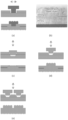
- FIGS. 3 ( a ) to 3 ( g ) and 4 ( a ) to 4 ( e ) show the experimental results of a completely sealed joint of a three-dimensional metal structure (see Patent document 1), which is a unique technique proposed by the present applicant.
- FIGS. 3 ( a ) to 3 ( g ) and 4 ( a ) to 4 ( e ) show vibration in a direction that is parallel to the pressure-applying direction (longitudinal vibration) and vibration in a direction that is orthogonal to the pressure-applying direction (transverse vibration), respectively.
- the experimental results pass the underwater sealing test.
- FIGS. 3 ( a ) and 3 ( b ) each show a state before the joining processing.
- FIGS. 3 ( c ) and 3 ( d ) each show a state after the joining processing.
- a round casing was subjected to the joining processing.
- FIGS. 3 ( e ), 3 ( f ), and 3 ( g ) each show an example of sealing joining of a three-dimensional metal structure formed of aluminum members each having a diameter of 150 mm.
- FIGS. 3 ( f ) and 3 ( g ) shows a case in which the joint portion was not damaged and a case in which the joint portion was damaged, respectively. No trace of fusion was observed in any of the experimental results. That is to say, an ingot is formed by the diffusion joining. Diffusion joining provides such joining using the diffusion of atoms that occurs at the joining surface. For example, the base member is heated and pressed without melting in a state in which it is held. With this, the atoms at the joining interface are diffused across the joining surface, thereby providing a perfect joint portion from the metallurgical viewpoint.
- FIGS. 4 ( a ) to 4 ( e ) each show a state before the joining processing.
- FIGS. 4 ( c ) and 4 ( d ) each show a state after the joining processing.
- a rectangular casing was subjected to the joining processing.
- FIG. 4 ( e ) is a microscopic photograph of the cross section. In the microscopic observation, it is difficult to confirm the joining interface because an ingot is formed by the diffusion joining.
- FIGS. 5 ( a ) to 5 ( e ) and 6 ( a ) to 6 ( f ) each show an example of joining processing according to the present invention.
- FIG. 5 ( a ) shows an example of joining processing using transverse vibration.
- the base member is configured as a pair of plate-shaped members stacked in the vertical direction.
- a through hole is formed in the upper-side plate-shaped member, and there is no hole in the lower-side plate-shaped member. Pressure is applied from the lower side to the lower-side plate-shaped member. In this state, transverse vibration is applied to the head portion of the rivet inserted into the hole so as to provide joining processing.
- FIG. 5 ( b ) shows microscopic observation of the cross section subjected to the joining processing.
- the two plate-shaped members are each formed of HTSS (High Tensile Strength Steel).
- the rivet is formed of iron (steel).
- an ingot is formed by the diffusion joining.
- FIGS. 5 ( c ), 5 ( d ), and 5 ( e ) each show an example of joining processing using transverse vibration.
- the hole has a shape such that, at the surface, the hole size is larger than the tip of the rivet, such that the hole size becomes smaller according to the depth of the hole, and such that, at the deepest position, the hole size is smaller than the tip of the rivet.
- such an arrangement provides a state in which the tip of the rivet is in contact with the side face of the inner side of the hole when the tip of the rivet is inserted into the hole.
- the base member has a structure formed of a pair of the plate-shaped members stacked in the vertical direction.
- FIG. 5 ( c ) shows an example in which a hole is formed such that it passes through the upper-side plate-shaped member, and such that it passes through a part of the lower-side plate-shaped member from its front face.
- FIG. 5 ( d ) shows an example in which a hole is formed such that it passes through the upper-side plate-shaped member, and such that there is no hole in the lower-side plate-shaped member. As shown in FIG. 5 ( d ) , this provides joining processing using longitudinal vibration in the same manner as shown in FIG. 5 ( a ) .
- FIG. 5 ( e ) shows an example in which multiple holes are formed. Each hole is formed such that it passes through the upper-side plate-shaped member, and such that there is no hole in the lower-side plate-shaped member.
- longitudinal vibration is applied to multiple rivets inserted into the multiple holes so as to provide joining processing.
- welding is performed by melting a plastic portion. Accordingly, plastic welding is performed using the melted burrs that occur due to welding and that spread like an adhesive agent with the welded portion as a start point. With the present invention, this is capable of providing diffusion joining over a wide range to which sound waves are transmitted, even outside a portion where energy is concentrated.
- this is capable of providing diffusion joining to a portion interposed between members in addition to a portion interposed between a rivet and a base member. Accordingly, such an arrangement is capable of providing joining processing with rivets each inserted into the corresponding hole. In addition, such an arrangement is capable of providing joining processing between the members via multiple holes, thereby providing sealing joining.
- FIGS. 6 ( a ) to 6 ( f ) an example of joining processing using through holes formed in the base member.
- the base member is formed as a pair of plate-shaped members stacked in the vertical direction, and has through holes.
- FIGS. 6 ( a ) and 6 ( b ) are diagrams showing an example before joining processing and an example after joining processing.
- the upper-side plate-shaped member 51 , the lower-side plate-shaped member 53 , and the rivet 55 are each formed of a metal material.
- the rivet 55 is inserted into the hole from the lower side. Pressure is applied to the head portion of the rivet 55 from the lower side. In this state, sound vibration and/or ultrasound vibration is applied from the upper side to the tip of the body portion of the rivet 55 .
- this provides diffusion joining such that no joint portion can be observed between the rivet 55 and the plate-shaped member 51 .
- This also provides diffusion joining between the plate-shaped member 51 and the plate-shaped member 53 over a region to which the sound vibration and/or ultrasound vibration can be transmitted (e.g., in the vicinity of the hole or the like).
- FIGS. 6 ( c ) and 6 ( f ) each show an example of actual processing.
- a target 57 before joining processing and a target 59 after joining processing are shown.
- FIGS. 6 ( c ) and 6 ( d ) show the target 57 and the target 59 as viewed from the front side and the back side, respectively.
- C indicates a 1000-type aluminum rivet.
- this provides the following functions described below, for example.
- this allows the entire region of the joint portion to be formed as a single body in the form of an ingot or alloy.
- Such an arrangement is capable of providing joining strength that is higher than that provided by swaging without change over time.
- such an arrangement is capable of using both longitudinal vibration and transverse vibration. For example, by using transverse vibration, this supports fixation of a brittle material such as ceramic or the like.
- this is capable of providing simultaneous joining processing for multiple portions. For example, by providing fixation with multiple rivets with a narrow pitch between them, this is capable of providing linear hermetic sealing joining for a three-dimensional (3D) structure.
- the sound vibration and/or the ultrasound vibration can be provided by an apparatus described in Patent documents 2 and 3, for example.
Landscapes
- Engineering & Computer Science (AREA)
- Mechanical Engineering (AREA)
- Pressure Welding/Diffusion-Bonding (AREA)
- Connection Of Plates (AREA)
Abstract
Description
Claims (12)
Applications Claiming Priority (3)
| Application Number | Priority Date | Filing Date | Title |
|---|---|---|---|
| JP2020-084936 | 2020-05-14 | ||
| JP2020084936A JP6957054B1 (en) | 2020-05-14 | 2020-05-14 | Rivet joining method and joining processing equipment |
| PCT/JP2021/018400 WO2021230350A1 (en) | 2020-05-14 | 2021-05-14 | Rivet joining method and joining process device |
Publications (2)
| Publication Number | Publication Date |
|---|---|
| US20230201910A1 US20230201910A1 (en) | 2023-06-29 |
| US12030110B2 true US12030110B2 (en) | 2024-07-09 |
Family
ID=78282091
Family Applications (1)
| Application Number | Title | Priority Date | Filing Date |
|---|---|---|---|
| US17/998,528 Active US12030110B2 (en) | 2020-05-14 | 2021-05-14 | Rivet joining method and joining processing apparatus |
Country Status (4)
| Country | Link |
|---|---|
| US (1) | US12030110B2 (en) |
| JP (1) | JP6957054B1 (en) |
| DE (1) | DE112021002753T5 (en) |
| WO (1) | WO2021230350A1 (en) |
Families Citing this family (1)
| Publication number | Priority date | Publication date | Assignee | Title |
|---|---|---|---|---|
| CN117182464B (en) * | 2023-09-06 | 2025-09-12 | 大连长丰实业总公司 | Method for making comparative test blocks for ultrasonic testing of rivets |
Citations (6)
| Publication number | Priority date | Publication date | Assignee | Title |
|---|---|---|---|---|
| US6503585B1 (en) * | 1998-10-21 | 2003-01-07 | Bayer Aktiengesellschaft | Hollow-chamber lightweight component |
| CN105643090A (en) * | 2016-03-22 | 2016-06-08 | 天津大学 | Ultrasonic metal rivet-welding method for connecting plastic with metal well |
| US20160341234A1 (en) * | 2014-02-04 | 2016-11-24 | Woodwelding Ag | Bonding objects together |
| US20180015568A1 (en) * | 2016-07-12 | 2018-01-18 | Ultex Corporation | Joining method |
| JP2021084118A (en) | 2019-11-26 | 2021-06-03 | 株式会社アルテクス | Mechanical vibration processing device and mechanical vibration processing method |
| JP2021094594A (en) | 2019-12-19 | 2021-06-24 | 株式会社アルテクス | Mechanical vibration processing device and mechanical vibration processing method |
Family Cites Families (2)
| Publication number | Priority date | Publication date | Assignee | Title |
|---|---|---|---|---|
| JP4617560B2 (en) * | 2000-10-31 | 2011-01-26 | 富士電機システムズ株式会社 | Static induction appliance and method for manufacturing the same |
| JP6770022B2 (en) | 2018-06-04 | 2020-10-14 | ファナック株式会社 | Servo amplifier selection device, servo amplifier selection method and program |
-
2020
- 2020-05-14 JP JP2020084936A patent/JP6957054B1/en active Active
-
2021
- 2021-05-14 WO PCT/JP2021/018400 patent/WO2021230350A1/en not_active Ceased
- 2021-05-14 DE DE112021002753.0T patent/DE112021002753T5/en active Pending
- 2021-05-14 US US17/998,528 patent/US12030110B2/en active Active
Patent Citations (9)
| Publication number | Priority date | Publication date | Assignee | Title |
|---|---|---|---|---|
| US6503585B1 (en) * | 1998-10-21 | 2003-01-07 | Bayer Aktiengesellschaft | Hollow-chamber lightweight component |
| US20160341234A1 (en) * | 2014-02-04 | 2016-11-24 | Woodwelding Ag | Bonding objects together |
| JP2017511443A (en) | 2014-02-04 | 2017-04-20 | ウッドウェルディング・アクチェンゲゼルシャフト | Connector and its use |
| CN105643090A (en) * | 2016-03-22 | 2016-06-08 | 天津大学 | Ultrasonic metal rivet-welding method for connecting plastic with metal well |
| US20180015568A1 (en) * | 2016-07-12 | 2018-01-18 | Ultex Corporation | Joining method |
| JP2018008288A (en) | 2016-07-12 | 2018-01-18 | 株式会社アルテクス | Joining method |
| US10478915B2 (en) * | 2016-07-12 | 2019-11-19 | Ultex Corporation | Joining method |
| JP2021084118A (en) | 2019-11-26 | 2021-06-03 | 株式会社アルテクス | Mechanical vibration processing device and mechanical vibration processing method |
| JP2021094594A (en) | 2019-12-19 | 2021-06-24 | 株式会社アルテクス | Mechanical vibration processing device and mechanical vibration processing method |
Non-Patent Citations (2)
| Title |
|---|
| International Search Report for the corresponding application No. PCT/JP2021/018400 dated Aug. 3, 2021, with English translation. |
| Zhang et al.; CN105643090A; Ultrasonic metal rivet-welding method for connecting plastic with metal well; Jun. 8, 2016, EPO English Machine Translation; pp. 1-5 (Year: 2016). * |
Also Published As
| Publication number | Publication date |
|---|---|
| WO2021230350A1 (en) | 2021-11-18 |
| DE112021002753T5 (en) | 2023-03-02 |
| JP6957054B1 (en) | 2021-11-02 |
| JP2021178347A (en) | 2021-11-18 |
| US20230201910A1 (en) | 2023-06-29 |
Similar Documents
| Publication | Publication Date | Title |
|---|---|---|
| Matheny et al. | Ultrasonic welding of metals | |
| US8950458B2 (en) | System and method for mounting ultrasonic tools | |
| US10399175B2 (en) | Systems and methods for improving weld strength | |
| US9346120B1 (en) | Sonotrode apparatus for use in ultrasonic additive manufacturing | |
| JPWO2014126172A1 (en) | Laser welding method and laser welding apparatus | |
| JP2007222925A (en) | Friction stirring and joining method | |
| US20080217379A1 (en) | Method for cohesively bonding metal to a non-metallic substrate | |
| US20100176184A1 (en) | Ultrasonic welding using amplitude profiling | |
| JP2019048307A (en) | Double-acting type friction stir spot joining method | |
| US20180236528A1 (en) | Hybrid workpiece joining | |
| US12030110B2 (en) | Rivet joining method and joining processing apparatus | |
| US11045897B2 (en) | Method and apparatus to form a workpiece employing vibration welding | |
| CN103338890B (en) | For the method welding flat component | |
| JP2008534284A (en) | Tools and methods for assembling metal parts | |
| JP2020116600A (en) | Metal plate joining method, joining device, and joining structure | |
| CN103464907B (en) | Method of connecting sheets by thermal self-pressing | |
| JP5553732B2 (en) | Metal joint | |
| US20230234161A1 (en) | Joining method and joining machine | |
| JP7191657B2 (en) | Clamping method and clamping device | |
| JP2003220482A (en) | Method and apparatus for laser welding | |
| KR20170078362A (en) | Friction welding Apparatus and Method by heating thin metal | |
| JP2013034963A (en) | Booster for ultrasonic vibration, ultrasonic vibration joining apparatus using the booster and ultrasonic vibration welding apparatus using the booster | |
| CN110653468A (en) | Joining device and joining method | |
| JP7382116B2 (en) | Joining method | |
| CN116652434A (en) | Welded joint and method of manufacturing the same |
Legal Events
| Date | Code | Title | Description |
|---|---|---|---|
| AS | Assignment |
Owner name: ULTEX CORPORATION, JAPAN Free format text: ASSIGNMENT OF ASSIGNORS INTEREST;ASSIGNOR:SATO, SHIGERU;REEL/FRAME:061931/0628 Effective date: 20221102 |
|
| FEPP | Fee payment procedure |
Free format text: ENTITY STATUS SET TO UNDISCOUNTED (ORIGINAL EVENT CODE: BIG.); ENTITY STATUS OF PATENT OWNER: SMALL ENTITY |
|
| FEPP | Fee payment procedure |
Free format text: ENTITY STATUS SET TO SMALL (ORIGINAL EVENT CODE: SMAL); ENTITY STATUS OF PATENT OWNER: SMALL ENTITY |
|
| STPP | Information on status: patent application and granting procedure in general |
Free format text: DOCKETED NEW CASE - READY FOR EXAMINATION |
|
| STPP | Information on status: patent application and granting procedure in general |
Free format text: NON FINAL ACTION MAILED |
|
| STPP | Information on status: patent application and granting procedure in general |
Free format text: RESPONSE TO NON-FINAL OFFICE ACTION ENTERED AND FORWARDED TO EXAMINER |
|
| STPP | Information on status: patent application and granting procedure in general |
Free format text: NOTICE OF ALLOWANCE MAILED -- APPLICATION RECEIVED IN OFFICE OF PUBLICATIONS |
|
| STPP | Information on status: patent application and granting procedure in general |
Free format text: PUBLICATIONS -- ISSUE FEE PAYMENT RECEIVED |
|
| STPP | Information on status: patent application and granting procedure in general |
Free format text: PUBLICATIONS -- ISSUE FEE PAYMENT VERIFIED |
|
| STCF | Information on status: patent grant |
Free format text: PATENTED CASE |