US12019206B1 - Simulation device and simulation method for liquid sulfur-gas-water multiphase flow and use thereof in high-temperature and high-pressure gas reservoir with high sulfur content - Google Patents
Simulation device and simulation method for liquid sulfur-gas-water multiphase flow and use thereof in high-temperature and high-pressure gas reservoir with high sulfur content Download PDFInfo
- Publication number
- US12019206B1 US12019206B1 US18/392,659 US202318392659A US12019206B1 US 12019206 B1 US12019206 B1 US 12019206B1 US 202318392659 A US202318392659 A US 202318392659A US 12019206 B1 US12019206 B1 US 12019206B1
- Authority
- US
- United States
- Prior art keywords
- valve
- pressure
- gas
- liquid sulfur
- microfluidic chip
- Prior art date
- Legal status (The legal status is an assumption and is not a legal conclusion. Google has not performed a legal analysis and makes no representation as to the accuracy of the status listed.)
- Active
Links
Images


Classifications
-
- G—PHYSICS
- G01—MEASURING; TESTING
- G01V—GEOPHYSICS; GRAVITATIONAL MEASUREMENTS; DETECTING MASSES OR OBJECTS; TAGS
- G01V9/00—Prospecting or detecting by methods not provided for in groups G01V1/00 - G01V8/00
- G01V9/005—Prospecting or detecting by methods not provided for in groups G01V1/00 - G01V8/00 by thermal methods, e.g. after generation of heat by chemical reactions
-
- E—FIXED CONSTRUCTIONS
- E21—EARTH OR ROCK DRILLING; MINING
- E21B—EARTH OR ROCK DRILLING; OBTAINING OIL, GAS, WATER, SOLUBLE OR MELTABLE MATERIALS OR A SLURRY OF MINERALS FROM WELLS
- E21B47/00—Survey of boreholes or wells
-
- G—PHYSICS
- G01—MEASURING; TESTING
- G01N—INVESTIGATING OR ANALYSING MATERIALS BY DETERMINING THEIR CHEMICAL OR PHYSICAL PROPERTIES
- G01N15/00—Investigating characteristics of particles; Investigating permeability, pore-volume or surface-area of porous materials
- G01N15/08—Investigating permeability, pore-volume, or surface area of porous materials
- G01N15/088—Investigating volume, surface area, size or distribution of pores; Porosimetry
-
- G—PHYSICS
- G06—COMPUTING OR CALCULATING; COUNTING
- G06F—ELECTRIC DIGITAL DATA PROCESSING
- G06F30/00—Computer-aided design [CAD]
- G06F30/20—Design optimisation, verification or simulation
-
- G—PHYSICS
- G06—COMPUTING OR CALCULATING; COUNTING
- G06Q—INFORMATION AND COMMUNICATION TECHNOLOGY [ICT] SPECIALLY ADAPTED FOR ADMINISTRATIVE, COMMERCIAL, FINANCIAL, MANAGERIAL OR SUPERVISORY PURPOSES; SYSTEMS OR METHODS SPECIALLY ADAPTED FOR ADMINISTRATIVE, COMMERCIAL, FINANCIAL, MANAGERIAL OR SUPERVISORY PURPOSES, NOT OTHERWISE PROVIDED FOR
- G06Q50/00—Information and communication technology [ICT] specially adapted for implementation of business processes of specific business sectors, e.g. utilities or tourism
- G06Q50/02—Agriculture; Fishing; Forestry; Mining
-
- G—PHYSICS
- G01—MEASURING; TESTING
- G01N—INVESTIGATING OR ANALYSING MATERIALS BY DETERMINING THEIR CHEMICAL OR PHYSICAL PROPERTIES
- G01N15/00—Investigating characteristics of particles; Investigating permeability, pore-volume or surface-area of porous materials
- G01N15/04—Investigating sedimentation of particle suspensions
-
- G—PHYSICS
- G01—MEASURING; TESTING
- G01N—INVESTIGATING OR ANALYSING MATERIALS BY DETERMINING THEIR CHEMICAL OR PHYSICAL PROPERTIES
- G01N15/00—Investigating characteristics of particles; Investigating permeability, pore-volume or surface-area of porous materials
- G01N15/08—Investigating permeability, pore-volume, or surface area of porous materials
-
- G—PHYSICS
- G01—MEASURING; TESTING
- G01N—INVESTIGATING OR ANALYSING MATERIALS BY DETERMINING THEIR CHEMICAL OR PHYSICAL PROPERTIES
- G01N21/00—Investigating or analysing materials by the use of optical means, i.e. using sub-millimetre waves, infrared, visible or ultraviolet light
- G01N21/01—Arrangements or apparatus for facilitating the optical investigation
- G01N21/03—Cuvette constructions
-
- Y—GENERAL TAGGING OF NEW TECHNOLOGICAL DEVELOPMENTS; GENERAL TAGGING OF CROSS-SECTIONAL TECHNOLOGIES SPANNING OVER SEVERAL SECTIONS OF THE IPC; TECHNICAL SUBJECTS COVERED BY FORMER USPC CROSS-REFERENCE ART COLLECTIONS [XRACs] AND DIGESTS
- Y02—TECHNOLOGIES OR APPLICATIONS FOR MITIGATION OR ADAPTATION AGAINST CLIMATE CHANGE
- Y02P—CLIMATE CHANGE MITIGATION TECHNOLOGIES IN THE PRODUCTION OR PROCESSING OF GOODS
- Y02P20/00—Technologies relating to chemical industry
- Y02P20/141—Feedstock
Definitions
- the present disclosure relates to the field of exploration and development of oil and natural gas, and particularly to a simulation device and simulation method for liquid sulfur-gas-water multiphase flow and use thereof in high-temperature and high-pressure gas reservoir with high sulfur content.
- the temperature of reservoir strata is generally higher than the melting point (119° C.) of sulfur, so that the elemental sulfur is precipitated in a liquid state, on one hand, the elemental sulfur is deposited in pores or throats through adsorption to block gas seepage channels and reduce the permeability of the reservoir stratum; on the other hand, the deposited sulfur forms a mobile phase through aggregation, and forms two-phase seepage with gas, so that the effective permeability of the gas phase is reduced, thereby decreasing the gas well capacity, and affecting the development effect of the gas reservoir.
- the melting point 119° C.
- Gu Shaohua, et al. (refer to Gu Shaohua, Shi Zhiliang, Hu Xiangyang, et al., “An Experimental Study on Gas-liquid Sulfur Two-phase Flow in Ultradeep High-sulfur Gas Reservoirs” [J], NATURE GAS INDUSTRY, 2018, Vol. 38, Issue 10, pp. 70-75) carried out the two-phase displacement experiment of gas-liquid sulfur under the conditions of high-temperature and high-pressure, and processed the experimental data of relative permeability based on the non-steady state method to plot a gas-liquid sulfur relative permeability curve.
- He Linji (“Study on the Law of Gas-Liquid Sulfur Seepage in Gas Reservoirs with High Sulfur Content” [D].
- Southwest Petroleum University, 2017) carried out experimental tests under different temperature and stress-sensitive conditions and plotted a gas-liquid sulfur two-phase relative permeability curve according to the non-steady state method.
- the present disclosure aims to provide a simulation device and simulation method for liquid sulfur-gas-water multiphase flow and use thereof in a high-temperature and high-pressure gas reservoir with high sulfur content, the method can overcome the difficult problem that the whole flow process of liquid sulfur needs to be kept under the high-temperature, high-pressure and safe environment through high-precision visualized micro-fluidic control, and reproduce the multi-phase flow behavior under the constraints of the actual porous medium structure and the in-situ reservoir stratum high-temperature and high-pressure conditions during the three-phase coexistence of liquid sulfur-gas-water, and can provide a theoretical basis for the efficient development of the gas reservoir with high sulfur content.
- the first aspect of the present disclosure provides a simulation device for liquid sulfur-gas-water multiphase flow comprising an injection unit, a high-temperature high-pressure visible reaction kettle 19 , and a data acquisition unit;
- the second aspect of the present disclosure provides a simulation method performed in the aforementioned simulation device for liquid sulfur-gas-water multiphase flow comprising:
- the third aspect of the present disclosure provides a method of using the aforementioned simulation method in the high-temperature and high-pressure gas reservoirs with high sulfur content.
- FIG. 1 illustrates a schematic diagram of the geometric morphology of an etched pore structure in Example 1 of the present disclosure
- FIG. 2 illustrates a schematic diagram of the material object of an etched microfluidic chip in Example 1 of the present disclosure
- FIG. 3 illustrates a schematic diagram of a liquid sulfur-gas-water three-phase microfluidic experimental device in Example 1 of the present disclosure
- FIG. 4 illustrates a schematic diagram of a high-temperature high-pressure saturated liquid sulfur experiment in Example 1 of the present disclosure
- FIG. 5 is a schematic diagram showing the saturated liquid sulfur results of the microfluidic chip in Example 1 of the present disclosure
- FIG. 6 is a schematic diagram of a process of cleaning a pipeline with gas in Example 1 of the present disclosure
- FIG. 7 is a schematic diagram of a simulation experiment of driving liquid sulfur with gas in Example 1 of the present disclosure.
- FIG. 8 illustrates a schematic diagram of the liquid sulfur-nitrogen gas two-phase flow in Example 1 of the present disclosure
- FIG. 9 illustrates a schematic diagram of the process of washing a pipeline with water in Example 1 of the present disclosure
- FIG. 10 illustrates a schematic diagram of a process of driving liquid sulfur with water in Example 1 of the present disclosure
- FIG. 11 is a schematic diagram showing the formation water drive gas-liquid sulfur three-phase occurrence in Example 1 of the present disclosure
- FIG. 12 is a schematic view showing the alternate injection of water and gas in Example 1 of the present disclosure.
- FIG. 13 is a schematic view showing the liquid sulfur-gas-water three-phase occurrence in Example 1 of the present disclosure
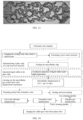
- FIG. 14 is a schematic view showing the flowchart of the simulation method used in Example 1 of the present disclosure.
- FIG. 15 illustrates a schematic diagram of the geometric morphology of an etched pore structure in Example 3 of the present disclosure.
- any valve of the ranges disclosed herein are not limited to the precise ranges or values, such ranges or values shall be comprehended as comprising the values adjacent to the ranges or values.
- numerical ranges the endpoint values of the various ranges, the endpoint values and the individual point valve of the various ranges, and the individual point values may be combined with one another to produce one or more new numerical ranges, which should be deemed have been specifically disclosed herein.
- the first aspect of the present disclosure provides a simulation device for liquid sulfur-gas-water multiphase flow comprising an injection unit, a high-temperature high-pressure visible reaction kettle 19 , and a data acquisition unit;
- an injection pump and three intermediate containers are used for implementing the displacement process of multi-phase fluid, controlling the temperature, the pressure, and the injection flow rate;
- the high-speed camera 15 is used for observing and acquiring the three-phase flow characteristics in a microfluidic chip 18 in the real-time and dynamic manner, and the image processing is performed for analyzing parameters (e.g., a contact angle, an occurrence mode) in the liquid sulfur-gas-water three-phase micro-flow process to obtain the microcosmic seepage characteristics.
- the present disclosure ensures the high temperature condition of the whole process through the thermostatic heater and the heating and heat preservation belt, and realizes the reproduction of the flowing state of the liquid sulfur in an actual formation; on the other hand, a pipeline cleaning device in the experiment process is arranged, the heat-preservation and pressure-maintaining experiment pipeline is cleaned, all steps are not influenced mutually, and the experiment is more accurate; the ring pressure tracking system ensures that not only a high-pressure environment can be realized, but also the microfluidic chip is prevented from being crushed; finally, the real-time monitoring of the whole process is implemented by a high-speed camera, it can reproduce the multi-phase flow behavior under the constraints of the actual porous medium structure and the in-situ reservoir stratum high-temperature and high-pressure conditions during the three-phase coexistence of liquid sulfur-gas-water, and can provide a theoretical basis for the efficient development of the gas reservoir with high sulfur content.
- the tail end of the device is provided with a tail gas treatment device, which can ensure the safety and environmental protection of the whole experiment process.
- the injection unit further comprises an ISCO constant speed and constant pressure pump 1 , and the ISCO constant speed and constant pressure pump 1 is connected with the other end of the intermediate container for performing the constant speed and constant pressure control on the pressure and flow rate of the fluid in the intermediate container.
- the bottoms of the sulfur intermediate container 5 , the water intermediate container 6 , and the gas intermediate container 7 are provided with a valve D 8 , a valve E 9 , and a valve F 10 respectively, the valve D 8 , the valve E 9 and the valve F 10 are respectively connected with the ISCO constant speed and constant pressure pump 1 .
- the tops of the sulfur intermediate container 5 , the water intermediate container 6 , and the gas intermediate container 7 are provided with a valve A 2 , a valve B 3 and a valve C 4 respectively, the valve A 2 , the valve B 3 and the valve C 4 are connected with the three-way valve G 17 .
- the three-way valve G 17 is embedded in the high-temperature high-pressure visible reaction kettle 19 .
- the intermediate container and the connecting pipeline are disposed in a thermostatic heater A 11 .
- the simulation device further comprises an annular pressure unit connected with an annular pressure inlet end of the high-temperature high-pressure visible reaction kettle 19 , the annular pressure unit provides the high-temperature high-pressure visible reaction kettle 19 with an annular pressure.
- the annular pressure unit comprises a ring pressure tracking pump 12 and a pressure gauge, the pressure gauge is disposed on a connecting pipeline between the ring pressure tracking pump 12 and the high-temperature high-pressure visible reaction kettle 19 .
- the pressure gauge includes a pressure gauge A 13 , a pressure gauge B 14 , and a pressure gauge C 16 .
- the simulation device further comprises a back-pressure valve 21 connected with the microfluidic chip 18 ; a back pressure pump 27 is disposed at the other end of the back-pressure valve 21 , and a pressure gauge D 25 is arranged on a pipeline connecting the back-pressure valve 21 with the back pressure pump 27 , wherein the pressure gauge D 25 is used for collecting and monitoring the back pressure.
- an outlet of the back-pressure valve 21 is provided with a fluid recovery device 22 , and the fluid recovery device 22 is used for metering the volume and/or mass of the outlet-end fluid.
- the fluid recovery device 22 is connected to a tail gas treatment bottle 26 through a pipeline.
- the back-pressure valve 21 and the fluid recovery device 22 are disposed in a thermostatic heater B 23 .
- the data acquisition unit further comprises an LED light source 20 disposed directly below the high-temporal high-pressure visible reaction kettle 19 .
- the high-temperature high-pressure visible reaction kettle 19 further comprises a chip holder, an electric heating system, a temperature sensor, a heat conduction inner cavity, and a heat preservation outer cavity.
- the microfluidic chip 18 is fixed in the heat-conducting inner cavity through the chip holder.
- the heat conduction inner cavity and the heat preservation outer cavity are provided with the electric heating system therein, and the electric heating system is connected to the computer 24 through the temperature sensor to monitor temperature change in real-time.
- the second aspect of the present disclosure provides a simulation method performed in the aforementioned simulation device for liquid sulfur-gas-water multiphase flow comprising:
- a simulation method for liquid sulfur-gas-water multiphase flow of the present disclosure includes two methods, wherein one simulation method includes step (1), step (2), step (3), step (4), step (5) and step (6); another simulation method includes step (1), step (2), step (3) and step (7); that is, each simulation experiment is carried out by selecting the steps (1) to (6); or the simulation experiment is performed by selecting the steps (1) to (3) and the step (7), both can produce the simulated state of the liquid sulfur-gas-water three-phase flow.
- the reservoir stratum sample may be derived from an actual carbonate downhole core or a natural outcrop core.
- the natural outcrops refer to the portions of the rock stratum exposed to the earth's surface.
- the method for manufacturing the casting body slice in the present disclosure comprises the following processes: vacuum pouring, high-temperature high-pressure curing, sampling, grinding the slice, covering with the slice, and the like.
- the process of saturating the liquid sulfur in step (2) comprises:
- the process of cleaning the pipeline with nitrogen gas in step (3) comprises:
- the simulation process of the gas drive liquid sulfur in step (4) comprises:
- the process of washing the pipeline with water in step (5) comprises:
- the process of liquid sulfur-gas-water three-phase simulation under the condition of driving the gas-liquid sulfur with water in step (6) comprises:
- the process of liquid sulfur-gas-water three-phase flow simulation under the condition of gas-water alternate injection in step (7) comprises:
- the simulation method further comprises disassembling and reloading the microfluidic chip, specifically, the method for disassembling and reloading the microfluidic chip comprises the following steps:
- the third aspect of the present disclosure provides a use of the aforementioned simulation method in the high-temperature and high-pressure gas reservoirs with high sulfur content.
- the conditions of the high-temperature and high-pressure gas reservoirs with high sulfur content comprise: the temperature condition is within a range of 120-200° C., and the pressure condition is within a range of 1-60 MPa; preferably, the temperature is within a range of 120-180° C., and the pressure is within a range of 20-60 MPa.
- the simulation method comprised the following steps:
- Example 2 After the simulation experiment in Example 1 was finished, the microfluidic chip was disassembled and reloaded.
- Example 2 After the simulation experiment in Example 2 was finished, the microfluidic chip was disassembled and reloaded.
- FIG. 15 illustrated a schematic diagram of the geometric morphology of an etched pore structure in Example 3 of the present disclosure, as can be seen from FIG. 15 , its pore throat size distribution was wider, and the heterogeneity was stronger.
- the simulated state of the liquid sulfur-gas-water three-phase flow can also be obtained, the liquid sulfur-gas-water three-phase existed in the macropore simultaneously, the local fine pore canal was occupied by water or gas, and a lot of the liquid sulfur was distributed on the wall surface and the blind end of the pores.
Landscapes
- Physics & Mathematics (AREA)
- Engineering & Computer Science (AREA)
- Life Sciences & Earth Sciences (AREA)
- General Physics & Mathematics (AREA)
- Chemical & Material Sciences (AREA)
- General Life Sciences & Earth Sciences (AREA)
- Geophysics (AREA)
- Theoretical Computer Science (AREA)
- Mining & Mineral Resources (AREA)
- Chemical Kinetics & Catalysis (AREA)
- Health & Medical Sciences (AREA)
- Business, Economics & Management (AREA)
- General Health & Medical Sciences (AREA)
- Geology (AREA)
- Animal Husbandry (AREA)
- Primary Health Care (AREA)
- Geometry (AREA)
- Agronomy & Crop Science (AREA)
- Evolutionary Computation (AREA)
- Marine Sciences & Fisheries (AREA)
- Computer Hardware Design (AREA)
- Pathology (AREA)
- Economics (AREA)
- Human Resources & Organizations (AREA)
- Marketing (AREA)
- General Engineering & Computer Science (AREA)
- Strategic Management (AREA)
- Tourism & Hospitality (AREA)
- General Business, Economics & Management (AREA)
- Immunology (AREA)
- Environmental & Geological Engineering (AREA)
- Fluid Mechanics (AREA)
- Biochemistry (AREA)
- Analytical Chemistry (AREA)
- Geochemistry & Mineralogy (AREA)
- Dispersion Chemistry (AREA)
- Physical Or Chemical Processes And Apparatus (AREA)
Abstract
The present discloses a simulation device and simulation method for liquid sulfur-gas-water multiphase flow and use thereof in a high-temperature and high-pressure gas reservoir with high sulfur content.
Description
The application claims the benefit of Chinese Application No. 202311446500.3, filed on Nov. 1, 2023, entitled “SIMULATION DEVICE AND SIMULATION METHOD FOR LIQUID SULFUR-GAS-WATER MULTIPHASE FLOW AND USE THEREOF IN HIGH-TEMPERATURE AND HIGH-PRESSURE GAS RESERVOIR WITH HIGH SULFUR CONTENT”, the contents of which is specifically and entirely incorporated herein by reference.
The present disclosure relates to the field of exploration and development of oil and natural gas, and particularly to a simulation device and simulation method for liquid sulfur-gas-water multiphase flow and use thereof in high-temperature and high-pressure gas reservoir with high sulfur content.
China has abundant resources of natural gas with high sulfur content, which is mainly distributed in the Sichuan Basin in southwest China, and has a total amount of more than 1×10¹² m3, thus the development potential is enormous. Compared with the existing natural gas reservoir, the gas reservoir with high sulfur content suffers from precipitation of elemental sulfur during the development process due to the decreased dissolving capacity of elemental sulfur in acid gas as the reservoir pressure is reduced. For deep or ultra-deep reservoir strata, the temperature of reservoir strata is generally higher than the melting point (119° C.) of sulfur, so that the elemental sulfur is precipitated in a liquid state, on one hand, the elemental sulfur is deposited in pores or throats through adsorption to block gas seepage channels and reduce the permeability of the reservoir stratum; on the other hand, the deposited sulfur forms a mobile phase through aggregation, and forms two-phase seepage with gas, so that the effective permeability of the gas phase is reduced, thereby decreasing the gas well capacity, and affecting the development effect of the gas reservoir. In addition, when the gas reservoir development enters the middle and later stages, the water invasion phenomenon causes increased water content in the stratum, and the liquid sulfur-gas-water three-phase seepage occurs, whose flow mechanism is complex. Multiphase flow interaction in gas reservoirs with high sulfur content controls the natural gas extraction process in the development process, wherein whether the liquid sulfur has an influence on the production process under high-temperature and high-pressure conditions has been a pending scientific problem for many years.
At present, the research targeting the gas-liquid sulfur-water three-phase seepage of the deep and ultra-deep gas reservoir strata with high sulfur content has not been reported. In the existing art, a small amount of experimental research aiming at the gas-liquid sulfur two-phase seepage has been carried out.
Gu Shaohua, et al. (refer to Gu Shaohua, Shi Zhiliang, Hu Xiangyang, et al., “An Experimental Study on Gas-liquid Sulfur Two-phase Flow in Ultradeep High-sulfur Gas Reservoirs” [J], NATURE GAS INDUSTRY, 2018, Vol. 38, Issue 10, pp. 70-75) carried out the two-phase displacement experiment of gas-liquid sulfur under the conditions of high-temperature and high-pressure, and processed the experimental data of relative permeability based on the non-steady state method to plot a gas-liquid sulfur relative permeability curve.
Chen Qi (“Study on the Effect of Liquid Sulfur Adsorption of Gas Reservoirs with High Sulfur Content on the Reservoir Stratum” [D]. Southwest Petroleum University, 2019) selected rock cores with different porosities and permeabilities, and carried out the gas-liquid sulfur two-phase seepage experiments under the conditions of altered stress, and obtained a gas-liquid sulfur relative permeability curve under different confining pressure conditions by adopting the non-steady state method.
He Linji (“Study on the Law of Gas-Liquid Sulfur Seepage in Gas Reservoirs with High Sulfur Content” [D]. Southwest Petroleum University, 2017) carried out experimental tests under different temperature and stress-sensitive conditions and plotted a gas-liquid sulfur two-phase relative permeability curve according to the non-steady state method.
To sum up, a few experimental studies related to liquid sulfur seepage have been reported at present due to the limitation of the experimental conditions, and the experimental studies are mainly targeted at the gas-liquid sulfur two-phase seepage experiments. The multi-phase flow behavior under the liquid sulfur-gas-water coexistence state under the real medium space constraint of the gas reservoir stratum with high sulfur content has not been reported, such that the high-efficiency development of the gas reservoirs with high sulfur content and the research progress of the sulfur control and treatment are greatly restricted.
Therefore, it has important significance to research and develop a simulation method and simulation device for liquid sulfur-gas-water multiphase flow of the high-temperature and high-pressure gas reservoir with high sulfur content.
The present disclosure aims to provide a simulation device and simulation method for liquid sulfur-gas-water multiphase flow and use thereof in a high-temperature and high-pressure gas reservoir with high sulfur content, the method can overcome the difficult problem that the whole flow process of liquid sulfur needs to be kept under the high-temperature, high-pressure and safe environment through high-precision visualized micro-fluidic control, and reproduce the multi-phase flow behavior under the constraints of the actual porous medium structure and the in-situ reservoir stratum high-temperature and high-pressure conditions during the three-phase coexistence of liquid sulfur-gas-water, and can provide a theoretical basis for the efficient development of the gas reservoir with high sulfur content.
In order to achieve the above object, the first aspect of the present disclosure provides a simulation device for liquid sulfur-gas-water multiphase flow comprising an injection unit, a high-temperature high-pressure visible reaction kettle 19, and a data acquisition unit;
-
- the injection unit comprises an intermediate container, the intermediate container comprising a sulfur
intermediate container 5, a waterintermediate container 6, and a gasintermediate container 7; - the high-temperature high-pressure
visible reaction kettle 19 comprises amicrofluidic chip 18, and the high-temperature high-pressurevisible reaction kettle 19 is connected with one end of the intermediate connector through a three-way valve G 17, to inject the fluid of the intermediate connector into themicrofluidic chip 18 through a connecting pipeline; - the data acquisition unit comprises a high-
speed camera 15 arranged right above the high-temperature high-pressurevisible reaction kettle 19, and acomputer 24 connected with the high-speed camera 15, in order to observe the fluid changes in themicrofluidic chip 18 with real-time imaging.
- the injection unit comprises an intermediate container, the intermediate container comprising a sulfur
The second aspect of the present disclosure provides a simulation method performed in the aforementioned simulation device for liquid sulfur-gas-water multiphase flow comprising:
-
- a first simulation method:
- (1) production of a microfluidic chip 18:
- 1) manufacturing a casting body slice by extracting a core rock sample from an actual reservoir stratum, and extracting a pore crack structure through microscope imaging;
- 2) etching the microfluidic chip according to the pore crack structure to produce a glass plate etching microscopic model;
- 3) gluing the other glass plate having an injection hole and a fluid extraction hole through vacuum bonding to obtain a
microfluidic chip 18 representing a real reservoir pore structure; - (2) saturating the liquid sulfur in the microfluidic chip 18:
- placing the
microfluidic chip 18 in a high-temperature high-pressurevisible reaction kettle 19, filling a sulfurintermediate container 5 with sulfur powder, heating and melting the sulfur powder to a liquid sulfur state, and injecting the liquid sulfur into themicrofluidic chip 18 at high temperature until the liquid sulfur is saturated; - (3) cleaning the pipeline with nitrogen gas:
- closing the connection route of the
microfluidic chip 18 and the three-way valve 17, and simultaneously opening the branch on the other side, so that the three-way valve 17 is in direct communication with the back-pressure valve 21; nitrogen gas in the gasintermediate container 7 bypasses themicrofluidic chip 18 along the branch and through the three-way valve 17, and directly flows into arecovery device 22 through the back-pressure valve 21 to clean the residual liquid sulfur in the processing pipeline until no liquid sulfur is generated in therecovery device 22; in order to avoid the influence of the liquid sulfur in the pipeline on the sulfur saturation in themicro-fluid control chip 18 when the liquid sulfur is displaced by nitrogen gas; - (4) simulation of gas drive liquid sulfur:
- adjusting a three-
way valve 17, such that the three-way valve 17 is in communication with themicrofluidic chip 18, injecting nitrogen gas into themicrofluidic chip 18, and acquiring a simulated state of gas-liquid sulfur two-phase flow through a high-speed camera 15; - (5) washing the pipeline with water:
- closing the connection route of the three-
way valve 17 and themicrofluidic chip 18, and simultaneously opening the branch on the other side, so that the three-way valve 17 is in direct communication with the back-pressure valve 21; the water in the waterintermediate container 6 bypasses themicrofluidic chip 18 along the branch and through the three-way valve 17, and directly flows into arecovery device 22 through the back-pressure valve 21 to clean the residual gas in the processing pipeline until no obvious bubble is generated in therecovery device 22; in order to avoid the influence of the residual gas in the pipeline on the gas-liquid sulfur saturation in themicrofluidic chip 18 when the residual gas is displaced by water; - (6) liquid sulfur-gas-water three-phase simulation under the condition of driving the gas-liquid sulfur with water:
- adjusting the three-
way valve 17, such that the three-way valve 17 is in communication with themicrofluidic chip 18, injecting distilled water into themicrofluidic chip 18, and acquiring a simulated state of liquid sulfur-gas-water three-phase flow through the high-speed camera 15; - or, a second simulation method:
- the method is performed after steps (1) to (3) of the first simulation method:
- (7) liquid sulfur-gas-water three-phase flow simulation under the condition of gas-water alternate injection:
- the step is performed after steps (1) to (3), alternately opening a water
intermediate container 6 and a gasintermediate container 7 to carry out the gas-water alternate displacement until the stable state, and acquiring a simulated state of liquid sulfur-gas-water three-phase flow through the high-speed camera 15.
The third aspect of the present disclosure provides a method of using the aforementioned simulation method in the high-temperature and high-pressure gas reservoirs with high sulfur content.
Due to the technical scheme, the present disclosure has the following beneficial effects:
-
- (1) The method realizes the liquid sulfur-containing three-phase visualized simulation method for the first time, observes the occurrence state of the liquid sulfur under high-temperature and high-pressure conditions and depicts the interaction process of the liquid sulfur with gas and water;
- (2) The method is safe and feasible, the whole process is kept at the temperature range of 120-180° C. and the pressure range of 20-60 MPa, and reproduces the actual high-temperature and high-pressure conditions of the reservoir stratum;
- (3) The outlet of the device is provided with a sulfur recovery measuring cylinder and an alkali liquor so that the smoothness, safety, and environmental protection of the experiments are ensured;
- (4) The device clearly defines the tracking errors of the internal environment pressure and the injection pressure of the high-temperature high-pressure kettle;
- (5) The arrangement of cleaning pipelines in the device has the advantages that the pipeline can be washed in the heat-preservation and pressure-maintaining experiment process, the steps are not influenced by each other, and the experiment is more accurate.
-
- 1: ISCO constant speed and constant pressure pump;
- 2: Valve A;
- 3: Valve B;
- 4: Valve C;
- 5: Sulfur intermediate container;
- 6: Water intermediate container;
- 7: Gas intermediate container;
- 8: Valve D;
- 9: Valve E;
- 10: Valve F;
- 11: Thermostatic heater A;
- 12: Ring pressure tracking pump;
- 13: Pressure gauge A;
- 14: Pressure gauge B;
- 15: High-speed camera;
- 16: Pressure gauge C;
- 17: Three-way valve G;
- 18 Microfluidic chip;
- 19: High-temperature high-pressure visible reaction kettle;
- 20: LED lamp;
- 21: Back-pressure valve;
- 22: Fluid recovery device;
- 23: Thermostatic heater B;
- 24: Computer;
- 25: Pressure gauge D;
- 26: Tail gas treatment bottle;
- 27: Back pressure pump.
The terminals and any valve of the ranges disclosed herein are not limited to the precise ranges or values, such ranges or values shall be comprehended as comprising the values adjacent to the ranges or values. As for numerical ranges, the endpoint values of the various ranges, the endpoint values and the individual point valve of the various ranges, and the individual point values may be combined with one another to produce one or more new numerical ranges, which should be deemed have been specifically disclosed herein.
As described above, the first aspect of the present disclosure provides a simulation device for liquid sulfur-gas-water multiphase flow comprising an injection unit, a high-temperature high-pressure visible reaction kettle 19, and a data acquisition unit;
-
- the injection unit comprises an intermediate container, the intermediate container comprising a sulfur
intermediate container 5, a waterintermediate container 6, and a gasintermediate container 7; - the high-temperature high-pressure
visible reaction kettle 19 comprises amicrofluidic chip 18, and the high-temperature high-pressurevisible reaction kettle 19 is connected with one end of the intermediate connector through a three-way valve G 17, to inject the fluid of the intermediate connector into themicrofluidic chip 18 through a connecting pipeline; - the data acquisition unit comprises a high-
speed camera 15 arranged right above the high-temperature high-pressurevisible reaction kettle 19, and acomputer 24 connected with the high-speed camera 15, to observe the fluid changes in themicrofluidic chip 18 with real-time imaging.
- the injection unit comprises an intermediate container, the intermediate container comprising a sulfur
The inventors of the present disclosure found that an injection pump and three intermediate containers are used for implementing the displacement process of multi-phase fluid, controlling the temperature, the pressure, and the injection flow rate; the high-speed camera 15 is used for observing and acquiring the three-phase flow characteristics in a microfluidic chip 18 in the real-time and dynamic manner, and the image processing is performed for analyzing parameters (e.g., a contact angle, an occurrence mode) in the liquid sulfur-gas-water three-phase micro-flow process to obtain the microcosmic seepage characteristics.
Furthermore, on one hand, the present disclosure ensures the high temperature condition of the whole process through the thermostatic heater and the heating and heat preservation belt, and realizes the reproduction of the flowing state of the liquid sulfur in an actual formation; on the other hand, a pipeline cleaning device in the experiment process is arranged, the heat-preservation and pressure-maintaining experiment pipeline is cleaned, all steps are not influenced mutually, and the experiment is more accurate; the ring pressure tracking system ensures that not only a high-pressure environment can be realized, but also the microfluidic chip is prevented from being crushed; finally, the real-time monitoring of the whole process is implemented by a high-speed camera, it can reproduce the multi-phase flow behavior under the constraints of the actual porous medium structure and the in-situ reservoir stratum high-temperature and high-pressure conditions during the three-phase coexistence of liquid sulfur-gas-water, and can provide a theoretical basis for the efficient development of the gas reservoir with high sulfur content.
In addition, the tail end of the device is provided with a tail gas treatment device, which can ensure the safety and environmental protection of the whole experiment process.
According to the present disclosure, the injection unit further comprises an ISCO constant speed and constant pressure pump 1, and the ISCO constant speed and constant pressure pump 1 is connected with the other end of the intermediate container for performing the constant speed and constant pressure control on the pressure and flow rate of the fluid in the intermediate container.
According to the present disclosure, the bottoms of the sulfur intermediate container 5, the water intermediate container 6, and the gas intermediate container 7 are provided with a valve D 8, a valve E 9, and a valve F 10 respectively, the valve D 8, the valve E 9 and the valve F 10 are respectively connected with the ISCO constant speed and constant pressure pump 1.
According to the present disclosure, the tops of the sulfur intermediate container 5, the water intermediate container 6, and the gas intermediate container 7 are provided with a valve A 2, a valve B 3 and a valve C 4 respectively, the valve A 2, the valve B 3 and the valve C 4 are connected with the three-way valve G 17.
According to the present disclosure, the three-way valve G 17 is embedded in the high-temperature high-pressure visible reaction kettle 19.
According to the present disclosure, the intermediate container and the connecting pipeline are disposed in a thermostatic heater A 11.
According to the present disclosure, the simulation device further comprises an annular pressure unit connected with an annular pressure inlet end of the high-temperature high-pressure visible reaction kettle 19, the annular pressure unit provides the high-temperature high-pressure visible reaction kettle 19 with an annular pressure.
According to the present disclosure, the annular pressure unit comprises a ring pressure tracking pump 12 and a pressure gauge, the pressure gauge is disposed on a connecting pipeline between the ring pressure tracking pump 12 and the high-temperature high-pressure visible reaction kettle 19.
According to the present disclosure, the pressure gauge includes a pressure gauge A 13, a pressure gauge B 14, and a pressure gauge C 16.
According to the present disclosure, the simulation device further comprises a back-pressure valve 21 connected with the microfluidic chip 18; a back pressure pump 27 is disposed at the other end of the back-pressure valve 21, and a pressure gauge D 25 is arranged on a pipeline connecting the back-pressure valve 21 with the back pressure pump 27, wherein the pressure gauge D 25 is used for collecting and monitoring the back pressure.
According to the present disclosure, an outlet of the back-pressure valve 21 is provided with a fluid recovery device 22, and the fluid recovery device 22 is used for metering the volume and/or mass of the outlet-end fluid.
According to the present disclosure, the fluid recovery device 22 is connected to a tail gas treatment bottle 26 through a pipeline.
According to the present disclosure, the back-pressure valve 21 and the fluid recovery device 22 are disposed in a thermostatic heater B 23.
According to the present disclosure, the data acquisition unit further comprises an LED light source 20 disposed directly below the high-temporal high-pressure visible reaction kettle 19.
According to the present disclosure, the high-temperature high-pressure visible reaction kettle 19 further comprises a chip holder, an electric heating system, a temperature sensor, a heat conduction inner cavity, and a heat preservation outer cavity.
According to the present disclosure, the microfluidic chip 18 is fixed in the heat-conducting inner cavity through the chip holder.
According to the present disclosure, the heat conduction inner cavity and the heat preservation outer cavity are provided with the electric heating system therein, and the electric heating system is connected to the computer 24 through the temperature sensor to monitor temperature change in real-time.
The second aspect of the present disclosure provides a simulation method performed in the aforementioned simulation device for liquid sulfur-gas-water multiphase flow comprising:
-
- a first simulation method:
- (1) production of a microfluidic chip 18:
- 1) manufacturing a casting body slice by extracting a core rock sample from an actual reservoir stratum, and extracting a pore crack structure through microscope imaging;
- 2) etching the microfluidic chip according to the pore crack structure to produce a glass plate etching microscopic model;
- 3) gluing the other glass plate having an injection hole and a fluid extraction hole through vacuum bonding to obtain a
microfluidic chip 18 representing a real reservoir pore structure; - (2) saturating the liquid sulfur in the microfluidic chip 18:
- placing the
microfluidic chip 18 in a high-temperature high-pressurevisible reaction kettle 19, filling a sulfurintermediate container 5 with sulfur powder, heating and melting the sulfur powder to a liquid sulfur state, and injecting the liquid sulfur into themicrofluidic chip 18 at high temperature until the liquid sulfur is saturated; - (3) cleaning the pipeline with nitrogen gas:
- closing the connection route of the
microfluidic chip 18 and the three-way valve 17, and simultaneously opening the branch on the other side, so that the three-way valve 17 is in direct communication with the back-pressure valve 21; nitrogen gas in the gasintermediate container 7 bypasses themicrofluidic chip 18 along the branch and through the three-way valve 17, and directly flows into arecovery device 22 through the back-pressure valve 21 to clean the residual liquid sulfur in the processing pipeline until no liquid sulfur is generated in therecovery device 22, to avoid the influence of the liquid sulfur in the pipeline on the sulfur saturation in themicro-fluid control chip 18 when the liquid sulfur is displaced by nitrogen gas; - (4) simulation of gas drive liquid sulfur:
- adjusting a three-
way valve 17, such that the three-way valve 17 is in communication with themicrofluidic chip 18, injecting nitrogen gas into themicrofluidic chip 18, and acquiring a simulated state of gas-liquid sulfur two-phase flow through a high-speed camera 15; - (5) washing the pipeline with water:
- closing the connection route of the three-
way valve 17 and themicrofluidic chip 18, and simultaneously opening the branch on the other side, so that the three-way valve 17 is in direct communication with the back-pressure valve 21; the water in the waterintermediate container 6 bypasses themicrofluidic chip 18 along the branch and through the three-way valve 17, and directly flows into arecovery device 22 through the back-pressure valve 21 to clean the residual gas in the processing pipeline until no obvious bubble is generated in therecovery device 22, to avoid the influence of the residual gas in the pipeline on the gas-liquid sulfur saturation in themicrofluidic chip 18 when the residual gas is displaced by water; - (6) liquid sulfur-gas-water three-phase simulation under the condition of driving the gas-liquid sulfur with water:
- adjusting the three-
way valve 17, such that the three-way valve 17 is in communication with themicrofluidic chip 18, injecting distilled water into themicrofluidic chip 18, and acquiring a simulated state of liquid sulfur-gas-water three-phase flow through the high-speed camera 15; - or, a second simulation method:
- the method is performed after steps (1) to (3) of the first simulation method:
- (7) liquid sulfur-gas-water three-phase flow simulation under the condition of gas-water alternate injection:
- the step is performed after steps (1) to (3), alternately opening a water
intermediate container 6 and a gasintermediate container 7 to carry out the gas-water alternate displacement until the stable state, and acquiring a simulated state of liquid sulfur-gas-water three-phase flow through the high-speed camera 15.
It shall be noted in the present disclosure that a simulation method for liquid sulfur-gas-water multiphase flow of the present disclosure includes two methods, wherein one simulation method includes step (1), step (2), step (3), step (4), step (5) and step (6); another simulation method includes step (1), step (2), step (3) and step (7); that is, each simulation experiment is carried out by selecting the steps (1) to (6); or the simulation experiment is performed by selecting the steps (1) to (3) and the step (7), both can produce the simulated state of the liquid sulfur-gas-water three-phase flow.
According to the present disclosure, the reservoir stratum sample may be derived from an actual carbonate downhole core or a natural outcrop core. Wherein the natural outcrops refer to the portions of the rock stratum exposed to the earth's surface.
In addition, the method for manufacturing the casting body slice in the present disclosure comprises the following processes: vacuum pouring, high-temperature high-pressure curing, sampling, grinding the slice, covering with the slice, and the like.
According to the present disclosure, the process of saturating the liquid sulfur in step (2) comprises:
-
- 1) maintaining all valves in a closed state, and keeping the three-
way valve G 17 in communication with themicrofluidic chip 18; - 2) filling a sulfur
intermediate container 5 with sulfur powder; - 3) setting the pressure of the back-
pressure valve 21 to be within a range of 25-60 MPa, and keeping the back pressure stable through real-time detection with thepressure gauge 25; - 4) correlating the pressure of a high-temperature high-pressure visible reaction kettle controlled by the
pressure gauge A 13 with the pressure of an injection end controlled by the pressure gauge B 14, and maintaining the pressure difference to be always less than 0.2 MPa; - 5) controlling the temperature of the
thermostatic heater A 11, the high-temperature high-pressurevisible reaction kettle 19, and thethermostatic heater B 23 to be within a range of 120-180° C. and preserving the constant temperature for 3-6 hours; - 6) sequentially opening the
valve 8 andvalve 2, starting the ISCO constant speed andconstant pressure pump 1, injecting in a constant pressure mode, wherein the pressure set valve is 1-2 MPa lower than the back-pressure valve 21 in step 3); then switching to a constant speed injection mode, wherein the speed is set to be within a range of 0.05-0.1 mL/min; - 7) switching on a high-
speed camera 15, starting a video recording mode, observing the liquid sulfur saturation condition, terminating the liquid sulfur saturation by taking an indicator that there is no obvious bubble in themicrofluidic chip 18, stopping the injection of said ISCO constant speed andconstant pressure pump 1, and closing thevalve 8 and thevalve 2.
- 1) maintaining all valves in a closed state, and keeping the three-
According to the present disclosure, the process of cleaning the pipeline with nitrogen gas in step (3) comprises:
-
- 1) keeping all settings in the state of step (2);
- 2) adjusting all valves to be in a closed state, adjusting the connection route of the three-
way valve 17 and themicrofluidic chip 18 to a closed state, and simultaneously opening the branch on the other side, so that the three-way valve 17 is in direct communication with the back-pressure valve 21; bypassing themicrofluidic chip 18; - 3) sequentially opening a
valve 10 and avalve 4, starting the ISCO constant speed andconstant pressure pump 1, injecting in a constant speed mode, and setting the speed to be within a range of 0.1-0.5 mL/min; - 4) stopping the cleaning process until observing that there is no obvious generation of liquid sulfur in the liquid sulfur recovery device, closing the injection of the ISCO constant speed and
constant pressure pump 1, and closing thevalve 10 and thevalve 4.
According to the present disclosure, the simulation process of the gas drive liquid sulfur in step (4) comprises:
-
- 1) keeping all settings in the state of step (3);
- 2) adjusting all valves to be in a closed state, and adjusting a three-
way valve G 17 to be in communication with themicrofluidic chip 18; - 3) sequentially opening a
valve 10 and avalve 4, starting the ISCO constant speed andconstant pressure pump 1, injecting in a constant speed mode, and setting the speed to be within a range of 0.05-0.1 mL/min; - 4) stopping the gas drive liquid sulfur simulation experiment upon detecting that the sulfur-containing saturation of the
microfluidic chip 18 does not change by an image analysis means, closing the injection of the ISCO constant speed andconstant pressure pump 1, closing thevalve 10 and thevalve 4, and obtaining the simulated state of gas-liquid sulfur two-phase flow.
According to the present disclosure, the process of washing the pipeline with water in step (5) comprises:
-
- (1) keeping all settings in the state of step (4);
- (2) adjusting all valves to be in a closed state, adjusting the connection route of the three-
way valve 17 and themicrofluidic chip 18 to a closed state, and simultaneously opening the branch on the other side, so that the three-way valve 17 is in direct communication with the back-pressure valve 21; bypassing themicrofluidic chip 18; - (3) sequentially opening a
valve 9 and avalve 3, starting the ISCO constant speed andconstant pressure pump 1, injecting in a constant speed mode, and setting the speed to be within a range of 0.1-0.5 mL/min; - (4) stopping the cleaning process until observing that there is no obvious generation of bubbles in the liquid sulfur recovery device, closing the injection of the ISCO constant speed and
constant pressure pump 1, and closing thevalve 9 and thevalve 3.
According to the present disclosure, the process of liquid sulfur-gas-water three-phase simulation under the condition of driving the gas-liquid sulfur with water in step (6) comprises:
-
- 1) keeping all settings in the state of step (5);
- 2) adjusting all valves to be in a closed state, and adjusting a three-
way valve G 17 to be in communication with themicrofluidic chip 18; - 3) sequentially opening a
valve 9 and avalve 3, starting the ISCO constant speed andconstant pressure pump 1, injecting in a constant speed mode, and setting the speed to be within a range of 0.05-0.1 mL/min; - 4) stopping the water drive liquid sulfur simulation experiment upon detecting that the sulfur-containing saturation of the
microfluidic chip 18 does not change by an image analysis means, closing the ISCO constant speed andconstant pressure pump 1, closing thevalve 9 and thevalve 3, and obtaining the simulated state of liquid sulfur-gas-water three-phase flow under the water drive gas-liquid sulfur condition.
According to the present disclosure, the process of liquid sulfur-gas-water three-phase flow simulation under the condition of gas-water alternate injection in step (7) comprises:
-
- 1) keeping all settings in the state of step (3);
- 2) adjusting all valves to be in a closed state, and adjusting a three-
way valve G 17 to be in communication with themicrofluidic chip 18; - 3) sequentially opening a
valve 10 and avalve 4, starting the ISCO constant speed andconstant pressure pump 1, injecting in a constant speed mode, and setting the speed to be within a range of 0.05-0.1 mL/min; - 4) after injection for 50-100 min, pausing the ISCO constant speed and
constant pressure pump 1, sequentially closingvalve 10 andvalve 4, openingvalve 9 andvalve 3 in sequence, starting the ISCO constant speed andconstant pressure pump 1, and injecting in a constant speed mode, and setting the speed to be within a range of 0.05-0.1 mL/min; - 5) after injection for 50-100 min, pausing the injection of said ISCO constant speed and
constant pressure pump 1, sequentially closing thevalve 9 and thevalve 3, opening thevalve 10 and thevalve 4 in sequence, starting the ISCO constant speed andconstant pressure pump 1, and injecting in a constant speed mode, and setting the speed to be within a range of 0.05-0.1 mL/min; - 6) circulating step (4) and step (5) in sequence, stopping the liquid sulfur-gas-water three-phase flow simulation experiment upon detecting that the sulfur-containing saturation of the
microfluidic chip 18 does not change by an image analysis means, closing the ISCO constant speed andconstant pressure pump 1, and closing all valves.
According to the present disclosure, the simulation method further comprises disassembling and reloading the microfluidic chip, specifically, the method for disassembling and reloading the microfluidic chip comprises the following steps:
-
- (1) keeping all valves in a closed state, maintaining the connection route between the three-
way valve G 17 and themicrofluidic chip 18 in a closed state, simultaneously opening the branch on the other side, keeping thepump 12 in a running state, and maintaining the tracking error between thepressure gauge 13 and the pressure gauge 14 to be less than 0.1 MPa; - (2) closing the heating device of the high-temperature high-pressure
visible reaction kettle 19, and carrying out the next operation when the temperature is reduced to below 40° C.; - (3) reducing the pressure of the back-
pressure valve 21 at a depressurization rate of 1 MPa/10 min, then disassembling and reloading the microfluidic chip after the pressure of the back-pressure valve is completely released.
- (1) keeping all valves in a closed state, maintaining the connection route between the three-
The third aspect of the present disclosure provides a use of the aforementioned simulation method in the high-temperature and high-pressure gas reservoirs with high sulfur content.
According to the present disclosure, the conditions of the high-temperature and high-pressure gas reservoirs with high sulfur content comprise: the temperature condition is within a range of 120-200° C., and the pressure condition is within a range of 1-60 MPa; preferably, the temperature is within a range of 120-180° C., and the pressure is within a range of 20-60 MPa.
The present disclosure will be described in detail below with reference to examples.
In the following examples:
-
- the high-speed camera with the model number Phantom T1340 was purchased from Vision Research Inc. in the United States of America (USA);
- the saturation parameter was measured by an image analysis method; the rock core slice material was prepared by coring the actual reservoir stratum. The raw material of the sulfur sample was high-purity sulfur powder which was commercially available from Shanghai Hushi Laboratory Equipment Co., Ltd., the purity was larger than 99.999%.
According to the flowchart schematic view of the simulation method in the present disclosure shown in FIG. 14 , specifically, the simulation method comprised the following steps:
-
- S1, production of a microfluidic chip:
- (1) a
rock core 1 of an actual reservoir stratum of the Puguang Gas Field in China was selected to produce a casting body slice to obtain a pore structure plan view as shown inFIG. 1 , whereinFIG. 1 illustrated a schematic diagram of the geometric morphology of an etched pore structure in Example 1 of the present disclosure, as can be seen fromFIG. 1 , the carbonate rock reservoir stratum had a complex pore structure, and the pore throat size was mainly distributed in the range of 10-400 μm; - (2) the microfluidic chip had the dimensions of 75 mm×75 mm×3 mm, and the width of both the inlet end and the outlet end was 1 mm;
- (3) the Borofloat-33 glass was selected to make a model, as shown in
FIG. 2 , whereinFIG. 2 illustrated a schematic diagram of the material object of an etched microfluidic chip in Example 1 of the present disclosure, wherein an etching region of the micro model was 5.722 mm×2.182 mm, the chip depth was an average size 50 μm of an actual pore structure, a pore throat size was distributed between 10 μm and 400 μm, and the minimum pore throat size was 10 μm. - S2, saturating the liquid sulfur at high temperature and high pressure:
- (1) a microfluidic chip was mounted in a high-temperature high-pressure
visible reaction kettle 19, all valves were kept in a closed state, thevalve 17 was kept in communication with themicrofluidic chip 18, a simulation device shown inFIG. 3 was adopted, whereinFIG. 3 illustrated a schematic diagram of a liquid sulfur-gas-water three-phase microfluidic experimental device in the present disclosure; - (2) the
intermediate container 5 was filled with sulfur powder; - (3) the pressure of the back-pressure valve was set at 50 MPa, and the back pressure was kept stable through real-time detection of a
pressure gauge 25; - (4) the pressure of a high-temperature high-pressure visible
reaction kettle pressure 13 was correlated with the pressure of an injection end 14, and the pressure difference was kept always less than 0.2 MPa; - (5) the
thermostatic heater 11, the high-temperature high-pressurevisible reaction kettle 19, and thethermostatic heater 23 were heated to 150° C., and the constant temperature was kept for 3 hours; - (6) the
valve 8 andvalve 2 were sequentially opened, theinjection pump 1 was started, and an injecting was performed in a constant pressure mode, the pressure set valve was 1 MPa lower than the pressure valve of the back-pressure valve 21 in the step (3); the injection was then switched to a constant speed mode, the speed was set to 0.05 mL/min, as shown inFIG. 4 , whereinFIG. 4 illustrated a schematic diagram of a high-temperature high-pressure saturated liquid sulfur experiment in Example 1; - (7) the high-
speed camera 15 was powered on to start the recording mode, the liquid sulfur saturation condition was stopped, and the saturation of liquid sulfur was terminated using an indicator that there was no obvious bubble in themicrofluidic chip 18, as shown inFIG. 5 , whereinFIG. 5 was a schematic diagram showing the saturated liquid sulfur results of the microfluidic chip in Example 1, as can be seen fromFIG. 5 , the liquid sulfur was golden yellow and filled the pores and channels of the whole etched region. Thepump 1 was closed, both thevalve 8 and thevalve 2 were closed. - S3, cleaning the pipeline with nitrogen gas.
- (1) on the basis of S2, all the settings were kept to maintain the state of S2;
- (2) all valves were adjusted to be in a closed state, the connection route between the three-
way valve 17 and themicrofluidic chip 18 was closed, and the branch on the other side was simultaneously opened so that the three-way valve 17 was in direct communication with the back-pressure valve 21; - (3) the
valve 10 and thevalve 4 were sequentially opened, theinjection pump 1 was started, and an injection was performed in a constant speed mode, and the speed was set at 0.1 mL/min; - (4) the cleaning was stopped and pump 1 was powered off until the observation that there was no obvious sulfur generated in the
recovery device 22, bothvalve 10 andvalve 4 were closed, as shown inFIG. 6 , whereinFIG. 6 was a schematic diagram of a process of cleaning pipeline with nitrogen gas in Example 1. - S4, simulation of gas drive liquid sulfur:
- (1) on the basis of S3, all the settings were kept to maintain the state of S3;
- (2) all valves were adjusted to be in a closed state, the three-
way valve 17 was adjusted to be in communication with themicrofluidic chip 18; - (3) the
valve 10 andvalve 4 were sequentially opened, theinjection pump 1 was started, and an injection was performed in a constant speed mode, and the speed was set at 0.05 mL/min, as shown inFIG. 7 , whereinFIG. 7 was a schematic diagram of a simulation experiment of driving liquid sulfur with gas in Example 1; - (4) the gas drive liquid sulfur simulation experiment was stopped when detecting that the
microfluidic chip 18 had no change in sulfur saturation by an image analysis means, the injection pump was shut off, both thevalve 10 and thevalve 4 were stopped, the simulated state of gas-liquid sulfur two-phase flow was shown inFIG. 8 , whereinFIG. 8 illustrated a schematic diagram of the liquid sulfur-nitrogen gas two-phase flow in Example 1; as can be seen fromFIG. 8 : the nitrogen gas drove the liquid sulfur to flow, the two-phase of liquid sulfur and nitrogen gas existed simultaneously, and the liquid sulfur was prone to stagnate at the blind end of the pore, the wall surface, and a portion of the throat with poor connectivity. - S5, washing the pipeline with water:
- (1) on the basis of S4, all the settings were kept to maintain the state of S4;
- (2) all valves were adjusted to be in a closed state, the connection route between the three-
way valve 17 and themicrofluidic chip 18 was closed, and the branch on the other side was simultaneously opened so that the three-way valve 17 was in direct communication with the back-pressure valve 21; - (3) the
valve 9 and thevalve 3 were sequentially opened, theinjection pump 1 was started, and an injection was performed in a constant speed mode, and the speed was set at 0.1 mL/min; - (4) the washing operation was stopped until observing that there was no significant sulfur generation in the
recovery device 22, an injection of thepump 1 was shut off, thevalve 9 and thevalve 3 were closed, as shown inFIG. 9 , whereinFIG. 9 illustrated a schematic diagram of a process of washing pipeline with water in Example 1. - S6, liquid sulfur-gas-water three-phase simulation under the condition of driving the gas-liquid sulfur with water:
- (1) on the basis of S5, all the settings were kept to maintain the state of S5;
- (2) all valves were adjusted to be in a closed state, the three-
way valve 17 was adjusted to be in communication with the microfluidic chip (18); - (3) the
valve 9 andvalve 3 were sequentially opened, theinjection pump 1 was started, and an injection was performed in a constant speed mode, and the speed was set at 0.05 mL/min, as shown inFIG. 10 , whereinFIG. 10 illustrated a schematic diagram of a process of driving liquid sulfur with water in Example 1; - (4) the experiment of water drive liquid sulfur was stopped when detecting that the
microfluidic chip 18 had no change in sulfur saturation by an image analysis means, the injection pump was shut off, both thevalve 9 and thevalve 3 were stopped until only blue formation water was produced at the outlet end of the channel. The final simulated state of the water-liquid sulfur-gas three-phase flow was shown inFIG. 11 , whereinFIG. 11 was a schematic diagram showing the formation water drive gas-liquid sulfur three-phase occurrence in Example 1; as can be seen fromFIG. 11 , the injection of water drove the nitrogen gas and the liquid sulfur to flow, a portion of the liquid sulfur still retained on the blind end and the wall surface of the pores, and a small amount of nitrogen gas stagnated in the pores.
In addition, after the simulation experiment in Example 1 was finished, the microfluidic chip was disassembled and reloaded.
-
- (1) all valves were kept in a closed state, the connection route between the three-
way valve G 17 and themicrofluidic chip 18 was maintained in a closed state, the branch on the other side was in an open state simultaneously, thepump 12 was kept running, and the tracking error between thepressure gauge 13 and the pressure gauge 14 was maintained to be less than 0.1 MPa; - (2) the heating device of the high-temperature high-pressure
visible reaction kettle 19 was closed, and the next operation was performed when the temperature was reduced to below 40° C.; - (3) the pressure of the back-
pressure valve 21 was reduced at a depressurization rate of 1 MPa/10 min, and the microfluidic chip was then disassembled and reloaded after the pressure of the back-pressure valve was completely released.
- (1) all valves were kept in a closed state, the connection route between the three-
After the steps “production of a microfluidic chip”, “saturating the liquid sulfur at high temperature and high pressure”, and “cleaning the pipeline with nitrogen gas” were performed according to the same modes as those in the S1, S2, and S3 of Example 1, the following seventh step S7 was performed:
-
- S7, liquid sulfur-gas-water three-phase flow simulation under the condition of gas-water alternate injection:
- (1) all the settings were kept to maintain the state of S3;
- (2) all valves were adjusted to be in a closed state, the three-
way valve 17 was adjusted to be in communication with themicrofluidic chip 18; - (3) the
valve 10 andvalve 4 were sequentially opened, theinjection pump 1 was started, and an injection was performed in a constant speed mode, and the speed was set at 0.1 mL/min, as shown inFIG. 12 , whereinFIG. 12 was a schematic view showing the alternate injection of water and gas in Example 1; - (4) after the injection for 50 min, an operation of the
injection pump 1 was suspended,valve 10 andvalve 4 were sequentially closed,valve 9 andvalve 3 were sequentially opened, theinjection pump 1 was started, an injection was performed in a constant speed mode, and the speed was set at 0.1 mL/min; - (4) after the injection for 50 min, an operation of the
injection pump 1 was suspended, thevalve 9 and thevalve 3 were sequentially closed, thevalve 10 and thevalve 4 were sequentially opened, theinjection pump 1 was started, an injection was performed in a constant speed mode, and the speed was set at 0.1 mL/min; - (6) step (4) and step (5) were sequentially circulated, and the gas drive liquid sulfur simulation experiment was stopped after detecting that there was no change of sulfur saturation in the
microfluidic chip 18 with an image analysis means, the injection pump was shut off, and all valves were closed to obtain a liquid sulfur-gas-water three-phase morphology diagram, as shown inFIG. 13 , whereinFIG. 13 was a schematic view showing the liquid sulfur-gas-water three-phase occurrence prepared with the simulation method in Example 2; as can be seen fromFIG. 13 , the liquid sulfur was distributed at the blind end of pores and the wall surface, water was distributed on the wall surface and a portion of the pores, both the water and the liquid sulfur produced an obvious influence on the gas channel.
In addition, after the simulation experiment in Example 2 was finished, the microfluidic chip was disassembled and reloaded.
-
- (1) all valves were kept in a closed state, the three-
way valve G 17 and themicrofluidic chip 18 were maintained in a closed state, thepump 12 was kept running, and the tracking error between thepressure gauge 13 and the pressure gauge 14 was maintained to be less than 0.1 MPa; - (2) the heating device of the high-temperature high-pressure
visible reaction kettle 19 was closed, and the next operation was performed when the temperature was reduced to below 40° C.; - (3) the pressure of the back-
pressure valve 21 was reduced at a depressurization rate of 1 MPa/10 min, and the microfluidic chip was then disassembled and reloaded after the pressure of the back-pressure valve was completely released.
- (1) all valves were kept in a closed state, the three-
The liquid sulfur-gas-water three-phase simulation was performed with the same simulation device and simulation method as those in Example 1, except that:
-
- in S1, the production process of a microfluidic chip:
- (1) “A
rock core 1 of an actual reservoir stratum of the Puguang Gas Field” was replaced with “arock core 2 of other carbonate rock reservoir stratum”; compared with “therock core 1 of an actual reservoir stratum of the Puguang Gas Field” in Example 1, the structure of saidrock core 2 of other carbonate rock reservoir stratum had obvious heterogeneity, and the pore throat size was mainly distributed within the range of 10-800 μm; - (2) the microfluidic chip had the dimensions of 75 mm×75 mm×3 mm, and the width of both the inlet end and the outlet end was 1 mm;
- (3) the Borofloat-33 glass was selected to make a model, wherein an etching region of the micro model was 4.404 mm×2.916 mm, the chip depth was an average size of 100 μm of an actual pore structure, a pore throat size was distributed between 10 μm and 800 μm.
In addition, FIG. 15 illustrated a schematic diagram of the geometric morphology of an etched pore structure in Example 3 of the present disclosure, as can be seen from FIG. 15 , its pore throat size distribution was wider, and the heterogeneity was stronger.
In S2, saturating the liquid sulfur at high temperature and high pressure,
-
- wherein:
- (5) the
thermostatic heater 11, the high-temperature high-pressurevisible reaction kettle 19, and thethermostatic heater 23 were heated to 150° C., and the constant temperature was kept for 3 hours; - (6) the
valve 8 andvalve 2 were sequentially opened, theinjection pump 1 was started, and an injection was performed in a constant pressure mode, the pressure was set at 50 MPa; the injection was then switched to a constant speed mode, the speed was set to 0.05 mL/min.
As a result, the simulated state of the liquid sulfur-gas-water three-phase flow can also be obtained, the liquid sulfur-gas-water three-phase existed in the macropore simultaneously, the local fine pore canal was occupied by water or gas, and a lot of the liquid sulfur was distributed on the wall surface and the blind end of the pores.
The above content describes in detail the preferred embodiments of the present disclosure, but the present disclosure is not limited thereto. A variety of simple modifications can be made in regard to the technical solutions of the present disclosure within the scope of the technical concept of the present disclosure, including a combination of individual technical features in any other suitable manner, such simple modifications and combinations thereof shall also be regarded as the content disclosed by the present disclosure, each of them falls into the protection scope of the present disclosure.
Claims (15)
1. A simulation method performed in a simulation device for liquid sulfur-gas-water multiphase flow comprising:
a first simulation method:
(1) production of a microfluidic chip:
1) manufacturing a casting body slice by extracting a core rock sample from an actual reservoir stratum, and extracting a pore crack structure through microscope imaging;
2) etching the microfluidic chip according to the pore crack structure to produce a glass plate etching microscopic model;
3) gluing the other glass plate having an injection hole and a fluid extraction hole through vacuum bonding to obtain a microfluidic chip representing a real reservoir pore structure;
(2) saturating the liquid sulfur in the microfluidic chip:
placing the microfluidic chip in a high-temperature high-pressure visible reaction kettle, filling a sulfur intermediate container with sulfur powder, heating and melting the sulfur powder to a liquid sulfur state, and injecting the liquid sulfur into the microfluidic chip at high temperature until the liquid sulfur is saturated;
(3) cleaning the pipeline with nitrogen gas:
closing the connection route of the microfluidic chip and the three-way valve, and simultaneously opening the branch on the other side, so that the three-way valve is in direct communication with the back-pressure valve; nitrogen gas in the gas intermediate container bypasses the microfluidic chip along the branch and through the three-way valve, and directly flows into a recovery device through the back-pressure valve to clean the residual liquid sulfur in the processing pipeline until no liquid sulfur is generated in the recovery device; to avoid the influence of the liquid sulfur in the pipeline on the sulfur saturation in the micro-fluid control chip when the liquid sulfur is displaced by nitrogen gas;
(4) simulation of gas drive liquid sulfur:
adjusting a three-way valve, such that the three-way valve is in communication with the microfluidic chip, injecting nitrogen gas into the microfluidic chip, and acquiring a simulated state of gas-liquid sulfur two-phase flow through a high-speed camera;
(5) washing the pipeline with water:
closing the connection route of the three-way valve and the microfluidic chip, and simultaneously opening the branch on the other side, so that the three-way valve is in direct communication with the back-pressure valve; the water in the water intermediate container bypasses the microfluidic chip along the branch and through the three-way valve, and directly flows into a recovery device through the back-pressure valve to clean the residual gas in the processing pipeline until no obvious bubble is generated in the recovery device; to avoid the influence of the residual gas in the pipeline on the gas-liquid sulfur saturation in the microfluidic chip when the residual gas is displaced by water;
(6) liquid sulfur-gas-water three-phase simulation under the condition of driving the gas-liquid sulfur with water:
adjusting the three-way valve, such that the three-way valve is in communication with the microfluidic chip, injecting distilled water into the microfluidic chip, and acquiring a simulated state of liquid sulfur-gas-water three-phase flow through the high-speed camera;
or, a second simulation method:
the method is performed after steps (1) to (3) of the first simulation method:
(7) liquid sulfur-gas-water three-phase flow simulation under the condition of gas-water alternate injection:
the step is performed after steps (1) to (3), alternately opening a water intermediate container and a gas intermediate container to carry out the gas-water alternate displacement until the stable state, and acquiring a simulated state of liquid sulfur-gas-water three-phase flow through the high-speed camera;
the simulation device for liquid sulfur-gas-water multiphase flow comprising an injection unit, a high-temperature high-pressure visible reaction kettle, and a data acquisition unit;
the injection unit comprises an intermediate container, the intermediate container comprising a sulfur intermediate container, a water intermediate container, and a gas intermediate container;
the high-temperature high-pressure visible reaction kettle comprises a microfluidic chip, and the high-temperature high-pressure visible reaction kettle is connected with one end of the intermediate connector through a three-way valve G, to inject the fluid of the intermediate connector into the microfluidic chip through a connecting pipeline;
the data acquisition unit comprises a high-speed camera arranged right above the high-temperature high-pressure visible reaction kettle, and a computer connected with the high-speed camera, in order to observe the fluid changes in the microfluidic chip with real-time imaging.
2. The simulation method of claim 1 , wherein the process of saturating the liquid sulfur in step (2) comprises:
1) maintaining all valves in a closed state, and keeping the three-way valve G in communication with the microfluidic chip;
2) filling a sulfur intermediate container with sulfur powder;
3) setting the pressure of the back-pressure valve to be within a range of 25-60 MPa, and keeping the back pressure stable through real-time detection with the pressure gauge;
4) correlating the pressure of a high-temperature high-pressure visible reaction kettle controlled by the pressure gauge A with the pressure of an injection end controlled by the pressure gauge B, and maintaining the pressure difference to be always less than 0.2 MPa;
5) controlling the temperature of the thermostatic heater A, the high-temperature high-pressure visible reaction kettle, and the thermostatic heater B to be within a range of 120-180° C. and preserving the constant temperature for 3-6 hours;
6) sequentially opening the valve and valve, starting the ISCO constant speed and constant pressure pump, injecting in a constant pressure mode, wherein the pressure set valve is 1-2 MPa lower than the back-pressure valve in step 3); then switching to a constant speed injection mode, wherein the speed is set to be within a range of 0.05-0.1 mL/min;
7) switching on a high-speed camera, starting a video recording mode, observing the liquid sulfur saturation condition, terminating the liquid sulfur saturation by taking an indicator that there is no obvious bubble in the microfluidic chip, stopping the injection of said ISCO constant speed and constant pressure pump, and closing the valve and the valve.
3. The simulation method of claim 1 , wherein the process of cleaning the pipeline with nitrogen gas in step (3) comprises:
1) keeping all settings in the state of step (2);
2) adjusting all valves to be in a closed state, adjusting the connection route of the three-way valve and the microfluidic chip to a closed state, and simultaneously opening the branch on the other side, so that the three-way valve is in direct communication with the back-pressure valve; bypassing the microfluidic chip;
3) sequentially opening a valve and a valve, starting the ISCO constant speed and constant pressure pump, injecting in a constant speed mode, and setting the speed to be within a range of 0.1-0.5 mL/min;
4) stopping the cleaning process until observing that there is no obvious generation of liquid sulfur in the liquid sulfur recovery device, closing the injection of the ISCO constant speed and constant pressure pump, and closing the valve and the valve.
4. The simulation method of claim 1 , wherein the simulation process of the gas drive liquid sulfur in step (4) comprises:
1) keeping all settings in the state of step (3);
2) adjusting all valves to be in a closed state, and adjusting a three-way valve G to be in communication with the microfluidic chip;
3) sequentially opening a valve and a valve, starting the ISCO constant speed and constant pressure pump, injecting in a constant speed mode, and setting the speed to be within a range of 0.05-0.1 mL/min;
4) stopping the gas drive liquid sulfur simulation experiment upon detecting that the sulfur-containing saturation of the microfluidic chip does not change by an image analysis means, closing the injection of the ISCO constant speed and constant pressure pump, closing the valve and the valve, and obtaining the simulated state of gas-liquid sulfur two-phase flow.
5. The simulation method of claim 1 , wherein the process of washing the pipeline with water in step comprises:
(1) keeping all settings in the state of step (4);
(2) adjusting all valves to be in a closed state, adjusting the connection route of the three-way valve and the microfluidic chip to a closed state, and simultaneously opening the branch on the other side, so that the three-way valve is in direct communication with the back-pressure valve; bypassing the microfluidic chip;
(3) sequentially opening a valve and a valve, starting the ISCO constant speed and constant pressure pump, injecting in a constant speed mode, and setting the speed to be within a range of 0.1-0.5 mL/min;
(4) stopping the cleaning process until observing that there is no obvious generation of bubbles in the liquid sulfur recovery device, closing the injection of the ISCO constant speed and constant pressure pump, and closing the valve and the valve.
6. The simulation method of claim 1 , wherein the process of liquid sulfur-gas-water three-phase simulation under the condition of driving the gas-liquid sulfur with water in step (6) comprises:
1) keeping all settings in the state of step (5);
2) adjusting all valves to be in a closed state, and adjusting a three-way valve G to be in communication with the microfluidic chip;
3) sequentially opening a valve and a valve, starting the ISCO constant speed and constant pressure pump, injecting in a constant speed mode, and setting the speed to be within a range of 0.05-0.1 mL/min;
4) stopping the water drive liquid sulfur simulation experiment upon detecting that the sulfur-containing saturation of the microfluidic chip does not change by an image analysis means, closing the ISCO constant speed and constant pressure pump, closing the valve and the valve, and obtaining the simulated state of liquid sulfur-gas-water three-phase flow under the water drive gas-liquid sulfur condition.
7. The simulation method of claim 1 , wherein the process of liquid sulfur-gas-water three-phase flow simulation under the condition of gas-water alternate injection in step (7) comprises:
1) keeping all settings in the state of step (3);
2) adjusting all valves to be in a closed state, and adjusting a three-way valve G to be in communication with the microfluidic chip;
3) sequentially opening a valve and a valve, starting the ISCO constant speed and constant pressure pump, injecting in a constant speed mode, and setting the speed to be within a range of 0.05-0.1 mL/min;
4) after injection for 50-100 min, pausing the ISCO constant speed and constant pressure pump, sequentially closing valve and valve, opening valve and valve in sequence, starting the ISCO constant speed and constant pressure pump, and injecting in a constant speed mode, and setting the speed to be within a range of 0.05-0.1 mL/min;
5) after injection for 50-100 min, pausing the injection of said ISCO constant speed and constant pressure pump, sequentially closing the valve and the valve, opening the valve and the valve in sequence, starting the ISCO constant speed and constant pressure pump, and injecting in a constant speed mode, and setting the speed to be within a range of 0.05-0.1 mL/min;
6) circulating step (4) and step (5) in sequence, stopping the liquid sulfur-gas-water three-phase flow simulation experiment upon detecting that the sulfur-containing saturation of the microfluidic chip does not change by an image analysis means, closing the ISCO constant speed and constant pressure pump, and closing all valves.
8. A method of using the simulation method of claim 1 in the high-temperature and high-pressure gas reservoirs with high sulfur content.
9. The method of claim 8 , wherein the conditions of the high-temperature and high-pressure gas reservoirs with high sulfur content comprise: the temperature condition is within a range of 120-200° C., and the pressure condition is within a range of 1-60 MPa.
10. The method of claim 9 , wherein the temperature is within a range of 120-180° C., and the pressure is within a range of 20-60 MPa.
11. The method of claim 1 , wherein the injection unit further comprises an ISCO constant speed and constant pressure pump, and the ISCO constant speed and constant pressure pump is connected with the other end of the intermediate container for performing the constant speed and constant pressure control on the pressure and flow rate of the fluid in the intermediate container; wherein the bottoms of the sulfur intermediate container, the water intermediate container, and the gas intermediate container are provided with a valve D, a valve E, and a valve F respectively, the valve D, the valve E and the valve F are respectively connected with the ISCO constant speed and constant pressure pump;
wherein the tops of the sulfur intermediate container, the water intermediate container, and the gas intermediate container are provided with a valve A, a valve B, and a valve C respectively, the valve A, the valve B and the valve C are connected with the three-way valve G;
wherein the three-way valve G is embedded in the high-temperature high-pressure visible reaction kettle;
wherein the three-way valve G is composed of an inlet G1 and two outlets G2 and G3, when the valve is rotated, the inlet G1 is in communication with the outlet G2, or the inlet G1 is in communication with the outlet G3; there is not the circumstance that the inlet G1 is in communication with the outlets G2 and G3 simultaneously or disconnected with the outlets G2 and G3 simultaneously;
wherein the intermediate container and the connecting pipeline are disposed in a thermostatic heater A.
12. The method of claim 1 , wherein the simulation device further comprises an annular pressure unit connected with an annular pressure inlet end of the high-temperature high-pressure visible reaction kettle, the annular pressure unit provides the high-temperature high-pressure visible reaction kettle with an annular pressure;
wherein the annular pressure unit comprises a ring pressure tracking pump and a pressure gauge, the pressure gauge is disposed on a connecting pipeline between the ring pressure tracking pump and the high-temperature high-pressure visible reaction kettle;
wherein the pressure gauge includes a pressure gauge A, a pressure gauge B, and a pressure gauge C.
13. The method of claim 1 , wherein the simulation device further comprises a back-pressure valve connected with the microfluidic chip;
wherein a back pressure pump is disposed at the other end of the back-pressure valve, and a pressure gauge D is arranged on a pipeline connecting the back-pressure valve with the back pressure pump, wherein the pressure gauge D is used for collecting and monitoring the back pressure.
14. The method of claim 1 , wherein an outlet of the back-pressure valve is provided with a fluid recovery device, and the fluid recovery device is used for metering the volume and/or mass of the outlet-end fluid;
wherein the fluid recovery device is connected with a tail gas treatment bottle through a pipeline;
wherein the back-pressure valve and the fluid recovery device are disposed in a thermostatic heater B.
15. The method of claim 1 , wherein the data acquisition unit further comprises an LED light source disposed directly below the high-temporal high-pressure visible reaction kettle;
wherein the high-temperature high-pressure visible reaction kettle further comprises a chip holder, an electric heating system, a temperature sensor, a heat conduction inner cavity, and a heat preservation outer cavity;
wherein the microfluidic chip is fixed in the heat-conducting inner cavity through the chip holder;
wherein the heat conduction inner cavity and the heat preservation outer cavity are provided with the electric heating system therein, and the electric heating system is connected to the computer through the temperature sensor to monitor temperature change in real-time.
Applications Claiming Priority (2)
| Application Number | Priority Date | Filing Date | Title |
|---|---|---|---|
| CN202311446500.3 | 2023-11-01 | ||
| CN202311446500.3A CN117662112B (en) | 2023-11-01 | Liquid sulfur-gas-water multiphase flow simulation device and simulation method and application thereof in high-temperature high-pressure high-sulfur-containing gas reservoir |
Publications (1)
| Publication Number | Publication Date |
|---|---|
| US12019206B1 true US12019206B1 (en) | 2024-06-25 |
Family
ID=90067144
Family Applications (1)
| Application Number | Title | Priority Date | Filing Date |
|---|---|---|---|
| US18/392,659 Active US12019206B1 (en) | 2023-11-01 | 2023-12-21 | Simulation device and simulation method for liquid sulfur-gas-water multiphase flow and use thereof in high-temperature and high-pressure gas reservoir with high sulfur content |
Country Status (1)
| Country | Link |
|---|---|
| US (1) | US12019206B1 (en) |
Cited By (5)
| Publication number | Priority date | Publication date | Assignee | Title |
|---|---|---|---|---|
| US20230358719A1 (en) * | 2016-07-13 | 2023-11-09 | Ams Trace Metals, Inc. | Techniques for toxic metal detection and speciation in aqueous matrices |
| US12130221B1 (en) * | 2023-05-31 | 2024-10-29 | China University of Petroleum—Beijing | Infinitely expandable modular visual device for simulation of flow in porous media |
| CN118914520A (en) * | 2024-07-16 | 2024-11-08 | 西南石油大学 | Experimental device and method for evaluating mutual dissolution expansion of injected composite gas and crude oil |
| CN119757165A (en) * | 2025-03-03 | 2025-04-04 | 东北石油大学三亚海洋油气研究院 | A device and method for analyzing the tortuosity of porous rock seepage channels |
| CN120421060A (en) * | 2025-07-04 | 2025-08-05 | 中国科学技术大学 | Method for preparing microfluidic chip, microscopic visualization experimental device and method |
Citations (10)
| Publication number | Priority date | Publication date | Assignee | Title |
|---|---|---|---|---|
| US20040255649A1 (en) * | 2003-06-19 | 2004-12-23 | Zougari Mohammed I. | Couette device and method to study solids deposition from flowing fluids |
| US20080233018A1 (en) * | 2007-01-23 | 2008-09-25 | Van Dam Robert Michael | Fully-automated microfluidic system for the synthesis of radiolabeled biomarkers for positron emission tomography |
| US20090036668A1 (en) * | 2007-04-12 | 2009-02-05 | Siemens Medical Solutions Usa, Inc. | Microfluidic radiosynthesis system for positron emission tomography biomarkers |
| US20140120537A1 (en) * | 2012-10-29 | 2014-05-01 | Academia Sinica | Collection and Concentration System for Biologic Substance of Interest and Use Thereof |
| US20150024436A1 (en) * | 2011-10-21 | 2015-01-22 | Integenx Inc, | Sample preparation, processing and analysis systems |
| US20170082551A1 (en) * | 2014-03-28 | 2017-03-23 | Schlumberger Technology Corporation | Mobile microfluidic determination of analytes |
| US20200003745A1 (en) * | 2016-07-13 | 2020-01-02 | Ams Trace Metals, Inc. | Techniques for toxic metal detection and speciation in aqueous matrices |
| US20200222905A1 (en) * | 2017-08-22 | 2020-07-16 | Elegen Corporation | Positional tracking and encoding in microfluidic devices |
| US10969514B1 (en) * | 2020-09-09 | 2021-04-06 | China University Of Petroleum (East China) | Method for correcting permeability model of porous medium in dissociation process of gas hydrate, and method and system for determining permeability of hydrate-bearing porous medium |
| US20220381669A1 (en) * | 2021-06-01 | 2022-12-01 | Southwest Petroleum University | High-temperature and high-pressure equipment and method for microscopic visual sulfur deposit seepage test |
-
2023
- 2023-12-21 US US18/392,659 patent/US12019206B1/en active Active
Patent Citations (15)
| Publication number | Priority date | Publication date | Assignee | Title |
|---|---|---|---|---|
| US20040255649A1 (en) * | 2003-06-19 | 2004-12-23 | Zougari Mohammed I. | Couette device and method to study solids deposition from flowing fluids |
| US7829032B2 (en) * | 2007-01-23 | 2010-11-09 | Siemens Medical Solutions Usa, Inc. | Fully-automated microfluidic system for the synthesis of radiolabeled biomarkers for positron emission tomography |
| US20080233018A1 (en) * | 2007-01-23 | 2008-09-25 | Van Dam Robert Michael | Fully-automated microfluidic system for the synthesis of radiolabeled biomarkers for positron emission tomography |
| US8173073B2 (en) * | 2007-04-12 | 2012-05-08 | Siemens Medical Solutions Usa, Inc. | Portable microfluidic radiosynthesis system for positron emission tomography biomarkers and program code |
| US20110097245A1 (en) * | 2007-04-12 | 2011-04-28 | Siemens Medical Solutions Usa, Inc. | Portable Microfluidic Radiosynthesis System for Positron Emission Tomography Biomarkers and Program Code |
| US8071035B2 (en) * | 2007-04-12 | 2011-12-06 | Siemens Medical Solutions Usa, Inc. | Microfluidic radiosynthesis system for positron emission tomography biomarkers |
| US20090036668A1 (en) * | 2007-04-12 | 2009-02-05 | Siemens Medical Solutions Usa, Inc. | Microfluidic radiosynthesis system for positron emission tomography biomarkers |
| US20150024436A1 (en) * | 2011-10-21 | 2015-01-22 | Integenx Inc, | Sample preparation, processing and analysis systems |
| US20140120537A1 (en) * | 2012-10-29 | 2014-05-01 | Academia Sinica | Collection and Concentration System for Biologic Substance of Interest and Use Thereof |
| US20170082551A1 (en) * | 2014-03-28 | 2017-03-23 | Schlumberger Technology Corporation | Mobile microfluidic determination of analytes |
| US20200003745A1 (en) * | 2016-07-13 | 2020-01-02 | Ams Trace Metals, Inc. | Techniques for toxic metal detection and speciation in aqueous matrices |
| US20200222905A1 (en) * | 2017-08-22 | 2020-07-16 | Elegen Corporation | Positional tracking and encoding in microfluidic devices |
| US10969514B1 (en) * | 2020-09-09 | 2021-04-06 | China University Of Petroleum (East China) | Method for correcting permeability model of porous medium in dissociation process of gas hydrate, and method and system for determining permeability of hydrate-bearing porous medium |
| US20220381669A1 (en) * | 2021-06-01 | 2022-12-01 | Southwest Petroleum University | High-temperature and high-pressure equipment and method for microscopic visual sulfur deposit seepage test |
| US11530973B1 (en) * | 2021-06-01 | 2022-12-20 | Southwest Petroleum University | High-temperature and high-pressure equipment and method for microscopic visual sulfur deposit seepage test |
Non-Patent Citations (3)
| Title |
|---|
| "An experimental study on gas-liquid sulfur two-phase flow in ultradeep high-sulfur gas reservoirs", Gu Shaohua, Shi Zhiliang, Hu Xiangyang, Shi Yunqing, Qin Shijiang & Guo Xiao; Natural Gas Industry, Oct. 2018, pp. 70-75. |
| "Effect of Liquid Sulfur Adsorption on Mining Dynamics of High Sulfur Gas Reservoirs", Chen Qi, Oil and Gas Field Development Engineering, May 2019, Southwest Petroleum University Master's thesis. |
| "Study on Seepage Regularity of Gas-Liquid Sulfur in High Sulfur Content Gas Reservoir", He Linji, Oil and Gas Field Development Engineering, May 2017, Southwest Petroleum University Master's thesis. China. |
Cited By (6)
| Publication number | Priority date | Publication date | Assignee | Title |
|---|---|---|---|---|
| US20230358719A1 (en) * | 2016-07-13 | 2023-11-09 | Ams Trace Metals, Inc. | Techniques for toxic metal detection and speciation in aqueous matrices |
| US12429471B2 (en) * | 2016-07-13 | 2025-09-30 | Ams Trace Metals, Inc. | Techniques for toxic metal detection and speciation in aqueous matrices |
| US12130221B1 (en) * | 2023-05-31 | 2024-10-29 | China University of Petroleum—Beijing | Infinitely expandable modular visual device for simulation of flow in porous media |
| CN118914520A (en) * | 2024-07-16 | 2024-11-08 | 西南石油大学 | Experimental device and method for evaluating mutual dissolution expansion of injected composite gas and crude oil |
| CN119757165A (en) * | 2025-03-03 | 2025-04-04 | 东北石油大学三亚海洋油气研究院 | A device and method for analyzing the tortuosity of porous rock seepage channels |
| CN120421060A (en) * | 2025-07-04 | 2025-08-05 | 中国科学技术大学 | Method for preparing microfluidic chip, microscopic visualization experimental device and method |
Also Published As
| Publication number | Publication date |
|---|---|
| CN117662112A (en) | 2024-03-08 |
Similar Documents
| Publication | Publication Date | Title |
|---|---|---|
| US12019206B1 (en) | Simulation device and simulation method for liquid sulfur-gas-water multiphase flow and use thereof in high-temperature and high-pressure gas reservoir with high sulfur content | |
| CN112858113B (en) | Microscopic visual experimental method for high-temperature high-pressure gas flooding of deep reservoir | |
| CN109113692B (en) | Matrix-fracture dual medium huff and puff physical simulation device and method for evaluating recovery factor in huff and puff process | |
| CN103556993B (en) | Low permeability oil field plane Five-point method pattern carbon dioxide flooding emulation experiment analogy method | |
| CN109541175B (en) | Device and method for simulating circulation of underground drilling fluid to form mud cakes | |
| CN112858628A (en) | Microcosmic visual experiment device for simulating fluid displacement under high-temperature and high-pressure conditions | |
| CN110887776B (en) | Device and method for measuring horizontal/vertical permeability of hydrate-containing reservoir | |
| CN205135580U (en) | Long rock core carbon dioxide gas drives experimental system | |
| CN103233725A (en) | Device and method for determining high temperature and high pressure full diameter core mud pollution evaluation | |
| CN113310876B (en) | High-temperature high-pressure sulfur deposition microscopic seepage visual experiment device and method | |
| CN111151315A (en) | A microfluidic chip, experimental device and method for studying micron-scale pore-throat coordination number and imbibition efficiency | |
| CN101705815A (en) | Analog experimental device of supercritical carbon dioxide drilling fluid | |
| CN115653554A (en) | Micro-experiment method for removing retrograde condensation injury through gas injection based on micro-fluidic control | |
| CN116150559A (en) | A Method for Calculating Diffusion Coefficient of CO2 in Three-Phase System | |
| CN115855358A (en) | Measurement of shale oil reservoir CO 2 Device and method for minimum miscible pressure of miscible flooding | |
| CN115824924B (en) | High-temperature and high-pressure resistant imbibition visualization system and imbibition parameter measurement method | |
| CN206114618U (en) | An experimental device for quantitative simulation and testing of unconventional tight sandstone oil | |
| CN116625904A (en) | Observation device and method for embedding behavior of hydrate-containing sediment and fracturing proppant | |
| CN114428095A (en) | Nuclear magnetic resonance displacement experimental device and method based on ceramic clamp holder | |
| CN117662112B (en) | Liquid sulfur-gas-water multiphase flow simulation device and simulation method and application thereof in high-temperature high-pressure high-sulfur-containing gas reservoir | |
| CN104963663B (en) | Physical simulation experiment device in big liquid measure constant pressure displacement room | |
| CN115993303B (en) | Device and method for measuring dissolution time of gas in liquid | |
| CN110514524A (en) | Experimental evaluation method for full-diameter shale reservoir core bedding fracture hydration strength | |
| CN105866008A (en) | Comparative study measuring instrument for imbibition mechanisms of different reservoirs | |
| CN208060509U (en) | A kind of multifunctional reaction still experimental system |
Legal Events
| Date | Code | Title | Description |
|---|---|---|---|
| STCF | Information on status: patent grant |
Free format text: PATENTED CASE |