US12012245B2 - Bag processing machine - Google Patents
Bag processing machine Download PDFInfo
- Publication number
- US12012245B2 US12012245B2 US17/724,023 US202217724023A US12012245B2 US 12012245 B2 US12012245 B2 US 12012245B2 US 202217724023 A US202217724023 A US 202217724023A US 12012245 B2 US12012245 B2 US 12012245B2
- Authority
- US
- United States
- Prior art keywords
- processing
- bag
- rotation body
- support shaft
- shaft member
- Prior art date
- Legal status (The legal status is an assumption and is not a legal conclusion. Google has not performed a legal analysis and makes no representation as to the accuracy of the status listed.)
- Active
Links
Images


Classifications
-
- B—PERFORMING OPERATIONS; TRANSPORTING
- B65—CONVEYING; PACKING; STORING; HANDLING THIN OR FILAMENTARY MATERIAL
- B65B—MACHINES, APPARATUS OR DEVICES FOR, OR METHODS OF, PACKAGING ARTICLES OR MATERIALS; UNPACKING
- B65B1/00—Packaging fluent solid material, e.g. powders, granular or loose fibrous material, loose masses of small articles, in individual containers or receptacles, e.g. bags, sacks, boxes, cartons, cans, or jars
- B65B1/04—Methods of, or means for, filling the material into the containers or receptacles
- B65B1/06—Methods of, or means for, filling the material into the containers or receptacles by gravity flow
-
- B—PERFORMING OPERATIONS; TRANSPORTING
- B65—CONVEYING; PACKING; STORING; HANDLING THIN OR FILAMENTARY MATERIAL
- B65B—MACHINES, APPARATUS OR DEVICES FOR, OR METHODS OF, PACKAGING ARTICLES OR MATERIALS; UNPACKING
- B65B3/00—Packaging plastic material, semiliquids, liquids or mixed solids and liquids, in individual containers or receptacles, e.g. bags, sacks, boxes, cartons, cans, or jars
- B65B3/04—Methods of, or means for, filling the material into the containers or receptacles
-
- B—PERFORMING OPERATIONS; TRANSPORTING
- B65—CONVEYING; PACKING; STORING; HANDLING THIN OR FILAMENTARY MATERIAL
- B65B—MACHINES, APPARATUS OR DEVICES FOR, OR METHODS OF, PACKAGING ARTICLES OR MATERIALS; UNPACKING
- B65B31/00—Packaging articles or materials under special atmospheric or gaseous conditions; Adding propellants to aerosol containers
- B65B31/04—Evacuating, pressurising or gasifying filled containers or wrappers by means of nozzles through which air or other gas, e.g. an inert gas, is withdrawn or supplied
- B65B31/041—Evacuating, pressurising or gasifying filled containers or wrappers by means of nozzles through which air or other gas, e.g. an inert gas, is withdrawn or supplied the nozzles acting from above on containers or wrappers open at their top
-
- B—PERFORMING OPERATIONS; TRANSPORTING
- B65—CONVEYING; PACKING; STORING; HANDLING THIN OR FILAMENTARY MATERIAL
- B65B—MACHINES, APPARATUS OR DEVICES FOR, OR METHODS OF, PACKAGING ARTICLES OR MATERIALS; UNPACKING
- B65B39/00—Nozzles, funnels or guides for introducing articles or materials into containers or wrappers
- B65B39/12—Nozzles, funnels or guides for introducing articles or materials into containers or wrappers movable towards or away from container or wrapper during filling or depositing
-
- B—PERFORMING OPERATIONS; TRANSPORTING
- B65—CONVEYING; PACKING; STORING; HANDLING THIN OR FILAMENTARY MATERIAL
- B65B—MACHINES, APPARATUS OR DEVICES FOR, OR METHODS OF, PACKAGING ARTICLES OR MATERIALS; UNPACKING
- B65B43/00—Forming, feeding, opening or setting-up containers or receptacles in association with packaging
- B65B43/12—Feeding flexible bags or carton blanks in flat or collapsed state; Feeding flat bags connected to form a series or chain
- B65B43/14—Feeding individual bags or carton blanks from piles or magazines
- B65B43/22—Feeding individual bags or carton blanks from piles or magazines by rollers
-
- B—PERFORMING OPERATIONS; TRANSPORTING
- B65—CONVEYING; PACKING; STORING; HANDLING THIN OR FILAMENTARY MATERIAL
- B65B—MACHINES, APPARATUS OR DEVICES FOR, OR METHODS OF, PACKAGING ARTICLES OR MATERIALS; UNPACKING
- B65B43/00—Forming, feeding, opening or setting-up containers or receptacles in association with packaging
- B65B43/26—Opening or distending bags; Opening, erecting, or setting-up boxes, cartons, or carton blanks
- B65B43/30—Opening or distending bags; Opening, erecting, or setting-up boxes, cartons, or carton blanks by grippers engaging opposed walls, e.g. suction-operated
-
- B—PERFORMING OPERATIONS; TRANSPORTING
- B65—CONVEYING; PACKING; STORING; HANDLING THIN OR FILAMENTARY MATERIAL
- B65B—MACHINES, APPARATUS OR DEVICES FOR, OR METHODS OF, PACKAGING ARTICLES OR MATERIALS; UNPACKING
- B65B43/00—Forming, feeding, opening or setting-up containers or receptacles in association with packaging
- B65B43/42—Feeding or positioning bags, boxes, or cartons in the distended, opened, or set-up state; Feeding preformed rigid containers, e.g. tins, capsules, glass tubes, glasses, to the packaging position; Locating containers or receptacles at the filling position; Supporting containers or receptacles during the filling operation
- B65B43/44—Feeding or positioning bags, boxes, or cartons in the distended, opened, or set-up state; Feeding preformed rigid containers, e.g. tins, capsules, glass tubes, glasses, to the packaging position; Locating containers or receptacles at the filling position; Supporting containers or receptacles during the filling operation from supply magazines
-
- B—PERFORMING OPERATIONS; TRANSPORTING
- B65—CONVEYING; PACKING; STORING; HANDLING THIN OR FILAMENTARY MATERIAL
- B65B—MACHINES, APPARATUS OR DEVICES FOR, OR METHODS OF, PACKAGING ARTICLES OR MATERIALS; UNPACKING
- B65B43/00—Forming, feeding, opening or setting-up containers or receptacles in association with packaging
- B65B43/42—Feeding or positioning bags, boxes, or cartons in the distended, opened, or set-up state; Feeding preformed rigid containers, e.g. tins, capsules, glass tubes, glasses, to the packaging position; Locating containers or receptacles at the filling position; Supporting containers or receptacles during the filling operation
- B65B43/46—Feeding or positioning bags, boxes, or cartons in the distended, opened, or set-up state; Feeding preformed rigid containers, e.g. tins, capsules, glass tubes, glasses, to the packaging position; Locating containers or receptacles at the filling position; Supporting containers or receptacles during the filling operation using grippers
- B65B43/465—Feeding or positioning bags, boxes, or cartons in the distended, opened, or set-up state; Feeding preformed rigid containers, e.g. tins, capsules, glass tubes, glasses, to the packaging position; Locating containers or receptacles at the filling position; Supporting containers or receptacles during the filling operation using grippers for bags
-
- B—PERFORMING OPERATIONS; TRANSPORTING
- B65—CONVEYING; PACKING; STORING; HANDLING THIN OR FILAMENTARY MATERIAL
- B65B—MACHINES, APPARATUS OR DEVICES FOR, OR METHODS OF, PACKAGING ARTICLES OR MATERIALS; UNPACKING
- B65B43/00—Forming, feeding, opening or setting-up containers or receptacles in association with packaging
- B65B43/42—Feeding or positioning bags, boxes, or cartons in the distended, opened, or set-up state; Feeding preformed rigid containers, e.g. tins, capsules, glass tubes, glasses, to the packaging position; Locating containers or receptacles at the filling position; Supporting containers or receptacles during the filling operation
- B65B43/50—Feeding or positioning bags, boxes, or cartons in the distended, opened, or set-up state; Feeding preformed rigid containers, e.g. tins, capsules, glass tubes, glasses, to the packaging position; Locating containers or receptacles at the filling position; Supporting containers or receptacles during the filling operation using rotary tables or turrets
-
- B—PERFORMING OPERATIONS; TRANSPORTING
- B65—CONVEYING; PACKING; STORING; HANDLING THIN OR FILAMENTARY MATERIAL
- B65B—MACHINES, APPARATUS OR DEVICES FOR, OR METHODS OF, PACKAGING ARTICLES OR MATERIALS; UNPACKING
- B65B43/00—Forming, feeding, opening or setting-up containers or receptacles in association with packaging
- B65B43/42—Feeding or positioning bags, boxes, or cartons in the distended, opened, or set-up state; Feeding preformed rigid containers, e.g. tins, capsules, glass tubes, glasses, to the packaging position; Locating containers or receptacles at the filling position; Supporting containers or receptacles during the filling operation
- B65B43/54—Means for supporting containers or receptacles during the filling operation
- B65B43/56—Means for supporting containers or receptacles during the filling operation movable stepwise to position container or receptacle for the reception of successive increments of contents
-
- B—PERFORMING OPERATIONS; TRANSPORTING
- B65—CONVEYING; PACKING; STORING; HANDLING THIN OR FILAMENTARY MATERIAL
- B65B—MACHINES, APPARATUS OR DEVICES FOR, OR METHODS OF, PACKAGING ARTICLES OR MATERIALS; UNPACKING
- B65B43/00—Forming, feeding, opening or setting-up containers or receptacles in association with packaging
- B65B43/42—Feeding or positioning bags, boxes, or cartons in the distended, opened, or set-up state; Feeding preformed rigid containers, e.g. tins, capsules, glass tubes, glasses, to the packaging position; Locating containers or receptacles at the filling position; Supporting containers or receptacles during the filling operation
- B65B43/54—Means for supporting containers or receptacles during the filling operation
- B65B43/60—Means for supporting containers or receptacles during the filling operation rotatable
-
- B—PERFORMING OPERATIONS; TRANSPORTING
- B65—CONVEYING; PACKING; STORING; HANDLING THIN OR FILAMENTARY MATERIAL
- B65B—MACHINES, APPARATUS OR DEVICES FOR, OR METHODS OF, PACKAGING ARTICLES OR MATERIALS; UNPACKING
- B65B5/00—Packaging individual articles in containers or receptacles, e.g. bags, sacks, boxes, cartons, cans, jars
- B65B5/06—Packaging groups of articles, the groups being treated as single articles
- B65B5/067—Packaging groups of articles, the groups being treated as single articles in bags
-
- B—PERFORMING OPERATIONS; TRANSPORTING
- B65—CONVEYING; PACKING; STORING; HANDLING THIN OR FILAMENTARY MATERIAL
- B65B—MACHINES, APPARATUS OR DEVICES FOR, OR METHODS OF, PACKAGING ARTICLES OR MATERIALS; UNPACKING
- B65B51/00—Devices for, or methods of, sealing or securing package folds or closures; Devices for gathering or twisting wrappers, or necks of bags
- B65B51/10—Applying or generating heat or pressure or combinations thereof
- B65B51/14—Applying or generating heat or pressure or combinations thereof by reciprocating or oscillating members
- B65B51/146—Closing bags
-
- B—PERFORMING OPERATIONS; TRANSPORTING
- B65—CONVEYING; PACKING; STORING; HANDLING THIN OR FILAMENTARY MATERIAL
- B65B—MACHINES, APPARATUS OR DEVICES FOR, OR METHODS OF, PACKAGING ARTICLES OR MATERIALS; UNPACKING
- B65B51/00—Devices for, or methods of, sealing or securing package folds or closures; Devices for gathering or twisting wrappers, or necks of bags
- B65B51/32—Cooling, or cooling and pressing, package closures after heat-sealing
-
- B—PERFORMING OPERATIONS; TRANSPORTING
- B65—CONVEYING; PACKING; STORING; HANDLING THIN OR FILAMENTARY MATERIAL
- B65B—MACHINES, APPARATUS OR DEVICES FOR, OR METHODS OF, PACKAGING ARTICLES OR MATERIALS; UNPACKING
- B65B7/00—Closing containers or receptacles after filling
- B65B7/02—Closing containers or receptacles deformed by, or taking-up shape, of, contents, e.g. bags, sacks
Definitions
- the present disclosure is related to a bag processing machine.
- Bag processing machines in which a plurality of bags are conveyed in a sequential manner in such a manner that each bag travels around a plurality of processing stations are known (see, for instance, Japanese patent application publication Nos. 2011-240962 and 2009-298418 and Japanese examined utility model application publication No. 5-28169).
- each bag undergoes various processes, such as putting contents thereinto and sealing of the mouth portion.
- a rotary table is caused to rotate in a state where bags are respectively held by a plurality of holding units (such as grippers) attached to the outer periphery portion of the rotary table, so that each bag moves along a circular path to travel around a plurality of processing stations.
- a plurality of holding units such as grippers
- various processing devices which perform processing on each bag are placed, outside the circular path of each bag, on a supporting base.
- various processing devices are located in positions which are further away from the circular path of each bag in a radial direction from the center of rotation of the rotary table.
- these processing devices are often placed on the same supporting base. Therefore, it is necessary to prepare a supporting base with a larger planar size than that of the rotary table for the installation of various processing devices.
- the supporting base needs to be cleaned.
- the supporting base needs to be cleaned at a high frequency in order to keep the processing environment clean. If the supporting base has a large planar size, there is a lot of trouble in performing such cleaning of the supporting base.
- the planar size of the supporting base is larger than the area where people can reach or when a processing device has a complex shape, it is easy to create an unreachable area or a blind spot, making it difficult to properly clean the supporting base.
- the area (in particular, the planar size) required for the installation of devices tends to increase.
- the present disclosure has been contrived in view of the above-mentioned circumstances, and an object of the present disclosure is to provide a technique advantageous to reduce the planar size of the area for the installation of a plurality of processing devices equipped with a bag processing machine.
- One aspect of the present disclosure is directed to a bag processing machine comprising: a rotation body which is intermittently rotated; a plurality of holding units which are attached to the rotation body and are moved along a circular movement path in accordance with rotation of the rotation body, the movement path being divided into a plurality of processing sections; a fixation support member which is positioned above the rotation body and does not rotate by rotation of the rotation body; and two or more processing devices which are supported by the fixation support member and perform processes on bags held by the plurality of holding units in two or more processing sections respectively of the plurality of processing sections.
- the bag processing machine may comprise: a rotary support shaft member which supports the rotation body; and a fixation support shaft member which extends inside the rotary support shaft member and supports the fixation support member.
- the rotary support shaft member may be rotated by a drive source provided between a first supporting base and a second supporting base, the rotation body may rotate along with the rotary support shaft member, the first supporting base may be arranged in a position lower than the rotation body and may rotatably support the rotary support shaft member, and the second supporting base may be arranged in a position lower than the first supporting base and may support the fixation support shaft member.
- two or more holding units may be positioned in each of the plurality of processing sections.
- At least one of the two or more processing devices may include: a movable processing unit which is provided to be able to move with respect to two ore more bags held by two or more holding units positioned in a correspond processing section; and a movement drive unit which moves the movable processing unit, and the movable processing unit may perform a same process on two ore more bags held by two or more holding units positioned in a correspond processing section.
- FIG. 1 is an oblique perspective view showing a schematic configuration of an example of a bag processing machine.
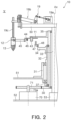
- FIG. 2 shows a partial cross-sectional view of the bag processing machine in a fifth processing section.
- FIG. 3 shows a partial cross-sectional view of the bag processing machine in a seventh processing section.
- FIG. 4 is a plan view showing a bag processing machine (in particular, fourth through ninth processing sections) according to a first modification example.
- FIG. 1 is an oblique perspective view showing a schematic configuration of an example of a bag processing machine 10 .
- FIG. 1 only a part of the bag processing machine 10 is shown, and for example, the illustration of devices that are installed higher than a rotary table 11 are omitted. An example of devices provided above the rotary table 11 is described below with reference to FIGS. 2 and 3 .
- the bag processing machine 10 comprises: a rotary table 11 which rotates intermittently around a central axis; and a plurality of holding units 12 (i.e., pairs of grippers provided on the left and right sides) attached to the outer periphery portion of the rotary table 11 at equal intervals (i.e., equiangular).
- the rotary table 11 repeatedly rotates and stops at predetermined angles. With the intermittent rotation of the rotary table 11 , the holding units 12 move intermittently along a circular travel path. During one rotation of a holding unit 12 , various packaging process are performed, such as supply of a bag 13 to the holding unit 12 (i.e., a bag feeding), opening the mouth portion of the bag 13 , and feeding of contents into the bag 13 , and sealing of the bag 13 .
- the travel path of the holding units 12 is also the path of transfer path of bags 13 .
- a drive source which intermittently rotates the rotary table 11 is omitted.
- a bag feeding step is performed.
- a conveyor magazine type of bag feeding device 14 which supplies bags 13 to the holding units 12 is arranged.
- a bag 13 supplied from the bag feeding device 14 is held at both side edge portions near the mouth portion by a pair of grippers of a holding unit 12 and is suspended in a state where the mouth portion faces upward.
- a printing step is performed.
- a printing device 15 which prints information, such as a date, on the bag surface (i.e., on one sidewall surface) of a bag 13 being suspended by a holding unit 12 , is arranged.
- a third processing section III an opening step in which the mouth portion of a bag 13 is opened, is performed.
- an opening device 16 and an opening guide 17 are arranged, the opening device 16 comprises a pair of suction cups which are able to move closer to each other and further away from each other, and the opening guide 17 supports the mouth portion of a bag 13 from the inside to keep the mouth portion in an open state.
- a solid content feeding step in which a content (i.e., a solid content) is fed into the inside of a bag 13 , is performed.
- a solid content feeding device 18 having a hopper which lifts and lowers is located. The content supplied from a solid content supply part (not shown in the drawings) is guided by the hopper and is fed into the inside of a bag 13 through the mouth portion.
- the opening guide 17 is inserted into the mouth portion in the third processing section III, moves to the fourth processing section IV along with the rotation of the rotary table 11 (i.e., the movement of a holding unit 12 and a bag 13 ) while keeping the mouth portion in an open state, rises to move to the outside of the bag 13 after the solid content feeding device 18 (i.e., the hopper) is inserted into the mouth portion of the bag 13 in the fourth processing section IV, and after that, returns to the third processing section III.
- the solid content feeding device 18 i.e., the hopper
- a liquid injection step in which a content (i.e., a liquid content) is injected into the inside of a bag 13 is performed.
- a liquid injection device 19 having a liquid injection nozzle which lifts and lowers is arranged.
- the content supplied from a liquid supply part e.g., a liquid storage tank; not shown in the drawings
- a liquid supply part e.g., a liquid storage tank; not shown in the drawings
- a gas replacement step in which a gas (for example, steam such as water vapor or an inert gas such as nitrogen) is blown into the inside of a bag 13 , is performed.
- a gas blowing device 20 having a gas blowing nozzle which lifts and lowers is arranged. Gas supplied from a gas supply part (not shown in the drawings) is blown from the gas blowing nozzle to be injected into the inside of a bag 13 .
- the distance between the grippers of a holding unit 12 is increased to tighten the mouth portion of a bag 13 so as to reduce the opening area of the mouth portion.
- a first sealing step to seal a bag 13 is performed.
- a first sealing device 21 having a first sealing heat unit e.g., a pair of heating plates which opens and closes, is arranged.
- a second sealing step to seal a bag 13 is performed.
- a second sealing device 22 having a second sealing heat unit e.g., a pair of heating plates which opens and closes, is arranged.
- a seal part cooling step to cool a bag 13 (in particular, a seal part) and a product bag discharge step to discharge the bag 13 in which the contents are encapsulated therein (i.e., a product bag), are performed.
- a cooling device 23 having a cooling unit that opens and closes, and a bag discharge guide 24 are arranged.
- a bag 13 i.e., a product bag
- a downstream device for example, to a conveyor device such as a belt conveyor not shown in the drawings.
- a bag 13 supported by each holding unit 12 is intermittently stopped at the above-described first processing section I to the ninth processing section IX in accordance with the intermittent rotation of the rotary table 11 and undergo processes sequentially.
- Various devices comprised in the bag processing machine 10 may be driven under the control of a control device (not shown in the drawings) or may be driven independently without being controlled by a control device. Two or more devices driven under the control of a control device may be driven to cooperate with each other by the control device adjusting the driving timing of the devices.
- FIG. 2 shows a partial cross-sectional view of the bag processing machine 10 in the fifth processing section V.
- FIG. 3 shows a partial cross-sectional view of the bag processing machine 10 in the seventh processing section VII.
- a cylindrical stand 31 is fixedly attached to a first supporting base 51 , and a rotary support shaft member 35 is provided inside the stand 31 via a hollow shaft 32 so as to rotate freely.
- the hollow shaft 32 is supported by the inside of the stand 31 via bearings so as to rotate freely
- the rotary support shaft member 35 is supported by the inside of the hollow shaft 32 via bearings so as to rotate freely.
- a drive gear 30 is fixed to the lower end of the rotary support shaft member 35 .
- the drive gear 30 is coupled to a drive source (not show in the drawings), such as a motor, installed between a first supporting base 51 and a second supporting base 52 and rotates intermittently.
- the rotary support shaft member 35 rotates, integrally with the drive gear 30 , in an intermittent manner.
- the hollow shaft 32 and the rotary support shaft member 35 rotate independently of each other around the common rotation center axis Ax.
- the drive gear 30 shown in FIG. 2 is coupled, via a transfer gear 71 , to the output rotation shaft 70 a of the drive source 70 (e.g., a servomotor) attached to the upper surface of the second supporting base 52 .
- the transfer gear 71 rotates integrally with the output rotation shaft 70 a of the drive source 70 , and the rotative power generated by the drive source 70 is transmitted from the output rotation shaft 70 a to the drive gear 30 engaging with the transfer gear 71 , so that the drive gear 30 is rotated.
- the rotary support shaft member 35 (for example, the lower end part of the rotary support shaft member 35 ) is coupled to the drive source 70 provided between the first supporting base 51 , which rotatably supports the rotary support shaft member 35 , and the second supporting base 52 , which supports fixation support shaft member 33 , and consequently the rotary table 11 is rotated along with the rotary support shaft member 35 .
- the first supporting base 51 and the second supporting base 52 are arranged in positions lower than the rotary table 11 , and in particular, the second supporting base 52 is arranged in a position lower than the first supporting base 51 .
- the drive source 70 is supported by the second supporting base 52 in the example shown in FIG.
- the drive source 70 is arranged in such a manner that at least part of (preferably, the entire of) the drive source 70 overlaps, in terms of the height direction (in other words, in a planar view), with at least one of the rotary table 11 and the fixation support member 50 described below.
- the second supporting base 52 is located below and away from the first supporting base 51 .
- drive sources (not shown in the drawings) causing a lever 37 , a rod 38 and the drive gear 30 to rotate, are installed.
- An all-around cam 34 is attached to the upper end portion of the hollow shaft 32 .
- the all-around cam 34 is provided so as to freely slide on the hollow shaft 32 in the upward-downward direction and engages with the hollow shaft 32 in the rotation direction to rotate around the rotation center axis Ax together with the hollow shaft 32 .
- the all-around cam 34 has a substantially disked-shape portion and a cylindrical portion extending upward from the outer periphery portion of the disk-shaped portion, and the upper surface of the cylindrical portion acts as a cam surface.
- the all-around cam 34 can be raised and lowered by a lifting device, not shown in the drawings, to determine its position in the height direction (i.e., the upward-downward direction).
- the lever 37 is fixed to the lower end of the hollow shaft 32 .
- the leading end of the rod 38 which is advanced and retracted by a cam not shown in the drawings, is coupled to the lever 37 so as to rotate freely.
- the hollow shaft 32 and the all-around cam 34 rotate, together with the lever 37 , in the forward direction and in the reverse direction around the rotation center axis Ax.
- the rotary table 11 is attached to the upper end portion of the rotary support shaft member 35 , so that the rotary table 11 is supported by the rotary support shaft member 35 .
- the rotary table 11 is provided so as to freely slide on the rotary support shaft member 35 in a predetermined extent in an axial direction along the rotation center axis Ax, and engages with the rotary support shaft member 35 in a rotation direction around the rotation center axis Ax so as to rotate around the rotation center axis Ax together with the rotary support shaft member 35 .
- the rotary support shaft member 35 rotates intermittently about the rotation center axis Ax, so that the rotary table 11 is caused to intermittently rotate about the rotation center axis Ax.
- each of the holding units 12 includes: a pair of swing levers 44 provided on the left and right sides (in FIGS. 2 and 3 , only a swing lever on one side is shown) attached to a support shaft 43 , fixed to the rotary table 11 , so as to freely rotate; cylindrical gripper arms 45 fixed to the leading ends of the respective swing levers 44 ; and gripping parts attached to the leading ends of the respective gripper arms 45 .
- An air cylinder is arranged inside each gripper arm 45 as a drive source for opening and closing a corresponding gripping part.
- Two swing levers 44 included in each of the gripper pairs are inwardly urged by an extension spring 46 to receive elastic force, from the extension spring 46 , in a direction closer to each other.
- a rolling element 48 is placed on the cam surface of the all-around cam 34 and the rolling element 48 is supported by an L-shaped lever 47 so as to freely rotate.
- the rolling element 48 rolls on the cam surface of the all-around cam 34 .
- the L-shaped lever 47 and the rolling element 48 are a part of a mechanism which causes the two swing levers 44 (and thus the two gripper arms 45 and two gripping parts) to open and close, and this mechanism has the same configuration and the same function as a mechanism described in Japanese examined utility model application publication No. 5-28169 and is attached to the rotary table 11 with respect to each of the holding units 12 .
- a rolling element 48 rolls on the cam surface of the all-around cam 34 .
- the L-shaped lever 47 oscillates to cause the two swing levers 44 (and thus the two gripper arms 45 and the two gripping parts) to open and close in a horizontal plane so as to change the distance between the two gripping parts.
- the all-around cam 34 When the rotary table 11 rotates intermittently, the all-around cam 34 also follows the rotary table 11 to rotate in a forward direction by the same angle as the rotary table 11 , and consequently the relative rotation angle between the rotary table 11 and the all-around cam 34 is zero (0) and no substantial relative rotation occurs between the rotary table 11 and the all-around cam 34 .
- the all-around cam 34 rotates in the opposite direction to return to its original position, and consequently a substantial relative rotation occurs between the rotary table 11 and the all-around cam 34 .
- the bag processing machine 10 is the same as a packaging machine described in Japanese examined utility model application publication No. 5-28169.
- an air cylinder is used for a drive source to perform opening and closing of a gripping part of each holding unit 12 , and this air cylinder is located inside a gripper arm 45 .
- the opening and closing of a gripper part of a holding unit 12 may be performed by an opening-closing drive mechanism installed in a proper place (for example, a position for a step of supplying an empty bag or a position for a step of discharging a filled bag) on the first supporting base 51 or on the second supporting base 52 .
- a gripper described in Japanese patent application publication No. 6-156440 includes: a pair of swing levers provided on the left and right sides attached to a table which rotates intermittently; gripper arms having base portions fixed to the respective swing levers; and gripping parts arranged on the leading ends of respective gripper arms to inwardly face each other, and each of the gripping parts includes: a fixed side gripping piece having a gripping surface directed in a radiation direction; and a movable side gripping piece attached to the leading end of a gripper arm so as to freely rotate.
- This gripper is similar to the gripper described in Japanese patent application publication No. 2009-298418.
- connection mechanism part On a gripper arm, a connection mechanism part and a compressed spring are installed, the connection mechanism part transmits the power of the opening-closing drive mechanism to the movable side gripping piece, and the compressed spring is installed in the gripper arm to constantly urge the movable side gripping piece in a closing direction.
- a cylindrical member i.e., a roller
- the movable side gripping piece opens, and when the projecting member moves backward, the movable side gripping piece is closed under the urging force of the compressed spring.
- the bag processing machine 10 of the present embodiment further comprises: a fixation support shaft member 33 which is fixedly attached to the second supporting base 52 via a support fixation member 53 ; and a fixation support member 50 which is fixedly attached to the fixation support shaft member 33 .
- the fixation support shaft member 33 extends in the height direction so as to penetrate the inside of the rotary support shaft member 35 and is located on the rotation center axis Ax. Bearings are provided between the rotary support shaft member 35 and the fixation support shaft member 33 . The rotation of the rotary support shaft member 35 (and thus the rotary table 11 ) about the rotation center axis Ax does not rotate the fixation support shaft member 33 .
- the disk-shaped fixation support member 50 supported by the fixation support shaft member 33 is attached to the top of the fixation support shaft member 33 to be positioned above the rotary table 11 and the plurality of holding units 12 . Since the rotation of the rotary support shaft member 35 supporting the rotary table 11 does not rotate the fixation support shaft member 33 supporting the fixation support member 50 as described above, the rotation of the rotary table 11 does not rotate the fixation support member 50 .
- two or more processing devices which perform processes on bags 13 held by the plurality of holding units 12 in two or more processing sections respectively of the plurality of processing sections (i.e., the first processing section I to the ninth processing section IX) are supported by the fixation support member 50 .
- the processing devices here may include the bag feeding device 14 , the printing device 15 , the opening device 16 , the opening guide 17 , the solid content feeding device 18 , the liquid injection device 19 , the gas blowing device 20 , the first sealing device 21 , the second sealing device 22 , and the cooling device 23 .
- the liquid injection device 19 is supported by the fixation support member 50 .
- the liquid injection device 19 shown in FIG. 2 comprises: a liquid injection drive source 19 a ; a liquid injection nozzle 19 c ; and a liquid injection movement mechanism 19 b which are connected to the liquid injection drive source 19 a and the liquid injection nozzle 19 c .
- the power output from the liquid injection drive source 19 a is transmitted to the liquid injection movement mechanism 19 b .
- the liquid injection movement mechanism 19 b operates in response to the power transmitted from the liquid injection drive source 19 a to move the liquid injection nozzle 19 c upward and downward in the height direction.
- the specific configurations of the liquid injection drive source 19 a , the liquid injection movement mechanism 19 b and the liquid injection nozzle 19 c are not limited, and the liquid injection device 19 can be configured by a known device.
- the liquid injection drive source 19 a may be configured by a motor or the like; and the liquid injection movement mechanism 19 b may be configured by a mechanism (for example, a mechanism which includes a link mechanism at least in part) which converts the power transmitted from the liquid injection drive source 19 a into power acting in the upward-downward direction.
- the liquid injection nozzle 19 c can be moved upward and downward in the height direction by the power acting in the upward-downward direction transmitted from the liquid injection movement mechanism 19 b.
- the liquid injection drive source 19 a and a part of the liquid injection movement mechanism 19 b are positioned directly above the fixation support member 50 and are fixedly attached to the fixation support member 50 (in particular, to the top surface).
- the first sealing device 21 is supported by the fixation support member 50 .
- the first sealing device 21 shown in FIG. 3 comprises: a first sealing drive source 21 a ; a first sealing heat unit 21 c ; and a first sealing movement mechanism 21 b which are connected to the first sealing drive source 21 a and the first sealing heat unit 21 c .
- the power output from the first sealing drive source 21 a is transmitted to the first sealing movement mechanism 21 b .
- the first sealing movement mechanism 21 b operates in response to the power transmitted from the first sealing drive source 21 a to cause the first sealing heat unit 21 c to perform an opening action and a closing action in a horizontal direction (in particular, in the direction of the thickness of a bag 13 held by a holding unit 12 ).
- the first sealing heat unit 21 c heats and pressurizes the mouth portion of a bag 13 while pinching the mouth portion, to perform heat sealing on the mouth portion in such a manner that the inside of the bag 13 is sealed off.
- the specific configurations of the first sealing drive source 21 a , the first sealing movement mechanism 21 b and the first sealing heat unit 21 c are not limited, and the first sealing device 21 can be configured by a known device.
- the first sealing drive source 21 a may be configured by a motor or the like; and the first sealing movement mechanism 21 b may be configured by a mechanism (for example, a mechanism which includes a link mechanism at least in part) which converts the power transmitted from the first sealing drive source 21 a into power acting in a horizontal direction.
- the first sealing heat unit 21 c can be caused to perform an opening action and a closing action in a horizontal direction by the power acting in a horizontal direction which is transmitted from the first sealing movement mechanism 21 b.
- the first sealing drive source 21 a and a part of the first sealing movement mechanism 21 b are positioned directly above the fixation support member 50 and are fixedly attached to the fixation support member 50 (in particular, to the top surface).
- processing devices which perform processes on an upper part of each bag 13 are at least partially positioned directly above the fixation support member 50 and are fixedly attached to the fixation support member 50 (in particular, to the top surface).
- processing devices which perform processes on parts other than the upper part of each bag 13 are fixedly attached to the first supporting base 51 (in particular, to the top surface).
- the printing device 15 and the opening device 16 are supported by the first supporting base 51 .
- the opening guide 17 , the solid content feeding device 18 , the liquid injection device 19 , the gas blowing device 20 , the first sealing device 21 , the second sealing device 22 , and the cooling device 23 are at least partially supported by the fixation support member 50 (in particular, by the top surface).
- processing devices for example, the liquid injection device 19 (see FIG. 2 ) and the first sealing device 21 (see FIG. 3 )
- processing devices are installed on the top surface of the fixation support member 50 , and those processing devices are provided on the opposite side, via the fixation support member 50 , from the rotary table 11 and each holding unit 12 .
- one or more processing devices may be installed on the under surface of the fixation support member 50 , and the one or more processing devices may be positioned between the fixation support member 50 and the rotary table 11 in the height direction.
- a processing device which performs a process on a part of a bag 13 other than the upper part may be supported by the fixation support member 50 .
- a processing device which performs a process on an upper part of a bag 13 may be supported by a member other than the fixation support member 50 (for example, by the first supporting base 51 or the second supporting base 52 ).
- a processing device e.g., a print inspection device not shown in the drawings may be supported by the fixation support member 50 or may be supported by a member other than the fixation support member 50 .
- the bag processing machine 10 of the present embodiment comprises: a rotary table 11 (a rotation body) which is rotated intermittently; a plurality of holding units 12 which are attached to the rotary table 11 and are moved along a circular movement path in accordance with the rotation of the rotary table 11 , the circular movement path being divided into a plurality of processing sections I to IX; a fixation support member 50 which is positioned above the rotary table 11 and does not rotate by the rotation of the rotary table 11 ; and two or more processing devices which are supported by the fixation support member 50 and perform processes on bags 13 held by the plurality of holding units 12 in two or more processing sections respectively of the plurality of processing sections I to IX.
- this bag processing machine 10 two or more processing devices are supported by the fixation support member 50 .
- This allows the space above the rotary table 11 to be effectively utilized to install two or more processing devices.
- it is advantageous to reduce the planar size of the area for the installation of a plurality of processing devices which the bag processing machine 10 comprises.
- processing devices on the top surface of the fixation support member 50 , it is possible to effectively reduce the contamination of said processing devices by the contents (i.e., solids and liquids) during operation of the bag processing machine 10 .
- processing devices on the under surface of the fixation support member 50 the distance between the processing devices and bags 13 are shortened and obstructions between the processing devices and bags 13 are also reduced, which may promote simplification and downsizing of processing devices.
- the bag processing machine 10 of the present embodiment comprises: a rotary support shaft member 35 which supports the rotary table 11 ; and a fixation support shaft member 33 which extends inside the rotary support shaft member 35 and supports the fixation support member 50 .
- FIG. 4 is a plan view of a bag processing machine 10 (in particular, the fourth processing section IV through the ninth processing section IX) according to a first modification example.
- the bag processing machine 10 according to the present modification example has basically the same configuration as the bag processing machine 10 shown in FIGS. 1 to 3 described above. However, in the present modification example, while the rotary table 11 is stopped intermittently, two or more holding units 12 (specifically, four holding units 12 ) are arranged in each of the plurality of processing sections I-IX.
- movable processing units of two or more processing devices supported by the fixation support member 50 perform the same process, at the same timing, on two or more bags 13 held by two ore more holding units 12 arranged in corresponding processing sections.
- the solid content feeding device 18 , the liquid injection device 19 , the gas blowing device 20 , the first sealing device 21 , and the cooling device 23 are attached to the top surface of the fixation support member 50 and are supported by the fixation support member 50 .
- the solid content feeding device 18 comprises: a single solid content feeding drive source 18 a ; a plurality (specifically, four) of solid content feeding guides (e.g., hoppers) 18 c ; and a single solid content feeding movement mechanism 18 b which is connected to the solid content feeding drive source 18 a and each solid content feeding guide 18 c .
- the power output from the solid content feeding drive source 18 a is transmitted to the solid content feeding movement mechanism 18 b .
- the solid content feeding movement mechanism 18 b operates in response to the power transmitted from the solid content feeding drive source 18 a to move the four solid content feeding guides 18 c upward and downward in the height direction.
- the solid content feeding device 18 includes: the four solid content feeding guides 18 c (i.e., movable processing units) which are provided to be able to move with respect to four bags 13 held by four holding units 12 arranged in the corresponding processing section (i.e., in the fourth processing section IV); and the solid content feeding movement mechanism 18 b which causes the four solid content feeding guides 18 c to move.
- the four solid content feeding guides 18 c i.e., movable processing units
- the solid content feeding movement mechanism 18 b which causes the four solid content feeding guides 18 c to move.
- the liquid injection device 19 includes: a single liquid injection drive source 19 a ; a plurality (specifically, four) of liquid injection nozzles 19 c ; a single liquid injection movement mechanism 19 b which are connected to the liquid injection drive source 19 a and each liquid injection nozzle 19 c .
- the power output from the liquid injection drive source 19 a is transmitted to the liquid injection movement mechanism 19 b .
- the liquid injection movement mechanism 19 b operates in response to the power transmitted from the liquid injection drive source 19 a to move the four liquid injection nozzles 19 c upward and downward in the height direction.
- the gas blowing device 20 includes: a single gas blowing drive source 20 a ; a plurality (specifically, four) of gas blowing nozzles 20 c ; and a single gas blowing movement mechanism 20 b which is connected to the gas blowing drive source 20 a and each gas blowing nozzle 20 c .
- the power output from the gas blowing drive source 20 a is transmitted to the gas blowing movement mechanism 20 b .
- the gas blowing movement mechanism 20 b operates in response to the power transmitted from the gas blowing drive source 20 a to move the four gas blowing nozzles 20 c upward and downward in the height direction.
- the first sealing device 21 includes: a plurality (specifically, two) of first sealing drive sources 21 a ; a plurality (specifically, four) of first sealing heat units 21 c ; and a plurality (specifically, two) of first sealing movement mechanisms 21 b .
- One first sealing drive source 21 a and a plurality (specifically, two) of first sealing heat units 21 c are connected to each of the first sealing movement mechanisms 21 b .
- each first sealing drive source 21 a The power output from each first sealing drive source 21 a is transmitted to a corresponding first sealing movement mechanism 21 b , the first sealing movement mechanism 21 b operates in response to the power transmitted from the first sealing drive source 21 a to cause two corresponding first sealing heat units 21 c to perform an opening action and a closing action in a horizontal direction.
- the first sealing device 21 performs the same process, at the same timing, on two bags 13 held by two holding units arranged in the corresponding seventh processing section VII.
- the two first sealing drive sources 21 a are driven in synchronization with each other and the two first sealing movement mechanisms 21 b are driven in synchronization with each other, it is possible to perform the same process, at the same timing, on four bags 13 held by four holding units 12 arranged in the seventh processing section VII.
- the second sealing device 22 includes: a plurality (specifically, two) of second sealing drive sources 22 a ; a plurality (specifically, four) of second sealing heat units 22 c ; and a plurality (specifically, two) of second sealing movement mechanisms 22 b .
- One second sealing drive source 22 a and a plurality (specifically, two) of second sealing heat units 22 c are connected to each second sealing movement mechanism 22 b .
- the power output from each second sealing drive source 22 a is transmitted to a corresponding second sealing movement mechanism 22 b
- the second sealing movement mechanism 22 b operates in response to the power transmitted from the second sealing drive source 22 a to cause two corresponding second sealing heat units 22 c to perform an opening action and a closing action in a horizontal direction.
- the cooling device 23 includes: a plurality (specifically, two) of cooling drive sources 23 a ; a plurality (specifically, four) of cooling units 23 c ; and a plurality (specifically, two) of cooling movement mechanisms 23 b .
- One cooling drive source 23 a and a plurality (specifically, two) of cooling units 23 c are connected to each cooling movement mechanism 23 b .
- the power output from each cooling drive source 23 a is transmitted to a corresponding cooling movement mechanism 23 b
- the cooling movement mechanism 23 b operates in response to the power transmitted from the cooling drive source 23 a to cause two corresponding cooling units 23 c to perform an opening action and a closing action in a horizontal direction.
- At least one of the two or more processing devices includes: a movable processing unit which is provided to be able to move with respect to two or more bags 13 held by two or more holding units 12 positioned in a correspond processing section; and a movement drive unit which moves the movable processing unit, and the movable processing unit performs a same process on two ore more bags 13 held by two or more holding units 12 positioned in a correspond processing section.
- a movable processing unit can be moved between a position for performing a process on a corresponding bag 13 and a position for evacuating from the corresponding bag 13 by simply moving the movable processing unit of a processing device upward and downward in the height direction (see the solid content feeding device 18 , the liquid injection device 19 , and the gas blowing device 20 shown in FIG. 4 ), it is possible to move many movable processing units at one time by a single drive source and a single movement mechanism.
Landscapes
- Engineering & Computer Science (AREA)
- Mechanical Engineering (AREA)
- Chemical & Material Sciences (AREA)
- Dispersion Chemistry (AREA)
- Supplying Of Containers To The Packaging Station (AREA)
- Package Closures (AREA)
Abstract
Description
Claims (6)
Applications Claiming Priority (2)
| Application Number | Priority Date | Filing Date | Title |
|---|---|---|---|
| JP2021-075314 | 2021-04-27 | ||
| JP2021075314A JP2022169338A (en) | 2021-04-27 | 2021-04-27 | bag processing machine |
Publications (2)
| Publication Number | Publication Date |
|---|---|
| US20220340320A1 US20220340320A1 (en) | 2022-10-27 |
| US12012245B2 true US12012245B2 (en) | 2024-06-18 |
Family
ID=81388975
Family Applications (1)
| Application Number | Title | Priority Date | Filing Date |
|---|---|---|---|
| US17/724,023 Active US12012245B2 (en) | 2021-04-27 | 2022-04-19 | Bag processing machine |
Country Status (3)
| Country | Link |
|---|---|
| US (1) | US12012245B2 (en) |
| EP (1) | EP4086181A1 (en) |
| JP (2) | JP2022169338A (en) |
Cited By (1)
| Publication number | Priority date | Publication date | Assignee | Title |
|---|---|---|---|---|
| US20240174398A1 (en) * | 2022-11-25 | 2024-05-30 | PACRAFT Co., Ltd. | Packaging method and packaging apparatus |
Families Citing this family (5)
| Publication number | Priority date | Publication date | Assignee | Title |
|---|---|---|---|---|
| US10335149B2 (en) * | 2015-06-18 | 2019-07-02 | Ethicon Llc | Articulatable surgical instruments with composite firing beam structures with center firing support member for articulation support |
| JP7448141B2 (en) * | 2020-03-30 | 2024-03-12 | ゼネラルパッカー株式会社 | Packaging machine with bottom receiving device |
| CN115610764B (en) * | 2022-12-05 | 2023-05-09 | 河北大安制药有限公司 | Blood bag transferring and packaging machine |
| WO2025050714A1 (en) * | 2023-09-07 | 2025-03-13 | 成都市珑熙科技有限公司 | Packaging device and retractable packaging machine |
| CN119408808A (en) * | 2025-01-07 | 2025-02-11 | 四川立顿洗涤用品有限公司 | Washing article packaging device |
Citations (16)
| Publication number | Priority date | Publication date | Assignee | Title |
|---|---|---|---|---|
| US3893600A (en) * | 1974-04-24 | 1975-07-08 | Walter A Shields | Liquid gravity feed system |
| JPS6130546B2 (en) * | 1977-12-29 | 1986-07-14 | Nippon Oxygen Co Ltd | |
| JPH0528169Y2 (en) | 1987-02-21 | 1993-07-20 | ||
| JPH06156440A (en) | 1992-02-29 | 1994-06-03 | Toyo Jidoki Co Ltd | Bag-holding device in automatic packing machine |
| US5845466A (en) * | 1996-11-15 | 1998-12-08 | Laudenberg; Bernd | Multiple package machine |
| US6199601B1 (en) * | 1998-02-17 | 2001-03-13 | Profile Packaging, Inc. | Method and apparatus for filling flexible pouches |
| US6244307B1 (en) | 1998-04-30 | 2001-06-12 | Mitsubishi Heavy Industries, Ltd. | Transportation, feeding and filling apparatus of irregular-formed vessels and transportation and feeding method |
| JP2005008256A (en) * | 2003-06-20 | 2005-01-13 | Shibuya Kogyo Co Ltd | Manufacturing apparatus for bag-like container |
| EP1247767B1 (en) | 2001-04-04 | 2005-12-07 | Toyo Jidoki Co., Ltd. | A bag conveying apparatus and a gripper endless chain used in a bag filling packaging machine |
| CN1743233A (en) * | 2005-08-29 | 2006-03-08 | 湖南千山制药机械股份有限公司 | Intermittent rotary solid-drug-chargeable non-PVC infusion bag solid-drug filling machine |
| EP1770018A1 (en) | 2005-10-03 | 2007-04-04 | Toyo Jidoki Co., Ltd. | Bag-filling packaging machine |
| US20090308031A1 (en) | 2008-06-11 | 2009-12-17 | Toyo Jidoki Co., Ltd. | Gripper for an automatic bag filling apparatus |
| JP2011240962A (en) | 2010-05-18 | 2011-12-01 | Toyo Jidoki Co Ltd | Intermittent-turntable-type bagging machine |
| US8684048B2 (en) * | 2010-02-26 | 2014-04-01 | Toyo Jidoki Co., Ltd. | Standalone packaging manipulation apparatus |
| US9096333B2 (en) * | 2011-11-17 | 2015-08-04 | Toyo Jidoki Co., Ltd. | Rotary-type bag filling and packaging machine |
| US20190062086A1 (en) | 2017-08-25 | 2019-02-28 | Toyo Jidoki Co., Ltd. | Conveyance mechanism |
Family Cites Families (7)
| Publication number | Priority date | Publication date | Assignee | Title |
|---|---|---|---|---|
| JPS61127403A (en) * | 1984-11-27 | 1986-06-14 | 四国化工機株式会社 | Packaging machine |
| JPH0312645Y2 (en) * | 1987-09-07 | 1991-03-25 | ||
| JPH0528169U (en) | 1991-09-17 | 1993-04-09 | 村田機械株式会社 | Facsimile device with operation status aggregation function |
| JP2001088810A (en) * | 1999-09-20 | 2001-04-03 | Shinsei:Kk | Packaging bag lateral move preventive device of continuous high speed filling and packaging machine |
| US9505504B2 (en) * | 2011-02-18 | 2016-11-29 | Pouch Pac Innovations, Llc | Apparatus for the two stage filling of flexible pouches |
| JP6228802B2 (en) * | 2013-10-07 | 2017-11-08 | 花王株式会社 | Bag-shaped container filling apparatus, bag-shaped container filling method, and bag-shaped package manufacturing method |
| CN208248612U (en) * | 2018-05-30 | 2018-12-18 | 郑州元兴科技有限公司 | It is a kind of for sealing the rotary sealing machine of three edge sealing bags |
-
2021
- 2021-04-27 JP JP2021075314A patent/JP2022169338A/en active Pending
-
2022
- 2022-04-19 US US17/724,023 patent/US12012245B2/en active Active
- 2022-04-27 EP EP22170282.2A patent/EP4086181A1/en active Pending
-
2025
- 2025-04-07 JP JP2025063025A patent/JP2025096409A/en active Pending
Patent Citations (17)
| Publication number | Priority date | Publication date | Assignee | Title |
|---|---|---|---|---|
| US3893600A (en) * | 1974-04-24 | 1975-07-08 | Walter A Shields | Liquid gravity feed system |
| JPS6130546B2 (en) * | 1977-12-29 | 1986-07-14 | Nippon Oxygen Co Ltd | |
| JPH0528169Y2 (en) | 1987-02-21 | 1993-07-20 | ||
| JPH06156440A (en) | 1992-02-29 | 1994-06-03 | Toyo Jidoki Co Ltd | Bag-holding device in automatic packing machine |
| US5845466A (en) * | 1996-11-15 | 1998-12-08 | Laudenberg; Bernd | Multiple package machine |
| US6199601B1 (en) * | 1998-02-17 | 2001-03-13 | Profile Packaging, Inc. | Method and apparatus for filling flexible pouches |
| US6244307B1 (en) | 1998-04-30 | 2001-06-12 | Mitsubishi Heavy Industries, Ltd. | Transportation, feeding and filling apparatus of irregular-formed vessels and transportation and feeding method |
| EP1247767B1 (en) | 2001-04-04 | 2005-12-07 | Toyo Jidoki Co., Ltd. | A bag conveying apparatus and a gripper endless chain used in a bag filling packaging machine |
| JP2005008256A (en) * | 2003-06-20 | 2005-01-13 | Shibuya Kogyo Co Ltd | Manufacturing apparatus for bag-like container |
| CN1743233A (en) * | 2005-08-29 | 2006-03-08 | 湖南千山制药机械股份有限公司 | Intermittent rotary solid-drug-chargeable non-PVC infusion bag solid-drug filling machine |
| EP1770018A1 (en) | 2005-10-03 | 2007-04-04 | Toyo Jidoki Co., Ltd. | Bag-filling packaging machine |
| US20090308031A1 (en) | 2008-06-11 | 2009-12-17 | Toyo Jidoki Co., Ltd. | Gripper for an automatic bag filling apparatus |
| JP2009298418A (en) | 2008-06-11 | 2009-12-24 | Toyo Jidoki Co Ltd | Gripper for automatic filling machine |
| US8684048B2 (en) * | 2010-02-26 | 2014-04-01 | Toyo Jidoki Co., Ltd. | Standalone packaging manipulation apparatus |
| JP2011240962A (en) | 2010-05-18 | 2011-12-01 | Toyo Jidoki Co Ltd | Intermittent-turntable-type bagging machine |
| US9096333B2 (en) * | 2011-11-17 | 2015-08-04 | Toyo Jidoki Co., Ltd. | Rotary-type bag filling and packaging machine |
| US20190062086A1 (en) | 2017-08-25 | 2019-02-28 | Toyo Jidoki Co., Ltd. | Conveyance mechanism |
Non-Patent Citations (1)
| Title |
|---|
| Extended European Search Report dated Oct. 10, 2022, issued in corresponding European Patent Application No. 22170282.2 (8 pgs.). |
Cited By (1)
| Publication number | Priority date | Publication date | Assignee | Title |
|---|---|---|---|---|
| US20240174398A1 (en) * | 2022-11-25 | 2024-05-30 | PACRAFT Co., Ltd. | Packaging method and packaging apparatus |
Also Published As
| Publication number | Publication date |
|---|---|
| JP2022169338A (en) | 2022-11-09 |
| US20220340320A1 (en) | 2022-10-27 |
| EP4086181A1 (en) | 2022-11-09 |
| JP2025096409A (en) | 2025-06-26 |
Similar Documents
| Publication | Publication Date | Title |
|---|---|---|
| US12012245B2 (en) | Bag processing machine | |
| KR101641881B1 (en) | Packaging processing device for packaging machine | |
| KR101912464B1 (en) | Product packaging apparatus | |
| KR102061432B1 (en) | Vacuum packing machine | |
| US9650165B2 (en) | Tray sealer | |
| CN101691141B (en) | Aluminum box packing machine | |
| JP2011240962A (en) | Intermittent-turntable-type bagging machine | |
| US11505341B1 (en) | Robotic case packer platform and packing method | |
| JP5597927B2 (en) | Workpiece transfer device | |
| CN114803005B (en) | Automatic packaging equipment for strip-shaped workpieces | |
| CN101132967A (en) | Packaging machine for automated packaging of products into cardboard boxes | |
| KR20180068858A (en) | Container transporting apparatus | |
| US11046470B2 (en) | Packaging system | |
| KR101733282B1 (en) | A rotary type automatic packing apparatus | |
| KR20200074016A (en) | Gas replacement apparatus | |
| CN201484678U (en) | Sealing device of aluminum box packager | |
| KR102042962B1 (en) | Continuous vacuum system | |
| JP2000326917A (en) | Boxing device for bottle | |
| JP4631146B2 (en) | Cleaning device for filling nozzle | |
| KR101819973B1 (en) | Vacuum processor | |
| CN112550830A (en) | Bag feeding and packaging machine | |
| CN217533539U (en) | Inner and outer bag integrated machine | |
| CN114802994B (en) | An integrated internal and external packaging machine | |
| JP2020059161A (en) | Joint device and spout seal machine | |
| CN101633413B (en) | Sealing device of aluminum box packaging machine |
Legal Events
| Date | Code | Title | Description |
|---|---|---|---|
| FEPP | Fee payment procedure |
Free format text: ENTITY STATUS SET TO UNDISCOUNTED (ORIGINAL EVENT CODE: BIG.); ENTITY STATUS OF PATENT OWNER: LARGE ENTITY |
|
| STPP | Information on status: patent application and granting procedure in general |
Free format text: DOCKETED NEW CASE - READY FOR EXAMINATION |
|
| AS | Assignment |
Owner name: PACRAFT CO., LTD., JAPAN Free format text: ASSIGNMENT OF ASSIGNORS INTEREST;ASSIGNOR:NAKAMOTO, KAKUE;REEL/FRAME:060278/0768 Effective date: 20220614 |
|
| STPP | Information on status: patent application and granting procedure in general |
Free format text: NON FINAL ACTION MAILED |
|
| STPP | Information on status: patent application and granting procedure in general |
Free format text: RESPONSE TO NON-FINAL OFFICE ACTION ENTERED AND FORWARDED TO EXAMINER |
|
| STPP | Information on status: patent application and granting procedure in general |
Free format text: FINAL REJECTION MAILED |
|
| STCV | Information on status: appeal procedure |
Free format text: NOTICE OF APPEAL FILED |
|
| STPP | Information on status: patent application and granting procedure in general |
Free format text: DOCKETED NEW CASE - READY FOR EXAMINATION |
|
| STPP | Information on status: patent application and granting procedure in general |
Free format text: NOTICE OF ALLOWANCE MAILED -- APPLICATION RECEIVED IN OFFICE OF PUBLICATIONS |
|
| STPP | Information on status: patent application and granting procedure in general |
Free format text: PUBLICATIONS -- ISSUE FEE PAYMENT RECEIVED |
|
| STPP | Information on status: patent application and granting procedure in general |
Free format text: PUBLICATIONS -- ISSUE FEE PAYMENT VERIFIED |
|
| STCF | Information on status: patent grant |
Free format text: PATENTED CASE |