US12011306B2 - Patient head protection device - Google Patents
Patient head protection device Download PDFInfo
- Publication number
- US12011306B2 US12011306B2 US16/731,548 US201916731548A US12011306B2 US 12011306 B2 US12011306 B2 US 12011306B2 US 201916731548 A US201916731548 A US 201916731548A US 12011306 B2 US12011306 B2 US 12011306B2
- Authority
- US
- United States
- Prior art keywords
- shield
- patient
- protection device
- head
- support platform
- Prior art date
- Legal status (The legal status is an assumption and is not a legal conclusion. Google has not performed a legal analysis and makes no representation as to the accuracy of the status listed.)
- Active, expires
Links
Images


Classifications
-
- A—HUMAN NECESSITIES
- A61—MEDICAL OR VETERINARY SCIENCE; HYGIENE
- A61B—DIAGNOSIS; SURGERY; IDENTIFICATION
- A61B6/00—Apparatus or devices for radiation diagnosis; Apparatus or devices for radiation diagnosis combined with radiation therapy equipment
- A61B6/10—Safety means specially adapted therefor
- A61B6/102—Protection against mechanical damage, e.g. anti-collision devices
-
- A—HUMAN NECESSITIES
- A61—MEDICAL OR VETERINARY SCIENCE; HYGIENE
- A61B—DIAGNOSIS; SURGERY; IDENTIFICATION
- A61B6/00—Apparatus or devices for radiation diagnosis; Apparatus or devices for radiation diagnosis combined with radiation therapy equipment
- A61B6/02—Arrangements for diagnosis sequentially in different planes; Stereoscopic radiation diagnosis
- A61B6/03—Computed tomography [CT]
- A61B6/032—Transmission computed tomography [CT]
-
- A—HUMAN NECESSITIES
- A61—MEDICAL OR VETERINARY SCIENCE; HYGIENE
- A61B—DIAGNOSIS; SURGERY; IDENTIFICATION
- A61B6/00—Apparatus or devices for radiation diagnosis; Apparatus or devices for radiation diagnosis combined with radiation therapy equipment
- A61B6/48—Diagnostic techniques
- A61B6/486—Diagnostic techniques involving generating temporal series of image data
- A61B6/487—Diagnostic techniques involving generating temporal series of image data involving fluoroscopy
-
- A—HUMAN NECESSITIES
- A61—MEDICAL OR VETERINARY SCIENCE; HYGIENE
- A61B—DIAGNOSIS; SURGERY; IDENTIFICATION
- A61B6/00—Apparatus or devices for radiation diagnosis; Apparatus or devices for radiation diagnosis combined with radiation therapy equipment
- A61B6/50—Apparatus or devices for radiation diagnosis; Apparatus or devices for radiation diagnosis combined with radiation therapy equipment specially adapted for specific body parts; specially adapted for specific clinical applications
- A61B6/501—Apparatus or devices for radiation diagnosis; Apparatus or devices for radiation diagnosis combined with radiation therapy equipment specially adapted for specific body parts; specially adapted for specific clinical applications for diagnosis of the head, e.g. neuroimaging or craniography
-
- A—HUMAN NECESSITIES
- A61—MEDICAL OR VETERINARY SCIENCE; HYGIENE
- A61B—DIAGNOSIS; SURGERY; IDENTIFICATION
- A61B90/00—Instruments, implements or accessories specially adapted for surgery or diagnosis and not covered by any of the groups A61B1/00 - A61B50/00, e.g. for luxation treatment or for protecting wound edges
- A61B90/03—Automatic limiting or abutting means, e.g. for safety
- A61B2090/033—Abutting means, stops, e.g. abutting on tissue or skin
-
- A—HUMAN NECESSITIES
- A61—MEDICAL OR VETERINARY SCIENCE; HYGIENE
- A61B—DIAGNOSIS; SURGERY; IDENTIFICATION
- A61B6/00—Apparatus or devices for radiation diagnosis; Apparatus or devices for radiation diagnosis combined with radiation therapy equipment
- A61B6/04—Positioning of patients; Tiltable beds or the like
- A61B6/0407—Supports, e.g. tables or beds, for the body or parts of the body
-
- A—HUMAN NECESSITIES
- A61—MEDICAL OR VETERINARY SCIENCE; HYGIENE
- A61B—DIAGNOSIS; SURGERY; IDENTIFICATION
- A61B6/00—Apparatus or devices for radiation diagnosis; Apparatus or devices for radiation diagnosis combined with radiation therapy equipment
- A61B6/10—Safety means specially adapted therefor
- A61B6/107—Protection against radiation, e.g. shielding
-
- A—HUMAN NECESSITIES
- A61—MEDICAL OR VETERINARY SCIENCE; HYGIENE
- A61B—DIAGNOSIS; SURGERY; IDENTIFICATION
- A61B6/00—Apparatus or devices for radiation diagnosis; Apparatus or devices for radiation diagnosis combined with radiation therapy equipment
- A61B6/44—Constructional features of apparatus for radiation diagnosis
- A61B6/4429—Constructional features of apparatus for radiation diagnosis related to the mounting of source units and detector units
- A61B6/4435—Constructional features of apparatus for radiation diagnosis related to the mounting of source units and detector units the source unit and the detector unit being coupled by a rigid structure
- A61B6/4441—Constructional features of apparatus for radiation diagnosis related to the mounting of source units and detector units the source unit and the detector unit being coupled by a rigid structure the rigid structure being a C-arm or U-arm
Definitions
- the present invention relates, in some embodiments thereof, to devices and methods for protecting a patient's upper body portion from collision with medical instruments, such as an X-ray imaging system and/or an X-ray radiation protection apparatus.
- the invention provides a head protection device comprising a support platform for supporting a patient's head; and a head protection shield connected to the support platform.
- the shield is pivotally connected to the support platform to allow a relative pivotal movement between the support platform and the shield.
- the device includes an adjuster unit allowing to vertically adjust the distance between the head protector shield and the support platform, thereby allowing to fit various head sizes.
- 3D and 2D images of a body are obtained using a C-arm rotating around a patient.
- the movement of the C-arm around the patient entails the risk of a collision of the C-arm, in particular of the X-ray detector, with the patient and/or creating a stressful environment for the patient.
- the most critical and hazardous collision event is associated with possible harmful collisions of moving parts of the C-arm with a patient's head, especially in events of unexpected patient movements.
- U.S. Pat. No. 7,857,512 discloses a collision protection device for a patient examination table of a medical X-ray device, comprising: a protective element made of an X-ray transparent/radiolucent material that mechanically shields at least a part of the patient examination table; a feeler; a collision sensor, wherein the collision sensor is arranged in the feeler; and a stand or a base directly connected to the collision protection device that decouples the collision protection device from the patient examination table.
- U.S. Pat. No. 9,038,219 discloses a patient support apparatus having a support table, a transfer plate, which is disposed movably in relation to the support table in a direction and on which a patient is supported for a surgical intervention and/or a medical imaging examination, and a surgical head restraint unit, which is disposed on the transfer plate.
- the patient support apparatus includes a position monitoring apparatus for monitoring and/or checking a position of the surgical head restraint unit.
- the device should include a shield to cover the face and/or neck, a support platform to support the head, and means to move the shield pivotably over the face.
- collision protection devices for assuring simple and reliable avoidance of collisions between moving parts of a medical fluoroscopy X-ray device and a patient.
- Objects of the invention are achieved by providing head protection devices and systems for protecting an upper body portion (i.e., the head or face and optionally the neck) of a patient in the process of X-ray imaging.
- An aspect of the invention pertains to a patient protection shield in accordance with the disclosure herein below.
- An aspect of the invention pertains to a method of shielding a patient in accordance with the disclosure herein below.
- An aspect of the invention pertains to a medical device including a head protection shield in accordance with the disclosure herein above.
- An aspect of the invention pertains to a patient head collision protection device, comprising:
- An aspect of the invention pertains to a patient head protection device, comprising:
- An aspect of the invention pertains to a patient head protection device for protecting an upper body portion of a patient from collision with X-ray equipment, the device comprising:
- An aspect of the invention pertains to a patient head protection device for protecting an upper body portion of a patient from collision with moving parts of X-ray equipment, the device comprising:
- the adjuster unit is configured to adjust the distance of the shield from the patient's head platform or from a patient support platform to fit various head sizes and allow free head movements.
- the device includes attachment means to allow an attachment of the shield and/or a rear/side vertical wall thereof, and/or support platform to a sub-system and/or an add-on system, and/or a patient's head platform (e.g., patient table/bed/chair).
- attachment means to allow an attachment of the shield and/or a rear/side vertical wall thereof, and/or support platform to a sub-system and/or an add-on system, and/or a patient's head platform (e.g., patient table/bed/chair).
- the device includes attachment means to allow an attachment of the shield and/or a vertical wall thereof to a patient's head platform.
- the patient's head platform selected from a patient table, a patient bed, and a patient chair.
- the attachment means allow a permanent fixature. In one or more embodiments, the attachment means allow a temporary fixature.
- the support platform is configured to support a patient's head.
- the support platform is configured to attach a patient's bed/table.
- the support platform is affixed to a patient's bed/table.
- the support platform is integrally attached to a patient's bed/table.
- the head protection shield includes a top face protector shield for shielding a patient's face.
- the head protection shield includes a top face protector shield for shielding a patient's face and side protector shields extending downwardly from the face protector shield and configured to protect the sides of the patient head.
- the head protection shield includes an elongated rod extending from the face protector shield.
- the support platform is having a base unit for receiving head of the patient, a rear unit extending vertically from the base unit covering the back side of the head and an attachment unit in the form of a hinge which allows pivot movement of the head protector shield with respect to the support platform.
- the head protection device is manufactured from a radiolucent material.
- the head protection device is manufactured from rigid composite material. In one or more embodiments, the head protection device is manufactured from carbon fibers.
- Another aspect of the present invention is to provide an adjuster unit configured to allow vertical movement of the support platform and the head protection shield relative to each other.
- the adjuster unit allows movement of the head protection shield with respect to the support platform.
- the adjuster unit includes a sliding mechanism allowing a vertical sliding motions between the support platform and the head protection shield. In one or more embodiments, the adjuster unit comprising a sliding mechanism, allowing the vertical movement of the face protector shield with respect to the base unit. In one or more embodiments, the adjuster unit is motorized allowing a motorized vertical motion. In one or more embodiments, the adjuster unit includes a telescopic structure which can extend and retract, scissors lifting mechanism, a lever, a hydraulic lift.
- the adjuster unit includes an elongated rod which can slide or vertically move within dedicated hollow brackets, wherein the elongated rod attached to the head protection shield and the brackets attached to the support platform or vice versa.
- the adjuster unit comprises a hollow bracket having an opened top end and a bottom end; wherein the head protection shield comprises an elongated rod extending from the face protector shield and wherein the hollow bracket configured to receive the elongated rod via the open top end and to allow a vertical movement of the elongated rod within the hollow bracket.
- a sliding mechanism includes a rail and a sliding element, wherein the rail attached to the head protection shield and the sliding element attached to the support platform, or vice versa.
- the support platform includes a vertical wall extending perpendicular from the base unit.
- the vertical wall having a groove on the rear surface thereof and configured to receive the adjuster unit.
- the support platform includes a rear wall having a groove on the rear surface thereof and configured to receive the adjuster unit. In one or more embodiments, the support platform includes a side wall having a groove on the rear surface thereof and configured to receive the adjuster unit.
- the support platform includes a vertical wall extending perpendicular from the base unit, wherein the hinge connects the head protection shield to the support platform via a rear surface of the vertical wall.
- the adjuster unit includes a hollow bracket configured to fit in the groove and receive a sliding element (e.g., an elongated rod) of the head protection shield.
- a hinge attaches the head protection shield to the support platform to allow the pivotal movement between the head protection shield and the support platform.
- the hinge connecting the shield to the support platform allows a rotational/pivotal movement of the shield relative to the support platform, allowing closing and opening the shield and positioning a patient's head inside the head protection device.
- a pivotal movement include up to about 90° movement of the shield relative to the support platform.
- the support platform comprises a rear wall extending vertically from the base unit, wherein the rear wall manufactured from a radiation attenuating material for protecting medical personnel from scattered radiation in areas behind the patient's head. In one or more embodiments, the support platform comprises a side wall extending vertically from the base unit, wherein the side wall manufactured from a radiation attenuating material for protecting medical personnel from scattered radiation in areas behind the patient's head.
- the rear/side wall manufactured from a layered composite material comprising one or more layers of a radiation attenuating material and one or more layers of carbon fiber.
- the composite material comprising: one or more carbon fiber layers; a binding material; and a radiation attenuating material applied onto and/or between the one or more carbon fiber layers.
- the binding material is applied onto and/or between the one or more layers of carbon fibers and configured to at least partially adhere thereto; and the radiation attenuating material applied onto and/or between the one or more carbon fiber layers.
- the binding material is a polymer.
- the binding material is selected from a thermoset resin, polyester, vinyl ester, nylon, and a combination thereof.
- the thermoset resin is epoxy resin.
- the rear/side wall manufactured from a non-layered composite material comprising a mixture of one or more polymers and one or more radiation attenuating material(s).
- the radiation attenuating material(s) is provided as a powder which is substantially homogenously dispersed in the one or more polymers.
- the polymer is a thermoplastic material (e.g., a polyamide).
- the radiation attenuating material is a metal selected from selected from a group consisting of tungsten, lead, bismuth, antimony, barium, tantalum, and a combination thereof.
- Another object of the present invention is to provide a stopper for locking the shield to the support platform and thereby locking the pivotal movement of shield with respect to the support platform.
- the adjuster unit comprises a locking member configured to adjust the distance of the shield from the support platform/patient head platform and lock the vertical movement of the shield with respect to the platform.
- the adjuster unit comprises a knob configured to lock the vertical movement of the shield with respect to the support platform/patient head platform.
- the shield is manufactured from a radiolucent material and carbon fibers.
- the support platform is manufactured from a radiolucent material and carbon fibers.
- the head protection device further comprising fixature means for connecting the head protection device to a patient's table/bed/chair.
- the head protection device is devoid of any electronic means. In one or more embodiments, the head protection device is devoid of any electronic coils.
- the head protection device comprising one or more openings to allow comfort, relaxing and/or airy environment for the user.
- one or more openings are configured in the shield.
- the device includes a speaker to generate audio signals. In one or more embodiments, the device includes a microphone to receive audio signals. In one or more embodiments, the device includes a camera to capture visuals. In one or more embodiments, the device includes a display unit to display visuals. In one or more embodiments, the device includes a bi-directional communication unit to communicate the visual and/or audio signals over a communication network.
- the device includes a battery to power the bi-directional communication unit, the display unit, the camera, the microphone and/or the speaker.
- the head protection device is configured to create a physical barrier between a patient's head and an imaging system and/or an imaging add-on system (e.g., a radiation shielding apparatus) or a part thereof.
- an imaging add-on system e.g., a radiation shielding apparatus
- the head protection device is made of a material visible to a sensor (e.g., carbon fiber, thermoplastic resins, gel-based water).
- the head protection device is made of a material visible to a collision sensor.
- the head protection device is made of a material visible to a proximity or contact sensor.
- the device includes a collision sensor configured in the shield to detect collisions.
- the senor is selected from a capacitive sensor, a resistive sensor, a capacitive-resistive sensor, an ultrasonic sensor, an electro-optic sensor, a contact sensor, a strain sensor, a temperature sensor (thermocouple), and a combination thereof.
- the head protection device is permanently connected to the patient's table or to an operation table. In one or more embodiments, the head protection device is temporarily connected to the patient's table or to an operation table.
- the head protection device is provided as a stand-alone apparatus.
- the head protection device includes attachment means to allow connecting the head protection device to a sub-system and/or an add-on system.
- the head protection device is integrally attached to a sub-system and/or an add-on system.
- the sub-system and/or an add-on system is selected from an X-ray system or a portion thereof (e.g., a C-arm), a radiation shielding apparatus or a portion thereof, and a combination thereof.
- the head protection device is equipped with a speaker, a microphone, a camera, a display screen or a combination thereof.
- the shield or portion thereof is at least partially transparent or translucent.
- An aspect of the invention pertains to an X-ray equipment comprising:
- An aspect of the invention pertains to an X-ray equipment comprising:
- the movable robotic arm is a C-arm device.
- the radiation shielding apparatus includes moveable X-ray radiation source shield and X-ray detector radiation shield.
- the X-ray radiation source shield and X-ray detector radiation shield are contractable and extendable.
- the X-ray radiation source shield and X-ray detector radiation shield include a plurality of contractable, and extendable segments positioned sequentially adjacent to each other, forming a contiguous radiation shielding.
- An aspect of the invention provides a method of protecting a head of a patient during an X-ray medical procedure, the method comprising:
- closing the head protection device is via a pivotal movement of the shield with respect to the patient head platform.
- adjusting a height of the head protection shield with respect to the patient head platform includes vertically moving the shield downwardly or upwardly.
- the method comprising locking the pivotal movement via a stopper disposed on a wall of the head protection device.
- the method further comprising locking the vertical movement via a knob in the adjuster unit.
- method further comprising locking the vertical movement via a locking member in the adjuster unit.
- the patient head platform selected from a patient table, a patient chair, a patient bed and a support platform pivotally connected to the head protection shield.
- the method further comprises attaching the head protection device to the patient head platform, to a sub-systems or to an add-on system.
- FIG. 1 is a side view of a radiation protection apparatus and a head protection device, according to embodiments of the present invention.
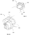
- FIG. 2 illustrates a rear perspective view of an exemplary head protection device, according to some embodiments of the invention.
- FIG. 3 illustrates a front perspective view of the device of FIG. 2 , according to some embodiments of the invention.
- FIG. 4 illustrates a perspective view of the device of FIG. 2 when in an open position, according to some embodiments of the invention.
- FIG. 5 illustrates a perspective exploded view of the device of FIG. 2 , according to some embodiments of the invention.
- FIG. 6 illustrates a magnified perspective view of a portion of a rear wall, and an adjuster unit of a device, according to some embodiments of the invention.
- FIG. 7 illustrates a side view of the device of FIG. 2 when in an open position, according to some embodiments of the invention.
- FIG. 8 illustrates a rear perspective view of the device of FIG. 2 when in a closed position, according to some embodiments of the invention.
- FIG. 9 illustrates a front perspective view of the device of FIG. 2 protecting a head of a user, according to some embodiments of the invention.
- FIG. 10 illustrates a rear perspective view of the device of FIG. 2 protecting a head of a user, according to some embodiments of the invention.
- FIG. 11 illustrates the device of FIG. 2 when in an open position, according to some embodiments of the invention.
- FIG. 12 illustrates an exemplary head protection device with a side opening pivotal movement mechanism, according to some embodiments of the invention.
- FIG. 13 illustrates a front perspective view of an exemplary head protection device with a head protection shield, according to some embodiments of the invention.
- FIG. 14 illustrates a rear perspective view of the head protection device of FIG. 13 , according to some embodiments of the invention.
- FIG. 15 is a flow chart illustration of a method of protecting a person positioned on a patient bed/table, according to some embodiments of the invention.
- the current invention in some embodiments thereof, relates to a dedicated patient head protection device.
- the device creates a physical barrier between the patient's head and face and optionally neck and potentially harmful objects.
- the head protection device may protect the patient's face from moving parts of the C-arm that might collide with it.
- the device is intended to provide full protection for areas of head, face and neck of the patient.
- the head protection device of the invention may confer one or more of the following attributes:
- the head protection device includes a support platform for supporting a patient's head; and a head protection shield connected to the support platform and enclosing a space for accommodating a patient's head.
- the head protection device may be at least partially transparent or translucent, allowing the medical staff to visualize the patient and vice versa.
- the head protection device may include broadcasting and/or communication means to allow communication between the patient and the medical staff.
- broadcasting and/or communication means include a speaker, a microphone, a camera (e.g., a video camera), a display screen or a combination thereof.
- the distance of the shield from the support platform of the head protection device can be conveniently adjusted to fit to various head sizes and shapes.
- an attachment unit e.g., a hinge connecting the shield to the support platform allows convenient opening and closing of the device, optionally via a one dimensional rotation or partial rotation movement.
- the head protection device of the invention may optionally include attachment or fixature means to allow an attachment to a sub-system and/or an add-on system.
- exemplary sub-systems include, without limitation, an X-ray system or a portion thereof (e.g., a C-arm).
- Exemplary add-on systems include, without limitation, radiation shielding apparatuses, the teachings of which are provided in the following disclosures: U.S. Pat. Nos. 8,439,564, and 8,113,713, US patent application No. 2018/0168525, International patent application No. WO 2017/083437, and US patent application No.: 2018/0249972, the content of which are incorporated by reference as if fully set forth herein.
- the head protection device may be made of a material visible to a collision sensor.
- collision sensors include, a capacitive sensor, a resistive sensor, a capacitive-resistive sensor, an ultrasonic sensor, an electro-optic sensor, a contact sensor, a strain sensor, and a combination thereof.
- Non limited examples of materials visible to a collision sensor include carbon fiber and water, or water-based gel which may be implemented herein within dedicated tubes.
- the head protection device includes an adjuster unit for allowing vertical movements of a head protection shield and adjusting the distance of the shield with respect to a patient bed/table/chair.
- Various adjuster mechanisms are contemplated as long as those mechanisms afford the vertical movement of the shield.
- Exemplary mechanisms include sliding mechanisms wherein at least two elements slide with respect to each other and allow an extension of at least one of the elements.
- the sliding mechanism may include a rail and a sliding element.
- Additional exemplary mechanisms include telescopic structures which can extend and retract, scissors lifting mechanism (e.g., scissors lifting jack), a lever, a hydraulic lift mechanism and any of the alike vertical lifting elements/means.
- the above adjuster mechanisms may be motorized, for example, via an electrical motor, a pneumatic motor, a hydraulic motor.
- FIG. 1 schematically illustrates an exemplary C-arm 20 of an X-ray system and an exemplary radiation shielding apparatus 10 which intends to limit/reduce exposure to radiation of personnel and technicians who work with and near X-ray radiation systems, such as C-arm 20 .
- FIG. 1 further illustrates an exemplary head protection apparatus 100 which creates a physical barrier between the patient's head and optionally neck and potentially harmful moving parts of the C-arm 20 and/or radiation shielding apparatus 10 .
- the apparatus 10 is shown in conjunction with a typical C-arm 20 of an X-ray system for performing an X-ray image of a patient.
- the X-ray system includes a radiation source 22 and a radiation detector 24 mounted on opposing ends of C-arm 20 .
- the apparatus includes a radiopaque or radiation attenuating/blocking shield, which includes at least one radiation shield assembly 28 (e.g. above and below the patient, as illustrated) having a support base 30 operatively connectable to radiation source 22 and/or operatively connected to radiation detector 24 , which are mounted on opposite ends of C-arm 20 .
- a radiopaque or radiation attenuating/blocking shield which includes at least one radiation shield assembly 28 (e.g. above and below the patient, as illustrated) having a support base 30 operatively connectable to radiation source 22 and/or operatively connected to radiation detector 24 , which are mounted on opposite ends of C-arm 20 .
- Radiation shield assembly 28 may optionally include a plurality of radiation shield segments 32 sequentially positioned relative to support base 30 , thereby forming radiopaque screen radiation attenuating/blocking shield in a contiguous configuration.
- Shield assembly 28 has free edge ends 38 for spanning the periphery of a body region of the patient. Radiation shield segments 32 are controllable to extend or contract to a selected length to position respective free ends 38 in proximity of the patient, or an object such as an X-ray table.
- a head protection device 100 is further provided to protect a patient head and provide collision protection from moving parts of C-arm 20 and/or radiation shielding apparatus 100 .
- the head protection device 100 includes a head protection shield 102 essentially made of a rigid material which is adjustable in terms of height/distance of the shield with respect to a patient head platform, or support platform (e.g., support platform 104 shown in FIGS. 2 - 12 ).
- FIGS. 2 and 3 illustrate an exemplary head protection device 100 in accordance with embodiments of the current invention.
- FIG. 2 illustrates a rear perspective view of the device 100 .
- FIG. 3 illustrates a front perspective view of the device 100 .
- the device 100 includes a head protection shield 102 , attached to a support platform 104 via a hinge 120 .
- Head protection shield 102 includes a top face protection shield 108 and opposing side protection shields 103 extending downwardly from the top face protection shield 108 .
- the device 100 further includes an adjuster unit 106 for adjusting a distance between face protection shield 108 of shield 102 and support platform 104 .
- the face/head protection shield e.g.
- a mask 108 has two degrees of freedom, i.e., vertical, via adjuster unit 106 , and/or rotational/pivotal, via hinge 120 .
- the face/head protection shield (e.g. a mask) 108 has no more than two degrees of freedom.
- Vertical movement includes, for example, moving shield 102 towards and away from support platform 104 to enable close fit for different head sizes and/or to facilitate maneuvering by a lab staff and equipment.
- Rotational movement includes, for example, rotation around a fulcrum (hinge 120 ) at the bottom of the device near the support platform 104 to enable head positioning.
- all mechanisms are radiolucent and/or non-radiolucent parts (like a hinge) are located behind the patient, and/or on the sides of the patient, and/or between the patient and the support and/or next to the support.
- the face/head protection shield 102 optionally has one or more openings 105 to ensure comfort, relaxing and/or airy environment for the patient.
- the device 100 optionally has features (i.e., attachment means) enabling fixture and/or release and/or movement relative to a patient table
- the support platform 104 may include slots 107 suitable for standard straps, for example, to strap the support platform 104 to a table and/or loosen the support platform 104 from the table for moving and/or to remove the device 100 from the table.
- FIG. 4 device 100 is shown when shield 102 in an open position.
- the support platform 104 includes a base unit 112 and a vertical rear wall 114 extending perpendicular from the support platform 104 and having a front surface 114 a .
- the shield 102 when in an open position allows a patient to place his head on the base unit 112 .
- rear wall 114 is manufactured from a radiation blocking/attenuating material to thereby protect the medical staff from scattered radiation in areas behind the patient's head.
- the rear wall 114 may be manufactured from a radiation attenuating material, such as a radiation attenuating metal (e.g., tungsten, lead, bismuth, antimony, barium, tantalum, and a combination thereof).
- a radiation attenuating metal e.g., tungsten, lead, bismuth, antimony, barium, tantalum, and a combination thereof.
- the rear wall may be manufactured from a composite material comprising a radiation attenuating metal (optionally in the form of a foil or a powder).
- the rear wall may be manufactured from a composite material comprising carbon fiber and a radiation attenuating metal (optionally in the form of a foil).
- the composite material may be in the form of layers of one or more carbon fibers and one or more layers of a radiation attenuating material.
- the composite material may include a binding material (e.g., a thermoset resin) such to act as an adhesive between the layers and contribute to the rigidity and strength of a structure when combined with the fibers.
- the composite material includes a radiation attenuating material in the form of a powder mixed within a binding material, and wherein such mixture is applied onto at least one of the fibers.
- the composite material includes a thermoplastic material mixed with a radiation attenuating material.
- FIG. 5 illustrates a perspective exploded view of device 100 .
- the shield 102 includes a face protector shield 108 for protecting face of the user, and an elongated rod 110 extending from the face protector shield 108 .
- the support platform 104 is pivotably attached to shield 102 via hinge 120 .
- the support platform 104 includes a base unit 112 , a rear wall 114 and a groove 116 .
- the base unit 112 is configured to receive a head of the user.
- the rear wall 114 is extending vertically from the base unit 112 .
- the rear wall 114 is having a front surface ( 114 a , shown in FIG. 4 ) and a rear surface 114 b .
- the rear wall 114 covers the top of the head of a patient.
- the groove 116 is configured on the rear surface 114 b .
- An adjuster unit 106 is configured to allow for a vertical movement of face protector shield 108 with respect to base unit 112 , thereby allowing to adjust the distance between face protector shield 108 and base unit 112 .
- Various mechanisms of an adjuster unit are contemplated and may include, for example, a sliding element which is slidable within a rail or a bracket 118 as will be described herein below in greater details.
- the adjuster unit 106 pivotally attaches via hinge 120 the support platform 104 to the shield 102 .
- the adjuster unit 106 includes a hollow bracket 118 configured to allow sliding therein of a sliding element, herein elongated rod 110 , optionally up to full evacuation of rod 110 and the full release of shield 102 .
- the hollow bracket 118 is configured to fit in the groove 116 .
- the hollow bracket 118 is having an open top end 118 a and a bottom end 118 b .
- the open top end 118 a receives the elongated rod 110 .
- the hinge 120 attaches to the bottom end 118 b to facilitate pivot movement of the shield 102 with respect to the support platform 104 .
- alternative locations of the hinge are contemplated, such as an attachment of hinge 120 to a middle location or a higher location in rear surface 114 b .
- Pivotal movement includes, up to about 90° opening of shield 102 with respect to support platform 104 .
- 45° opening of shield 102 with respect to support platform 104 shown for example in FIG. 7
- the pivotal movement may include, for example, 90° opening of shield 102 with respect to support platform 104 (shown for example in FIG. 11 ).
- a threaded knob 122 can extend through the bracket 118 and configured to lock the vertical movement of shield 102 with respect to support platform 104 .
- FIG. 6 illustrates a rear perspective view of the rear surface 114 b of rear wall 114 , the elongated rod 110 and the adjuster unit 106 .
- the groove 116 configured on the rear wall 114 to receive the hollow bracket 118 .
- the shape of the groove 116 may geometry fit the shape of the hollow bracket 118 .
- a locking member 123 is configured within bracket 118 and locks the vertical movement of the elongated rod 110 inside the hollow bracket 118 .
- the elongated rod 110 further includes one or more grooves/slots 130 to receive an internal tab-like portion (not shown) of locking member 123 and thereby lock the vertical movement of the shield.
- Locking member 123 is made of a resilient material allowing backward retraction thereof to thereby allow the movement of the elongated rod 110 within bracket 118 and adjust the distance of the shield 102 from the support platform 104 to fit various head sizes. When locking member 123 is released it is capable of locking the vertical movement and fixate the height of the elongated rod 110 inside the hollow bracket 118 .
- a knob 122 is further disposed on rear surface 114 b to further stop the vertical movement of the shield 102 with respect to support base 104 .
- Stopper 125 is configured on rear wall 114 b and locks the pivotal movement of shield 10 with respect to support platform 104 by an axial movement thereof.
- FIG. 7 illustrates a side view of device 100 when in an open position.
- a hinge 120 located at the bottom of rear wall 114 facilitates a pivotal movement, herein illustrated as about 45° and allows a patient to position its head on support platform 104 .
- the adjuster unit 106 facilitates adjusting the height of the shield 102 with respect to support platform 104 .
- FIG. 8 illustrates a rear perspective view of the device 100 .
- the shield 102 is in closed position and the locking member 123 when manually retracted backwards allows the sliding of the elongated rod 110 within bracket 118 and when released locks the vertical movement of the elongated rod 110 inside the hollow bracket 118 to thereby adjust the distance of the shield 102 from the support platform 104 to fit various head sizes.
- the face protector shield 108 includes a plurality of openings 105 to allow comfort, relaxing and/or airy environment for the user.
- the openings 105 my form a grill-like pattern, a filter-like pattern or any alternative airy pattern, as long as the obtained products allows an airy environment to the patient.
- the device 100 may include a collision sensor 404 configured in the shield 102 to detect collisions.
- collision sensor 404 include but not limited to a capacitive sensor, a resistive sensor, a capacitive-resistive sensor, an ultrasonic sensor, an electro-optic sensor, a contact sensor, a strain sensor, a temperature sensor (thermocouple), and a combination thereof.
- the device 100 may further include one or more of a speaker 406 to generate audio signals, a microphone 408 to receive audio signals, a camera 410 to capture visuals, a display unit 412 to display visuals, a bi-directional communication unit 414 to communicate the visual and audio signals over a communication network, and a battery 416 to power the bi-directional communication unit 414 , the display unit 412 , the camera 410 , the microphone 408 and/or the speaker 406 .
- the speaker 406 , microphone 408 , camera 410 , display unit 412 , bi-directional communication unit 414 , and/or battery 416 may be disposed on one or more positions in the protector shield 102 or on alternative locations, such as the support platform 104 .
- Examples of a communication network include but are not limited to Wi-Fi, Bluetooth, NFC, cellular etc.
- Examples a battery 416 include but not limited to a lithium ion battery, a lithium/silver vanadium oxide battery, a lithium polymer battery, rechargeable battery or a super-capacitor.
- Examples of a display unit 412 include but not limited to cathode ray tube (CRT) display, a liquid crystal display (LCD) or light emitting diode (LED) display etc.
- FIGS. 9 and 10 illustrate a perspective front view ( FIG. 9 ) and a perspective back view ( FIG. 10 ) of the device 100 protecting upper body of a patient 502 .
- the device 100 may be connected to bed, chair, table, X-ray systems etc. via attachment means (not shown) to connect the support platform 104 or shield 102 to the bed, chair, table, X-ray systems, and/or X-ray radiation shielding apparatus.
- the shield 102 covers the face of the user 502 and is shown in closed position.
- FIG. 11 illustrate the device 100 when the shield 102 fully opened, i.e., the pivotal movement includes, for example, 90° opening of shield 102 with respect to support platform 104 .
- FIG. 12 illustrates yet another exemplary head protection device 200 for protecting the face of a patient 502 , which similarly to device 100 includes a shield 202 pivotally connected via a hinge 220 to a support platform 204 .
- the device includes a vertical side wall 214 extending perpendicular from a base unit 212 and allowing a side pivotal opening of the shield 202 .
- the device 200 includes an adjuster unit (as shown in FIGS. 2 - 11 ) for allowing the adjustment of the distance of shield 202 from support platform 204 .
- FIGS. 13 - 14 illustrate yet another exemplary head protection device 300 for protecting the face of a patient, which is similar to device 100 with the exception that device 300 does not include a base unit (such as base unit 112 shown for example in FIG. 4 ).
- Device 300 includes a shield 302 pivotally connected via a hinge 320 to vertical rear wall 314 .
- the device 300 includes an adjuster mechanism 306 which may be similar to adjuster mechanism 106 of device 100 .
- Device 300 is connectable via attachment means, e.g., straps (not shown) to a patient bed/table/chair.
- the patient positions his head on a head support platform (e.g., patient bed/chair/operation table) and the device is connected to the head support platform or an add-on system or a sub-system such to allow protection of a patient's upper body portion.
- a head support platform e.g., patient bed/chair/operation table
- FIG. 15 is a flow chart illustration of a method of protecting a person positioned on a patient bed/table.
- a head protection device such as device 100
- the device may be opened to facilitate positioning the patient on the support platform and/or closed to shield the patient while the patient is on the support platform.
- the shield may be opened to facilitate the patient moving off the support platform.
- the patient may position himself under or behind the shield without changing the shield's position.
- the shield may be adjusted to shield the patient and/or for comfort of the patient and/or to allow access to the patient and/or to facilitate movement of the patient as necessary for a medical procedure.
- the shield may provide collision protection to one or more parts of a patient.
- a face/head shield may be anchored onto a patient bed/table of an X-ray system.
- the shield is opened, and/or the shield is optionally closed and/or adjusted.
- the shield may be adjusted to be close to the face of the patient.
- part of the shield and/or the entire shield/and/or the inner surface of the shield may be 0 to 2 cm distanced from the patients' face and/or 2 to 5 cm and/or 5 to 10 cm distanced from the patient.
- adjusting the shield to be close to the patient may reduce the interference of the shield to positioning and/or movement of the C-arm or other X-ray equipment.
- the X-ray system may be used to scan the patient and/or his face with reduced risk of collision with his face.
- an x-ray system may visualize parts of the patient through the shield, for example the shield may be made of a radiolucent material with respect to the scanning radiation.
- the shield may be made of a material that is visible to an active collision avoidance system of the X-ray system or a portion thereof. It would be readily apparent to those skilled in the art that various materials such as radiolucent and carbon fibers may be envisioned without deviating from the scope of the present invention.
- a patient may be supported by a table and/or examination chair and/or bed/table and/or chair. Medical personnel may be using heavy and/or dangerous and/or moving equipment around the patient. For example, such a situation commonly occurs with X-ray systems having a moveable C-arm.
- the patient face/head shield includes a shield that protects sensitive parts of the patient from collisions.
- the shield is designed to allow access to the patient for a procedure.
- a face/head shield is mounted on a patient bed/table of an X-ray system.
- the scanning equipment may include moving scanning elements.
- the shield may be positioned over and/or around a face of a patient, for example to protect him from collision with the moving scanning equipment.
- the shield may be made of radiolucent material and/or positioned close to and/or wrapped around the face of the patient for example to avoid interfering with movement and/or functioning of the X-ray system.
- the shield is configured to avoid irritating the patient.
- a face/head shield may have large open spaces to avoid making the patient feel trapped and/or suffocated, and/or to protect the patient from possible collisions with an X-ray system or an X-ray add-on system.
- the device protection device includes a shield, for protecting a portion of a subject from a collision with an object moving relative to the subject and a support platform.
- the device includes fixature means configured to hold the shield rigidly to a patient support device (e.g., patient bed/table) or to the support platform.
- a patient support device e.g., patient bed/table
- an adjustor may be positioned between the shield and the support platform.
- the adjustor may allow movement of the shield with respect to the support platform, for example to facilitate positioning the patient on the support and/or to facilitate movement of the patient on the support platform.
- the adjustment mechanism may be locked, for example holding the shield rigidly to the support for shielding the subject.
- method refers to steps, procedures, manners, means, or/and techniques, for accomplishing a given task including, but not limited to, those steps, procedures, manners, means, or/and techniques, either known to, or readily developed from known steps, procedures, manners, means, or/and techniques, by practitioners in the relevant field(s) of the disclosed invention.
- a numerical value of a parameter, feature, characteristic, object, or dimension may be stated or described in terms of a numerical range format.
- Such a numerical range format illustrates implementation of some exemplary embodiments of the invention, and does not inflexibly limit the scope of the exemplary embodiments of the invention. Accordingly, a stated or described numerical range also refers to, and encompasses, all possible sub-ranges and individual numerical values (where a numerical value may be expressed as a whole, integral, or fractional number) within that stated or described numerical range.
- a stated or described numerical range ‘from 1 to 6’ also refers to, and encompasses, all possible sub-ranges, such as ‘from 1 to 3’, ‘from 1 to 4’, ‘from 1 to 5’, ‘from 2 to 4’, ‘from 2 to 6’, ‘from 3 to 6’, etc., and individual numerical values, such as ‘1’, ‘1.3’, ‘2’, ‘2.8’, ‘3’, ‘3.5’, ‘4’, ‘4.6’, ‘5’, ‘5.2’, and ‘6’, within the stated or described numerical range of ‘from 1 to 6’. This applies regardless of the numerical breadth, extent, or size, of the stated or described numerical range.
- the term ‘about’ is some embodiments, refers to ⁇ 30% of the stated numerical value. In further embodiments, the term refers to ⁇ 20% of the stated numerical value. In yet further embodiments, the term refers to ⁇ 10% of the stated numerical value.
Landscapes
- Health & Medical Sciences (AREA)
- Life Sciences & Earth Sciences (AREA)
- Engineering & Computer Science (AREA)
- Medical Informatics (AREA)
- Optics & Photonics (AREA)
- General Health & Medical Sciences (AREA)
- Veterinary Medicine (AREA)
- Public Health (AREA)
- Biophysics (AREA)
- High Energy & Nuclear Physics (AREA)
- Physics & Mathematics (AREA)
- Nuclear Medicine, Radiotherapy & Molecular Imaging (AREA)
- Animal Behavior & Ethology (AREA)
- Pathology (AREA)
- Radiology & Medical Imaging (AREA)
- Biomedical Technology (AREA)
- Heart & Thoracic Surgery (AREA)
- Molecular Biology (AREA)
- Surgery (AREA)
- Neurology (AREA)
- Neurosurgery (AREA)
- Dentistry (AREA)
- Oral & Maxillofacial Surgery (AREA)
- Pulmonology (AREA)
- Theoretical Computer Science (AREA)
- Apparatus For Radiation Diagnosis (AREA)
Abstract
Description
-
- a support platform; and
- a head protection shield connected to the support platform and enclosing a space for accommodating a patient's head.
-
- a head protection shield;
- an adjuster unit allowing vertical adjustment of the shield relative to a patient's head platform;
- wherein the adjuster unit allows to adjust the space enclosed between the head protection shield and the patient's head platform (e.g., a patient table/bed/chair and a support platform).
-
- a head protection shield comprising a face protector shield;
- a support platform comprising a base unit for receiving a patient head;
- a hinge for pivotably attaching the head protection shield to the support platform; and
- an adjuster unit allowing to vertically adjust the distance between the face protector shield and the base unit, thereby allowing to fit various head sizes.
-
- a head protection shield comprising a face protector shield;
- a vertical rear or side wall;
- a hinge for pivotably attaching the head protection shield to the vertical rear or side wall;
- attachment means to allow coupling the head protection device to a patient head platform; and
- an adjuster unit allowing to vertically adjust the distance between the face protector shield and the patient head platform, thereby allowing to fit various head sizes.
-
- an X-ray radiation shielding apparatus comprising:
- an X-ray radiation shield positioned around an X-ray source of a movable X-ray robotic arm; and
- an X-ray radiation shield positioned around an X-ray detector of a movable X-ray robotic arm; and
- a patient head protection device comprising:
- a head protector shield;
- a support platform comprising a base unit for receiving a patient head;
- a hinge for pivotably attaching the head protection shield to the support platform; and
- an adjuster unit allowing to vertically adjust the distance between the face protector shield and the base unit, thereby allowing to fit various head sizes.
-
- an X-ray radiation shielding apparatus comprising:
- an X-ray radiation shield positioned around an X-ray source of a movable X-ray robotic arm; and
- an X-ray radiation shield positioned around an X-ray detector of a movable X-ray robotic arm; and
- a patient head protection device comprising:
- a head protector shield;
- a vertical rear or side wall;
- a hinge for pivotably attaching the head protection shield to the vertical or side wall; and
- attachment means to allow coupling the head protection device to a patient head platform; and
- an adjuster unit allowing to vertically adjust the distance between the face protector shield and the patient head platform, thereby allowing to fit various head sizes.
-
- providing a head protection device comprising a head protection shield;
- opening the device by a pivotal movement of the shield with respect to a patient head platform;
- positioning a patient's head on the patient head platform;
- closing the head protection device;
- adjusting a height of the head protection shield with respect to the patient head platform using an adjuster unit of the head protection device; and
- performing the medical procedure.
-
- 1. the head protection device is made of a material (e.g. carbon fiber) that provides strong and rigid protection; and/or
- 2. the head protection device is made of a material visible to a collision sensor (for example carbon fiber is visible to a capacitive technology collision detector that may be used on an imaging device); and/or
- 3. the head protection device is made of a material that does not interfere with the equipment in use. For example, a head protection shield may be radiolucent to radiation in a certain band to facilitate imaging using radiation in that band (for example carbon fiber is radiolucent to radiation of some imaging devices for example X-rays); and/or
- 4. the head protection device includes one or more openings to allow an airy environment to a user; and/or
- 5. the head protection device is configured to adjust various head sizes or can be adjusted to allow varying degrees of space to a user.
Claims (21)
Priority Applications (1)
| Application Number | Priority Date | Filing Date | Title |
|---|---|---|---|
| US16/731,548 US12011306B2 (en) | 2019-01-02 | 2019-12-31 | Patient head protection device |
Applications Claiming Priority (2)
| Application Number | Priority Date | Filing Date | Title |
|---|---|---|---|
| US201962787653P | 2019-01-02 | 2019-01-02 | |
| US16/731,548 US12011306B2 (en) | 2019-01-02 | 2019-12-31 | Patient head protection device |
Publications (2)
| Publication Number | Publication Date |
|---|---|
| US20200205754A1 US20200205754A1 (en) | 2020-07-02 |
| US12011306B2 true US12011306B2 (en) | 2024-06-18 |
Family
ID=71122391
Family Applications (1)
| Application Number | Title | Priority Date | Filing Date |
|---|---|---|---|
| US16/731,548 Active 2041-09-06 US12011306B2 (en) | 2019-01-02 | 2019-12-31 | Patient head protection device |
Country Status (7)
| Country | Link |
|---|---|
| US (1) | US12011306B2 (en) |
| EP (1) | EP3905958B1 (en) |
| JP (2) | JP7498970B2 (en) |
| KR (1) | KR102838675B1 (en) |
| CN (1) | CN113939230A (en) |
| ES (1) | ES3031116T3 (en) |
| WO (1) | WO2020142564A1 (en) |
Families Citing this family (7)
| Publication number | Priority date | Publication date | Assignee | Title |
|---|---|---|---|---|
| WO2017083437A1 (en) | 2015-11-09 | 2017-05-18 | Radiaction Ltd. | Radiation shielding apparatuses and applications thereof |
| EP3905958B1 (en) | 2019-01-02 | 2025-05-21 | Radiaction Ltd. | Patient head protection device |
| EP3905959B1 (en) | 2019-01-02 | 2025-12-24 | Radiaction Ltd. | Radiation protection apparatus and materials therefor |
| EP3993705B1 (en) | 2019-07-02 | 2024-07-24 | Radiaction Ltd. | Deployable radiation shield cover |
| CN113197592B (en) * | 2021-06-21 | 2023-08-01 | 吉林大学 | Radiology department is with inspection nursing head protection subassembly |
| KR102702633B1 (en) * | 2022-05-23 | 2024-09-04 | 강원대학교병원 | Medical radiation shielding device |
| CN119033401B (en) * | 2024-11-04 | 2025-02-18 | 南方医科大学南方医院 | A protective device for CT examination bed |
Citations (224)
| Publication number | Priority date | Publication date | Assignee | Title |
|---|---|---|---|---|
| US2593526A (en) | 1950-06-23 | 1952-04-22 | Gen Electric | X-ray shutter |
| US2835824A (en) | 1956-06-26 | 1958-05-20 | Keleket X Ray Corp | X-ray apparatus |
| US3310053A (en) | 1964-03-25 | 1967-03-21 | Norma C Greenwood | Radiation protective girdle |
| US3967129A (en) | 1975-04-28 | 1976-06-29 | Research Corporation | Radiation shielding curtain |
| US3984696A (en) | 1974-12-11 | 1976-10-05 | Medi-Ray, Inc. | Radiation guard for X-ray table |
| US3984695A (en) | 1975-01-06 | 1976-10-05 | Medi-Ray, Inc. | Radiation guard apparatus |
| US4034228A (en) | 1974-09-30 | 1977-07-05 | Siemens Aktiengesellschaft | Tubus for determining the boundaries of a beam of penetrating rays |
| US4062518A (en) | 1976-11-10 | 1977-12-13 | General Electric Company | X-ray shielding device |
| US4122350A (en) | 1977-11-21 | 1978-10-24 | Julius Lipthay | Adjustable collimator for mammography |
| US4140129A (en) | 1977-04-13 | 1979-02-20 | Applied Radiation Corporation | Beam defining system in an electron accelerator |
| US4210811A (en) | 1975-11-03 | 1980-07-01 | Heimann Gmbh | Drive for moveable shield in luggage screening apparatus |
| US4400820A (en) | 1982-09-30 | 1983-08-23 | General Electric Company | Axial tomography head holder |
| US4581538A (en) | 1983-09-30 | 1986-04-08 | Colonial X-Ray Corporation | Radiation shield |
| US4587277A (en) | 1983-04-04 | 1986-05-06 | Yukiyasu Unno | Radiation shield |
| US4795654A (en) | 1984-11-05 | 1989-01-03 | Innofinance Altalanos Innovacios Penzintezet | Structure for shielding X-ray and gamma radiation |
| US4837796A (en) | 1985-04-30 | 1989-06-06 | Kabushiki Kaisha Toshiba | X-ray imaging system |
| US4938233A (en) | 1987-08-03 | 1990-07-03 | Techton, Inc. | Radiation shield |
| EP0393214A1 (en) | 1989-04-17 | 1990-10-24 | Siemens Aktiengesellschaft | Radiodiagnostic apparatus with a radiation protection device |
| US4969170A (en) | 1988-09-26 | 1990-11-06 | Mitsubishi Denki Kabushiki Kaisha | Collision preventive device for medical equipment |
| US4977585A (en) | 1989-04-05 | 1990-12-11 | Imatron, Inc. | Self shielded computerized tomographic scanner |
| US5006718A (en) | 1989-07-21 | 1991-04-09 | Lenhart Mark J | X-ray shield for X-ray examination table |
| US5099134A (en) | 1988-05-27 | 1992-03-24 | Kabushiki Kaisha Toshiba | Collimator and a method of producing a collimator for a scintillator |
| US5299243A (en) | 1991-12-24 | 1994-03-29 | Cogema-Compagnie Generale Des Matieres Nucleaires | Glove holder unit for a confinement enclosure |
| US5335366A (en) | 1993-02-01 | 1994-08-02 | Daniels John J | Radiation shielding apparatus for a radio transmitting device |
| US5417225A (en) | 1993-09-03 | 1995-05-23 | Georgetown University | Surgical radiation shield having an opening for tube insertion and a slit for shield removal without tube removal |
| JPH0739805U (en) | 1993-12-27 | 1995-07-18 | 千葉商事株式会社 | Animal X-ray diagnostic protection device |
| US5438705A (en) | 1994-05-04 | 1995-08-08 | Mendez; Arturo | Honey bee protective bag |
| WO1996001591A1 (en) | 1994-07-08 | 1996-01-25 | Microvena Corporation | Method of forming medical devices; intravascular occlusion devices |
| US5523578A (en) | 1995-03-22 | 1996-06-04 | Herskovic; Arnold | Electromagnetic radiation shielding arrangement and method for radiation therapy patients |
| US5525408A (en) | 1993-10-13 | 1996-06-11 | Weir; Donald | Radiation - shielding material |
| US5570770A (en) | 1992-09-14 | 1996-11-05 | U.S. Philips Corporation | Apparatus, in particular an x-ray examination apparatus, with arrangement for collision protection |
| FR2736256A1 (en) | 1995-07-05 | 1997-01-10 | Apelem | Radiological examination equipment - using X ray emitter and receiver mounted on arc which may be rotated and translated |
| US5651044A (en) | 1995-10-02 | 1997-07-22 | General Electric Company | Capacitive proximity detector for radiation imager position control |
| US5769816A (en) | 1995-11-07 | 1998-06-23 | Embol-X, Inc. | Cannula with associated filter |
| US5769819A (en) | 1997-04-24 | 1998-06-23 | Medtronic, Inc. | Catheter distal tip component |
| US5848449A (en) * | 1997-05-05 | 1998-12-15 | Biotek | Slide lock device and method for securing a patient positioning mold |
| US5900638A (en) | 1996-03-26 | 1999-05-04 | Siemens Aktiengesellschaft | Radiation protection arrangement for an x-ray diagnostics installation |
| US5937028A (en) | 1997-10-10 | 1999-08-10 | Analogic Corporation | Rotary energy shield for computed tomography scanner |
| US5947981A (en) | 1995-01-31 | 1999-09-07 | Cosman; Eric R. | Head and neck localizer |
| US5981964A (en) | 1997-12-22 | 1999-11-09 | Bruce J. McAuley | Adjustable X-ray shield and on-line dosimetry system using same |
| US6003174A (en) | 1997-09-03 | 1999-12-21 | Kantrowitz; Allen | Radiolucent table extension and method |
| US6083239A (en) | 1998-11-24 | 2000-07-04 | Embol-X, Inc. | Compliant framework and methods of use |
| US6120534A (en) | 1997-10-29 | 2000-09-19 | Ruiz; Carlos E. | Endoluminal prosthesis having adjustable constriction |
| US6139517A (en) | 1997-12-15 | 2000-10-31 | Cardeon Corporation | Perfusion shunt apparatus and method |
| DE19924914A1 (en) | 1999-05-31 | 2000-12-21 | Lozano Saavedra Jeremias | Transportable radiation protection unit, consists of radiation protection wall composed of combination of transparent and opaque material |
| CN1278713A (en) | 1997-11-07 | 2001-01-03 | 萨尔维亚克有限公司 | An embolic protection device |
| JP2001037751A (en) | 1999-07-16 | 2001-02-13 | Siemens Ag | Bed apparatus for X-ray diagnostic equipment |
| US6245012B1 (en) | 1999-03-19 | 2001-06-12 | Nmt Medical, Inc. | Free standing filter |
| US6254563B1 (en) | 1997-12-15 | 2001-07-03 | Cardeon Corporation | Perfusion shunt apparatus and method |
| US6254633B1 (en) | 1997-02-12 | 2001-07-03 | Corvita Corporation | Delivery device for a medical device having a constricted region |
| US6258120B1 (en) | 1997-12-23 | 2001-07-10 | Embol-X, Inc. | Implantable cerebral protection device and methods of use |
| US6281515B1 (en) | 1998-12-07 | 2001-08-28 | Meridian Research And Development | Lightweight radiation protective garments |
| US6325538B1 (en) | 2000-03-17 | 2001-12-04 | Christian M. Heesch | Radiation field isolator apparatus |
| US20020003854A1 (en) | 1997-11-26 | 2002-01-10 | Andrew J. Ivan | Fluoro-assist feature for a diagnostic imaging device |
| CN1331956A (en) | 2001-07-06 | 2002-01-23 | 周星 | Reusable temporary thrombus filter |
| US20020015471A1 (en) | 2000-07-27 | 2002-02-07 | Shigeki Yagi | X-ray fluorescence analyzer |
| US6352363B1 (en) | 2001-01-16 | 2002-03-05 | Stereotaxis, Inc. | Shielded x-ray source, method of shielding an x-ray source, and magnetic surgical system with shielded x-ray source |
| US6361545B1 (en) | 1997-09-26 | 2002-03-26 | Cardeon Corporation | Perfusion filter catheter |
| US6371935B1 (en) | 1999-01-22 | 2002-04-16 | Cardeon Corporation | Aortic catheter with flow divider and methods for preventing cerebral embolization |
| US20020048089A1 (en) | 2000-01-21 | 2002-04-25 | Brown Rayford K. | Anesthetic alleviation by sensory stimulation |
| US6448571B1 (en) | 2000-08-15 | 2002-09-10 | James A. Goldstein | Radiation protection system |
| US6456684B1 (en) | 1999-07-23 | 2002-09-24 | Inki Mun | Surgical scanning system and process for use thereof |
| US6481888B1 (en) | 1999-10-12 | 2002-11-19 | R. Hank Morgan | Scatter ban drape |
| US20020193686A1 (en) | 2000-01-10 | 2002-12-19 | Pinhas Gilboa | Methods and systems for performing medical procedures with reference to projective image and with respect to pre-stored images |
| US6537297B2 (en) | 1997-05-08 | 2003-03-25 | Embol-X, Inc. | Methods of protecting a patient from embolization during surgery |
| US6547760B1 (en) | 1998-08-06 | 2003-04-15 | Cardeon Corporation | Aortic catheter with porous aortic arch balloon and methods for selective aortic perfusion |
| US20030084512A1 (en) * | 2001-10-30 | 2003-05-08 | Kabushiki Kaisha Toshiba | Bed apparatus for image diagnosis and its attachments |
| US20030100940A1 (en) | 2001-11-23 | 2003-05-29 | Mindguard Ltd. | Implantable intraluminal protector device and method of using same for stabilizing atheromas |
| US20030112924A1 (en) | 2001-12-18 | 2003-06-19 | Siemens Aktiengesellschaft | Radiation diaphragm for an X-ray apparatus |
| WO2003073939A1 (en) | 2002-03-01 | 2003-09-12 | Mamea Imaging Ab | X-ray protection device |
| CN1442117A (en) | 2003-01-28 | 2003-09-17 | 沈阳东软数字医疗系统股份有限公司 | Head support for medical treatment and diagnosis bed |
| US20030174802A1 (en) | 1994-08-25 | 2003-09-18 | John Thomas Hare | Moulded radiation shield |
| US6636757B1 (en) | 2001-06-04 | 2003-10-21 | Surgical Navigation Technologies, Inc. | Method and apparatus for electromagnetic navigation of a surgical probe near a metal object |
| US6674087B2 (en) | 2001-01-31 | 2004-01-06 | Worldwide Innovations & Technologies, Inc. | Radiation attenuation system |
| US20040020829A1 (en) | 2002-05-24 | 2004-02-05 | Institut Francais Du Petrole | Catalyst for hydrorefining and/or hydroconversion and its use in hydrotreatment processes for batches containing hydrocarbons |
| US20040029998A1 (en) | 2000-06-20 | 2004-02-12 | Hitoshi Tomita | Radiation shielding material |
| US6692513B2 (en) | 2000-06-30 | 2004-02-17 | Viacor, Inc. | Intravascular filter with debris entrapment mechanism |
| US20040042587A1 (en) | 2002-08-30 | 2004-03-04 | Deshpande Piyush Vijay | Anti-collision method and apparatus for use with C-arm x-ray machine |
| US6703632B1 (en) | 1999-06-01 | 2004-03-09 | The Cleveland Clinic Foundation | Radiation shield |
| WO2004019817A1 (en) | 2002-08-27 | 2004-03-11 | Amir Belson | Embolic protection device |
| US6709415B2 (en) | 1997-09-23 | 2004-03-23 | Biosud S.A. | Intraluminal catheter with expandable tubular open-walled element |
| US6712834B2 (en) | 1998-06-16 | 2004-03-30 | Mindguard Ltd. | Implantable blood filtering device |
| US6718008B1 (en) | 2002-04-22 | 2004-04-06 | Bruker Axs, Inc. | X-ray diffraction screening system with retractable x-ray shield |
| JP2004264207A (en) | 2003-03-03 | 2004-09-24 | Rikuto:Kk | Coverlet for protection from x-ray |
| US20040208291A1 (en) | 2003-04-21 | 2004-10-21 | Stout Fred T. | Portable x-ray table |
| US6828578B2 (en) | 1998-12-07 | 2004-12-07 | Meridian Research And Development | Lightweight radiation protective articles and methods for making them |
| US20040257744A1 (en) | 2003-06-23 | 2004-12-23 | Bushko Wit Cezary | Collision avoidance system and method |
| US6841791B2 (en) | 1998-12-07 | 2005-01-11 | Meridian Research And Development | Multiple hazard protection articles and methods for making them |
| US20050070779A1 (en) | 2003-09-30 | 2005-03-31 | Ram Kishan Singh B | Compact bumper system for imaging device |
| JP2005177047A (en) | 2003-12-18 | 2005-07-07 | Shimadzu Corp | Arm-driven radiation tomography system |
| US20050213713A1 (en) | 2004-03-25 | 2005-09-29 | Worldwide Innovations & Technologies, Inc. | Radiation attenuation system |
| US20050236588A1 (en) | 2004-04-21 | 2005-10-27 | Moshe Ein-Gal | Radiation shield capsule |
| US20050283186A1 (en) | 2002-03-12 | 2005-12-22 | Ev3 Inc. | Everted filter device |
| WO2006026646A1 (en) | 2004-08-31 | 2006-03-09 | Medical Positioning, Inc. | Imaging table support surface |
| US7029175B2 (en) | 2003-05-19 | 2006-04-18 | Ge Medical Systems Global Technology Company, Llc | Method and apparatus for object collision detection utilizing a PID controller in a motorized, mobile C-arm |
| US20060097734A1 (en) | 2002-09-06 | 2006-05-11 | Nanotec Solution | Proximity detector comprising capacitive sensor |
| US7044958B2 (en) | 2001-04-03 | 2006-05-16 | Medtronic Vascular, Inc. | Temporary device for capturing embolic material |
| US7057194B2 (en) | 2004-04-07 | 2006-06-06 | Eco Cath-Lab Systems, Inc. | Radiation barrier |
| WO2006092078A1 (en) | 2005-03-01 | 2006-09-08 | Yue Ma | X-ray device |
| US7108422B2 (en) | 2003-08-25 | 2006-09-19 | Borom Andrew H | Integrated surgical table drape |
| US20060251219A1 (en) | 2005-05-04 | 2006-11-09 | Worldwide Innovations & Technologies, Inc. | Radiation attenuation system |
| US20060262898A1 (en) | 2005-05-20 | 2006-11-23 | Varian Medical Systems, Inc. | System and method for imaging and treatment of tumorous tissue in breasts using computed tomography and radiotherapy |
| US20060287668A1 (en) | 2005-06-16 | 2006-12-21 | Fawzi Natalie V | Apparatus and methods for intravascular embolic protection |
| US7196023B2 (en) | 2003-04-10 | 2007-03-27 | Kappler, Inc. | Chemically resistant radiation attenuation barrier |
| US20070086570A1 (en) | 2005-10-13 | 2007-04-19 | Martin Spahn | Medical imaging system and anti-collision method with a controllable arm |
| WO2007060561A2 (en) | 2005-11-23 | 2007-05-31 | Koninklijke Philips Electronics N.V. | Radiation shielding for tomographic scanners |
| US7232453B2 (en) | 2001-12-05 | 2007-06-19 | Sagax, Inc. | Endovascular device for entrapment of particulate matter and method for use |
| US20070189442A1 (en) | 2006-02-14 | 2007-08-16 | Predrag Sukovic | Self-shielded ct scanner |
| US20070242805A1 (en) | 2004-08-31 | 2007-10-18 | Koninklijke Philips Electronics, N.V. | Proximity Sensor for X-Ray Apparatus |
| US7294845B2 (en) | 2003-06-05 | 2007-11-13 | Mavig Gmbh | Radiation protection arrangement comprising a separable cover |
| US20070269012A1 (en) | 2004-08-31 | 2007-11-22 | Koninklijke Philips Electronics, N.V. | Proximity Sensor for X-Ray Apparatus |
| US7331712B2 (en) | 2003-07-17 | 2008-02-19 | Siemens Aktiengesellschaft | X-ray examination apparatus that is convertible among multiple examination configurations |
| JP2008079728A (en) | 2006-09-26 | 2008-04-10 | Fujifilm Corp | Radiation image information imaging device |
| CN101164637A (en) | 2006-10-16 | 2008-04-23 | 重庆融海超声医学工程研究中心有限公司 | An Ultrasonic Therapy System That Reduces Electromagnetic Interference to Imaging Equipment |
| US20080119722A1 (en) | 2006-11-22 | 2008-05-22 | Swaney Charles M | Body compression device for medical imaging |
| US7420193B2 (en) | 2005-08-05 | 2008-09-02 | Treuth Mark G | Radiation shield |
| US20080258929A1 (en) | 2007-04-20 | 2008-10-23 | Siemens Aktiengesellschaft | Method for monitoring movement with a medical installation and associated medical installation |
| US7441954B2 (en) | 2005-02-15 | 2008-10-28 | Siemens Aktiengesellschaft | Radiation image capture apparatus |
| WO2008140486A2 (en) | 2006-11-11 | 2008-11-20 | Amir Belson | Fluoroscopy operator protection device |
| US7465947B2 (en) | 2006-05-01 | 2008-12-16 | Martin Yale Magram | X-ray shield arrangement for operating room |
| US20090088327A1 (en) | 2006-10-06 | 2009-04-02 | Roberto Rigatti | Method for sequencing a polynucleotide template |
| CN201216602Y (en) | 2008-05-29 | 2009-04-08 | 张铁骑 | Sternum shielding device suitable for sickbed patients |
| US7537600B2 (en) | 2003-06-12 | 2009-05-26 | Boston Scientific Scimed, Inc. | Valved embolic protection filter |
| JP2009232339A (en) | 2008-03-25 | 2009-10-08 | Toshiba Corp | Mobile terminal device |
| US20090325172A1 (en) | 2002-12-23 | 2009-12-31 | Solexa Limited | Modified nucleotides |
| US20100010535A1 (en) | 2008-07-14 | 2010-01-14 | Boston Scientific Scimed, Inc. | Embolic protection device |
| US20100028885A1 (en) | 2001-12-04 | 2010-02-04 | Shankar Balasubramanian | Labelled nucleotides |
| US20100061509A1 (en) | 2006-11-20 | 2010-03-11 | Koninklijke Philips Electronics N. V. | Detector head proximity sensing and collision avoidance apparatuses and methods |
| US20100094119A1 (en) * | 2007-02-28 | 2010-04-15 | University Of Maryland, Baltimore | Method and equipment for image-guided stereotactic radiosurgery of breast cancer |
| US20100163758A1 (en) | 2006-10-11 | 2010-07-01 | Ira Kirschenbaum | Short use system and method for adaptive radiation protection |
| US7829873B2 (en) | 2006-07-28 | 2010-11-09 | Eco Cath-Lab Systems, Inc. | Lower shield for radiation protection system |
| US7837385B2 (en) | 2006-08-10 | 2010-11-23 | Siemens Aktiengesellschaft | Method for recording X-ray images by means of a robotically controlled C-arm system and recording device for recording X-ray images |
| US20100312268A1 (en) | 2006-11-29 | 2010-12-09 | Amir Belson | Embolic protection device |
| US7857512B2 (en) | 2007-06-04 | 2010-12-28 | Siemens Aktiengesellschaft | Collision protection device for a patient examination table of a medical x-ray device |
| US7897949B2 (en) | 2006-06-23 | 2011-03-01 | Mavig Gmbh | Laminated lead-free X-ray protection material |
| JP2011511265A (en) | 2007-12-13 | 2011-04-07 | コーニンクレッカ フィリップス エレクトロニクス エヌ ヴィ | Capacitive type proximity sensor |
| US8052717B2 (en) | 2008-07-14 | 2011-11-08 | Boston Scientific Scimed, Inc. | Embolic protection device |
| US20110314594A1 (en) * | 2005-06-17 | 2011-12-29 | Artisent, Inc. | Hinged Attachment of Headgear to a Helmet |
| US8123779B2 (en) | 2002-12-30 | 2012-02-28 | Boston Scientific Scimed, Inc. | Embolic protection device |
| KR20120084574A (en) | 2011-01-20 | 2012-07-30 | (주) 태웅메디칼 | Shielding cover of x - ray radiography |
| US20120271340A1 (en) | 2011-04-25 | 2012-10-25 | Medtronic, Inc. | Method and Apparatus for Embolic Protection During Heart Procedure |
| US8298258B2 (en) | 2009-10-05 | 2012-10-30 | Boston Scientific Scimed, Inc | Embolic protection device |
| US8337519B2 (en) | 2003-07-10 | 2012-12-25 | Boston Scientific Scimed, Inc. | Embolic protection filtering device |
| CN202665566U (en) | 2012-07-02 | 2013-01-16 | 于红 | Bedside X-ray photography anti-ray-leakage device |
| US8382788B2 (en) | 2008-06-23 | 2013-02-26 | Lumen Biomedical, Inc. | Embolic protection during percutaneous heart valve replacement and similar procedures |
| US8420902B2 (en) | 2010-07-30 | 2013-04-16 | Monsanto Technology Llc | Soybean variety A1024640 |
| CN103045983A (en) | 2012-12-27 | 2013-04-17 | 大连理工大学 | Preparation method of carbon fiber-based high-temperature heat insulation material with tungsten coating on the surface |
| US20130129449A1 (en) | 2010-06-03 | 2013-05-23 | Shoei Co., Ltd. | Structure for mounting anti-fog sheet to shield |
| US8460777B2 (en) | 2008-10-07 | 2013-06-11 | Alliant Techsystems Inc. | Multifunctional radiation-hardened laminate |
| US20130204113A1 (en) | 2010-10-13 | 2013-08-08 | Koninklijke Philips Electronics N.V. | Multi-modality compact bore imaging system |
| US20130267993A1 (en) | 2006-09-11 | 2013-10-10 | Edwards Lifesciences Ag | Embolic protection device and method of use |
| US20130270462A1 (en) | 2011-02-22 | 2013-10-17 | Thomas J. Beck | Practical design for a walk-around, hands-free radiation protective shielding garment suspension apparatus |
| CN203303071U (en) | 2013-06-26 | 2013-11-27 | 曹磊 | CT (Computed Tomography) examining table |
| CN203341747U (en) | 2013-05-09 | 2013-12-18 | 刘放 | Bedside X-ray machine protective cover |
| US20140000091A1 (en) | 2010-12-21 | 2014-01-02 | BiO2 Medical, Inc. | Configuration and method for fixation of a filter to a catheter |
| US8639564B2 (en) | 2008-04-25 | 2014-01-28 | Cisco Technology, Inc. | Advertisement campaign system using socially collaborative filtering |
| US20140029720A1 (en) | 2012-07-30 | 2014-01-30 | Azriel Binyamin Osherov | Movable shield for reducing radiation exposure of medical personnel |
| DE102012212104A1 (en) | 2012-07-11 | 2014-01-30 | Siemens Aktiengesellschaft | Radiation protection device for lower body radiation protection on patient positioning device of medical x-ray machine, has x-ray protective screening surface, which is arranged on patient positioning device |
| US20140048730A1 (en) | 2012-08-15 | 2014-02-20 | Eco Cath-Lab Systems, Inc. | Radiation Protection System |
| US8740930B2 (en) | 2009-02-25 | 2014-06-03 | Medtronic Vascular, Inc. | Embolic filter device independent of treatment device |
| US20140214069A1 (en) | 2013-01-30 | 2014-07-31 | Edwards Lifesciences Corporation | Inflatable Embolic Deflector |
| US20140249568A1 (en) | 2013-03-01 | 2014-09-04 | Aga Medical Corporation | Embolic protection pass through tube |
| US20140275998A1 (en) | 2013-03-15 | 2014-09-18 | Mediguide Ltd. | Medical device navigation system |
| CN203898342U (en) | 2014-06-19 | 2014-10-29 | 刘黎明 | X-ray protector with functions of stretching and mobile positioning |
| US20140334608A1 (en) | 2013-05-08 | 2014-11-13 | Harald Mulzer | Medical Treatment or Examination Device |
| US20140332701A1 (en) | 2009-06-22 | 2014-11-13 | Contour Fabricators, Inc. | Surgical Drape and Method Providing A Sterile Surface Therewith |
| US8903038B2 (en) | 2011-03-09 | 2014-12-02 | Kabushiki Kaisha Toshiba | X-ray CT device |
| CN204016322U (en) | 2014-08-18 | 2014-12-17 | 刘国浩 | The anti-ray protector of combination type for CT examination |
| US20150006607A1 (en) | 2013-06-27 | 2015-01-01 | Tencent Technology (Shenzhen) Company Limited | Method, mobile terminal and system for displaying picture based on wireless network, and storage medium |
| DE102013214222A1 (en) | 2013-07-19 | 2015-01-22 | Siemens Aktiengesellschaft | Stray radiation protection for an X-ray system |
| US8968354B2 (en) | 2011-10-26 | 2015-03-03 | Boston Scientific Scimed, Inc. | Extended protection embolic filter |
| US20150117615A1 (en) | 2013-10-30 | 2015-04-30 | Franz Dirauf | Collision Sensor Device for a Medical Apparatus, and Medical Apparatus |
| US20150128727A1 (en) | 2013-11-11 | 2015-05-14 | Siemens Aktiengesellschaft | Surface-mounted collision sensor, and method for collision detection |
| US9038219B2 (en) | 2012-07-31 | 2015-05-26 | Siemens Aktiengesellschaft | Patient support apparatus and also a positioning method for positioning a patient's head within a surgical head restraint unit |
| KR20150099969A (en) | 2014-02-24 | 2015-09-02 | 남부대학교산학협력단 | Scattering X-ray shield apparatus of the X-ray tube |
| US9144485B2 (en) | 2003-10-06 | 2015-09-29 | Medtronic 3F Therapeutics, Inc. | Method and assembly for distal embolic protection |
| US20150305694A1 (en) | 2012-12-11 | 2015-10-29 | Kabushiki Kaisha Toshiba | X-ray diagnostic apparatus and foot switch used for the same |
| DE102014215448B3 (en) | 2014-08-05 | 2015-12-10 | Siemens Aktiengesellschaft | Imaging device with scattered radiation protection |
| US20150359505A1 (en) | 2014-06-11 | 2015-12-17 | Canon Kabushiki Kaisha | Radiation imaging apparatus, method for controlling the same, and storage medium |
| US20150366650A1 (en) | 2012-11-23 | 2015-12-24 | Venus Medtech (Hangzhou) Inc. | Thrombus Filter and Utilization Method Thereof |
| US20160038365A1 (en) | 2013-07-21 | 2016-02-11 | Trans-Radial Solutions Llc | Left radial access, right room operation, peripheral intervention system |
| US20160143600A1 (en) | 2014-11-26 | 2016-05-26 | Verena Schmidt | Arrangement with a Collision Detection Device, Medical Imaging Apparatus with a Collision Detection Device, and Method for Operating a Collision Detection Device |
| US20160150837A1 (en) | 2013-03-15 | 2016-06-02 | Xodus Medical, Inc. | Patient Protection System Configured to Protect the Head of a Patient |
| US20160158082A1 (en) | 2014-12-05 | 2016-06-09 | Egg Medical, Inc. | Multimodality Medical Procedure Mattress-Based Device |
| JP2016107655A (en) | 2014-12-02 | 2016-06-20 | トヨタ車体株式会社 | Tool for assisting occupant to get in/out from vehicle |
| US20160193731A1 (en) | 2015-01-02 | 2016-07-07 | Stefan Sattler | Robotic medical apparatus with collision detection and method for collision detection in a robotic medical apparatus |
| US20160286890A1 (en) | 2015-03-30 | 2016-10-06 | Sport Maska Inc. | Helmet and visor assembly |
| US20160317277A1 (en) | 2006-09-11 | 2016-11-03 | Edwards Lifesciences Corporation | Embolic deflection device |
| US9492265B2 (en) | 2012-01-06 | 2016-11-15 | Emboline, Inc. | Integrated embolic protection devices |
| US20160345929A1 (en) | 2014-02-05 | 2016-12-01 | Intuitive Surgical Operations, Inc. | System and method for dynamic virtual collision objects |
| CN205959627U (en) | 2016-06-03 | 2017-02-15 | 上海奕瑞光电子科技有限公司 | Carbon fiber product's flat panel detector containing possesses radiation protection ability |
| WO2017083437A1 (en) | 2015-11-09 | 2017-05-18 | Radiaction Ltd. | Radiation shielding apparatuses and applications thereof |
| WO2017116828A1 (en) | 2015-12-29 | 2017-07-06 | Emboline, Inc. | Multi-access intraprocedural embolic protection device |
| US20170220709A1 (en) | 2016-02-03 | 2017-08-03 | Varian Medical Systems, Inc. | System and method for collision avoidance in medical systems |
| US9744023B2 (en) | 2011-10-25 | 2017-08-29 | Boston Scientific Scimed, Inc. | Embolic debris deflector |
| US20170265824A1 (en) * | 2014-12-04 | 2017-09-21 | Trans-Radial Solutions Llc | Radiation shield assembly |
| US20170278585A1 (en) | 2014-08-28 | 2017-09-28 | Rich Media Institute | Electromagnetic Radiation Shielding Tile |
| CN107224297A (en) | 2017-06-02 | 2017-10-03 | 青岛市第三人民医院 | A kind of dept. of radiology children protect fixing device with inspection |
| JP2017181375A (en) | 2016-03-31 | 2017-10-05 | 住友ベークライト株式会社 | Foam and method for producing foam |
| US20170347978A1 (en) | 2016-06-06 | 2017-12-07 | Storz Medical Ag | Urology table with tiltable x-ray tube |
| US20180000431A1 (en) | 2012-05-08 | 2018-01-04 | Biosensors International Group, Ltd. | Collimator |
| WO2018007437A1 (en) | 2016-07-06 | 2018-01-11 | Koninklijke Philips N.V. | Radiation system |
| US20180029972A1 (en) | 2014-12-19 | 2018-02-01 | Thomas P. Daly | Ethyl Benzyl Quaternary Amines of Amido Amines for Improved Antifungal properties |
| CN108309664A (en) | 2018-03-16 | 2018-07-24 | 商丘医学高等专科学校 | A kind of paediatrics rescue monitor device based on platform of internet of things |
| US20180206970A1 (en) | 2016-11-22 | 2018-07-26 | Boston Scientific Scimed, Inc. | Embolic protection device |
| US20180214100A1 (en) | 2017-01-31 | 2018-08-02 | General Electric Company | Robotic arm with x-ray source |
| US20180227468A1 (en) * | 2014-07-31 | 2018-08-09 | Bell Sports, Inc. | Helmet with integrated electronics and helmet visor controls |
| US20180250183A1 (en) | 2017-03-06 | 2018-09-06 | Neural Analytics, Inc. | Headset system |
| JP6391149B2 (en) | 2014-05-28 | 2018-09-19 | 東レ・デュポン株式会社 | Radiation shielding composite film |
| US20180289342A1 (en) | 2015-05-28 | 2018-10-11 | Koninklijke Philips N.V. | Object approach detection for use with medical diagnostic apparatus |
| WO2018232037A1 (en) | 2017-06-14 | 2018-12-20 | Eaves Christopher | Fluoroscope with movable head and barrier to vary source to skin distance |
| US20190015152A1 (en) | 2017-07-17 | 2019-01-17 | Medtronic, Inc. | Reverse irrigation for embolic mitigation |
| US20190038377A1 (en) * | 2017-04-20 | 2019-02-07 | Brainlab Ag | Cranial immobilization system |
| US20190059852A1 (en) * | 2017-08-25 | 2019-02-28 | Neural Analytics, Inc. | Portable headset |
| WO2020142556A1 (en) | 2019-01-02 | 2020-07-09 | Yifat Jonathan | Radiation protection apparatus and materials therefor |
| WO2020142564A1 (en) | 2019-01-02 | 2020-07-09 | Yifat Jonathan | Patient head protection device |
| WO2021003191A1 (en) | 2019-07-02 | 2021-01-07 | Yifat Jonathan | Deployable radiation shield cover |
| US20210283425A1 (en) * | 2018-11-30 | 2021-09-16 | Auracare Co., Ltd. | Radiography and radiotherapy apparatus |
| US20210321885A1 (en) * | 2020-04-21 | 2021-10-21 | Zybergraph Llc | Bio shield for dental chair |
| US20210354610A1 (en) * | 2020-05-17 | 2021-11-18 | James L. Orrington, II D.D.S., P.C. | System for minimizing risk of transmission of infection |
| US11179287B1 (en) * | 2020-06-15 | 2021-11-23 | Majid Mirbahaeddin | Protective shield system |
| US20210369383A1 (en) * | 2020-05-29 | 2021-12-02 | Jason Pawlowicz | Face Shield Protection Device |
| US20220071576A1 (en) | 2017-08-11 | 2022-03-10 | Intervention For Life, Llc | Radiation Shielding System |
| US11744529B2 (en) | 2019-01-02 | 2023-09-05 | Radiaction Ltd. | Supplementary collision detection and prevention system for a medical imager |
-
2019
- 2019-12-31 EP EP19907635.7A patent/EP3905958B1/en active Active
- 2019-12-31 US US16/731,548 patent/US12011306B2/en active Active
- 2019-12-31 WO PCT/US2019/069162 patent/WO2020142564A1/en not_active Ceased
- 2019-12-31 ES ES19907635T patent/ES3031116T3/en active Active
- 2019-12-31 CN CN201980093456.8A patent/CN113939230A/en active Pending
- 2019-12-31 KR KR1020217024195A patent/KR102838675B1/en active Active
- 2019-12-31 JP JP2021538749A patent/JP7498970B2/en active Active
-
2024
- 2024-05-27 JP JP2024085485A patent/JP2024100993A/en not_active Withdrawn
Patent Citations (262)
| Publication number | Priority date | Publication date | Assignee | Title |
|---|---|---|---|---|
| US2593526A (en) | 1950-06-23 | 1952-04-22 | Gen Electric | X-ray shutter |
| US2835824A (en) | 1956-06-26 | 1958-05-20 | Keleket X Ray Corp | X-ray apparatus |
| US3310053A (en) | 1964-03-25 | 1967-03-21 | Norma C Greenwood | Radiation protective girdle |
| US4034228A (en) | 1974-09-30 | 1977-07-05 | Siemens Aktiengesellschaft | Tubus for determining the boundaries of a beam of penetrating rays |
| US3984696A (en) | 1974-12-11 | 1976-10-05 | Medi-Ray, Inc. | Radiation guard for X-ray table |
| US3984695A (en) | 1975-01-06 | 1976-10-05 | Medi-Ray, Inc. | Radiation guard apparatus |
| US3967129A (en) | 1975-04-28 | 1976-06-29 | Research Corporation | Radiation shielding curtain |
| US4210811A (en) | 1975-11-03 | 1980-07-01 | Heimann Gmbh | Drive for moveable shield in luggage screening apparatus |
| US4062518A (en) | 1976-11-10 | 1977-12-13 | General Electric Company | X-ray shielding device |
| US4140129A (en) | 1977-04-13 | 1979-02-20 | Applied Radiation Corporation | Beam defining system in an electron accelerator |
| US4122350A (en) | 1977-11-21 | 1978-10-24 | Julius Lipthay | Adjustable collimator for mammography |
| US4400820A (en) | 1982-09-30 | 1983-08-23 | General Electric Company | Axial tomography head holder |
| US4587277A (en) | 1983-04-04 | 1986-05-06 | Yukiyasu Unno | Radiation shield |
| US4581538A (en) | 1983-09-30 | 1986-04-08 | Colonial X-Ray Corporation | Radiation shield |
| US4795654A (en) | 1984-11-05 | 1989-01-03 | Innofinance Altalanos Innovacios Penzintezet | Structure for shielding X-ray and gamma radiation |
| US4837796A (en) | 1985-04-30 | 1989-06-06 | Kabushiki Kaisha Toshiba | X-ray imaging system |
| US4938233A (en) | 1987-08-03 | 1990-07-03 | Techton, Inc. | Radiation shield |
| US5099134A (en) | 1988-05-27 | 1992-03-24 | Kabushiki Kaisha Toshiba | Collimator and a method of producing a collimator for a scintillator |
| US4969170A (en) | 1988-09-26 | 1990-11-06 | Mitsubishi Denki Kabushiki Kaisha | Collision preventive device for medical equipment |
| US4977585A (en) | 1989-04-05 | 1990-12-11 | Imatron, Inc. | Self shielded computerized tomographic scanner |
| EP0393214A1 (en) | 1989-04-17 | 1990-10-24 | Siemens Aktiengesellschaft | Radiodiagnostic apparatus with a radiation protection device |
| US5006718A (en) | 1989-07-21 | 1991-04-09 | Lenhart Mark J | X-ray shield for X-ray examination table |
| US5299243A (en) | 1991-12-24 | 1994-03-29 | Cogema-Compagnie Generale Des Matieres Nucleaires | Glove holder unit for a confinement enclosure |
| US5570770A (en) | 1992-09-14 | 1996-11-05 | U.S. Philips Corporation | Apparatus, in particular an x-ray examination apparatus, with arrangement for collision protection |
| US5335366A (en) | 1993-02-01 | 1994-08-02 | Daniels John J | Radiation shielding apparatus for a radio transmitting device |
| US5417225A (en) | 1993-09-03 | 1995-05-23 | Georgetown University | Surgical radiation shield having an opening for tube insertion and a slit for shield removal without tube removal |
| US5525408A (en) | 1993-10-13 | 1996-06-11 | Weir; Donald | Radiation - shielding material |
| JPH0739805U (en) | 1993-12-27 | 1995-07-18 | 千葉商事株式会社 | Animal X-ray diagnostic protection device |
| US5438705A (en) | 1994-05-04 | 1995-08-08 | Mendez; Arturo | Honey bee protective bag |
| WO1996001591A1 (en) | 1994-07-08 | 1996-01-25 | Microvena Corporation | Method of forming medical devices; intravascular occlusion devices |
| US20030174802A1 (en) | 1994-08-25 | 2003-09-18 | John Thomas Hare | Moulded radiation shield |
| US5947981A (en) | 1995-01-31 | 1999-09-07 | Cosman; Eric R. | Head and neck localizer |
| US5523578A (en) | 1995-03-22 | 1996-06-04 | Herskovic; Arnold | Electromagnetic radiation shielding arrangement and method for radiation therapy patients |
| FR2736256A1 (en) | 1995-07-05 | 1997-01-10 | Apelem | Radiological examination equipment - using X ray emitter and receiver mounted on arc which may be rotated and translated |
| US5651044A (en) | 1995-10-02 | 1997-07-22 | General Electric Company | Capacitive proximity detector for radiation imager position control |
| US5769816A (en) | 1995-11-07 | 1998-06-23 | Embol-X, Inc. | Cannula with associated filter |
| US5900638A (en) | 1996-03-26 | 1999-05-04 | Siemens Aktiengesellschaft | Radiation protection arrangement for an x-ray diagnostics installation |
| US6254633B1 (en) | 1997-02-12 | 2001-07-03 | Corvita Corporation | Delivery device for a medical device having a constricted region |
| US5769819A (en) | 1997-04-24 | 1998-06-23 | Medtronic, Inc. | Catheter distal tip component |
| US5848449A (en) * | 1997-05-05 | 1998-12-15 | Biotek | Slide lock device and method for securing a patient positioning mold |
| US6537297B2 (en) | 1997-05-08 | 2003-03-25 | Embol-X, Inc. | Methods of protecting a patient from embolization during surgery |
| US6003174A (en) | 1997-09-03 | 1999-12-21 | Kantrowitz; Allen | Radiolucent table extension and method |
| US6709415B2 (en) | 1997-09-23 | 2004-03-23 | Biosud S.A. | Intraluminal catheter with expandable tubular open-walled element |
| US6361545B1 (en) | 1997-09-26 | 2002-03-26 | Cardeon Corporation | Perfusion filter catheter |
| US5937028A (en) | 1997-10-10 | 1999-08-10 | Analogic Corporation | Rotary energy shield for computed tomography scanner |
| US6120534A (en) | 1997-10-29 | 2000-09-19 | Ruiz; Carlos E. | Endoluminal prosthesis having adjustable constriction |
| CN1278713A (en) | 1997-11-07 | 2001-01-03 | 萨尔维亚克有限公司 | An embolic protection device |
| US20020003854A1 (en) | 1997-11-26 | 2002-01-10 | Andrew J. Ivan | Fluoro-assist feature for a diagnostic imaging device |
| US6139517A (en) | 1997-12-15 | 2000-10-31 | Cardeon Corporation | Perfusion shunt apparatus and method |
| US6254563B1 (en) | 1997-12-15 | 2001-07-03 | Cardeon Corporation | Perfusion shunt apparatus and method |
| US5981964A (en) | 1997-12-22 | 1999-11-09 | Bruce J. McAuley | Adjustable X-ray shield and on-line dosimetry system using same |
| US6258120B1 (en) | 1997-12-23 | 2001-07-10 | Embol-X, Inc. | Implantable cerebral protection device and methods of use |
| US6499487B1 (en) | 1997-12-23 | 2002-12-31 | Embol-X, Inc. | Implantable cerebral protection device and methods of use |
| US6712834B2 (en) | 1998-06-16 | 2004-03-30 | Mindguard Ltd. | Implantable blood filtering device |
| US6547760B1 (en) | 1998-08-06 | 2003-04-15 | Cardeon Corporation | Aortic catheter with porous aortic arch balloon and methods for selective aortic perfusion |
| US6083239A (en) | 1998-11-24 | 2000-07-04 | Embol-X, Inc. | Compliant framework and methods of use |
| US6459091B1 (en) | 1998-12-07 | 2002-10-01 | Meridian Research And Development | Lightweight radiation protective garments |
| US6281515B1 (en) | 1998-12-07 | 2001-08-28 | Meridian Research And Development | Lightweight radiation protective garments |
| US6841791B2 (en) | 1998-12-07 | 2005-01-11 | Meridian Research And Development | Multiple hazard protection articles and methods for making them |
| US6828578B2 (en) | 1998-12-07 | 2004-12-07 | Meridian Research And Development | Lightweight radiation protective articles and methods for making them |
| US6371935B1 (en) | 1999-01-22 | 2002-04-16 | Cardeon Corporation | Aortic catheter with flow divider and methods for preventing cerebral embolization |
| US6245012B1 (en) | 1999-03-19 | 2001-06-12 | Nmt Medical, Inc. | Free standing filter |
| DE19924914A1 (en) | 1999-05-31 | 2000-12-21 | Lozano Saavedra Jeremias | Transportable radiation protection unit, consists of radiation protection wall composed of combination of transparent and opaque material |
| US6703632B1 (en) | 1999-06-01 | 2004-03-09 | The Cleveland Clinic Foundation | Radiation shield |
| JP2001037751A (en) | 1999-07-16 | 2001-02-13 | Siemens Ag | Bed apparatus for X-ray diagnostic equipment |
| US6456684B1 (en) | 1999-07-23 | 2002-09-24 | Inki Mun | Surgical scanning system and process for use thereof |
| US6481888B1 (en) | 1999-10-12 | 2002-11-19 | R. Hank Morgan | Scatter ban drape |
| US20020193686A1 (en) | 2000-01-10 | 2002-12-19 | Pinhas Gilboa | Methods and systems for performing medical procedures with reference to projective image and with respect to pre-stored images |
| US20020048089A1 (en) | 2000-01-21 | 2002-04-25 | Brown Rayford K. | Anesthetic alleviation by sensory stimulation |
| US6325538B1 (en) | 2000-03-17 | 2001-12-04 | Christian M. Heesch | Radiation field isolator apparatus |
| US20040029998A1 (en) | 2000-06-20 | 2004-02-12 | Hitoshi Tomita | Radiation shielding material |
| US6692513B2 (en) | 2000-06-30 | 2004-02-17 | Viacor, Inc. | Intravascular filter with debris entrapment mechanism |
| US20050010246A1 (en) | 2000-06-30 | 2005-01-13 | Streeter Richard B. | Intravascular filter with debris entrapment mechanism |
| US20020015471A1 (en) | 2000-07-27 | 2002-02-07 | Shigeki Yagi | X-ray fluorescence analyzer |
| JP2004506911A (en) | 2000-08-15 | 2004-03-04 | ジェイムズ・エイ・ゴールドスタイン | Radiation protection device |
| US6448571B1 (en) | 2000-08-15 | 2002-09-10 | James A. Goldstein | Radiation protection system |
| US6653648B2 (en) | 2000-08-15 | 2003-11-25 | James A. Goldstein | Radiation protection system |
| US7391042B2 (en) | 2000-08-15 | 2008-06-24 | Eco Cath-Lab Systems, Inc. | Radiation protection system and method for using the same |
| US7091508B2 (en) | 2000-08-15 | 2006-08-15 | Eco Cath-Lab Systems, Inc. | Radiation protection system |
| US6352363B1 (en) | 2001-01-16 | 2002-03-05 | Stereotaxis, Inc. | Shielded x-ray source, method of shielding an x-ray source, and magnetic surgical system with shielded x-ray source |
| US6674087B2 (en) | 2001-01-31 | 2004-01-06 | Worldwide Innovations & Technologies, Inc. | Radiation attenuation system |
| US7044958B2 (en) | 2001-04-03 | 2006-05-16 | Medtronic Vascular, Inc. | Temporary device for capturing embolic material |
| US6636757B1 (en) | 2001-06-04 | 2003-10-21 | Surgical Navigation Technologies, Inc. | Method and apparatus for electromagnetic navigation of a surgical probe near a metal object |
| CN1331956A (en) | 2001-07-06 | 2002-01-23 | 周星 | Reusable temporary thrombus filter |
| US20030084512A1 (en) * | 2001-10-30 | 2003-05-08 | Kabushiki Kaisha Toshiba | Bed apparatus for image diagnosis and its attachments |
| US20030100940A1 (en) | 2001-11-23 | 2003-05-29 | Mindguard Ltd. | Implantable intraluminal protector device and method of using same for stabilizing atheromas |
| US20100028885A1 (en) | 2001-12-04 | 2010-02-04 | Shankar Balasubramanian | Labelled nucleotides |
| US7232453B2 (en) | 2001-12-05 | 2007-06-19 | Sagax, Inc. | Endovascular device for entrapment of particulate matter and method for use |
| US20030112924A1 (en) | 2001-12-18 | 2003-06-19 | Siemens Aktiengesellschaft | Radiation diaphragm for an X-ray apparatus |
| US7440539B2 (en) | 2002-03-01 | 2008-10-21 | Sectra Mamea Ab | X-ray protection device |
| WO2003073939A1 (en) | 2002-03-01 | 2003-09-12 | Mamea Imaging Ab | X-ray protection device |
| US20050283186A1 (en) | 2002-03-12 | 2005-12-22 | Ev3 Inc. | Everted filter device |
| US6718008B1 (en) | 2002-04-22 | 2004-04-06 | Bruker Axs, Inc. | X-ray diffraction screening system with retractable x-ray shield |
| US20040020829A1 (en) | 2002-05-24 | 2004-02-05 | Institut Francais Du Petrole | Catalyst for hydrorefining and/or hydroconversion and its use in hydrotreatment processes for batches containing hydrocarbons |
| US8114114B2 (en) | 2002-08-27 | 2012-02-14 | Emboline, Inc. | Embolic protection device |
| WO2004019817A1 (en) | 2002-08-27 | 2004-03-11 | Amir Belson | Embolic protection device |
| US20040042587A1 (en) | 2002-08-30 | 2004-03-04 | Deshpande Piyush Vijay | Anti-collision method and apparatus for use with C-arm x-ray machine |
| US20060097734A1 (en) | 2002-09-06 | 2006-05-11 | Nanotec Solution | Proximity detector comprising capacitive sensor |
| US20090325172A1 (en) | 2002-12-23 | 2009-12-31 | Solexa Limited | Modified nucleotides |
| US8123779B2 (en) | 2002-12-30 | 2012-02-28 | Boston Scientific Scimed, Inc. | Embolic protection device |
| CN1442117A (en) | 2003-01-28 | 2003-09-17 | 沈阳东软数字医疗系统股份有限公司 | Head support for medical treatment and diagnosis bed |
| JP2004264207A (en) | 2003-03-03 | 2004-09-24 | Rikuto:Kk | Coverlet for protection from x-ray |
| US7196023B2 (en) | 2003-04-10 | 2007-03-27 | Kappler, Inc. | Chemically resistant radiation attenuation barrier |
| US20040208291A1 (en) | 2003-04-21 | 2004-10-21 | Stout Fred T. | Portable x-ray table |
| US7029175B2 (en) | 2003-05-19 | 2006-04-18 | Ge Medical Systems Global Technology Company, Llc | Method and apparatus for object collision detection utilizing a PID controller in a motorized, mobile C-arm |
| US7294845B2 (en) | 2003-06-05 | 2007-11-13 | Mavig Gmbh | Radiation protection arrangement comprising a separable cover |
| US7537600B2 (en) | 2003-06-12 | 2009-05-26 | Boston Scientific Scimed, Inc. | Valved embolic protection filter |
| US20040257744A1 (en) | 2003-06-23 | 2004-12-23 | Bushko Wit Cezary | Collision avoidance system and method |
| US8337519B2 (en) | 2003-07-10 | 2012-12-25 | Boston Scientific Scimed, Inc. | Embolic protection filtering device |
| US7331712B2 (en) | 2003-07-17 | 2008-02-19 | Siemens Aktiengesellschaft | X-ray examination apparatus that is convertible among multiple examination configurations |
| US7108422B2 (en) | 2003-08-25 | 2006-09-19 | Borom Andrew H | Integrated surgical table drape |
| US20050070779A1 (en) | 2003-09-30 | 2005-03-31 | Ram Kishan Singh B | Compact bumper system for imaging device |
| US9144485B2 (en) | 2003-10-06 | 2015-09-29 | Medtronic 3F Therapeutics, Inc. | Method and assembly for distal embolic protection |
| JP2005177047A (en) | 2003-12-18 | 2005-07-07 | Shimadzu Corp | Arm-driven radiation tomography system |
| US20050213713A1 (en) | 2004-03-25 | 2005-09-29 | Worldwide Innovations & Technologies, Inc. | Radiation attenuation system |
| US7057194B2 (en) | 2004-04-07 | 2006-06-06 | Eco Cath-Lab Systems, Inc. | Radiation barrier |
| US20050236588A1 (en) | 2004-04-21 | 2005-10-27 | Moshe Ein-Gal | Radiation shield capsule |
| WO2005102174A1 (en) | 2004-04-21 | 2005-11-03 | Moshe Ein-Gal | Radiation shield capsule |
| US20070269012A1 (en) | 2004-08-31 | 2007-11-22 | Koninklijke Philips Electronics, N.V. | Proximity Sensor for X-Ray Apparatus |
| US20070242805A1 (en) | 2004-08-31 | 2007-10-18 | Koninklijke Philips Electronics, N.V. | Proximity Sensor for X-Ray Apparatus |
| WO2006026646A1 (en) | 2004-08-31 | 2006-03-09 | Medical Positioning, Inc. | Imaging table support surface |
| US7441954B2 (en) | 2005-02-15 | 2008-10-28 | Siemens Aktiengesellschaft | Radiation image capture apparatus |
| US20090010389A1 (en) | 2005-03-01 | 2009-01-08 | Yue Ma | X-ray device |
| WO2006092078A1 (en) | 2005-03-01 | 2006-09-08 | Yue Ma | X-ray device |
| US20060251219A1 (en) | 2005-05-04 | 2006-11-09 | Worldwide Innovations & Technologies, Inc. | Radiation attenuation system |
| US20060262898A1 (en) | 2005-05-20 | 2006-11-23 | Varian Medical Systems, Inc. | System and method for imaging and treatment of tumorous tissue in breasts using computed tomography and radiotherapy |
| US20060287668A1 (en) | 2005-06-16 | 2006-12-21 | Fawzi Natalie V | Apparatus and methods for intravascular embolic protection |
| US20110314594A1 (en) * | 2005-06-17 | 2011-12-29 | Artisent, Inc. | Hinged Attachment of Headgear to a Helmet |
| US7420193B2 (en) | 2005-08-05 | 2008-09-02 | Treuth Mark G | Radiation shield |
| US20070086570A1 (en) | 2005-10-13 | 2007-04-19 | Martin Spahn | Medical imaging system and anti-collision method with a controllable arm |
| WO2007060561A2 (en) | 2005-11-23 | 2007-05-31 | Koninklijke Philips Electronics N.V. | Radiation shielding for tomographic scanners |
| US7648273B2 (en) | 2005-11-23 | 2010-01-19 | Koninklijke Philips Electronics N.V. | Radiation shielding for tomographic scanners |
| US20070189442A1 (en) | 2006-02-14 | 2007-08-16 | Predrag Sukovic | Self-shielded ct scanner |
| US7465947B2 (en) | 2006-05-01 | 2008-12-16 | Martin Yale Magram | X-ray shield arrangement for operating room |
| US7897949B2 (en) | 2006-06-23 | 2011-03-01 | Mavig Gmbh | Laminated lead-free X-ray protection material |
| US7829873B2 (en) | 2006-07-28 | 2010-11-09 | Eco Cath-Lab Systems, Inc. | Lower shield for radiation protection system |
| US7837385B2 (en) | 2006-08-10 | 2010-11-23 | Siemens Aktiengesellschaft | Method for recording X-ray images by means of a robotically controlled C-arm system and recording device for recording X-ray images |
| US20160317277A1 (en) | 2006-09-11 | 2016-11-03 | Edwards Lifesciences Corporation | Embolic deflection device |
| US20130267993A1 (en) | 2006-09-11 | 2013-10-10 | Edwards Lifesciences Ag | Embolic protection device and method of use |
| JP2008079728A (en) | 2006-09-26 | 2008-04-10 | Fujifilm Corp | Radiation image information imaging device |
| US20090088327A1 (en) | 2006-10-06 | 2009-04-02 | Roberto Rigatti | Method for sequencing a polynucleotide template |
| US20100163758A1 (en) | 2006-10-11 | 2010-07-01 | Ira Kirschenbaum | Short use system and method for adaptive radiation protection |
| CN101164637A (en) | 2006-10-16 | 2008-04-23 | 重庆融海超声医学工程研究中心有限公司 | An Ultrasonic Therapy System That Reduces Electromagnetic Interference to Imaging Equipment |
| US20220110594A1 (en) | 2006-11-11 | 2022-04-14 | Radiaction Ltd | Fluoroscopy operator protection device |
| US20160262708A1 (en) | 2006-11-11 | 2016-09-15 | Radiaction Ltd. | Fluoroscopy operator protection device |
| US11076819B2 (en) | 2006-11-11 | 2021-08-03 | Radiaction Ltd. | Fluoroscopy operator protection device |
| WO2008140486A2 (en) | 2006-11-11 | 2008-11-20 | Amir Belson | Fluoroscopy operator protection device |
| US9370331B2 (en) | 2006-11-11 | 2016-06-21 | Radiaction Ltd. | Fluoroscopy operator protection device |
| US20100133450A1 (en) | 2006-11-11 | 2010-06-03 | Amir Belson | Fluoroscopy operator protection device |
| US8439564B2 (en) | 2006-11-11 | 2013-05-14 | Radguard, Inc. | Fluoroscopy operator protection device |
| US20180168525A1 (en) | 2006-11-11 | 2018-06-21 | Radiaction Ltd. | Fluoroscopy operator protection device |
| US8113713B2 (en) | 2006-11-11 | 2012-02-14 | Radguard, Inc. | Fluoroscopy operator protection device |
| US20100061509A1 (en) | 2006-11-20 | 2010-03-11 | Koninklijke Philips Electronics N. V. | Detector head proximity sensing and collision avoidance apparatuses and methods |
| US20080119722A1 (en) | 2006-11-22 | 2008-05-22 | Swaney Charles M | Body compression device for medical imaging |
| US20100312268A1 (en) | 2006-11-29 | 2010-12-09 | Amir Belson | Embolic protection device |
| US20100094119A1 (en) * | 2007-02-28 | 2010-04-15 | University Of Maryland, Baltimore | Method and equipment for image-guided stereotactic radiosurgery of breast cancer |
| US20080258929A1 (en) | 2007-04-20 | 2008-10-23 | Siemens Aktiengesellschaft | Method for monitoring movement with a medical installation and associated medical installation |
| US7857512B2 (en) | 2007-06-04 | 2010-12-28 | Siemens Aktiengesellschaft | Collision protection device for a patient examination table of a medical x-ray device |
| JP2011511265A (en) | 2007-12-13 | 2011-04-07 | コーニンクレッカ フィリップス エレクトロニクス エヌ ヴィ | Capacitive type proximity sensor |
| JP2009232339A (en) | 2008-03-25 | 2009-10-08 | Toshiba Corp | Mobile terminal device |
| US8639564B2 (en) | 2008-04-25 | 2014-01-28 | Cisco Technology, Inc. | Advertisement campaign system using socially collaborative filtering |
| CN201216602Y (en) | 2008-05-29 | 2009-04-08 | 张铁骑 | Sternum shielding device suitable for sickbed patients |
| US8382788B2 (en) | 2008-06-23 | 2013-02-26 | Lumen Biomedical, Inc. | Embolic protection during percutaneous heart valve replacement and similar procedures |
| US20100010535A1 (en) | 2008-07-14 | 2010-01-14 | Boston Scientific Scimed, Inc. | Embolic protection device |
| US8052717B2 (en) | 2008-07-14 | 2011-11-08 | Boston Scientific Scimed, Inc. | Embolic protection device |
| US8460777B2 (en) | 2008-10-07 | 2013-06-11 | Alliant Techsystems Inc. | Multifunctional radiation-hardened laminate |
| US8740930B2 (en) | 2009-02-25 | 2014-06-03 | Medtronic Vascular, Inc. | Embolic filter device independent of treatment device |
| US20140332701A1 (en) | 2009-06-22 | 2014-11-13 | Contour Fabricators, Inc. | Surgical Drape and Method Providing A Sterile Surface Therewith |
| US8298258B2 (en) | 2009-10-05 | 2012-10-30 | Boston Scientific Scimed, Inc | Embolic protection device |
| US20130129449A1 (en) | 2010-06-03 | 2013-05-23 | Shoei Co., Ltd. | Structure for mounting anti-fog sheet to shield |
| US8420902B2 (en) | 2010-07-30 | 2013-04-16 | Monsanto Technology Llc | Soybean variety A1024640 |
| US20130204113A1 (en) | 2010-10-13 | 2013-08-08 | Koninklijke Philips Electronics N.V. | Multi-modality compact bore imaging system |
| US20140000091A1 (en) | 2010-12-21 | 2014-01-02 | BiO2 Medical, Inc. | Configuration and method for fixation of a filter to a catheter |
| KR20120084574A (en) | 2011-01-20 | 2012-07-30 | (주) 태웅메디칼 | Shielding cover of x - ray radiography |
| KR101218378B1 (en) | 2011-01-20 | 2013-01-02 | 신경민 | Shielding cover of X - ray Radiography |
| US20130270462A1 (en) | 2011-02-22 | 2013-10-17 | Thomas J. Beck | Practical design for a walk-around, hands-free radiation protective shielding garment suspension apparatus |
| US8903038B2 (en) | 2011-03-09 | 2014-12-02 | Kabushiki Kaisha Toshiba | X-ray CT device |
| US20120271340A1 (en) | 2011-04-25 | 2012-10-25 | Medtronic, Inc. | Method and Apparatus for Embolic Protection During Heart Procedure |
| US9744023B2 (en) | 2011-10-25 | 2017-08-29 | Boston Scientific Scimed, Inc. | Embolic debris deflector |
| US8968354B2 (en) | 2011-10-26 | 2015-03-03 | Boston Scientific Scimed, Inc. | Extended protection embolic filter |
| US9492265B2 (en) | 2012-01-06 | 2016-11-15 | Emboline, Inc. | Integrated embolic protection devices |
| US9877821B2 (en) | 2012-01-06 | 2018-01-30 | Emboline, Inc. | Introducer sheath with embolic protection |
| US20180000431A1 (en) | 2012-05-08 | 2018-01-04 | Biosensors International Group, Ltd. | Collimator |
| CN202665566U (en) | 2012-07-02 | 2013-01-16 | 于红 | Bedside X-ray photography anti-ray-leakage device |
| DE102012212104A1 (en) | 2012-07-11 | 2014-01-30 | Siemens Aktiengesellschaft | Radiation protection device for lower body radiation protection on patient positioning device of medical x-ray machine, has x-ray protective screening surface, which is arranged on patient positioning device |
| US20160029980A1 (en) | 2012-07-30 | 2016-02-04 | Azriel Binyamin Osherov | Movable shield for reducing radiation exposure of medical personnel |
| US20140029720A1 (en) | 2012-07-30 | 2014-01-30 | Azriel Binyamin Osherov | Movable shield for reducing radiation exposure of medical personnel |
| US9038219B2 (en) | 2012-07-31 | 2015-05-26 | Siemens Aktiengesellschaft | Patient support apparatus and also a positioning method for positioning a patient's head within a surgical head restraint unit |
| US20140048730A1 (en) | 2012-08-15 | 2014-02-20 | Eco Cath-Lab Systems, Inc. | Radiation Protection System |
| US20150366650A1 (en) | 2012-11-23 | 2015-12-24 | Venus Medtech (Hangzhou) Inc. | Thrombus Filter and Utilization Method Thereof |
| US20150305694A1 (en) | 2012-12-11 | 2015-10-29 | Kabushiki Kaisha Toshiba | X-ray diagnostic apparatus and foot switch used for the same |
| CN103045983B (en) | 2012-12-27 | 2015-12-23 | 大连理工大学 | Preparation method of carbon fiber-based high-temperature heat insulation material with tungsten coating on the surface |
| CN103045983A (en) | 2012-12-27 | 2013-04-17 | 大连理工大学 | Preparation method of carbon fiber-based high-temperature heat insulation material with tungsten coating on the surface |
| US20140214069A1 (en) | 2013-01-30 | 2014-07-31 | Edwards Lifesciences Corporation | Inflatable Embolic Deflector |
| US20140249568A1 (en) | 2013-03-01 | 2014-09-04 | Aga Medical Corporation | Embolic protection pass through tube |
| US20160150837A1 (en) | 2013-03-15 | 2016-06-02 | Xodus Medical, Inc. | Patient Protection System Configured to Protect the Head of a Patient |
| US20140275998A1 (en) | 2013-03-15 | 2014-09-18 | Mediguide Ltd. | Medical device navigation system |
| US20140334608A1 (en) | 2013-05-08 | 2014-11-13 | Harald Mulzer | Medical Treatment or Examination Device |
| CN203341747U (en) | 2013-05-09 | 2013-12-18 | 刘放 | Bedside X-ray machine protective cover |
| CN203303071U (en) | 2013-06-26 | 2013-11-27 | 曹磊 | CT (Computed Tomography) examining table |
| US20150006607A1 (en) | 2013-06-27 | 2015-01-01 | Tencent Technology (Shenzhen) Company Limited | Method, mobile terminal and system for displaying picture based on wireless network, and storage medium |
| DE102013214222A1 (en) | 2013-07-19 | 2015-01-22 | Siemens Aktiengesellschaft | Stray radiation protection for an X-ray system |
| US20160038365A1 (en) | 2013-07-21 | 2016-02-11 | Trans-Radial Solutions Llc | Left radial access, right room operation, peripheral intervention system |
| US20150117615A1 (en) | 2013-10-30 | 2015-04-30 | Franz Dirauf | Collision Sensor Device for a Medical Apparatus, and Medical Apparatus |
| US20150128727A1 (en) | 2013-11-11 | 2015-05-14 | Siemens Aktiengesellschaft | Surface-mounted collision sensor, and method for collision detection |
| US20160345929A1 (en) | 2014-02-05 | 2016-12-01 | Intuitive Surgical Operations, Inc. | System and method for dynamic virtual collision objects |
| KR20150099969A (en) | 2014-02-24 | 2015-09-02 | 남부대학교산학협력단 | Scattering X-ray shield apparatus of the X-ray tube |
| JP6391149B2 (en) | 2014-05-28 | 2018-09-19 | 東レ・デュポン株式会社 | Radiation shielding composite film |
| US20150359505A1 (en) | 2014-06-11 | 2015-12-17 | Canon Kabushiki Kaisha | Radiation imaging apparatus, method for controlling the same, and storage medium |
| CN203898342U (en) | 2014-06-19 | 2014-10-29 | 刘黎明 | X-ray protector with functions of stretching and mobile positioning |
| US20180227468A1 (en) * | 2014-07-31 | 2018-08-09 | Bell Sports, Inc. | Helmet with integrated electronics and helmet visor controls |
| DE102014215448B3 (en) | 2014-08-05 | 2015-12-10 | Siemens Aktiengesellschaft | Imaging device with scattered radiation protection |
| CN204016322U (en) | 2014-08-18 | 2014-12-17 | 刘国浩 | The anti-ray protector of combination type for CT examination |
| US20170278585A1 (en) | 2014-08-28 | 2017-09-28 | Rich Media Institute | Electromagnetic Radiation Shielding Tile |
| US20160143600A1 (en) | 2014-11-26 | 2016-05-26 | Verena Schmidt | Arrangement with a Collision Detection Device, Medical Imaging Apparatus with a Collision Detection Device, and Method for Operating a Collision Detection Device |
| JP2016107655A (en) | 2014-12-02 | 2016-06-20 | トヨタ車体株式会社 | Tool for assisting occupant to get in/out from vehicle |
| US20170265824A1 (en) * | 2014-12-04 | 2017-09-21 | Trans-Radial Solutions Llc | Radiation shield assembly |
| US20160158082A1 (en) | 2014-12-05 | 2016-06-09 | Egg Medical, Inc. | Multimodality Medical Procedure Mattress-Based Device |
| US20180029972A1 (en) | 2014-12-19 | 2018-02-01 | Thomas P. Daly | Ethyl Benzyl Quaternary Amines of Amido Amines for Improved Antifungal properties |
| US20160193731A1 (en) | 2015-01-02 | 2016-07-07 | Stefan Sattler | Robotic medical apparatus with collision detection and method for collision detection in a robotic medical apparatus |
| US20160286890A1 (en) | 2015-03-30 | 2016-10-06 | Sport Maska Inc. | Helmet and visor assembly |
| US20180289342A1 (en) | 2015-05-28 | 2018-10-11 | Koninklijke Philips N.V. | Object approach detection for use with medical diagnostic apparatus |
| US20230181132A1 (en) | 2015-11-09 | 2023-06-15 | Radiaction Ltd. | Radiation shielding apparatuses and applications thereof |
| US20180249972A1 (en) | 2015-11-09 | 2018-09-06 | Radiaction Ltd. | Radiation shielding apparatuses and applications thereof |
| WO2017083437A1 (en) | 2015-11-09 | 2017-05-18 | Radiaction Ltd. | Radiation shielding apparatuses and applications thereof |
| US11547375B2 (en) | 2015-11-09 | 2023-01-10 | Radiaction Ltd. | Radiation shielding apparatuses and applications thereof |
| US11399927B2 (en) | 2015-12-29 | 2022-08-02 | Emboline, Inc. | Multi-access intraprocedural embolic protection device |
| US10617509B2 (en) | 2015-12-29 | 2020-04-14 | Emboline, Inc. | Multi-access intraprocedural embolic protection device |
| US20230091397A1 (en) | 2015-12-29 | 2023-03-23 | Emboline, Inc. | Multi-access intraprocedural embolic protection device |
| WO2017116828A1 (en) | 2015-12-29 | 2017-07-06 | Emboline, Inc. | Multi-access intraprocedural embolic protection device |
| US20170220709A1 (en) | 2016-02-03 | 2017-08-03 | Varian Medical Systems, Inc. | System and method for collision avoidance in medical systems |
| JP2017181375A (en) | 2016-03-31 | 2017-10-05 | 住友ベークライト株式会社 | Foam and method for producing foam |
| CN205959627U (en) | 2016-06-03 | 2017-02-15 | 上海奕瑞光电子科技有限公司 | Carbon fiber product's flat panel detector containing possesses radiation protection ability |
| US20170347978A1 (en) | 2016-06-06 | 2017-12-07 | Storz Medical Ag | Urology table with tiltable x-ray tube |
| WO2018007437A1 (en) | 2016-07-06 | 2018-01-11 | Koninklijke Philips N.V. | Radiation system |
| JP7132854B2 (en) | 2016-07-06 | 2022-09-07 | コーニンクレッカ フィリップス エヌ ヴェ | radiation system |
| US10709395B2 (en) | 2016-07-06 | 2020-07-14 | Koninklijke Philips N.V. | Radiation system |
| EP3481301A1 (en) | 2016-07-06 | 2019-05-15 | Koninklijke Philips N.V. | Radiation system |
| JP2019523040A (en) | 2016-07-06 | 2019-08-22 | コーニンクレッカ フィリップス エヌ ヴェKoninklijke Philips N.V. | Radiation system |
| US20180206970A1 (en) | 2016-11-22 | 2018-07-26 | Boston Scientific Scimed, Inc. | Embolic protection device |
| US20180214100A1 (en) | 2017-01-31 | 2018-08-02 | General Electric Company | Robotic arm with x-ray source |
| US20180250183A1 (en) | 2017-03-06 | 2018-09-06 | Neural Analytics, Inc. | Headset system |
| US20190038377A1 (en) * | 2017-04-20 | 2019-02-07 | Brainlab Ag | Cranial immobilization system |
| CN107224297A (en) | 2017-06-02 | 2017-10-03 | 青岛市第三人民医院 | A kind of dept. of radiology children protect fixing device with inspection |
| WO2018232037A1 (en) | 2017-06-14 | 2018-12-20 | Eaves Christopher | Fluoroscope with movable head and barrier to vary source to skin distance |
| US20190015152A1 (en) | 2017-07-17 | 2019-01-17 | Medtronic, Inc. | Reverse irrigation for embolic mitigation |
| US20220071576A1 (en) | 2017-08-11 | 2022-03-10 | Intervention For Life, Llc | Radiation Shielding System |
| JP2023158023A (en) | 2017-08-11 | 2023-10-26 | ランパート アイシー、エルエルシー | radiation shielding system |
| US20190059852A1 (en) * | 2017-08-25 | 2019-02-28 | Neural Analytics, Inc. | Portable headset |
| CN108309664A (en) | 2018-03-16 | 2018-07-24 | 商丘医学高等专科学校 | A kind of paediatrics rescue monitor device based on platform of internet of things |
| US20210283425A1 (en) * | 2018-11-30 | 2021-09-16 | Auracare Co., Ltd. | Radiography and radiotherapy apparatus |
| US11744529B2 (en) | 2019-01-02 | 2023-09-05 | Radiaction Ltd. | Supplementary collision detection and prevention system for a medical imager |
| WO2020142556A1 (en) | 2019-01-02 | 2020-07-09 | Yifat Jonathan | Radiation protection apparatus and materials therefor |
| WO2020142564A1 (en) | 2019-01-02 | 2020-07-09 | Yifat Jonathan | Patient head protection device |
| US11152128B2 (en) | 2019-01-02 | 2021-10-19 | Radiaction Ltd | Radiation protection apparatus and materials therefor |
| US11621096B2 (en) | 2019-01-02 | 2023-04-04 | Radiaction Ltd. | Radiation protection apparatus and materials therefor |
| WO2021003191A1 (en) | 2019-07-02 | 2021-01-07 | Yifat Jonathan | Deployable radiation shield cover |
| US20220117566A1 (en) | 2019-07-02 | 2022-04-21 | Radiaction Ltd. | Deployable radiation shield cover |
| US20210321885A1 (en) * | 2020-04-21 | 2021-10-21 | Zybergraph Llc | Bio shield for dental chair |
| US20210354610A1 (en) * | 2020-05-17 | 2021-11-18 | James L. Orrington, II D.D.S., P.C. | System for minimizing risk of transmission of infection |
| US20210369383A1 (en) * | 2020-05-29 | 2021-12-02 | Jason Pawlowicz | Face Shield Protection Device |
| US11179287B1 (en) * | 2020-06-15 | 2021-11-23 | Majid Mirbahaeddin | Protective shield system |
Non-Patent Citations (4)
| Title |
|---|
| EP19907635.7 Extended Search Report dated Aug. 23, 2022. |
| International Search Report and Written Opinion for PCT/US2019/069162 dated Apr. 2, 2020. |
| Yifat et al.; U.S. Appl. No. 18/181,532 entitled "Radiation protection apparatus and materials therefor," filed Mar. 9, 2023. |
| Yifat et al.; U.S. Appl. No. 18/355,680 entitled "Supplementary collision detection and prevention system for a medical imager," filed Jul. 20, 2023. |
Also Published As
| Publication number | Publication date |
|---|---|
| EP3905958B1 (en) | 2025-05-21 |
| CN113939230A (en) | 2022-01-14 |
| KR102838675B1 (en) | 2025-07-24 |
| KR20220058487A (en) | 2022-05-09 |
| EP3905958C0 (en) | 2025-05-21 |
| EP3905958A4 (en) | 2022-09-21 |
| JP2024100993A (en) | 2024-07-26 |
| US20200205754A1 (en) | 2020-07-02 |
| EP3905958A1 (en) | 2021-11-10 |
| JP7498970B2 (en) | 2024-06-13 |
| JP2022516902A (en) | 2022-03-03 |
| ES3031116T3 (en) | 2025-07-04 |
| WO2020142564A1 (en) | 2020-07-09 |
Similar Documents
| Publication | Publication Date | Title |
|---|---|---|
| US12011306B2 (en) | Patient head protection device | |
| JP7169419B2 (en) | Movable radiation protective shield plate | |
| US9820702B2 (en) | Movable shield for reducing radiation exposure of medical personnel | |
| US9538965B2 (en) | Movable radiation protection arrangement | |
| US7465947B2 (en) | X-ray shield arrangement for operating room | |
| EP3993705B1 (en) | Deployable radiation shield cover | |
| US20120049093A1 (en) | Radiation shielding devices | |
| EP1397995A1 (en) | C-arm X-ray apparatus with mechanically adjustable brake | |
| JP7539024B2 (en) | Radiation shielding for operating tables | |
| US20230126167A1 (en) | Devices to reduce radiation exposure | |
| US9655571B2 (en) | X-ray shield | |
| US11950942B2 (en) | Skull clamping device for fixing and aligning a head of a patient for a medical intervention | |
| WO2018148368A1 (en) | X-ray shielding system for use with an x-ray producing gantry | |
| CN118280616A (en) | Radiation protection device and system |
Legal Events
| Date | Code | Title | Description |
|---|---|---|---|
| FEPP | Fee payment procedure |
Free format text: ENTITY STATUS SET TO UNDISCOUNTED (ORIGINAL EVENT CODE: BIG.); ENTITY STATUS OF PATENT OWNER: SMALL ENTITY |
|
| FEPP | Fee payment procedure |
Free format text: ENTITY STATUS SET TO SMALL (ORIGINAL EVENT CODE: SMAL); ENTITY STATUS OF PATENT OWNER: SMALL ENTITY |
|
| STPP | Information on status: patent application and granting procedure in general |
Free format text: APPLICATION DISPATCHED FROM PREEXAM, NOT YET DOCKETED |
|
| STPP | Information on status: patent application and granting procedure in general |
Free format text: DOCKETED NEW CASE - READY FOR EXAMINATION |
|
| STPP | Information on status: patent application and granting procedure in general |
Free format text: NON FINAL ACTION MAILED |
|
| STPP | Information on status: patent application and granting procedure in general |
Free format text: RESPONSE TO NON-FINAL OFFICE ACTION ENTERED AND FORWARDED TO EXAMINER |
|
| STPP | Information on status: patent application and granting procedure in general |
Free format text: FINAL REJECTION MAILED |
|
| STPP | Information on status: patent application and granting procedure in general |
Free format text: DOCKETED NEW CASE - READY FOR EXAMINATION |
|
| STPP | Information on status: patent application and granting procedure in general |
Free format text: NOTICE OF ALLOWANCE MAILED -- APPLICATION RECEIVED IN OFFICE OF PUBLICATIONS |
|
| ZAAB | Notice of allowance mailed |
Free format text: ORIGINAL CODE: MN/=. |
|
| STPP | Information on status: patent application and granting procedure in general |
Free format text: NOTICE OF ALLOWANCE MAILED -- APPLICATION RECEIVED IN OFFICE OF PUBLICATIONS |
|
| STPP | Information on status: patent application and granting procedure in general |
Free format text: NOTICE OF ALLOWANCE MAILED -- APPLICATION RECEIVED IN OFFICE OF PUBLICATIONS |
|
| AS | Assignment |
Owner name: RADIACTION LTD., ISRAEL Free format text: ASSIGNMENT OF ASSIGNORS INTEREST;ASSIGNORS:YIFAT, JONATHAN;BAR, YOSSI;BELSON, AMIR;SIGNING DATES FROM 20240504 TO 20240507;REEL/FRAME:067354/0429 |
|
| STPP | Information on status: patent application and granting procedure in general |
Free format text: PUBLICATIONS -- ISSUE FEE PAYMENT VERIFIED |
|
| STCF | Information on status: patent grant |
Free format text: PATENTED CASE |