FIELD
A mechanism geometrically constituted with twelve axes can be manipulated for spherical coordinate kinematics. The invention can be applied to a multi-axis composite machining center machine or a multi-time element detection measuring shoulder joints of robots or hip joints of robots.
BACKGROUND
The embodiments may be directed to a geometric configuration shown in three related patents: a first patent (U.S. Pat. No. 8,579,714), a second patent (U.S. Pat. No. 9,579,786, EP2863102, CN104511904), and a third patent (U.S. Pat. No. 9,851,045, EP3196532, CN107030682).
An important issue is how to make a twelve axes mechanism operate smoothly without mutual interference and/or singularity while contemplating practical design and regulating geometric limitation. Therefore, the invention is directed to a new approach regarding to interference and singularity avoidance compared to the first patent (U.S. Pat. No. 8,579,714). One of the two geometric tetrahedron frames may be decoupled and reconstructed as two separated terminal frames which are constituted by two individual geometric arcs. The other geometric tetrahedron frame may not change its original geometric definition.
Compared with the third patent (U.S. Pat. No. 9,851,045) listed above, the following new features are emphasized: adding timing belts, pulleys, hollow shafts, and spur gears onto four arc-link sets. Via these transmission components, base arc-links can be indirectly but synchronously rotated by base driving modules and terminal arc-links can be indirectly but synchronously rotated by terminal driving modules. The final output torque can be integrated via serial linking and parallel cooperating by the twelve rotating modules. Therefore, four arc-link sets work cooperatively and effectively in a group but bear no burden on each other. New figures are shown as FIG. 3C, FIG. 4C, FIG. 5C, and FIG. 6C.
The above and other objects, features, and advantages will become apparent from the following detailed description taken with the accompanying drawings.
SUMMARY
It is one objective of the present disclosure to provide a mechanism geometrically constituted with twelve axes configured to be manipulated for spherical coordinate kinematics.
A twelve-axis mechanism includes a base frame, two terminal frame sets, four arc-link sets, at least one base driver sets, at least one terminal driver sets, and at most two crank sets. the final output torque can be integrated via serial linking and parallel cooperating with the twelve rotating modules.
The “at most two” crank sets are meaningful. It should be emphasized that the quantity of the crank sets can be optional, that is zero, one, or two. For concisely categorizing, two independent claims are enumerated, i.e., claim 1 and claim 8. Claim 1 substantially includes a base frame set, two terminal frame sets, four arc-link sets, at least one base driver sets, at least one terminal driver sets, and at most two crank sets. Claim 8 substantially includes a base frame set, two terminal frame sets, four arc-link sets, at least one base driver sets, and at least one terminal driver sets. Except excluding crank sets, definitions and/or methods of all the other subsystems of claim 8 are same as those of claim 1.
There are six embodiments for sufficiently introducing the twelve-axis mechanism with a single crank set, with double crank sets, or without a crank set.
These and other objectives of the present disclosure will no doubt become obvious to those of ordinary skill in the art after reading the following detailed description that is illustrated in the various figures and drawings.
BRIEF DESCRIPTION OF THE DRAWINGS
FIG. 1A shows geometrical and perspective drawings of base frame design type I.
FIG. 1B shows geometrical and perspective drawings of base frame design type I.
FIG. 2A shows geometrical and perspective drawings of base frame design type II.
FIG. 2B shows geometrical and perspective drawings of base frame design type II.
FIG. 3A shows geometrical and perspective drawings of base frame design type I.
FIG. 3B shows geometrical and perspective drawings of base frame design type I.
FIG. 3C shows geometrical and perspective drawings of base frame design type I.
FIG. 4A shows geometrical and perspective drawings of base frame design type II.
FIG. 4B shows geometrical and perspective drawings of base frame design type II.
FIG. 4C shows geometrical and perspective drawings of base frame design type II.
FIG. 5A shows geometrical and perspective drawings of the orbit specification I
FIG. 5B shows geometrical and perspective drawings of the orbit specification I
FIG. 5C shows geometrical and perspective drawings of the orbit specification I
FIG. 6A shows geometrical and perspective drawings of the orbit specification II.
FIG. 6B shows geometrical and perspective drawings of the orbit specification II.
FIG. 6C shows geometrical and perspective drawings of the orbit specification II.
FIG. 7A shows geometrical and perspective drawings of the orbit specification I.
FIG. 7B shows geometrical and perspective drawings of the orbit specification I.
FIG. 8A shows geometrical and perspective drawings of the orbit specification II.
FIG. 8B shows geometrical and perspective drawings of the orbit specification.
FIG. 9A shows geometrical and perspective drawings of a crank's pivotal configuration I.
FIG. 9B shows geometrical and perspective drawings of a crank's pivotal configuration I.
FIG. 10A shows geometrical and perspective drawings of a crank's pivotal configuration II.
FIG. 10B shows geometrical and perspective drawings of a crank's pivotal configuration II.
FIG. 11A shows the first embodiment's 3-view drawings for the orbit specification I with a single crank set.
FIG. 11B shows the first embodiment's 3-view drawings for the orbit specification I with a single crank set.
FIG. 11C shows the first embodiment's 3-view drawings for the orbit specification I with a single crank set.
FIG. 12A shows the second embodiment's 3-view drawings for the orbit specification II with a single crank set.
FIG. 12B shows the second embodiment's 3-view drawings for the orbit specification II with a single crank set.
FIG. 12C shows the second embodiment's 3-view drawings for the orbit specification II with a single crank set.
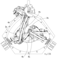
FIG. 13A shows the third embodiment's 3-view drawings for the orbit specification I with double crank sets.
FIG. 13B shows the third embodiment's 3-view drawings for the orbit specification I with double crank sets.
FIG. 13C shows the third embodiment's 3-view drawings for the orbit specification I with double crank sets.
FIG. 14A shows the fourth embodiment's 3-view drawings for the orbit specification II with double crank sets.
FIG. 14B shows the fourth embodiment's 3-view drawings for the orbit specification II with double crank sets.
FIG. 14C shows the fourth embodiment's 3-view drawings for the orbit specification II with double crank sets.
FIG. 15A shows the fifth embodiment's 3-view drawings for the orbit specification I without a crank set.
FIG. 15B shows the fifth embodiment's 3-view drawings for the orbit specification I without a crank set.
FIG. 15C shows the fifth embodiment's 3-view drawings for the orbit specification I without a crank set.
FIG. 16A shows the sixth embodiment's 3-view drawings for the orbit specification II without a crank set.
FIG. 16B shows the sixth embodiment's 3-view drawings for the orbit specification II without a crank set.
FIG. 16C shows the sixth embodiment's 3-view drawings for the orbit specification II without a crank set.
DETAILED DESCRIPTION OF THE EMBODIMENTS
In the embodiments, a mechanism may be manipulated for spherical coordinate kinematics and geometrically constituted by twelve axes. The mechanism comprises a base frame set, two terminal frame sets, four arc-link sets, at least one base driver sets, at least one terminal driver sets, and at most two crank sets.
The base frame set comprises a base frame 0 c including a plurality of brackets and four base rotating modules 0 a installed into the base frame 0 c. The base frame 0 c is configured with four vertices which can be used to constitute a base geometrical tetrahedron. Each unit vector Ui, wherein i=1-4, respectively corresponds to a vertex-to-center line of the base geometrical tetrahedron and these four vertex-to-center lines converge at the center of the base frame 0 c. An angle between any two vertex-to-center lines of the base geometrical tetrahedron is geometrically represented as Λij=ArcCos(Ui•Uj), wherein i≠j. The angle between any two vertex-to-center lines of the base geometrical tetrahedron is greater than 750 and less than 150°, i.e.: 75°<Λij<150°. The geometric definition of the base frame set is shown in FIG. 1A, FIG. 2A, FIG. 3A, and FIG. 4A.
According to the first patent (U.S. Pat. No. 8,579,714), if the base frame 0 c is geometrically defined as a regular tetrahedron, the regular tetrahedron frame may be easily designed and simulated due to its simple and symmetry. Thus, six angles defined by each pair of vertex-to-center lines of the base frame 0 c are equal, approximately 109.5°, i.e.: Λ12=Λ13=Λ14=Λ23=Λ24=Λ34≈109.5°. But the regular tetrahedron is a configuration most likely to have singularities. This characteristic was clearly introduced and analyzed in the first patent (U.S. Pat. No. 8,579,714). For the sake of avoiding singularities, it is preferred that the base frame 0 c is not defined as a regular tetrahedron.
Each base rotating module 0 a comprises an outer hollow shaft 0 a 1 and an inner hollow shaft 0 a 2. Both ends of the outer hollow shaft 0 a 1 are indicated as an active end and a passive end. Both ends of the inner hollow shaft 0 a 2 are indicated as an active end and a passive end. The outer hollow shaft 0 a 1 may pivotally rotate with the inner hollow shaft 0 a 2.
In the two terminal frame sets, each terminal frame set comprises a terminal frame 4 c and two terminal rotating modules 4 a installed into the terminal frame 4 c. The terminal frame 4 c is geometrically defined by two vertices which can be used to constitute a terminal geometrical arc. Each axis of each terminal rotating module 4 a respectively corresponds to a vertex-to-center line of the terminal geometrical arc and these vertex-to-center lines converge at the center of the base frame 0 c for concentrically rotating the terminal frame along a specified geometric orbit. The radius of the base frame's geometric orbit is denoted by r0, as shown in FIG. 1A and FIG. 2A. The radius of the terminal frame's geometric orbit is denoted by r4, as shown in FIG. 7A and FIG. 8A.
The two vertex-to-center lines of the first terminal geometrical arc are individually denoted by unit vector V1 and V2. An angle between the two vertex-to-center lines is geometrically represented as λ12=ArcCos(V1•V2). The two vertex-to-center lines of the second terminal geometrical arc are individually denoted by unit vector V3 and V4. An angle between the two vertex-to-center lines is geometrically represented as λ34=ArcCos(V3•V4). The angle between the two vertex-to-center lines of the terminal geometrical arc is greater than 750 and less than 150°, i.e.: 75°<λ12<150° and 75°<λ34<150°. The geometrical definitions of a terminal frame are shown in FIG. 5A, FIG. 6A, FIG. 7A, and FIG. 8A.
In the two terminal frame sets, each terminal frame set further comprises a terminal saddle 4 s which can be equipped onto the terminal frame's opposite side relative to terminal arc-links 2 c for carrying a payload. The terminal saddle 4 s may function as a lifting mechanism having an extendable piston rod as implemented in pneumatic cylinders, hydraulic cylinders, or an electric actuator. Applications may include a robot's shoulder joint and a robot's hip joint.
In the four arc-link sets, each arc-link set comprises a base arc-link 1 c, a terminal arc-link 2 c, an arc-link rotating module 2 a, a base timing pulley 2 p, a terminal timing pulley 2 q, a timing belt 2 b, and at least one pair of idler pulleys 2 z. Both ends of the base arc-link 1 c are indicated as a base end and a terminal end. Both ends of the terminal arc-link 2 c are indicated as a base end and a terminal end.
The base end of the base arc-link 1 c is pivotally rotated with the base end of the terminal arc-link 2 c via the arc-link rotating module 2 a. The base end of the base arc-link 1 c is pivotally fastened onto the passive end of the inner hollow shaft 0 a 2 of the base rotating module 0 a. The terminal end of the terminal arc-link 2 c is pivotally rotated with an axis of the terminal rotating module 4 a, each axis of arc-link rotating modules 2 a, denoted by unit vector Wi, wherein i=1-4, is normally directed into the center of the base frame 0 c for concentrically rotating each arc-link set along specified geometric orbit between the base frame 0 c and two terminal frames 4 c. The radius of each base arc-link's geometric orbit is denoted by r1. The radius of each terminal arc-link's geometric orbit is denoted by r2.
An arc-length of a base arc-link 1 c, geometrically represented by αi=ArcCos(Ui•Wi), is defined as an angle between two axes of the base rotating module 0 a and the arc-link rotating module 2 a which are individually connected with the same base arc-link 1 c. An arc-length of a terminal arc-link 2 c, geometrically represented by βi=ArcCos(Vi•Wi), is defined as an angle between two axes of terminal rotating module 4 a and the arc-link rotating module 2 a which are individually connected with the same terminal arc-link 2 c.
Referring to the first patent (U.S. Pat. No. 8,579,714), singularities avoidance and geometric limitation were clearly introduced and specifically analyzed. A sum of arc-lengths of any two of the base arc-links is greater than or equal to an angle between their corresponding vertex-to-center lines of the base geometrical tetrahedron, i.e.: Λij≤αi+αj, wherein i≠j. A sum of arc-lengths of any two of the terminal arc-links is greater than or equal to an angle between their corresponding vertex-to-center lines of the same terminal geometrical arc, i.e.: λ12≤β1+β2 and λ34≤β3+β4.
There may be a total of twelve axes in these four arc-link sets for pivoting with four base rotating modules 0 a, four arc-link rotating modules 2 a, and four terminal rotating modules 4 a individually. Therefore, the final output torque can be integrated via serial linking and parallel cooperating with the twelve rotating modules.
The same twelve-axis geometric configuration as the three listed patents may be used. An important issue is how to make a twelve-axis mechanism operate smoothly without mutual interference and/or singularity while contemplating practical design and regulating geometric limitation. Therefore, the invention is directed to a new approach regarding to interference and singularity avoidance compared to the first patent (U.S. Pat. No. 8,579,714).
After synthesizing the definition just mentioned above, two orbit specifications are classified.
Orbit specification I: The radius of the base frame's geometric orbit is “greater than” the radius of the terminal frame's geometric orbit, and the radius of each base arc-link's geometric orbit is “greater than” the radius of each terminal arc-link's geometric orbit, i.e.: r0>r1>r2>r4, shown as FIG. 7A-FIG. 7B.
Orbit specification II: The radius of the base frame's geometric orbit is “less than” the radius of the terminal frame's geometric orbit, and the radius of each base arc-link's geometric orbit is “less than” the radius of each terminal arc-link's geometric orbit, i.e.: r0<r1<r2<r4, shown as FIG. 8A-FIG. 8B.
The base timing pulley 2 p is pivotally fastened onto the active end of outer hollow shaft 0 a 1 of the base rotating module 0 a. The terminal timing pulley 2 q is pivotally fastened onto the base end of the terminal arc-link 2 c. All flanges of the at least one pair of idler pulleys 2 z are not able to exceed the outer flange of the base arc-link 1 c. The at least one pair of idler pulleys 2 z are installed onto both sides of the base arc-link 1 c individually.
Both ends of the timing belt 2 b are separately meshed and rotated with the base timing pulley 2 p and the terminal timing pulley 2 q. A direction and tension of the timing belt 2 b are functionally adjusted by the at least one pair of idler pulleys 2 z. The terminal timing pulley 2 q is synchronously rotated via the timing belt 2 b by the base timing pulley 2 p. See FIG. 3C, FIG. 4C, FIG. 4C, and FIG. 6C.
There may be at least one base driver set, wherein each base driver set comprises a base driving module 1 m, a base active gear 1 g and a base passive gear 1 h. The base active gear 1 g is fastened onto the output shaft of the base driving module 1 m. The base passive gear 1 h is pivotally fastened onto the passive end of the outer hollow shaft 0 a 1 of the base rotating module 0 a.
According to a pre-defined gear ratio, the base active gear 1 g and the base passive gear 1 h are selected to meet a design requirement. The distance between the shaft bores of the base active gear 1 g and the base passive gear 1 h is equal to a sum of reference radii of the base active gear 1 g and the base passive gear 1 h. The base passive gear 1 h meshed with the base active gear 1 g is synchronously rotated by the base driving module 1 m. The distance between shaft bores of the base active gear 1 g and the base passive gear 1 h can be zero. The base driving module 1 m is pivotally fastened onto the passive end of the outer hollow shaft 0 a 1 of the base rotating module 0 a. See FIG. 3B and FIG. 4B.
There may be at least one terminal driver set, wherein each terminal driver set comprises a terminal driving module 2 m, a terminal active gear 2 g, and a terminal passive gear 2 h. The terminal active gear 2 g is fastened onto the output shaft of the terminal driving module 2 m. The terminal passive gear 2 h is pivotally fastened onto the passive end of the inner hollow shaft 0 a 2 of the base rotating module 0 a.
According to a pre-defined gear ratio, the terminal active gear 2 g and the terminal passive gear 2 h are selected to meet a design requirement. The distance between the shaft bores of the terminal active gear 2 g and the terminal passive gear 2 h is equal to a sum of reference radii of the terminal active gear 2 g and the terminal passive gear 2 h. The terminal passive gear 2 h meshed with the terminal active gear 2 g is synchronously rotated by the terminal driving module 2 m. The distance between shaft bores of the terminal active gear 2 g and the terminal passive gear 2 h can be zero. The terminal driving module 2 m is pivotally fastened onto the passive end of the inner hollow shaft 0 a 2 of the base rotating module 0 a. See FIG. 5B and FIG. 6B.
In the at most two crank sets, each crank set comprises an arc crank 3 c and a crank rotating module 3 a. An end of the arc crank 3 c is mounted on a rod which is concentrically extended opposite side relative to the base frame 0 c, these extending lines of the extended rods are denoted by unit vector Ni, wherein i=1-2. The other end of the arc crank 3 c is pivoted through an axis of base rotating module 0 a and installed into the crank rotating module 3 a opposite side relative to the base frame 0 c, and the arc crank 3 c can be concentrically rotated along a geometric orbit between terminal arc-link 2 c and terminal frame 4 c.The radius of each arc crank's geometric orbit is denoted by r3. An arc-length of arc crank 3 c, geometrically represented by δi=ArcCos(Ui•Ni), wherein i=1-2, is defined as an angle between the axis of base rotating module 0 a and the extended rod mounted onto the same arc crank 3 c. The arc-length of arc crank 3 c is less than or equal to 90°, i.e.: δi≤90°, wherein i=1-2. The geometric definitions of a crank set are shown as FIG. 9A-FIG. 9B and FIG. 10A-FIG. 10B.
The crank rotating module 3 a can be functionally actuated for preventing predictable interference caused by terminal arc-link 2 c and/or terminal frame 4 c. Each crank set further comprises a crank saddle 3 s which can be equipped onto the arc crank's extended rod opposite side relative to the base frame 0 c for carrying the payload. The crank saddle 3 s can be a clamp of a lathe to support a shaft of a laser cutter or install a drill as applied in multi-shaft composite machining centers.
The end effect arc-link assembly introduced in the second patent (U.S. Pat. No. 9,579,786) is renamed as a crank set, and “at least one” end effect arc-link assemblies is renamed as “at most two” crank sets. Due to geometric configurations, no more than four crank sets may be installed in the base frame 0 c. After simulating and verifying, utility and effectiveness of greater than two crank sets are worthless, because they are unavoidably interfered with base frame 0 c and/or each arc-link set. Working space of two crank sets is also reduced but acceptable, because they can clamp the payload corporately and stably. A working space of one crank set may be gradually increased and a single crank hanging alone may produce oscillation and vibration.
While the first patent (U.S. Pat. No. 8,579,714) has a greater space for orientating due to no hinder of any crank set, it is capable of directly outputting torque due to eliminating crank set. Although there may be a shortage of crank saddles 3 s, a payload may still be carried on equipping terminal saddles 4 s. The different quantity of crank sets may be separately adapted in different suitable domains, therefore, the quantity about “at most two” is adapted in the invention to replace by the quantity about “at least one” in the second patent (U.S. Pat. No. 9,579,786). After analyzing geometrics and configurations, the sufficient and enable mode is disclosed as expected.
The base frame 0 c can be either a close-chain type or an open-chain type, and the close-chain type is configured to enhance rigidity to avoid vibration or deformation. The open-chain type is configured to prevent predictable interference caused by arc-link sets and/or crank sets.
The base rotating module 0 a can be assembled by a torque output device and/or an angle sensor and/or a bearing with a shaft. The arc-link rotating module 2 a can be assembled by a torque output device and/or an angle sensor and/or a bearing with a shaft. The terminal rotating module 4 a can be assembled by a torque output device and/or an angle sensor and/or a bearing with a shaft. The crank rotating module 3 a can be assembled by a torque output device and/or an angle sensor and/or a bearing with a shaft.
There are six embodiments.
The first embodiment is the orbit specification I with a single crank set, shown as FIG. 11A-FIG. 11C.
The second embodiment is the orbit specification II with a single crank set, shown as FIG. 12A-FIG. 12C.
The third embodiment is the orbit specification I with double crank sets, shown as FIG. 13A-FIG. 13C.
The fourth embodiment is the orbit specification II with double crank sets, shown as FIG. 14A-FIG. 14C.
The fifth embodiment is the orbit specification I without a crank set, shown as FIG. 15A-FIG. 15C.
The sixth embodiment is the orbit specification II without a crank set, shown as FIG. 16A-FIG. 16C.
Those skilled in the art will readily observe that numerous modifications and alterations of the device and method may be made. Accordingly, the above disclosure should be construed as limited only by the metes and bounds of the appended claims.