US11904465B2 - Spherical coordinate orientating mechanism - Google Patents
Spherical coordinate orientating mechanism Download PDFInfo
- Publication number
- US11904465B2 US11904465B2 US17/517,965 US202117517965A US11904465B2 US 11904465 B2 US11904465 B2 US 11904465B2 US 202117517965 A US202117517965 A US 202117517965A US 11904465 B2 US11904465 B2 US 11904465B2
- Authority
- US
- United States
- Prior art keywords
- terminal
- base
- arc
- link
- gear
- Prior art date
- Legal status (The legal status is an assumption and is not a legal conclusion. Google has not performed a legal analysis and makes no representation as to the accuracy of the status listed.)
- Active, expires
Links
- 230000007246 mechanism Effects 0.000 title claims abstract description 25
- 239000002131 composite material Substances 0.000 abstract description 3
- 210000004394 hip joint Anatomy 0.000 abstract description 3
- 210000000323 shoulder joint Anatomy 0.000 abstract description 3
- 230000005540 biological transmission Effects 0.000 abstract description 2
- 238000001514 detection method Methods 0.000 abstract description 2
- 230000000694 effects Effects 0.000 description 2
- 238000000034 method Methods 0.000 description 2
- 230000001105 regulatory effect Effects 0.000 description 2
- 230000004075 alteration Effects 0.000 description 1
- 230000000712 assembly Effects 0.000 description 1
- 238000000429 assembly Methods 0.000 description 1
- 230000008859 change Effects 0.000 description 1
- 238000003754 machining Methods 0.000 description 1
- 238000012986 modification Methods 0.000 description 1
- 230000004048 modification Effects 0.000 description 1
- 230000010355 oscillation Effects 0.000 description 1
- 230000002194 synthesizing effect Effects 0.000 description 1
Images


Classifications
-
- B—PERFORMING OPERATIONS; TRANSPORTING
- B25—HAND TOOLS; PORTABLE POWER-DRIVEN TOOLS; MANIPULATORS
- B25J—MANIPULATORS; CHAMBERS PROVIDED WITH MANIPULATION DEVICES
- B25J17/00—Joints
-
- B—PERFORMING OPERATIONS; TRANSPORTING
- B25—HAND TOOLS; PORTABLE POWER-DRIVEN TOOLS; MANIPULATORS
- B25J—MANIPULATORS; CHAMBERS PROVIDED WITH MANIPULATION DEVICES
- B25J9/00—Programme-controlled manipulators
- B25J9/02—Programme-controlled manipulators characterised by movement of the arms, e.g. cartesian coordinate type
- B25J9/04—Programme-controlled manipulators characterised by movement of the arms, e.g. cartesian coordinate type by rotating at least one arm, excluding the head movement itself, e.g. cylindrical coordinate type or polar coordinate type
- B25J9/045—Polar coordinate type
-
- B—PERFORMING OPERATIONS; TRANSPORTING
- B25—HAND TOOLS; PORTABLE POWER-DRIVEN TOOLS; MANIPULATORS
- B25J—MANIPULATORS; CHAMBERS PROVIDED WITH MANIPULATION DEVICES
- B25J13/00—Controls for manipulators
- B25J13/08—Controls for manipulators by means of sensing devices, e.g. viewing or touching devices
- B25J13/088—Controls for manipulators by means of sensing devices, e.g. viewing or touching devices with position, velocity or acceleration sensors
-
- B—PERFORMING OPERATIONS; TRANSPORTING
- B25—HAND TOOLS; PORTABLE POWER-DRIVEN TOOLS; MANIPULATORS
- B25J—MANIPULATORS; CHAMBERS PROVIDED WITH MANIPULATION DEVICES
- B25J18/00—Arms
- B25J18/007—Arms the end effector rotating around a fixed point
-
- B—PERFORMING OPERATIONS; TRANSPORTING
- B25—HAND TOOLS; PORTABLE POWER-DRIVEN TOOLS; MANIPULATORS
- B25J—MANIPULATORS; CHAMBERS PROVIDED WITH MANIPULATION DEVICES
- B25J19/00—Accessories fitted to manipulators, e.g. for monitoring, for viewing; Safety devices combined with or specially adapted for use in connection with manipulators
-
- B—PERFORMING OPERATIONS; TRANSPORTING
- B25—HAND TOOLS; PORTABLE POWER-DRIVEN TOOLS; MANIPULATORS
- B25J—MANIPULATORS; CHAMBERS PROVIDED WITH MANIPULATION DEVICES
- B25J9/00—Programme-controlled manipulators
- B25J9/003—Programme-controlled manipulators having parallel kinematics
- B25J9/0045—Programme-controlled manipulators having parallel kinematics with kinematics chains having a rotary joint at the base
- B25J9/0048—Programme-controlled manipulators having parallel kinematics with kinematics chains having a rotary joint at the base with kinematics chains of the type rotary-rotary-rotary
-
- B—PERFORMING OPERATIONS; TRANSPORTING
- B25—HAND TOOLS; PORTABLE POWER-DRIVEN TOOLS; MANIPULATORS
- B25J—MANIPULATORS; CHAMBERS PROVIDED WITH MANIPULATION DEVICES
- B25J9/00—Programme-controlled manipulators
- B25J9/10—Programme-controlled manipulators characterised by positioning means for manipulator elements
- B25J9/102—Gears specially adapted therefor, e.g. reduction gears
-
- B—PERFORMING OPERATIONS; TRANSPORTING
- B25—HAND TOOLS; PORTABLE POWER-DRIVEN TOOLS; MANIPULATORS
- B25J—MANIPULATORS; CHAMBERS PROVIDED WITH MANIPULATION DEVICES
- B25J9/00—Programme-controlled manipulators
- B25J9/10—Programme-controlled manipulators characterised by positioning means for manipulator elements
- B25J9/104—Programme-controlled manipulators characterised by positioning means for manipulator elements with cables, chains or ribbons
-
- B—PERFORMING OPERATIONS; TRANSPORTING
- B25—HAND TOOLS; PORTABLE POWER-DRIVEN TOOLS; MANIPULATORS
- B25J—MANIPULATORS; CHAMBERS PROVIDED WITH MANIPULATION DEVICES
- B25J9/00—Programme-controlled manipulators
- B25J9/10—Programme-controlled manipulators characterised by positioning means for manipulator elements
- B25J9/108—Bearings specially adapted therefor
-
- G—PHYSICS
- G01—MEASURING; TESTING
- G01B—MEASURING LENGTH, THICKNESS OR SIMILAR LINEAR DIMENSIONS; MEASURING ANGLES; MEASURING AREAS; MEASURING IRREGULARITIES OF SURFACES OR CONTOURS
- G01B21/00—Measuring arrangements or details thereof, where the measuring technique is not covered by the other groups of this subclass, unspecified or not relevant
Definitions
- a mechanism geometrically constituted with twelve axes can be manipulated for spherical coordinate kinematics.
- the invention can be applied to a multi-axis composite machining center machine or a multi-time element detection measuring shoulder joints of robots or hip joints of robots.
- the embodiments may be directed to a geometric configuration shown in three related patents: a first patent (U.S. Pat. No. 8,579,714), a second patent (U.S. Pat. No. 9,579,786, EP2863102, CN104511904), and a third patent (U.S. Pat. No. 9,851,045, EP3196532, CN107030682).
- One of the two geometric tetrahedron frames may be decoupled and reconstructed as two separated terminal frames which are constituted by two individual geometric arcs.
- the other geometric tetrahedron frame may not change its original geometric definition.
- a twelve-axis mechanism includes a base frame, two terminal frame sets, four arc-link sets, at least one base driver sets, at least one terminal driver sets, and at most two crank sets.
- the final output torque can be integrated via serial linking and parallel cooperating with the twelve rotating modules.
- crank sets are meaningful. It should be emphasized that the quantity of the crank sets can be optional, that is zero, one, or two.
- Claim 1 substantially includes a base frame set, two terminal frame sets, four arc-link sets, at least one base driver sets, at least one terminal driver sets, and at most two crank sets.
- Claim 8 substantially includes a base frame set, two terminal frame sets, four arc-link sets, at least one base driver sets, and at least one terminal driver sets. Except excluding crank sets, definitions and/or methods of all the other subsystems of claim 8 are same as those of claim 1 .
- FIG. 1 A shows geometrical and perspective drawings of base frame design type I.
- FIG. 1 B shows geometrical and perspective drawings of base frame design type I.
- FIG. 2 A shows geometrical and perspective drawings of base frame design type II.
- FIG. 2 B shows geometrical and perspective drawings of base frame design type II.
- FIG. 3 A shows geometrical and perspective drawings of base frame design type I.
- FIG. 3 B shows geometrical and perspective drawings of base frame design type I.
- FIG. 3 C shows geometrical and perspective drawings of base frame design type I.
- FIG. 4 A shows geometrical and perspective drawings of base frame design type II.
- FIG. 4 B shows geometrical and perspective drawings of base frame design type II.
- FIG. 4 C shows geometrical and perspective drawings of base frame design type II.
- FIG. 5 A shows geometrical and perspective drawings of the orbit specification I
- FIG. 5 B shows geometrical and perspective drawings of the orbit specification I
- FIG. 5 C shows geometrical and perspective drawings of the orbit specification I
- FIG. 6 A shows geometrical and perspective drawings of the orbit specification II.
- FIG. 6 B shows geometrical and perspective drawings of the orbit specification II.
- FIG. 6 C shows geometrical and perspective drawings of the orbit specification II.
- FIG. 7 A shows geometrical and perspective drawings of the orbit specification I.
- FIG. 7 B shows geometrical and perspective drawings of the orbit specification I.
- FIG. 8 A shows geometrical and perspective drawings of the orbit specification II.
- FIG. 8 B shows geometrical and perspective drawings of the orbit specification.
- FIG. 9 A shows geometrical and perspective drawings of a crank's pivotal configuration I.
- FIG. 9 B shows geometrical and perspective drawings of a crank's pivotal configuration I.
- FIG. 10 A shows geometrical and perspective drawings of a crank's pivotal configuration II.
- FIG. 10 B shows geometrical and perspective drawings of a crank's pivotal configuration II.
- FIG. 11 A shows the first embodiment's 3-view drawings for the orbit specification I with a single crank set.
- FIG. 11 B shows the first embodiment's 3-view drawings for the orbit specification I with a single crank set.
- FIG. 11 C shows the first embodiment's 3-view drawings for the orbit specification I with a single crank set.
- FIG. 12 A shows the second embodiment's 3-view drawings for the orbit specification II with a single crank set.
- FIG. 12 B shows the second embodiment's 3-view drawings for the orbit specification II with a single crank set.
- FIG. 12 C shows the second embodiment's 3-view drawings for the orbit specification II with a single crank set.
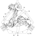
- FIG. 13 A shows the third embodiment's 3-view drawings for the orbit specification I with double crank sets.
- FIG. 13 B shows the third embodiment's 3-view drawings for the orbit specification I with double crank sets.
- FIG. 13 C shows the third embodiment's 3-view drawings for the orbit specification I with double crank sets.
- FIG. 14 A shows the fourth embodiment's 3-view drawings for the orbit specification II with double crank sets.
- FIG. 14 B shows the fourth embodiment's 3-view drawings for the orbit specification II with double crank sets.
- FIG. 14 C shows the fourth embodiment's 3-view drawings for the orbit specification II with double crank sets.
- FIG. 15 A shows the fifth embodiment's 3-view drawings for the orbit specification I without a crank set.
- FIG. 15 B shows the fifth embodiment's 3-view drawings for the orbit specification I without a crank set.
- FIG. 15 C shows the fifth embodiment's 3-view drawings for the orbit specification I without a crank set.
- FIG. 16 A shows the sixth embodiment's 3-view drawings for the orbit specification II without a crank set.
- FIG. 16 B shows the sixth embodiment's 3-view drawings for the orbit specification II without a crank set.
- FIG. 16 C shows the sixth embodiment's 3-view drawings for the orbit specification II without a crank set.
- a mechanism may be manipulated for spherical coordinate kinematics and geometrically constituted by twelve axes.
- the mechanism comprises a base frame set, two terminal frame sets, four arc-link sets, at least one base driver sets, at least one terminal driver sets, and at most two crank sets.
- the base frame set comprises a base frame 0 c including a plurality of brackets and four base rotating modules 0 a installed into the base frame 0 c .
- the base frame 0 c is configured with four vertices which can be used to constitute a base geometrical tetrahedron.
- the angle between any two vertex-to-center lines of the base geometrical tetrahedron is greater than 750 and less than 150°, i.e.: 75° ⁇ ij ⁇ 150°.
- the geometric definition of the base frame set is shown in FIG. 1 A , FIG. 2 A , FIG. 3 A , and FIG. 4 A .
- the base frame 0 c is geometrically defined as a regular tetrahedron
- the regular tetrahedron frame may be easily designed and simulated due to its simple and symmetry.
- the regular tetrahedron is a configuration most likely to have singularities. This characteristic was clearly introduced and analyzed in the first patent (U.S. Pat. No. 8,579,714).
- the base frame 0 c is not defined as a regular tetrahedron.
- Each base rotating module 0 a comprises an outer hollow shaft 0 a 1 and an inner hollow shaft 0 a 2 . Both ends of the outer hollow shaft 0 a 1 are indicated as an active end and a passive end. Both ends of the inner hollow shaft 0 a 2 are indicated as an active end and a passive end. The outer hollow shaft 0 a 1 may pivotally rotate with the inner hollow shaft 0 a 2 .
- each terminal frame set comprises a terminal frame 4 c and two terminal rotating modules 4 a installed into the terminal frame 4 c .
- the terminal frame 4 c is geometrically defined by two vertices which can be used to constitute a terminal geometrical arc.
- Each axis of each terminal rotating module 4 a respectively corresponds to a vertex-to-center line of the terminal geometrical arc and these vertex-to-center lines converge at the center of the base frame 0 c for concentrically rotating the terminal frame along a specified geometric orbit.
- the radius of the base frame's geometric orbit is denoted by r 0 , as shown in FIG. 1 A and FIG. 2 A .
- the radius of the terminal frame's geometric orbit is denoted by r 4 , as shown in FIG. 7 A and FIG. 8 A .
- the two vertex-to-center lines of the first terminal geometrical arc are individually denoted by unit vector V 1 and V 2 .
- the two vertex-to-center lines of the second terminal geometrical arc are individually denoted by unit vector V 3 and V 4 .
- the angle between the two vertex-to-center lines of the terminal geometrical arc is greater than 750 and less than 150°, i.e.: 75° ⁇ 12 ⁇ 150° and 75° ⁇ 34 ⁇ 150°.
- the geometrical definitions of a terminal frame are shown in FIG. 5 A , FIG. 6 A , FIG. 7 A , and FIG. 8 A .
- each terminal frame set further comprises a terminal saddle 4 s which can be equipped onto the terminal frame's opposite side relative to terminal arc-links 2 c for carrying a payload.
- the terminal saddle 4 s may function as a lifting mechanism having an extendable piston rod as implemented in pneumatic cylinders, hydraulic cylinders, or an electric actuator. Applications may include a robot's shoulder joint and a robot's hip joint.
- each arc-link set comprises a base arc-link 1 c , a terminal arc-link 2 c , an arc-link rotating module 2 a , a base timing pulley 2 p , a terminal timing pulley 2 q , a timing belt 2 b , and at least one pair of idler pulleys 2 z .
- Both ends of the base arc-link 1 c are indicated as a base end and a terminal end.
- Both ends of the terminal arc-link 2 c are indicated as a base end and a terminal end.
- the base end of the base arc-link 1 c is pivotally rotated with the base end of the terminal arc-link 2 c via the arc-link rotating module 2 a .
- the base end of the base arc-link 1 c is pivotally fastened onto the passive end of the inner hollow shaft 0 a 2 of the base rotating module 0 a .
- the radius of each base arc-link's geometric orbit is denoted by r 1 .
- the radius of each terminal arc-link's geometric orbit is denoted by r 2 .
- a sum of arc-lengths of any two of the base arc-links is greater than or equal to an angle between their corresponding vertex-to-center lines of the base geometrical tetrahedron, i.e.: ⁇ ij ⁇ i + ⁇ j , wherein i ⁇ j.
- a sum of arc-lengths of any two of the terminal arc-links is greater than or equal to an angle between their corresponding vertex-to-center lines of the same terminal geometrical arc, i.e.: ⁇ 12 ⁇ 1 + ⁇ 2 and ⁇ 34 ⁇ 3 + ⁇ 4 .
- Orbit specification I The radius of the base frame's geometric orbit is “greater than” the radius of the terminal frame's geometric orbit, and the radius of each base arc-link's geometric orbit is “greater than” the radius of each terminal arc-link's geometric orbit, i.e.: r 0 >r 1 >r 2 >r 4 , shown as FIG. 7 A - FIG. 7 B .
- Orbit specification II The radius of the base frame's geometric orbit is “less than” the radius of the terminal frame's geometric orbit, and the radius of each base arc-link's geometric orbit is “less than” the radius of each terminal arc-link's geometric orbit, i.e.: r 0 ⁇ r 1 ⁇ r 2 ⁇ r 4 , shown as FIG. 8 A - FIG. 8 B .
- the base timing pulley 2 p is pivotally fastened onto the active end of outer hollow shaft 0 a 1 of the base rotating module 0 a .
- the terminal timing pulley 2 q is pivotally fastened onto the base end of the terminal arc-link 2 c . All flanges of the at least one pair of idler pulleys 2 z are not able to exceed the outer flange of the base arc-link 1 c .
- the at least one pair of idler pulleys 2 z are installed onto both sides of the base arc-link 1 c individually.
- Both ends of the timing belt 2 b are separately meshed and rotated with the base timing pulley 2 p and the terminal timing pulley 2 q .
- a direction and tension of the timing belt 2 b are functionally adjusted by the at least one pair of idler pulleys 2 z .
- the terminal timing pulley 2 q is synchronously rotated via the timing belt 2 b by the base timing pulley 2 p . See FIG. 3 C , FIG. 4 C , FIG. 4 C , and FIG. 6 C .
- each base driver set comprises a base driving module 1 m , a base active gear 1 g and a base passive gear 1 h .
- the base active gear 1 g is fastened onto the output shaft of the base driving module 1 m .
- the base passive gear 1 h is pivotally fastened onto the passive end of the outer hollow shaft 0 a 1 of the base rotating module 0 a.
- the base active gear 1 g and the base passive gear 1 h are selected to meet a design requirement.
- the distance between the shaft bores of the base active gear 1 g and the base passive gear 1 h is equal to a sum of reference radii of the base active gear 1 g and the base passive gear 1 h .
- the base passive gear 1 h meshed with the base active gear 1 g is synchronously rotated by the base driving module 1 m .
- the distance between shaft bores of the base active gear 1 g and the base passive gear 1 h can be zero.
- the base driving module 1 m is pivotally fastened onto the passive end of the outer hollow shaft 0 a 1 of the base rotating module 0 a . See FIG. 3 B and FIG. 4 B .
- each terminal driver set comprises a terminal driving module 2 m , a terminal active gear 2 g , and a terminal passive gear 2 h .
- the terminal active gear 2 g is fastened onto the output shaft of the terminal driving module 2 m .
- the terminal passive gear 2 h is pivotally fastened onto the passive end of the inner hollow shaft 0 a 2 of the base rotating module 0 a.
- the terminal active gear 2 g and the terminal passive gear 2 h are selected to meet a design requirement.
- the distance between the shaft bores of the terminal active gear 2 g and the terminal passive gear 2 h is equal to a sum of reference radii of the terminal active gear 2 g and the terminal passive gear 2 h .
- the terminal passive gear 2 h meshed with the terminal active gear 2 g is synchronously rotated by the terminal driving module 2 m .
- the distance between shaft bores of the terminal active gear 2 g and the terminal passive gear 2 h can be zero.
- the terminal driving module 2 m is pivotally fastened onto the passive end of the inner hollow shaft 0 a 2 of the base rotating module 0 a . See FIG. 5 B and FIG. 6 B .
- each crank set comprises an arc crank 3 c and a crank rotating module 3 a .
- the other end of the arc crank 3 c is pivoted through an axis of base rotating module 0 a and installed into the crank rotating module 3 a opposite side relative to the base frame 0 c , and the arc crank 3 c can be concentrically rotated along a geometric orbit between terminal arc-link 2 c and terminal frame 4 c .
- the radius of each arc crank's geometric orbit is denoted by r 3 .
- the geometric definitions of a crank set are shown as FIG. 9 A - FIG. 9 B and FIG. 10 A - FIG. 10 B .
- the crank rotating module 3 a can be functionally actuated for preventing predictable interference caused by terminal arc-link 2 c and/or terminal frame 4 c .
- Each crank set further comprises a crank saddle 3 s which can be equipped onto the arc crank's extended rod opposite side relative to the base frame 0 c for carrying the payload.
- the crank saddle 3 s can be a clamp of a lathe to support a shaft of a laser cutter or install a drill as applied in multi-shaft composite machining centers.
- crank set The end effect arc-link assembly introduced in the second patent (U.S. Pat. No. 9,579,786) is renamed as a crank set, and “at least one” end effect arc-link assemblies is renamed as “at most two” crank sets. Due to geometric configurations, no more than four crank sets may be installed in the base frame 0 c . After simulating and verifying, utility and effectiveness of greater than two crank sets are worthless, because they are unavoidably interfered with base frame 0 c and/or each arc-link set. Working space of two crank sets is also reduced but acceptable, because they can clamp the payload corporately and stably. A working space of one crank set may be gradually increased and a single crank hanging alone may produce oscillation and vibration.
- While the first patent (U.S. Pat. No. 8,579,714) has a greater space for orientating due to no hinder of any crank set, it is capable of directly outputting torque due to eliminating crank set. Although there may be a shortage of crank saddles 3 s , a payload may still be carried on equipping terminal saddles 4 s .
- the different quantity of crank sets may be separately adapted in different suitable domains, therefore, the quantity about “at most two” is adapted in the invention to replace by the quantity about “at least one” in the second patent (U.S. Pat. No. 9,579,786). After analyzing geometrics and configurations, the sufficient and enable mode is disclosed as expected.
- the base frame 0 c can be either a close-chain type or an open-chain type, and the close-chain type is configured to enhance rigidity to avoid vibration or deformation.
- the open-chain type is configured to prevent predictable interference caused by arc-link sets and/or crank sets.
- the base rotating module 0 a can be assembled by a torque output device and/or an angle sensor and/or a bearing with a shaft.
- the arc-link rotating module 2 a can be assembled by a torque output device and/or an angle sensor and/or a bearing with a shaft.
- the terminal rotating module 4 a can be assembled by a torque output device and/or an angle sensor and/or a bearing with a shaft.
- the crank rotating module 3 a can be assembled by a torque output device and/or an angle sensor and/or a bearing with a shaft.
- the first embodiment is the orbit specification I with a single crank set, shown as FIG. 11 A - FIG. 11 C .
- the second embodiment is the orbit specification II with a single crank set, shown as FIG. 12 A - FIG. 12 C .
- the third embodiment is the orbit specification I with double crank sets, shown as FIG. 13 A- FIG. 13 C .
- the fourth embodiment is the orbit specification II with double crank sets, shown as FIG. 14 A - FIG. 14 C .
- the fifth embodiment is the orbit specification I without a crank set, shown as FIG. 15 A - FIG. 15 C .
- the sixth embodiment is the orbit specification II without a crank set, shown as FIG. 16 A - FIG. 16 C .
Landscapes
- Engineering & Computer Science (AREA)
- Robotics (AREA)
- Mechanical Engineering (AREA)
- Human Computer Interaction (AREA)
- Physics & Mathematics (AREA)
- General Physics & Mathematics (AREA)
- Transmission Devices (AREA)
Abstract
Description
Claims (13)
Applications Claiming Priority (2)
| Application Number | Priority Date | Filing Date | Title |
|---|---|---|---|
| TW109138311A TW202219420A (en) | 2020-11-03 | 2020-11-03 | Spherical coordinate orientating mechanism |
| TW109138311 | 2020-11-03 |
Publications (2)
| Publication Number | Publication Date |
|---|---|
| US20220134538A1 US20220134538A1 (en) | 2022-05-05 |
| US11904465B2 true US11904465B2 (en) | 2024-02-20 |
Family
ID=81362809
Family Applications (1)
| Application Number | Title | Priority Date | Filing Date |
|---|---|---|---|
| US17/517,965 Active 2041-12-12 US11904465B2 (en) | 2020-11-03 | 2021-11-03 | Spherical coordinate orientating mechanism |
Country Status (3)
| Country | Link |
|---|---|
| US (1) | US11904465B2 (en) |
| CN (1) | CN114434486A (en) |
| TW (1) | TW202219420A (en) |
Families Citing this family (3)
| Publication number | Priority date | Publication date | Assignee | Title |
|---|---|---|---|---|
| CN112888878A (en) * | 2018-10-10 | 2021-06-01 | 国立大学法人九州工业大学 | Parallel linkage and linkage actuating device |
| JP7222447B1 (en) * | 2021-09-21 | 2023-02-15 | 日本精工株式会社 | Parallel link mechanism |
| CN114872012B (en) * | 2022-07-12 | 2022-09-09 | 国网辽宁省电力有限公司 | Telescopic multifunctional high-altitude operation manipulator |
Citations (9)
| Publication number | Priority date | Publication date | Assignee | Title |
|---|---|---|---|---|
| US5342244A (en) * | 1993-01-08 | 1994-08-30 | Nelson Kevin R | Human-powered gyroscope |
| US6026703A (en) * | 1997-08-14 | 2000-02-22 | Stanisic; Michael M. | Dexterous split equator joint |
| US20100043577A1 (en) * | 2008-06-04 | 2010-02-25 | Ross-Hime Designs, Inc. | Robotic manipulator |
| US7735385B2 (en) * | 2007-08-09 | 2010-06-15 | The United States Of America As Represented By The Administrator Of The National Aeronautics And Space Administration | Joint assembly |
| US20110207106A1 (en) * | 2008-10-14 | 2011-08-25 | Francisco Pacheco | Teaching apparatus |
| US8579714B2 (en) * | 2010-10-04 | 2013-11-12 | Trui, Wen-Der | Space orientating mechanism with two tetrahedrons and eight arc-links |
| US9579786B2 (en) * | 2013-09-26 | 2017-02-28 | Wen-Der TRUI | Spherical coordinates manipulating mechanism |
| US9851045B2 (en) * | 2016-01-15 | 2017-12-26 | Wen-Der TRUI | Twelve axes mechanism for spherical coordinate kinematics |
| KR20180083246A (en) * | 2017-01-12 | 2018-07-20 | 한국전자통신연구원 | Balance arm apparatus for supporting heavy tools |
-
2020
- 2020-11-03 TW TW109138311A patent/TW202219420A/en unknown
-
2021
- 2021-11-02 CN CN202111286636.3A patent/CN114434486A/en active Pending
- 2021-11-03 US US17/517,965 patent/US11904465B2/en active Active
Patent Citations (9)
| Publication number | Priority date | Publication date | Assignee | Title |
|---|---|---|---|---|
| US5342244A (en) * | 1993-01-08 | 1994-08-30 | Nelson Kevin R | Human-powered gyroscope |
| US6026703A (en) * | 1997-08-14 | 2000-02-22 | Stanisic; Michael M. | Dexterous split equator joint |
| US7735385B2 (en) * | 2007-08-09 | 2010-06-15 | The United States Of America As Represented By The Administrator Of The National Aeronautics And Space Administration | Joint assembly |
| US20100043577A1 (en) * | 2008-06-04 | 2010-02-25 | Ross-Hime Designs, Inc. | Robotic manipulator |
| US20110207106A1 (en) * | 2008-10-14 | 2011-08-25 | Francisco Pacheco | Teaching apparatus |
| US8579714B2 (en) * | 2010-10-04 | 2013-11-12 | Trui, Wen-Der | Space orientating mechanism with two tetrahedrons and eight arc-links |
| US9579786B2 (en) * | 2013-09-26 | 2017-02-28 | Wen-Der TRUI | Spherical coordinates manipulating mechanism |
| US9851045B2 (en) * | 2016-01-15 | 2017-12-26 | Wen-Der TRUI | Twelve axes mechanism for spherical coordinate kinematics |
| KR20180083246A (en) * | 2017-01-12 | 2018-07-20 | 한국전자통신연구원 | Balance arm apparatus for supporting heavy tools |
Also Published As
| Publication number | Publication date |
|---|---|
| US20220134538A1 (en) | 2022-05-05 |
| TW202219420A (en) | 2022-05-16 |
| CN114434486A (en) | 2022-05-06 |
Similar Documents
| Publication | Publication Date | Title |
|---|---|---|
| US11904465B2 (en) | Spherical coordinate orientating mechanism | |
| KR20120127888A (en) | Weight compensation mechanism and robot arm using the same | |
| Endo et al. | A passive weight compensation mechanism with a non-circular pulley and a spring | |
| Di Gregorio | A new family of spherical parallel manipulators | |
| US9851045B2 (en) | Twelve axes mechanism for spherical coordinate kinematics | |
| Jean et al. | Static balancing of planar parallel manipulators | |
| Lijin et al. | Design of a novel robotic arm with non-backlash driving for friction stir welding process | |
| Petrescu et al. | Some aspects of the structure of planar mechanisms | |
| CN107030682B (en) | Twelve-axis spherical coordinate movement mechanism | |
| JP2016505396A (en) | Pure translational serial manipulator robot with space-saving three degrees of freedom | |
| CN106040896A (en) | Series-parallel hybrid stamping feeding-discharging manipulator | |
| CN104552247A (en) | Hybrid robot mechanism with three degrees of freedom | |
| Jin et al. | Structure synthesis and singularity analysis of a parallel manipulator based on selective actuation | |
| Huang et al. | A new closed-form kinematics of the generalized 3-DOF spherical parallel manipulator | |
| Huda et al. | Kinematic analysis and synthesis of a 3-URU pure rotational parallel mechanism with respect to singularity and workspace | |
| Leguay-Durand et al. | Design of a 3-dof parallel translating manipulator with upu joints kinematic chains | |
| CN106903672A (en) | Two branch's Three Degree Of Freedom industrial robots | |
| CN108582152B (en) | Joint mechanism with three degrees of freedom and capable of rotating at fixed point | |
| KR20160148193A (en) | Articulated robot with Axis inoperative certain setting | |
| Ruiz-Torres et al. | Design and analysis of CICABOT: a novel translational parallel manipulator based on two 5-bar mechanisms | |
| Fan et al. | A novel 2T2R 4-DOF parallel manipulator | |
| Martini et al. | Static balancing of a parallel kinematics machine with Linear-Delta architecture | |
| Hess-Coelho et al. | Workspace optimization of 3 RSS+ CP parallel mechanisms | |
| CN213292823U (en) | Boxing manipulator with rotation function | |
| JP7260987B2 (en) | Dual-arm work device |
Legal Events
| Date | Code | Title | Description |
|---|---|---|---|
| FEPP | Fee payment procedure |
Free format text: ENTITY STATUS SET TO UNDISCOUNTED (ORIGINAL EVENT CODE: BIG.); ENTITY STATUS OF PATENT OWNER: SMALL ENTITY |
|
| AS | Assignment |
Owner name: TRUI, WEN-DER, TAIWAN Free format text: ASSIGNMENT OF ASSIGNORS INTEREST;ASSIGNOR:LIN, SHU-CHING;REEL/FRAME:058014/0048 Effective date: 20211028 |
|
| FEPP | Fee payment procedure |
Free format text: ENTITY STATUS SET TO SMALL (ORIGINAL EVENT CODE: SMAL); ENTITY STATUS OF PATENT OWNER: SMALL ENTITY |
|
| STPP | Information on status: patent application and granting procedure in general |
Free format text: DOCKETED NEW CASE - READY FOR EXAMINATION |
|
| STPP | Information on status: patent application and granting procedure in general |
Free format text: NON FINAL ACTION MAILED |
|
| STPP | Information on status: patent application and granting procedure in general |
Free format text: RESPONSE TO NON-FINAL OFFICE ACTION ENTERED AND FORWARDED TO EXAMINER |
|
| STPP | Information on status: patent application and granting procedure in general |
Free format text: NOTICE OF ALLOWANCE MAILED -- APPLICATION RECEIVED IN OFFICE OF PUBLICATIONS |
|
| STPP | Information on status: patent application and granting procedure in general |
Free format text: PUBLICATIONS -- ISSUE FEE PAYMENT VERIFIED |
|
| STCF | Information on status: patent grant |
Free format text: PATENTED CASE |