US11904448B2 - Hand-held power tool - Google Patents
Hand-held power tool Download PDFInfo
- Publication number
- US11904448B2 US11904448B2 US17/760,675 US202017760675A US11904448B2 US 11904448 B2 US11904448 B2 US 11904448B2 US 202017760675 A US202017760675 A US 202017760675A US 11904448 B2 US11904448 B2 US 11904448B2
- Authority
- US
- United States
- Prior art keywords
- piston
- pressing force
- electric motor
- impact
- acceleration
- Prior art date
- Legal status (The legal status is an assumption and is not a legal conclusion. Google has not performed a legal analysis and makes no representation as to the accuracy of the status listed.)
- Active
Links
- 230000001133 acceleration Effects 0.000 claims abstract description 38
- 230000007246 mechanism Effects 0.000 claims abstract description 29
- 238000000034 method Methods 0.000 claims abstract description 6
- 238000011156 evaluation Methods 0.000 claims description 5
- 230000001105 regulatory effect Effects 0.000 claims description 3
- 230000008878 coupling Effects 0.000 claims description 2
- 238000010168 coupling process Methods 0.000 claims description 2
- 238000005859 coupling reaction Methods 0.000 claims description 2
- 230000004044 response Effects 0.000 claims description 2
- 230000001276 controlling effect Effects 0.000 claims 1
- 238000009423 ventilation Methods 0.000 description 12
- 239000000758 substrate Substances 0.000 description 6
- 230000006835 compression Effects 0.000 description 4
- 238000007906 compression Methods 0.000 description 4
- 230000000737 periodic effect Effects 0.000 description 4
- 230000005540 biological transmission Effects 0.000 description 3
- 230000006378 damage Effects 0.000 description 2
- 238000013016 damping Methods 0.000 description 2
- 230000009471 action Effects 0.000 description 1
- 230000008901 benefit Effects 0.000 description 1
- 238000006243 chemical reaction Methods 0.000 description 1
- 230000001419 dependent effect Effects 0.000 description 1
- 238000013461 design Methods 0.000 description 1
- 230000006870 function Effects 0.000 description 1
- 230000005484 gravity Effects 0.000 description 1
- 230000003287 optical effect Effects 0.000 description 1
- 230000008569 process Effects 0.000 description 1
- 238000012545 processing Methods 0.000 description 1
- 230000009467 reduction Effects 0.000 description 1
- 230000003252 repetitive effect Effects 0.000 description 1
- 239000007787 solid Substances 0.000 description 1
- 230000002123 temporal effect Effects 0.000 description 1
- 238000012360 testing method Methods 0.000 description 1
- 238000013519 translation Methods 0.000 description 1
Images


Classifications
-
- B—PERFORMING OPERATIONS; TRANSPORTING
- B25—HAND TOOLS; PORTABLE POWER-DRIVEN TOOLS; MANIPULATORS
- B25D—PERCUSSIVE TOOLS
- B25D11/00—Portable percussive tools with electromotor or other motor drive
- B25D11/06—Means for driving the impulse member
- B25D11/12—Means for driving the impulse member comprising a crank mechanism
- B25D11/125—Means for driving the impulse member comprising a crank mechanism with a fluid cushion between the crank drive and the striking body
-
- B—PERFORMING OPERATIONS; TRANSPORTING
- B25—HAND TOOLS; PORTABLE POWER-DRIVEN TOOLS; MANIPULATORS
- B25D—PERCUSSIVE TOOLS
- B25D11/00—Portable percussive tools with electromotor or other motor drive
- B25D11/005—Arrangements for adjusting the stroke of the impulse member or for stopping the impact action when the tool is lifted from the working surface
-
- B—PERFORMING OPERATIONS; TRANSPORTING
- B25—HAND TOOLS; PORTABLE POWER-DRIVEN TOOLS; MANIPULATORS
- B25D—PERCUSSIVE TOOLS
- B25D2250/00—General details of portable percussive tools; Components used in portable percussive tools
- B25D2250/091—Electrically-powered tool components
- B25D2250/095—Electric motors
-
- B—PERFORMING OPERATIONS; TRANSPORTING
- B25—HAND TOOLS; PORTABLE POWER-DRIVEN TOOLS; MANIPULATORS
- B25D—PERCUSSIVE TOOLS
- B25D2250/00—General details of portable percussive tools; Components used in portable percussive tools
- B25D2250/131—Idling mode of tools
-
- B—PERFORMING OPERATIONS; TRANSPORTING
- B25—HAND TOOLS; PORTABLE POWER-DRIVEN TOOLS; MANIPULATORS
- B25D—PERCUSSIVE TOOLS
- B25D2250/00—General details of portable percussive tools; Components used in portable percussive tools
- B25D2250/195—Regulation means
- B25D2250/201—Regulation means for speed, e.g. drilling or percussion speed
-
- B—PERFORMING OPERATIONS; TRANSPORTING
- B25—HAND TOOLS; PORTABLE POWER-DRIVEN TOOLS; MANIPULATORS
- B25D—PERCUSSIVE TOOLS
- B25D2250/00—General details of portable percussive tools; Components used in portable percussive tools
- B25D2250/221—Sensors
Definitions
- the present invention relates to a chiseling hand-held power tool having a pneumatic impact mechanism.
- a user activates an electric motor by actuating an electric system button.
- the impact mechanism is activated when the user presses a tool fitted in the hand-held power tool against a substrate.
- the pressing force on the tool is thus necessary in order to keep the impact mechanism in action. If the pressing force is momentarily insufficient, the impact mechanism switches off. Since, after the impact mechanism has switched off, a slight pressing force reactivates it, this can result in unfavorable repetitive switching on and off.
- the control method according to the invention for a hand-held power tool includes the steps of: driving an impact mechanism with an electric motor, wherein an exciter piston of the pneumatic impact mechanism is driven periodically by the electric motor and an impact piston of the impact mechanism is coupled to the exciter piston via a pneumatic chamber.
- the acceleration of a machine housing is sensed along a striking direction of the impact piston at different phases in the movement of the exciter piston.
- a rotational speed of an electric motor is regulated depending on the sensed acceleration at the different phases.
- the hand-held power tool identifies, on the basis of the sensed accelerations, whether the user is guiding the hand-held power tool in a stable manner or is overstrained. Accordingly, the power output of the hand-held power tool is controlled by means of the rotational speed of the electric motor.
- a measure of a pressing force on a tool of the hand-held power tool is estimated on the basis of the acceleration and the phase, and the rotational speed is regulated on the basis of the estimated pressing force.
- the hand-held power tool has a handle, a machine housing, a tool holder in which a tool is guided along a working axis, and an electric motor for driving an impact mechanism.
- the pneumatic impact mechanism has an exciter piston coupled to the electric motor, an impact piston, and a pneumatic chamber coupling the exciter piston to the impact piston.
- An acceleration sensor serves to sense an acceleration along a working axis of the machine housing.
- a sensor serves to sense a phase of the exciter piston.
- An evaluation unit serves to determine a pressing force on the tool on the basis of the sensed phase and the sensed acceleration a.
- a control unit serves to set a rotational speed of the electric motor, wherein the control unit sets a rotational speed in response to a particular pressing force.
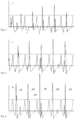
- FIG. 1 shows a hammer drill
- FIG. 2 shows acceleration signals at a low pressing force
- FIG. 3 shows acceleration signals at a medium pressing force
- FIG. 4 shows acceleration signals at a high pressing force
- FIG. 1 schematically shows a hammer drill 1 as an example of a portable hand-held power tool.
- the illustrative hammer drill 1 has a tool holder 2 , into which a tool 3 can be inserted and locked.
- the tool 3 is for example a drill bit, a chisel etc.
- the embodiment illustrated by way of example turns the tool holder 2 about a working axis 4 and at the same time exerts periodic impacts on the tool along the working axis 4 .
- the hand-held power tool 1 can have a mode selector switch 5 , which allows the user to selectively activate and deactivate the rotational movement and selectively activate and deactivate the percussive operation.
- the hand-held power tool 1 has a handle 6 .
- the user can hold and guide the hand-held power tool 1 during operation by way of the handle 6 .
- the operating button 7 is preferably attached to the handle 6 in such a way that the user can operate the operating button 7 using the hand holding the handle 6 .
- the handle 6 can be decoupled from a machine housing 8 by way of damping elements.
- the hand-held power tool 1 is switched on and off by the operating button 7 .
- the operating button 7 is arranged in the handle 6 . The user can actuate the operating button 7 preferably using the hand holding the handle 6 .
- the hand-held power tool 1 has a rotary drive 9 , which is coupled to the tool holder 2 .
- the rotary drive 9 can have a step-down gear mechanism 10 and a slip clutch 11 .
- An output shaft 12 of the rotary drive 9 is connected to the tool holder 2 .
- the rotary drive 9 is coupled to an electric motor 13 .
- the user can switch the electric motor 13 on and off by actuating the operating button 7 , wherein the operating button 7 accordingly controls a power supply to the electric motor 13 .
- a rotational speed of the electric motor 13 can be set by way of the operating button 7 .
- the hand-held power tool 1 has a pneumatic impact mechanism 14 .
- the pneumatic impact mechanism 14 has an exciter piston 15 and an impact piston 16 .
- the exciter piston 15 is permanently coupled to the electric motor 13 . Since the exciter piston 15 is permanently coupled to the electric motor 13 , the exciter piston 15 moves as soon as the electric motor 13 rotates, i.e. when the user actuates the operating button 7 .
- the ratio of the rotational speed of the electric motor 13 to the periodicity of the movement of the exciter piston 15 is predefined by the transmission components in the drive train between electric motor 13 and exciter piston 15 .
- transmission components are an eccentric wheel 17 and a connecting rod 18 , which convert the rotational movement of the electric motor 13 into a movement in translation on the working axis 4 .
- the exciter piston 15 and the impact piston 16 close off a pneumatic chamber 19 between one another.
- radial closure of the pneumatic chamber 19 is provided by a guide tube 20 , which at the same time guides the exciter piston 15 and the impact piston.
- the impact piston can be of hollow design and the exciter piston 15 is guided in the impact piston, or vice versa.
- the air enclosed in the pneumatic chamber 19 is compressed and decompressed by the exciter piston 15 .
- the changes in pressure couple the impact piston to the movement of the exciter piston 15 , and the pneumatic chamber 19 behaves in a similar manner to a spring, and is therefore also referred to as a pneumatic spring.
- the exciter piston 15 and the impact piston 16 can be configured as solid cylinders. In other embodiments, the exciter piston 15 can be configured in the form of a cup and the impact piston 16 is guided in the exciter piston 15 . Analogously, the exciter piston 15 can be guided in the impact piston 16 .
- the impact piston 16 can strike the tool 3 directly or strike the tool indirectly by way of an anvil 21 .
- the user exerts a force in the striking direction 22 on the handle 6 in order to press the tool 3 against the wall.
- the tool 3 is movable along the striking direction 22 in the tool holder 2 .
- the tool 3 is moved counter to the striking direction 22 in the tool holder 2 and in the process moves the anvil 21 until the latter comes to bear against a stop.
- This position of the anvil 21 is referred to as working position in the following text.
- the impact piston 16 strikes the anvil 21 in the working position thereof.
- the anvil 21 in the working position defines the running time and the running distance that the impact piston 16 covers between two strikes.
- the position in which the striker strikes the anvil 21 in the working position is referred to as striking point in the following text.
- the pressing force by the user has to be sufficient for the anvil 21 to return into the working position before each next strike. If the user does not exert any pressing force or exerts too little pressing force on the tool 3 , the anvil 21 is not pushed back into the working position after a strike. The anvil 21 is now located in an idle-strike position. In this case, the pneumatic impact mechanism 14 is deactivated automatically, in order to avoid damage to the hand-held power tool 1 and injuries to the user. The switch-off is effected by ventilation of the pneumatic chamber 19 . The impact piston 16 is no longer coupled to the exciter piston 15 , which continues to move, and comes to rest.
- Ventilation of the pneumatic chamber 19 can take place through ventilation openings in the guide tube 20 .
- the ventilation openings can be opened and closed for example by a path-controlled valve.
- a path-controlled valve is based on a lateral surface of the impact piston 16 , which, depending on its position, does or does not overlap the ventilation openings.
- the ventilation openings are closed when the impact piston 16 is ahead of the striking point in the striking direction.
- the pneumatic chamber 19 is active and the impact piston 16 is coupled to the exciter piston 15 . If the impact piston 16 goes beyond the striking point in the striking direction, the ventilation openings are open.
- the pneumatic chamber 19 is ventilated and thus deactivated.
- the air moved through the exciter piston 15 can flow in and out via the ventilation openings.
- the ventilation of the pneumatic chamber 19 can also take place other controlled valves.
- the ventilation can also take place indirectly or directly by way of the anvil 21 .
- the impact mechanism 14 is activated again when the user presses the tool 3 against the substrate.
- the ventilation openings 23 are closed and the impact piston 16 is coupled to the exciter piston 15 again.
- the impact mechanism 14 is deactivated again. The user has difficulty gaining control over the hand-held power tool 1 .
- the hand-held power tool 1 has a sensor system 24 for sensing the pressing force applied by the user.
- the sensor system 24 is based on an acceleration sensor 25 for sensing an acceleration of the machine housing 8 .
- the acceleration sensor 25 is arranged in the machine housing 8 . The arrangement is such that the acceleration sensor 25 can sense accelerations that arise in the impact mechanism 14 preferably in an undamped manner.
- the acceleration sensor 25 is arranged for example on the impact-mechanism housing 20 , for example the guide tube 20 or a component rigidly connected to the guide tube 20 .
- the impact-mechanism housing 20 undergoes acceleration depending on the movement of the impact piston 16 , anvil 21 and tool 3 , the type of tool 3 , the substrate to be worked on and on the behavior of the user, inter alia the pressing force exerted by the user.
- FIG. 2 , FIG. 3 , and FIG. 4 show the profile of the acceleration a as a function of time.
- an approximately periodic behavior of the acceleration is discernible.
- the amplitude varies from strike to strike, however. This is to be expected on account of the increasingly demolished substrate and the inhomogeneities thereof, and a slightly modified behavior of the user also makes a contribution.
- the brief and very high accelerations are able to be sensed only with a large tolerance; the accelerations are in the region of 10 times the acceleration due to gravity (dashed line). Therefore, the amplitude is not suitable for reliably determining the pressing force.
- the behavior of the acceleration at the time of rebound impact 26 of the anvil 21 proves to be a good indicator of the pressing force.
- the time and the duration until the rebound impact dissipates, i.e. the anvil 21 remains in its working position are dependent on the pressing force.
- the influence of the substrate and of the tool on the time and duration of the rebound impact indicates a different behavior than the influence thereof on the amplitude. This makes it possible to distinguish the different influences and to estimate the pressing force.
- Test series with the hand-held power tool 1 for different tools, different substrates and different pressing forces were carried out. From the specific acceleration curves for the hand-held power tool 1 and parameters are saved in parameterized form in a table.
- the table can be stored in a memory 27 in the sensor system 24 .
- the pressing force is can be determined on the basis of from the table and a currently recorded acceleration curve.
- the acceleration curve is parameterized. For the parameters obtained, the greatest correspondence in the table is determined and the associated pressing force is output.
- the sensor system 24 can also contain a sensor 28 for sensing a phase of the exciter piston 15 .
- the strictly periodic movement of the exciter piston 15 dominates the temporal sequence of the movement of the impact piston 16 and of the anvil 21 .
- the impact mechanism 14 has a compression phase 29 , when the exciter piston 15 and impact piston 16 , at their smallest distance from one another, compress the pneumatic chamber 19 .
- the impact piston 16 exerts the greatest reaction on the exciter piston 15 and thus the impact mechanism housing 20 at this time. Outside this compression phase, the impact piston 16 should, under optimal operating conditions, exert virtually no force on the impact mechanism housing 20 .
- the other peaks of the acceleration are caused substantially by the recoil of the anvil 21 or the impact of the impact piston 16 in damping elements.
- the evaluation of the acceleration a is based preferably on the peaks outside the compression phase.
- the peaks can be assigned to the different phases or the peaks outside the compression phase are selected for evaluating the pressing force.
- the knowledge of the current phase is important for precisely determining the time at which a peak, flank or other characteristics of the acceleration a arise(s).
- a zero point of the time can relate for example to a particular phase of the exciter piston 15 , for example the phase of the position, remote from the tool 3 , of the exciter piston 15 from the tool 3 .
- An evaluation unit 30 for determining the pressing force can contain a microprocessor or some other data processing device.
- the phase of the exciter piston 15 can take place by evaluation of the acceleration over time. However, several cycles and computing power are required for this.
- a sensor 28 can determine the phase of the exciter piston 15 .
- the sensor 28 can be integrated for example with the exciter piston 15 , with the transmission 10 or in the electric motor 13 .
- the sensor 28 is for example an angle sensor, an optical sensor, an electric sensor, etc.
- the motor controller or similar control unit 31 of the hand-held power tool 1 reduces the rotational speed of the electric motor 13 when the estimated pressing force is below a setpoint value.
- the rotational speed can be determined depending on the pressing force. For example, a table is saved in the motor controller 31 , which assigns a rotational speed to a pressing force. The assignment can also be saved in the sensor system 24 . A reduction in the rotational speed brings about a lower impact force of the impact mechanism 14 and can be kept in operation at a lower pressing force.
Landscapes
- Engineering & Computer Science (AREA)
- Mechanical Engineering (AREA)
- Percussive Tools And Related Accessories (AREA)
Applications Claiming Priority (4)
| Application Number | Priority Date | Filing Date | Title |
|---|---|---|---|
| EP19203810.7 | 2019-10-17 | ||
| EP19203810.7A EP3808506A1 (fr) | 2019-10-17 | 2019-10-17 | Machine-outil manuelle |
| EP19203810 | 2019-10-17 | ||
| PCT/EP2020/078041 WO2021073960A1 (fr) | 2019-10-17 | 2020-10-07 | Outil électrique portatif |
Publications (2)
| Publication Number | Publication Date |
|---|---|
| US20230021949A1 US20230021949A1 (en) | 2023-01-26 |
| US11904448B2 true US11904448B2 (en) | 2024-02-20 |
Family
ID=68281306
Family Applications (1)
| Application Number | Title | Priority Date | Filing Date |
|---|---|---|---|
| US17/760,675 Active US11904448B2 (en) | 2019-10-17 | 2020-10-07 | Hand-held power tool |
Country Status (3)
| Country | Link |
|---|---|
| US (1) | US11904448B2 (fr) |
| EP (2) | EP3808506A1 (fr) |
| WO (1) | WO2021073960A1 (fr) |
Citations (9)
| Publication number | Priority date | Publication date | Assignee | Title |
|---|---|---|---|---|
| EP1502710A2 (fr) | 2003-07-31 | 2005-02-02 | Makita Corporation | Outil électrique |
| US20100193205A1 (en) | 2009-01-30 | 2010-08-05 | Hilti Aktiengesellschaft | Control method and hand-held power tool |
| DE102009045758A1 (de) | 2009-10-16 | 2011-04-21 | Robert Bosch Gmbh | Handwerkzeug mit einer Werkstofferfassungsvorrichtung |
| DE202011110069U1 (de) | 2011-12-21 | 2013-02-08 | Robert Bosch Gmbh | Handwerkzeugmaschine |
| DE102012005803A1 (de) | 2012-03-21 | 2013-09-26 | Wacker Neuson Produktion GmbH & Co. KG | Bohr-und/oder Schlaghammer mit belastungsabhängiger Anpassung der Schlagzahl |
| US8955615B2 (en) * | 2009-01-30 | 2015-02-17 | Hilti Aktiengesellschaft | Pneumatic hammer mechanism |
| US20150101835A1 (en) | 2012-05-25 | 2015-04-16 | Robert Bosch Gmbh | Percussion Unit |
| US20150158170A1 (en) | 2012-05-25 | 2015-06-11 | Robert Bosch Gmbh | Hand-Held Power Tool |
| US10369686B2 (en) * | 2014-12-03 | 2019-08-06 | Hilti Aktiengesellschaft | Hand-held power tool and control method therefor |
-
2019
- 2019-10-17 EP EP19203810.7A patent/EP3808506A1/fr not_active Withdrawn
-
2020
- 2020-10-07 EP EP20781588.7A patent/EP4045231A1/fr active Pending
- 2020-10-07 WO PCT/EP2020/078041 patent/WO2021073960A1/fr unknown
- 2020-10-07 US US17/760,675 patent/US11904448B2/en active Active
Patent Citations (12)
| Publication number | Priority date | Publication date | Assignee | Title |
|---|---|---|---|---|
| EP1502710A2 (fr) | 2003-07-31 | 2005-02-02 | Makita Corporation | Outil électrique |
| US20050023017A1 (en) | 2003-07-31 | 2005-02-03 | Makita Corporation | Power tool |
| US7204322B2 (en) * | 2003-07-31 | 2007-04-17 | Makita Corporation | Power tool having pneumatic vibration dampening |
| US20100193205A1 (en) | 2009-01-30 | 2010-08-05 | Hilti Aktiengesellschaft | Control method and hand-held power tool |
| US8333251B2 (en) * | 2009-01-30 | 2012-12-18 | Hilti Aktiengesellschaft | Control method and hand-held power tool |
| US8955615B2 (en) * | 2009-01-30 | 2015-02-17 | Hilti Aktiengesellschaft | Pneumatic hammer mechanism |
| DE102009045758A1 (de) | 2009-10-16 | 2011-04-21 | Robert Bosch Gmbh | Handwerkzeug mit einer Werkstofferfassungsvorrichtung |
| DE202011110069U1 (de) | 2011-12-21 | 2013-02-08 | Robert Bosch Gmbh | Handwerkzeugmaschine |
| DE102012005803A1 (de) | 2012-03-21 | 2013-09-26 | Wacker Neuson Produktion GmbH & Co. KG | Bohr-und/oder Schlaghammer mit belastungsabhängiger Anpassung der Schlagzahl |
| US20150101835A1 (en) | 2012-05-25 | 2015-04-16 | Robert Bosch Gmbh | Percussion Unit |
| US20150158170A1 (en) | 2012-05-25 | 2015-06-11 | Robert Bosch Gmbh | Hand-Held Power Tool |
| US10369686B2 (en) * | 2014-12-03 | 2019-08-06 | Hilti Aktiengesellschaft | Hand-held power tool and control method therefor |
Non-Patent Citations (1)
| Title |
|---|
| International Searching Authority, International Search Report and Written Opinion in International Application No. PCT/EP2020/078041, dated Dec. 11, 2020. |
Also Published As
| Publication number | Publication date |
|---|---|
| WO2021073960A1 (fr) | 2021-04-22 |
| US20230021949A1 (en) | 2023-01-26 |
| EP3808506A1 (fr) | 2021-04-21 |
| EP4045231A1 (fr) | 2022-08-24 |
Similar Documents
| Publication | Publication Date | Title |
|---|---|---|
| US7320368B2 (en) | Power impact tool | |
| JP5412249B2 (ja) | 手持ち工具 | |
| CN101733735B (zh) | 手持式工具机装置 | |
| EP2944429A1 (fr) | Outil a impact | |
| WO2008149695A1 (fr) | Outil de percussion | |
| US20090195204A1 (en) | Power Tool Having Motor Speed Monitor | |
| EP2497607A1 (fr) | Outil motorisé | |
| US10821590B2 (en) | Striking hand-held machine tool | |
| EP2944428A1 (fr) | Outil d'impact | |
| US10414036B2 (en) | Control method for a hammer drill | |
| US20150202758A1 (en) | Percussion Unit | |
| US10052747B2 (en) | Hammer tool | |
| US20160271779A1 (en) | Handheld Machine Tool | |
| JP2008194817A (ja) | 空気圧式の打撃機構を備える手持工具装置 | |
| JP2007136662A (ja) | 手動式動力打ち込み機のための固定手段供給装置 | |
| KR102406100B1 (ko) | 충격식 휴대용 전동 공구를 위한 제어 방법 | |
| US20180361552A1 (en) | Striking hand-held tool | |
| US20110108301A1 (en) | Handheld power tool | |
| US11904448B2 (en) | Hand-held power tool | |
| US10675742B2 (en) | Striking hand-held machine tool | |
| US20170274517A1 (en) | Hand-held chiselling machine tool | |
| US11858102B2 (en) | Hand-held power tool | |
| CN112262020B (zh) | 手持式工具机 | |
| US11858104B2 (en) | Portable power tool | |
| US20100294525A1 (en) | Hand tool machine |
Legal Events
| Date | Code | Title | Description |
|---|---|---|---|
| FEPP | Fee payment procedure |
Free format text: ENTITY STATUS SET TO UNDISCOUNTED (ORIGINAL EVENT CODE: BIG.); ENTITY STATUS OF PATENT OWNER: LARGE ENTITY |
|
| AS | Assignment |
Owner name: HILTI AKTIENGESELLSCHAFT, LIECHTENSTEIN Free format text: ASSIGNMENT OF ASSIGNORS INTEREST;ASSIGNORS:BRALLA, DARIO;BINDER, ALBERT;CLAUSI, DONATO;AND OTHERS;SIGNING DATES FROM 20201116 TO 20201126;REEL/FRAME:059304/0740 |
|
| STPP | Information on status: patent application and granting procedure in general |
Free format text: DOCKETED NEW CASE - READY FOR EXAMINATION |
|
| STPP | Information on status: patent application and granting procedure in general |
Free format text: NON FINAL ACTION MAILED |
|
| STPP | Information on status: patent application and granting procedure in general |
Free format text: RESPONSE TO NON-FINAL OFFICE ACTION ENTERED AND FORWARDED TO EXAMINER |
|
| STPP | Information on status: patent application and granting procedure in general |
Free format text: FINAL REJECTION MAILED |
|
| STPP | Information on status: patent application and granting procedure in general |
Free format text: RESPONSE AFTER FINAL ACTION FORWARDED TO EXAMINER |
|
| STPP | Information on status: patent application and granting procedure in general |
Free format text: NOTICE OF ALLOWANCE MAILED -- APPLICATION RECEIVED IN OFFICE OF PUBLICATIONS |
|
| STPP | Information on status: patent application and granting procedure in general |
Free format text: PUBLICATIONS -- ISSUE FEE PAYMENT VERIFIED |
|
| STCF | Information on status: patent grant |
Free format text: PATENTED CASE |