US11889996B2 - Specimen collection container having a fluid separation chamber - Google Patents
Specimen collection container having a fluid separation chamber Download PDFInfo
- Publication number
- US11889996B2 US11889996B2 US15/884,906 US201815884906A US11889996B2 US 11889996 B2 US11889996 B2 US 11889996B2 US 201815884906 A US201815884906 A US 201815884906A US 11889996 B2 US11889996 B2 US 11889996B2
- Authority
- US
- United States
- Prior art keywords
- chamber
- fluid
- valve
- collection container
- closed position
- Prior art date
- Legal status (The legal status is an assumption and is not a legal conclusion. Google has not performed a legal analysis and makes no representation as to the accuracy of the status listed.)
- Active, expires
Links
- 239000012530 fluid Substances 0.000 title claims abstract description 134
- 238000000926 separation method Methods 0.000 title abstract description 5
- 230000007704 transition Effects 0.000 claims abstract description 14
- 238000002955 isolation Methods 0.000 claims abstract description 13
- 238000004891 communication Methods 0.000 claims abstract description 9
- 239000000463 material Substances 0.000 claims description 50
- 238000012360 testing method Methods 0.000 claims description 10
- 238000010521 absorption reaction Methods 0.000 claims description 5
- 210000002700 urine Anatomy 0.000 description 53
- 239000002250 absorbent Substances 0.000 description 50
- 230000002745 absorbent Effects 0.000 description 49
- 239000000843 powder Substances 0.000 description 13
- 241000894006 Bacteria Species 0.000 description 10
- 238000000034 method Methods 0.000 description 10
- 239000006096 absorbing agent Substances 0.000 description 8
- 230000008569 process Effects 0.000 description 6
- 238000011109 contamination Methods 0.000 description 5
- VYPSYNLAJGMNEJ-UHFFFAOYSA-N Silicium dioxide Chemical compound O=[Si]=O VYPSYNLAJGMNEJ-UHFFFAOYSA-N 0.000 description 4
- 230000002421 anti-septic effect Effects 0.000 description 4
- 150000001875 compounds Chemical class 0.000 description 4
- 239000007788 liquid Substances 0.000 description 4
- 229920001495 poly(sodium acrylate) polymer Polymers 0.000 description 4
- NNMHYFLPFNGQFZ-UHFFFAOYSA-M sodium polyacrylate Chemical compound [Na+].[O-]C(=O)C=C NNMHYFLPFNGQFZ-UHFFFAOYSA-M 0.000 description 4
- 239000005909 Kieselgur Substances 0.000 description 3
- 230000001580 bacterial effect Effects 0.000 description 3
- 239000000440 bentonite Substances 0.000 description 3
- 229910000278 bentonite Inorganic materials 0.000 description 3
- SVPXDRXYRYOSEX-UHFFFAOYSA-N bentoquatam Chemical compound O.O=[Si]=O.O=[Al]O[Al]=O SVPXDRXYRYOSEX-UHFFFAOYSA-N 0.000 description 3
- 239000011800 void material Substances 0.000 description 3
- 229920001661 Chitosan Polymers 0.000 description 2
- 229920002472 Starch Polymers 0.000 description 2
- 229920000615 alginic acid Polymers 0.000 description 2
- 235000010443 alginic acid Nutrition 0.000 description 2
- 229910052500 inorganic mineral Inorganic materials 0.000 description 2
- 239000011707 mineral Substances 0.000 description 2
- 238000012986 modification Methods 0.000 description 2
- 230000004048 modification Effects 0.000 description 2
- 239000008107 starch Substances 0.000 description 2
- 235000019698 starch Nutrition 0.000 description 2
- 239000010457 zeolite Substances 0.000 description 2
- 239000004793 Polystyrene Substances 0.000 description 1
- 230000009471 action Effects 0.000 description 1
- XAGFODPZIPBFFR-UHFFFAOYSA-N aluminium Chemical compound [Al] XAGFODPZIPBFFR-UHFFFAOYSA-N 0.000 description 1
- 229910052782 aluminium Inorganic materials 0.000 description 1
- 239000001913 cellulose Substances 0.000 description 1
- 229920002678 cellulose Polymers 0.000 description 1
- 239000004927 clay Substances 0.000 description 1
- 238000010276 construction Methods 0.000 description 1
- 239000000356 contaminant Substances 0.000 description 1
- 230000001419 dependent effect Effects 0.000 description 1
- 235000012489 doughnuts Nutrition 0.000 description 1
- 239000003814 drug Substances 0.000 description 1
- 229940079593 drug Drugs 0.000 description 1
- 238000000605 extraction Methods 0.000 description 1
- 239000000835 fiber Substances 0.000 description 1
- 238000007667 floating Methods 0.000 description 1
- 239000006260 foam Substances 0.000 description 1
- 239000011521 glass Substances 0.000 description 1
- 230000005484 gravity Effects 0.000 description 1
- 229920001903 high density polyethylene Polymers 0.000 description 1
- 239000004700 high-density polyethylene Substances 0.000 description 1
- 239000000123 paper Substances 0.000 description 1
- 239000002245 particle Substances 0.000 description 1
- -1 pelites Substances 0.000 description 1
- 229910052615 phyllosilicate Inorganic materials 0.000 description 1
- 229920000642 polymer Polymers 0.000 description 1
- 229920002223 polystyrene Polymers 0.000 description 1
- 238000013102 re-test Methods 0.000 description 1
- 229920006395 saturated elastomer Polymers 0.000 description 1
- 238000007789 sealing Methods 0.000 description 1
- 239000007787 solid Substances 0.000 description 1
- 238000012546 transfer Methods 0.000 description 1
- 208000019206 urinary tract infection Diseases 0.000 description 1
- 239000002699 waste material Substances 0.000 description 1
Images


Classifications
-
- A—HUMAN NECESSITIES
- A61—MEDICAL OR VETERINARY SCIENCE; HYGIENE
- A61B—DIAGNOSIS; SURGERY; IDENTIFICATION
- A61B10/00—Other methods or instruments for diagnosis, e.g. instruments for taking a cell sample, for biopsy, for vaccination diagnosis; Sex determination; Ovulation-period determination; Throat striking implements
- A61B10/0045—Devices for taking samples of body liquids
- A61B10/007—Devices for taking samples of body liquids for taking urine samples
-
- A—HUMAN NECESSITIES
- A61—MEDICAL OR VETERINARY SCIENCE; HYGIENE
- A61B—DIAGNOSIS; SURGERY; IDENTIFICATION
- A61B10/00—Other methods or instruments for diagnosis, e.g. instruments for taking a cell sample, for biopsy, for vaccination diagnosis; Sex determination; Ovulation-period determination; Throat striking implements
- A61B10/0096—Casings for storing test samples
Definitions
- the present invention is directed to a specimen collection container and, more particularly, a specimen collection container having two chambers separated by a valve for separating a patient's initially voided urine from the mid-stream portion of the urine sample.
- the sample When obtaining a urine sample for an ambulatory patient, it is generally preferable to collect the sample from the midstream portion of the urine stream. It is important to reject the “first-burst” urine from samples because the first volumes of voided urine carry a disproportionately higher level of bacteria. Bacteria is often picked up from external skin/tissue and also possibly from the urethral volume. The elevated bacteria level of the first stream or first-burst urine can lead to false-positive results for presence of bacteria, and could falsely suggest urinary tract infection, leading to unnecessary treatment or medication and inappropriate patient management. Since surface bacteria are always present, the chance for contamination of a urine sample is universal. As a result, urine samples are typically requested as “clean catch” or “mid-stream”.
- Such requests require the patient or a care provider to use antiseptic wipes to disinfect external tissue. Additionally, patients are instructed to allow the first urine to fall into the toilet before filling a sample collection cup. It is believed that the first-burst urine not only contains elevated bacteria from the tissue surface, but in fact “washes” the external surfaces, such that there is little or no errant surface bacteria captured in later midstream urine volumes.
- the state-of-the-art for midstream urine collection is essentially a manual process which relies entirely on the user or patient to perform the collection correctly.
- Typical instructions for midstream urine collection may require a user to void into the toilet, then stop urine flow, move the collection cup into position, void into the cup until it is full, stop the urine flow and move the filled cup away, and finish voiding into the toilet.
- a user will be instructed to clean the surrounding external tissue/skin with an antiseptic wipe before voiding. The process is messy, with a user's hands being near the urine stream and often exposing the user's skin to urine.
- Messiness and discomfort are not the only drawbacks from having a manual user-dependent process.
- patients need to be given adequate instructions placing an additional requirement and burden on both patient and caregiver.
- caregivers do not provide any instructions at all.
- patients may not understand or choose not to follow the instructions even when they are given, particularly if the patient is already nervous, scared, or agitated.
- there is significant anecdotal evidence of people not using the antiseptic wipes either because they burn or are uncomfortable or because patients mistake the antiseptic wipes for hand wipes to be used after providing the sample. Indeed, there is no way to know, short of actually watching the patient provide the urine sample, whether any of the instructions are actually followed.
- the frequency of bacterial contamination of urine samples ranges from 10-40%, depending on the nature of the tests and the institution where the studies are performed. Such statistics indicate that the problem is widespread and quite common. It likely contributes to significant waste, both in increased cost and time associated with handling poor samples or running tests that give ambiguous or potentially useless data. Retesting may be appropriate in some circumstances; however, especially in outpatient settings, the patient may not be available to provide a second sample. Consequently, a re-test is either never performed or simply never requested.
- the apparatus should be intuitive to use and should be designed to promote proper use and handling of the collected sample at all points before, during, and after voiding of urine. Further, the device should increase patient comfort and convenience by effectively selecting the midstream urine, so the user does not need to consciously force stop-then-start voiding. Not requiring the patient to start-stop-start voiding urine flow reduces the risk of natural physiologic contamination from stream interruption. Similarly, the device should require only minimal manipulation by a patient in order to collect the urine.
- the apparatus should eliminate the need for patients to be directly exposed to the urine stream.
- the device should include one or more access ports permitting direct flow of the collected sample from the container to a test tube.
- a specimen collection container having a fluid separation chamber for receiving a fluid stream and for separating an initial volume of the fluid stream from a midstream portion of the fluid stream.
- the specimen collection container further includes a port for accessing and removing the midstream portion of the fluid from the container and for transferring the midstream portion to a sample collection tube.
- a method for collecting a fluid sample using a specimen collection container having a fluid separation chamber is also disclosed.
- a specimen collection container includes a first chamber having an open top portion, a sidewall, and a bottom portion; a second chamber having a top, a closed bottom, and a sidewall; and a valve disposed between the first chamber and the second chamber.
- the valve is transitionable from an open position which permits fluid communication between the first chamber and the second chamber to a closed position which maintains fluid isolation between the first chamber and the second chamber.
- a predetermined volume of fluid, received in the first chamber may pass from the first chamber to the second chamber.
- the valve transitions from the open position to the closed position such that additional fluid received within the first chamber is maintained in the first chamber in fluid isolation from the predetermined volume of fluid contained in the second chamber.
- the valve of the specimen collection container includes a channel extending between the first chamber and the second chamber and an absorbent expandable material.
- the absorbent expandable material absorbs the predetermined volume of fluid and expands to engage with the channel thereby transitioning the valve to the closed position.
- the container further comprises a gasket such that expansion of the absorbent expandable material positions the gasket to transition the valve.
- the absorbent expandable material may be a sponge.
- the valve includes a channel, extending between the first chamber and the second chamber, and a buoyant float.
- the buoyant float engages the channel by a buoyancy force exerted on the float by the predetermined volume of fluid to transition the float from the open to the closed position.
- a portion of the buoyant float initially seals the channel. Fluid passing from the first chamber to the second chamber disengages the float from the channel placing the valve in the temporarily open position.
- the specimen collection container further includes a port for accessing and removing a fluid sample from the first chamber.
- the port may include a nozzle defining a channel between the first chamber and an exterior of the specimen collection container; and a septum covering the channel which transitions from a closed position to an open position to allow removal of the fluid sample therefrom.
- the port may be disposed within the sidewall of the first chamber.
- the port may also include a needle having an external tip, an internal tip adjacent the first chamber, and a needle cannula extending therebetween, wherein fluid access to the first container is established through the needle cannula.
- the external tip of the needle is recessed with respect to an external surface of the collection container for safe handling of the device.
- a specimen collection container includes an interior chamber having a bottom portion, a sidewall, and an open top; and an absorber disposed within the interior chamber which absorbs a predetermined volume of fluid. When a fluid stream enters the chamber through the open top, the absorber absorbs the predetermined volume. Additional fluid from the fluid stream is maintained in the internal chamber in fluid isolation from the fluid absorbed by the absorber.
- the absorber includes bentonite, diatomaceous earth, pelites, zeolites, chitosan, alginates, starch-based powders, and/or sodium polyacrylate.
- the absorber may include a powder.
- the absorber may include a pouch enclosing an absorbent material.
- the interior chamber includes a screen separating the interior chamber into a first chamber and a second chamber with the absorber maintained therein.
- the screen permits fluid to pass from the first chamber to the second chamber but prevents the absorber from passing from the second chamber to the first chamber.
- a specimen collection container includes a first chamber having an open top portion, a sidewall, and a bottom portion; a second chamber having a top, a closed bottom, and a sidewall; and a valve disposed between the first chamber and the second chamber.
- the valve is transitionable from a first closed position in which the first chamber and the second chamber are in fluid isolation, to an open position which permits fluid communication between the first chamber and the second chamber, to a second closed position in which fluid isolation between the first chamber and the second chamber is restored.
- the valve may include a spring action flapper valve.
- a fluid entering the first chamber transitions the valve from the first closed position to the open position and the presence of a predetermined volume of fluid within the second chamber transitions the valve from the open position to the second closed position.
- the valve includes a flapper valve transitionable from the first closed position to the open position when fluid contacts the surface of the flapper adjacent the first chamber. The valve is also subsequently transitionable from the open position to the second closed position when a predetermined volume of fluid received within the second chamber contacts the surface of the flapper adjacent the second chamber.
- FIG. 1 A is a cross-sectional front view of a specimen collection container with a valve in the open position in accordance with an embodiment of the present invention.
- FIG. 1 B is a cross-sectional front view of the container of FIG. 1 A with the valve in the closed position in accordance with an embodiment of the present invention.
- FIG. 2 A is a cross-sectional front view of a specimen collection container with a valve in the open position in accordance with an embodiment of the present invention.
- FIG. 2 B is a cross-sectional front view of the container of FIG. 2 A with the valve in the closed position in accordance with an embodiment of the present invention.
- FIG. 3 A is a cross-sectional front view of a specimen collection container with a valve in the open position in accordance with an embodiment of the present invention.
- FIG. 3 B is a cross-sectional front view of the container of FIG. 3 A with the valve in the closed position in accordance with an embodiment of the present invention.
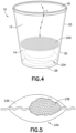
- FIG. 4 is a perspective view of a specimen collection container having an absorbent pouch in accordance with an embodiment of the present invention.
- FIG. 5 is a perspective view of the absorbent pouch of FIG. 4 , in accordance with an embodiment of the present invention, with a partial cut-away portion to reveal the interior of the pouch.
- FIG. 6 is a perspective view of a specimen collection container having an absorbent material in accordance with an embodiment of the present invention.
- FIG. 7 is a cross-sectional front view of a specimen collection container, having an outflow port, in accordance with an embodiment of the present invention.
- FIG. 8 is a cross-sectional front view of a specimen collection container, in accordance with an embodiment of the present invention, having a sharps-free elastomeric port.
- FIG. 9 is a cross-sectional front view of the specimen collection container of FIG. 8 engaged with a sample collection tube for removing a sample from the container, in accordance with an embodiment of the present invention.
- FIG. 10 is a cross-sectional front view of a sample collection tube, in accordance with an embodiment of the present invention.
- FIG. 11 A is a top view of an absorbent material for use in a specimen collection container, in accordance with an embodiment of the present invention.
- FIG. 11 B is a top view of an absorbent material for use in a specimen collection container, in accordance with an embodiment of the present invention.
- FIG. 11 C is a top view of an absorbent material for use in a specimen collection container, in accordance with an embodiment of the present invention.
- FIG. 11 D is a top view of an absorbent material for use in a specimen collection container, in accordance with an embodiment of the present invention.
- FIG. 11 E is a perspective view of an absorbent material for use in a specimen collection container, in accordance with an embodiment of the present invention.
- a specimen collection container 10 includes a first chamber 12 in fluid communication with a second chamber 14 through a valve 16 .
- the specimen collection container 10 is adapted to receive and separate a fluid stream into an initial or void volume and a midstream or sample volume.
- the midstream or sample volume can be removed from the specimen collection container 10 for biological testing.
- the container 10 is formed from any relatively inert medical grade polymer such as high density polyethylene or polystyrene.
- the container 10 may be formed from glass, paper or cellulose-based products.
- the specimen collection container 10 includes a first chamber 12 having an open top portion 18 , a sidewall 20 , and a closed bottom portion 22 .
- the sidewall 20 may be sloped toward the bottom portion 22 of the first chamber 12 giving the first chamber 12 a funnel shape such that the diameter A of the open top portion 18 is larger than the diameter B of the closed bottom portion 22 . In this configuration, fluid introduced to the funnel shaped chamber more easily slides downward towards the bottom of the container.
- the first chamber 12 may include a fluid volume indicator 44 to show the amount of fluid contained therein.
- the first chamber 12 may be covered by a removable lid 24 which can be placed over the open top 18 of the first chamber 12 after the fluid sample is introduced to the chamber 12 .
- the lid 24 prevents the fluid sample from leaking from the container 10 and prevents the sample from being contaminated.
- the first chamber 12 is in fluid communication with the second chamber 14 .
- the second chamber 14 includes a closed top 26 , sidewall 20 , and closed bottom 28 .
- the second chamber 14 is positioned below the first chamber 12 such that the bottom portion 22 of the first chamber 12 also forms the closed top 26 of the second chamber 14 .
- the second chamber 14 has a volume of about 12 mL to 15 mL which may be smaller than the volume of the first chamber 12 .
- valve 16 Fluid communication between the first chamber 12 and the second chamber 14 is established through the valve 16 .
- the valve 16 transitions from a first position in which fluid communication between the first chamber 12 and second chamber 14 is established to a second position in which the first chamber 12 and the second chamber 14 are held in fluid isolation.
- valve 16 includes a channel 32 that connects the first chamber 12 with the second chamber 14 .
- the channel 32 is blocked to prevent fluid in the first chamber 12 from flowing to the second chamber 14 .
- the valve 16 prevents fluid contained in the second chamber 14 from passing back to the first chamber 12 .
- fluid follows fluid flow path L 2 . In the open position, fluid flow L 1 is permitted between the first chamber 12 and the second chamber 14 through the channel 32 .
- the valve 16 includes an expandable absorbent material 34 , such as a compressed sponge, contained within the second chamber 14 .
- the absorbent material 34 may be glued to the closed bottom 28 of the second chamber 14 .
- the absorbent material 34 has a diameter of 1.7 inches and an expanded height of about 5 ⁇ 8 inch. In comparison, the height of the second chamber 14 is about 1 ⁇ 2 inch. Consequently, when expanded, the absorbent material 34 takes up an entire volume of the second chamber 14 . When wetted, the absorbent material 34 expands upward toward the closed top 26 to engage the channel 32 .
- the absorbent material 34 may be formed in any configuration which allows for rapid fluid absorption and expansion in size.
- Some configurations increase the absorption rate by increasing the surface area of the absorbent material 34 .
- possible shapes of the absorbent material 34 include, but are not limited to, a cylinder, a cylindrical shaped object with perforated holes, a cylindrical shape with wedges removed, a donut shape, and a plurality of separate thinner cylinders.
- the second chamber 14 includes a ribbed base 36 .
- the absorbent material 34 is placed on the ribbed base 36 or similar support structure.
- the support structure elevates the absorbent material 34 permitting fluid to collect in the space 38 beneath the absorbent material 34 and allowing the fluid to be absorbed by a bottom surface of the absorbent material 34 . Exposing an additional surface of the absorbent material 34 to fluid increases the absorption rate.
- the valve 16 further includes a gasket 40 for creating a water-tight seal in the channel 32 , as shown in FIGS. 1 A- 1 B .
- the gasket 40 is attached to a top portion of the absorbent material 34 .
- the gasket 40 can be, for example, a polymeric foam disk. It is noted that the gasket 40 effectively blocks a portion of the absorbent material 34 from absorbing liquid. Accordingly, it is important that other surfaces of the absorbent material 34 are accessible to fluid flow L 1 so that the absorbent material 34 expands as quickly as possible.
- the gasket 40 engages the channel 32 , thereby sealing the channel 32 and, effectively, transitioning the valve 16 to the closed position.
- the first chamber 12 and the second chamber 14 are in fluid isolation from one another. Accordingly, any additional fluid that enters the first chamber 12 through the open top 18 is maintained in the first chamber 12 .
- This fluid maintained in the first chamber 12 is the midstream urine sample.
- the valve 16 consists of a buoyant float 142 which is forced in an upward direction toward the channel 32 as the fluid level of the second chamber 14 rises.
- the buoyant float 142 includes gasket 40 for forming a seal between the float 142 and channel 32 .
- the valve 16 is a “flapper valve”.
- a portion 144 of the float 142 is attached to the closed top 26 of the second chamber 14 forming a hinge 146 .
- the hinge 146 is a living hinge.
- the flapper valve includes a mechanical spring. The float 142 is held in close proximity to the channel 32 such that, initially, the float 142 covers the channel 32 . Force exerted on the float 142 from fluid flow L 1 entering the first chamber 12 pushes the float 142 away from the channel 32 allowing fluid to pass directly through the channel 32 from the first chamber 12 to the second chamber 14 .
- the range of movement for the float 142 is reduced, until, ultimately, the float 142 is held in place against the top 26 of the second chamber 14 and the channel 32 . Once the float 142 is in place against the channel 32 , fluid flow L 2 from the first chamber 12 to the second chamber 14 is blocked. Therefore, additional fluid introduced to the first chamber 12 is collected and maintained in the first chamber 12 .
- the fluid collected within the first chamber 12 is the midstream portion of the urine stream.
- the valve 16 of the specimen collection container 10 may also include both a float 142 and expandable absorbent material 34 .
- the absorbent material 34 increases in size eventually contacting the float 142 of the flapper valve 16 and forcing the float 142 toward the channel 32 to form a seal.
- the absorbent material 34 maintains the float 142 in the closed position, thereby ensuring that the first chamber 12 and the second chamber 14 remain in fluid isolation even when the specimen container is jostled or moved.
- an absorbent pouch 234 is included within the sample collection container 10 .
- the pouch 234 may be a non-woven filter paper bag 236 enclosing a micro-absorbent powder 238 . Fluid enters the container according to fluid flow L.
- the pouch 234 absorbs a first predetermined volume of the fluid.
- the absorbed portion corresponds with the initial burst or voided urine which is held in isolation in the second chamber in the embodiments of the invention described above.
- any additional fluid introduced to the container 10 is maintained in the container 10 in liquid form.
- the container 10 includes a screen 240 separating the first chamber 12 from the second chamber 14 .
- the screen 240 effectively holds the pouch 234 within the second chamber 14 and prevents the pouch from floating toward the top of the container as the fluid level increases.
- the screen 240 could be formed from a wire mesh or from a disk having a plurality of perforated holes.
- the first chamber 12 and the second chamber 14 are separated by a piece of filter paper 340 .
- the second chamber 14 contains an absorbent powder 334 .
- the absorbent powder 334 may be a mineral based compound or a synthetic compound. Examples of mineral based absorbent compounds include bentonite and diatomaceous earth. Bentonite is an absorbent aluminum phyllosilicate formed from impure clay. Diatomaceous earth is a compound composed of absorbent silica particles. Other natural absorbent materials include: pelites, zeolites, and chitosan.
- Organic absorbent powders are commercially available from a number of sources including: Sigma-Aldrich, LLC, MedTrade Products Ltd., and Haliburton. Absorbent alginates or starch based powders can also be used within the scope of the invention. Most synthetic absorbent powders are formed from sodium polyacrylate. One commercially available sodium polyacrylate powder is “Insta-Snow” produced by Steve Spangler, Inc. of Englewood, Colo.
- the absorbent powder When wetted, the absorbent powder forms a solid structure which will not pass through the filter paper 340 , thereby separating the first chamber 12 from the second chamber 14 .
- the powder 334 holds a predetermined initial volume of fluid. Once the powder 334 is saturated, any additional fluid introduced to the container 10 is maintained in the container 10 in liquid form. As with previous embodiments described above, the unabsorbed liquid portion constitutes the midstream urine sample.
- fiber papers are known in the art which are impregnated with sodium polyacrylate particles. Absorbent paper of this type is made by Safetec of America, Inc. located in Buffalo, N.Y. One or more pieces of the absorbent paper are placed in the second chamber 14 of the container 10 . The absorbent paper is used to absorb a first-burst of fluid in much the same way as the absorbent powder.
- the invention further includes an outflow port 50 for removing the sample (e.g., the midstream urine) from the sample container 10 .
- the outflow port 50 comprises a needle 52 having a needle cannula 59 for accessing the sample contained in the first chamber 12 .
- the needle 52 may be located in a cut-away portion 56 of the sidewall 20 or lid 24 such that a proximal end 83 of the needle 52 is recessed from the surfaces of the container 10 .
- the needle 52 is in contact with an access tube 58 that extends into the first chamber 12 of the container 10 . Fluid passes through access tube 58 before entering the needle cannula 54 for removal from the container 10 .
- a user places a sample collection tube 510 (e.g., a test tube) over the needle 52 .
- the tube 510 includes an open end 512 covered by a stopper 514 having a pierceable septum 516 .
- the needle 52 pierces the septum 516 accessing an interior portion 518 of the tube 510 and creating a fluid connection between the first chamber 12 and the tube 510 through the needle cannula 54 .
- the sample collection tube 510 may be evacuated such that upon engagement with the container 10 , fluid is drawn from the container interior into the sample collection tube 510 by vacuum draw.
- the entire container assembly may be inverted allowing fluid (e.g., the midstream urine sample) to flow from the collection container 10 to the specimen collection tube 510 .
- a sharps free port 70 extends from either the sidewall 20 or lid 24 of the first chamber 12 .
- the sharps free port 70 includes a nozzle 72 extending from the container 10 or lid 24 .
- a channel 74 is defined through the nozzle 72 allowing access to the first chamber 12 .
- An elastomeric seal 76 covers the channel 74 preventing fluid from leaking from the port 70 until a user is prepared to collect the fluid in a specimen collection tube 410 , as shown in FIG. 9 .
- the specimen collection tube 410 has an open top 412 covered by a stopper or flip-cap closure 414 .
- the flip-cap closure 414 includes an access tube 418 .
- the access tube 418 fits within the channel 74 of the nozzle 72 and pushes the elastomeric seal 76 out of the way to establish a fluid connection between the first chamber 12 and the sample collection tube 410 .
- the container 10 is inverted allowing the fluid sample to flow, along flow path L 3 , from the first chamber 12 to the collection tube 410 by gravity.
- the flip-cap closure 414 may further include a vent 420 allowing air displaced by the fluid sample to escape from the enclosed tube 410 .
- the presently claimed sample collection container 10 is used to collect a sample of midstream urine for testing.
- a patient directs a urine stream to the container 10 through the open top 18 of the first chamber 12 .
- the urine stream flows down the sidewall 20 toward the channel 32 and valve 16 .
- the first chamber 12 is funnel shaped having a sloped sidewall 20 .
- the sloped sidewall 20 allows fluid to more easily flow downward toward the bottom 22 of the first chamber 12 .
- the funnel shaped first chamber 12 also ensures that all of the first-burst or first urine stream will pass through the first chamber 12 and enter the second chamber 14 . For containers having straight sides and right angled corners, a portion of the first-burst may pool in the first chamber 12 , potentially contaminating the fluid sample.
- the fluid stream passes through the channel 32 and valve 16 and collects in the second chamber 14 .
- the valve 16 transitions from an open to a closed position.
- the pre-determined volume for the second chamber 14 may be between about 12 mL and 15 mL.
- the valve 16 should not transition to the closed position until the pre-determined volume of fluid passes to the second chamber 14 . If the valve 16 closes too soon, a portion of the initial burst of urine will be trapped in the first chamber 12 contaminating the midstream urine sample. If the valve 16 closes too slowly, some of the first-burst urine, which initially passed to the second chamber 14 , will flow back to the first chamber 12 contaminating the urine sample contained in the first chamber 12 .
- the specimen collection container 10 is removed from the urine stream. Alternatively, the patient may consciously stop urine flow to prevent overflowing the container 10 .
- the container 10 may include a fluid level indicator line 44 to inform the patient when the necessary amount of fluid has been collected.
- the lid 24 is then placed over the open top 18 of the first chamber 12 to prevent fluid from leaking from the container 10 or from being contaminated.
- the midstream urine sample is then removed from the first chamber 12 through the outflow port 50 or from the sharps free port 70 using any of the extraction procedures described above.
Abstract
Description
Claims (20)
Priority Applications (1)
| Application Number | Priority Date | Filing Date | Title |
|---|---|---|---|
| US15/884,906 US11889996B2 (en) | 2013-01-29 | 2018-01-31 | Specimen collection container having a fluid separation chamber |
Applications Claiming Priority (2)
| Application Number | Priority Date | Filing Date | Title |
|---|---|---|---|
| US13/752,590 US9913627B2 (en) | 2013-01-29 | 2013-01-29 | Specimen collection container having a fluid separation chamber |
| US15/884,906 US11889996B2 (en) | 2013-01-29 | 2018-01-31 | Specimen collection container having a fluid separation chamber |
Related Parent Applications (1)
| Application Number | Title | Priority Date | Filing Date |
|---|---|---|---|
| US13/752,590 Continuation US9913627B2 (en) | 2013-01-29 | 2013-01-29 | Specimen collection container having a fluid separation chamber |
Publications (2)
| Publication Number | Publication Date |
|---|---|
| US20180168557A1 US20180168557A1 (en) | 2018-06-21 |
| US11889996B2 true US11889996B2 (en) | 2024-02-06 |
Family
ID=47684056
Family Applications (3)
| Application Number | Title | Priority Date | Filing Date |
|---|---|---|---|
| US13/752,590 Active 2034-06-26 US9913627B2 (en) | 2013-01-29 | 2013-01-29 | Specimen collection container having a fluid separation chamber |
| US15/884,948 Active 2034-04-23 US11246572B2 (en) | 2013-01-29 | 2018-01-31 | Specimen collection container having a fluid separation chamber |
| US15/884,906 Active 2034-06-10 US11889996B2 (en) | 2013-01-29 | 2018-01-31 | Specimen collection container having a fluid separation chamber |
Family Applications Before (2)
| Application Number | Title | Priority Date | Filing Date |
|---|---|---|---|
| US13/752,590 Active 2034-06-26 US9913627B2 (en) | 2013-01-29 | 2013-01-29 | Specimen collection container having a fluid separation chamber |
| US15/884,948 Active 2034-04-23 US11246572B2 (en) | 2013-01-29 | 2018-01-31 | Specimen collection container having a fluid separation chamber |
Country Status (10)
| Country | Link |
|---|---|
| US (3) | US9913627B2 (en) |
| EP (2) | EP3574843A3 (en) |
| JP (1) | JP6169728B2 (en) |
| CN (2) | CN108652677B (en) |
| AU (1) | AU2013377104B2 (en) |
| BR (1) | BR112015018173B1 (en) |
| CA (3) | CA3024248C (en) |
| ES (1) | ES2740475T3 (en) |
| MX (1) | MX370078B (en) |
| WO (1) | WO2014120133A1 (en) |
Families Citing this family (33)
| Publication number | Priority date | Publication date | Assignee | Title |
|---|---|---|---|---|
| US10479536B2 (en) * | 2012-09-17 | 2019-11-19 | Portland Outdoors, Llc | System, methods and apparatus for urine collection and storage |
| USD740408S1 (en) * | 2013-07-26 | 2015-10-06 | Sekisui Medical Co., Ltd. | Collection tool |
| USD741993S1 (en) * | 2013-07-26 | 2015-10-27 | Sekisui Medical Co., Ltd. | Container for diluting samples with collection tool |
| USD739006S1 (en) * | 2013-07-26 | 2015-09-15 | Sekisui Medical Co., Ltd. | Sample dilution container |
| US11457899B2 (en) | 2014-09-30 | 2022-10-04 | Exosome Diagnostics, Inc. | Apparatuses, methods, and systems for sample collection and dispersion |
| CN107206381A (en) * | 2015-02-20 | 2017-09-26 | 文塔纳医疗系统公司 | Component for storing and transporting the tissue samples of immersion in a fluid |
| WO2016203467A1 (en) * | 2015-06-15 | 2016-12-22 | Tah Peekaboo Medical Ltd. | Device, system and method for urine collection |
| WO2017078493A1 (en) * | 2015-11-06 | 2017-05-11 | 가톨릭대학교 산학협력단 | Improved urine test container for urine separation and infection control |
| KR101732843B1 (en) * | 2015-11-06 | 2017-05-24 | 가톨릭대학교 산학협력단 | Advanced Urine container for separating a urine sample and infection management |
| CN108700564B (en) * | 2015-11-09 | 2021-09-24 | 诺凡麦制药有限公司 | Body fluid collection and diagnostic device |
| US11648179B2 (en) | 2016-05-16 | 2023-05-16 | Haemonetics Corporation | Sealer-less plasma bottle and top for same |
| EP3461259B1 (en) | 2016-05-16 | 2021-01-06 | Haemonetics Corporation | Sealer-less plasma bottle and top for same |
| CN106018000A (en) * | 2016-07-06 | 2016-10-12 | 江苏科华医疗器械科技有限公司 | Quantitative urine receiving urine cup with cup saucer |
| CN106017999A (en) * | 2016-07-06 | 2016-10-12 | 江苏科华医疗器械科技有限公司 | Urine cup allowing midstream urine convenient to collect |
| WO2018051256A2 (en) * | 2016-09-14 | 2018-03-22 | Curas Ltd. | A method and a receptacle bag for emptying a urinary bag |
| US10995867B2 (en) * | 2018-01-16 | 2021-05-04 | Tesla, Inc. | Automatic reset flood valve |
| CN108469360B (en) * | 2018-03-30 | 2020-12-22 | 江苏科华医疗器械科技有限公司 | Urine sample cup guide movable urine sampler |
| CN108814652B (en) * | 2018-03-30 | 2021-01-22 | 江苏科华医疗器械科技有限公司 | Elastomer stable transition type urine sampler |
| FR3086836B1 (en) * | 2018-10-03 | 2022-02-11 | Novandsat | ANIMAL URINE COLLECTION DEVICE |
| CN109350128B (en) * | 2018-10-18 | 2021-08-27 | 鹤壁市人民医院 | Urine sample collector |
| CN109692019B (en) * | 2018-12-20 | 2021-04-23 | 河南科技大学第一附属医院 | Rotation type urine examination sampling device |
| CN109646057B (en) * | 2019-02-17 | 2021-08-03 | 商丘市第一人民医院 | Male urine sampler and using and mounting method thereof |
| CN109612779B (en) * | 2019-02-28 | 2021-03-12 | 栾东存 | Boiler water quality sampling detection device |
| GB2583749A (en) * | 2019-05-08 | 2020-11-11 | Enterobiotix Ltd | A collection container |
| US11751855B2 (en) * | 2019-06-19 | 2023-09-12 | Varda Margalit Aberbach | Collecting urine samples and data thereof |
| WO2021142510A1 (en) * | 2020-01-15 | 2021-07-22 | C Lau Pty Ltd | Improved continence pad |
| CN111297545B (en) * | 2020-03-19 | 2022-05-24 | 川北医学院附属医院 | Disposable baby girl connects urine ware |
| CN111568475B (en) * | 2020-05-21 | 2023-06-02 | 王金燕 | Body fluid collecting and preserving device for clinical medicine inspection body fluid assay |
| IT202100002909A1 (en) * | 2021-02-10 | 2022-08-10 | Bios Health Diagnostics S R L | CONTAINER LID EQUIPPED WITH CLOSABLE THROUGH OPENING |
| IT202100004709A1 (en) * | 2021-03-01 | 2022-09-01 | Nico Innovagroupo S R L | SAFETY SYSTEM FOR URINE COLLECTION CONTAINER FOR SUBSEQUENT LABORATORY TESTS AND RELATED METHOD OF USE |
| WO2022251089A1 (en) * | 2021-05-24 | 2022-12-01 | Twenty Twenty Therapeutics Llc | Combined biological sampling and injection assemblies and associated devices, systems, and methods |
| CN114753459B (en) * | 2022-04-20 | 2023-10-31 | 扬州大学 | Closestool with disease detection function |
| GB2621386A (en) * | 2022-08-11 | 2024-02-14 | Owen Mumford Ltd | Apparatus for facilitating forestream collection of urine |
Citations (29)
| Publication number | Priority date | Publication date | Assignee | Title |
|---|---|---|---|---|
| US3928875A (en) | 1973-02-20 | 1975-12-30 | Sture Ivan Persson | Throw-away receptacle for collection of urine of those confined to bed |
| US4106497A (en) | 1977-02-04 | 1978-08-15 | Becton, Dickinson And Company | Multiple sample needle assembly with indicator means |
| US4494581A (en) | 1983-02-18 | 1985-01-22 | Whitman Medical Corporation | Isolation of forestream and midstream portions of collected urine samples |
| US4769215A (en) | 1987-03-24 | 1988-09-06 | Franklin Diagnostics, Inc. | Integrity preserving and determining urine sample collection apparatus |
| US4873193A (en) * | 1987-08-26 | 1989-10-10 | Forensic Applications Corporation | Method and apparatus for the collection and preservation of fluid biological evidence |
| US5374250A (en) | 1993-11-01 | 1994-12-20 | Dixon; Richard E. | Safety syringe |
| US5380289A (en) | 1993-01-19 | 1995-01-10 | The Board Of Regents Of The University Of Oklahoma | Fluid collection device |
| US5431548A (en) | 1993-07-12 | 1995-07-11 | Koble, Jr.; Robert L. | Single suction inlet evaporative cooler pump apparatus |
| US5895704A (en) * | 1995-11-27 | 1999-04-20 | Boeringer Mannheim Gmbh | Article for collecting and transporting a sample to be analyzed |
| US20020072702A1 (en) | 2000-11-13 | 2002-06-13 | Quay Steven C. | Devices and methods for obtaining mammary fluid samples for evaluating breast diseases, including cancer |
| US20030022392A1 (en) | 2001-07-25 | 2003-01-30 | Hudak Robert Thomas | Specimen collection container |
| JP2003139780A (en) | 2001-08-17 | 2003-05-14 | Becton Dickinson & Co | Liquid specimen collecting system |
| WO2004026166A2 (en) | 2002-09-18 | 2004-04-01 | Arcus Medical, Llc | Collection bag adapted for use in an incontinence management system |
| WO2005003725A2 (en) | 2003-06-28 | 2005-01-13 | Yong Peter A K | Dual-chamber liquid receiving and containing device |
| US20050131361A1 (en) | 2002-09-18 | 2005-06-16 | Mark Miskie | Receptacle for a male incontinence device |
| US6939312B2 (en) | 2000-03-27 | 2005-09-06 | Lifescan, Inc. | Method and device for sampling and analyzing interstitial fluid and whole blood samples |
| US7077833B2 (en) | 2003-10-07 | 2006-07-18 | Uro Concepts Inc. | Convenient urology undergarment pant system for urine collection |
| CN1845700A (en) | 2003-06-28 | 2006-10-11 | 彼得·A·K·勇 | Dual-chamber liquid receiving and containing device |
| US20070270708A1 (en) | 1999-12-28 | 2007-11-22 | David Hung | Devices, methods and systems for collecting material from a breast duct |
| US20090281485A1 (en) | 2006-11-06 | 2009-11-12 | Aadvark Medical, Llc | Irrigation and aspiration devices and methods |
| US7674434B2 (en) | 2006-11-27 | 2010-03-09 | Cytyc Corporation | Vials and apparatus for obtaining an aliquot of a sample |
| US20100137743A1 (en) | 2005-07-05 | 2010-06-03 | C. R. Bard, Inc. | Multi-functional and modular urine collection system |
| CN201535723U (en) | 2009-05-07 | 2010-07-28 | 阿尔法科技公司 | Novel test sample collecting, accumulating and dripping multifunctional device |
| US20110204084A1 (en) * | 1998-11-16 | 2011-08-25 | Aronowitz Jack L | Sample Collection System and Method for Use Thereof |
| US20110224610A1 (en) | 2010-03-15 | 2011-09-15 | Becton, Dickinson And Company | Medical Device Including an Air Evacuation System |
| JP2011182907A (en) | 2010-03-08 | 2011-09-22 | Livedo Corporation | Absorptive article |
| JP2012509489A (en) | 2008-11-18 | 2012-04-19 | ナイト サイエンティフィック リミテッド | First urine collector |
| US20120193376A1 (en) | 2011-02-01 | 2012-08-02 | Sakura Finetek U.S.A., Inc. | Fluid dispensing system |
| JP5664639B2 (en) | 2012-12-13 | 2015-02-04 | 株式会社三洋物産 | Electromagnet for solenoid, solenoid and gaming machine using the solenoid |
Family Cites Families (18)
| Publication number | Priority date | Publication date | Assignee | Title |
|---|---|---|---|---|
| EP0001339A1 (en) * | 1977-09-14 | 1979-04-04 | Medeci Developments Limited | Urine collection device |
| US4300404A (en) | 1977-12-01 | 1981-11-17 | Becton, Dickinson And Company | Liquid specimen container |
| US5042502A (en) * | 1989-09-18 | 1991-08-27 | La Mina Ltd. | Urine testing module with cytology cup |
| CN2137944Y (en) * | 1992-10-17 | 1993-07-14 | 董维树 | Closed urine collector with visible monitor for urination |
| CN2366110Y (en) * | 1999-01-20 | 2000-03-01 | 东营市人民医院 | Controlable urine bag |
| EP1707164B1 (en) * | 2000-03-30 | 2009-11-18 | Orde Levinson | Urine funnelling trumpet |
| JP3667203B2 (en) * | 2000-07-19 | 2005-07-06 | 住友ベークライト株式会社 | Urine weighing bag |
| US6537262B2 (en) * | 2001-06-13 | 2003-03-25 | Garey Thompson | Female urine collector |
| EP1421906B1 (en) * | 2002-11-20 | 2006-01-11 | Sarstedt AG & Co. | Urine collecting container |
| US7409953B2 (en) * | 2003-12-16 | 2008-08-12 | Kimberly-Clark Worldwide, Inc. | Surgical drape having an expandable member |
| CN2908779Y (en) * | 2006-02-07 | 2007-06-06 | 俞洪燕 | Gas-liquid multiphase flow separation rectifier |
| GB2435226A (en) * | 2006-02-07 | 2007-08-22 | Safety Kleen Europ Ltd | Separation apparatus and method |
| US7578308B2 (en) * | 2006-10-26 | 2009-08-25 | Delaware Capital Formation, Inc. | Emergency shutoff valve for use in a fuel dispensing system |
| JP5256295B2 (en) * | 2007-10-23 | 2013-08-07 | ベクトン・ディキンソン・アンド・カンパニー | Fluid transfer tissue container for molecular and tissue diagnostics |
| TWI373617B (en) * | 2009-03-03 | 2012-10-01 | Univ Nat Taiwan | Compact disk based system for separating immunomagnetic bead labeled particulates and method thereof |
| CA2785991C (en) * | 2009-12-30 | 2017-12-05 | Baxter International Inc. | Device and method for automatically opening and closing a material container during a lyophilization process |
| US8556784B2 (en) * | 2010-10-22 | 2013-10-15 | Barry Leibowitz | Step slide |
| US9227778B2 (en) * | 2012-12-11 | 2016-01-05 | Victor M. Aviles | Beverage cartridge |
-
2013
- 2013-01-29 US US13/752,590 patent/US9913627B2/en active Active
- 2013-01-30 EP EP19175850.7A patent/EP3574843A3/en active Pending
- 2013-01-30 CA CA3024248A patent/CA3024248C/en active Active
- 2013-01-30 CN CN201810201615.9A patent/CN108652677B/en active Active
- 2013-01-30 CN CN201380071677.8A patent/CN104955402B/en active Active
- 2013-01-30 AU AU2013377104A patent/AU2013377104B2/en active Active
- 2013-01-30 EP EP13703694.3A patent/EP2950719B1/en active Active
- 2013-01-30 CA CA3172804A patent/CA3172804A1/en active Pending
- 2013-01-30 JP JP2015555971A patent/JP6169728B2/en active Active
- 2013-01-30 ES ES13703694T patent/ES2740475T3/en active Active
- 2013-01-30 BR BR112015018173-2A patent/BR112015018173B1/en active IP Right Grant
- 2013-01-30 MX MX2015009285A patent/MX370078B/en active IP Right Grant
- 2013-01-30 CA CA2898731A patent/CA2898731C/en active Active
- 2013-01-30 WO PCT/US2013/023707 patent/WO2014120133A1/en active Application Filing
-
2018
- 2018-01-31 US US15/884,948 patent/US11246572B2/en active Active
- 2018-01-31 US US15/884,906 patent/US11889996B2/en active Active
Patent Citations (31)
| Publication number | Priority date | Publication date | Assignee | Title |
|---|---|---|---|---|
| US3928875A (en) | 1973-02-20 | 1975-12-30 | Sture Ivan Persson | Throw-away receptacle for collection of urine of those confined to bed |
| US4106497A (en) | 1977-02-04 | 1978-08-15 | Becton, Dickinson And Company | Multiple sample needle assembly with indicator means |
| US4494581A (en) | 1983-02-18 | 1985-01-22 | Whitman Medical Corporation | Isolation of forestream and midstream portions of collected urine samples |
| WO1984003213A1 (en) | 1983-02-18 | 1990-10-30 | Whitman Med Corp | Isolation of forestream and midstream portions of collected urine samples |
| US4769215A (en) | 1987-03-24 | 1988-09-06 | Franklin Diagnostics, Inc. | Integrity preserving and determining urine sample collection apparatus |
| US4873193A (en) * | 1987-08-26 | 1989-10-10 | Forensic Applications Corporation | Method and apparatus for the collection and preservation of fluid biological evidence |
| US5380289A (en) | 1993-01-19 | 1995-01-10 | The Board Of Regents Of The University Of Oklahoma | Fluid collection device |
| US5431548A (en) | 1993-07-12 | 1995-07-11 | Koble, Jr.; Robert L. | Single suction inlet evaporative cooler pump apparatus |
| US5374250A (en) | 1993-11-01 | 1994-12-20 | Dixon; Richard E. | Safety syringe |
| US5895704A (en) * | 1995-11-27 | 1999-04-20 | Boeringer Mannheim Gmbh | Article for collecting and transporting a sample to be analyzed |
| US20110204084A1 (en) * | 1998-11-16 | 2011-08-25 | Aronowitz Jack L | Sample Collection System and Method for Use Thereof |
| US20070270708A1 (en) | 1999-12-28 | 2007-11-22 | David Hung | Devices, methods and systems for collecting material from a breast duct |
| US6939312B2 (en) | 2000-03-27 | 2005-09-06 | Lifescan, Inc. | Method and device for sampling and analyzing interstitial fluid and whole blood samples |
| US20020072702A1 (en) | 2000-11-13 | 2002-06-13 | Quay Steven C. | Devices and methods for obtaining mammary fluid samples for evaluating breast diseases, including cancer |
| US20030022392A1 (en) | 2001-07-25 | 2003-01-30 | Hudak Robert Thomas | Specimen collection container |
| JP2003139780A (en) | 2001-08-17 | 2003-05-14 | Becton Dickinson & Co | Liquid specimen collecting system |
| WO2004026166A2 (en) | 2002-09-18 | 2004-04-01 | Arcus Medical, Llc | Collection bag adapted for use in an incontinence management system |
| US20050131361A1 (en) | 2002-09-18 | 2005-06-16 | Mark Miskie | Receptacle for a male incontinence device |
| WO2005003725A2 (en) | 2003-06-28 | 2005-01-13 | Yong Peter A K | Dual-chamber liquid receiving and containing device |
| CN1845700A (en) | 2003-06-28 | 2006-10-11 | 彼得·A·K·勇 | Dual-chamber liquid receiving and containing device |
| US7077833B2 (en) | 2003-10-07 | 2006-07-18 | Uro Concepts Inc. | Convenient urology undergarment pant system for urine collection |
| US20100137743A1 (en) | 2005-07-05 | 2010-06-03 | C. R. Bard, Inc. | Multi-functional and modular urine collection system |
| US20090281485A1 (en) | 2006-11-06 | 2009-11-12 | Aadvark Medical, Llc | Irrigation and aspiration devices and methods |
| US7674434B2 (en) | 2006-11-27 | 2010-03-09 | Cytyc Corporation | Vials and apparatus for obtaining an aliquot of a sample |
| JP2012509489A (en) | 2008-11-18 | 2012-04-19 | ナイト サイエンティフィック リミテッド | First urine collector |
| CN201535723U (en) | 2009-05-07 | 2010-07-28 | 阿尔法科技公司 | Novel test sample collecting, accumulating and dripping multifunctional device |
| JP2011182907A (en) | 2010-03-08 | 2011-09-22 | Livedo Corporation | Absorptive article |
| US20110224610A1 (en) | 2010-03-15 | 2011-09-15 | Becton, Dickinson And Company | Medical Device Including an Air Evacuation System |
| US20120193376A1 (en) | 2011-02-01 | 2012-08-02 | Sakura Finetek U.S.A., Inc. | Fluid dispensing system |
| CN102627248A (en) | 2011-02-01 | 2012-08-08 | 美国樱花检验仪器株式会社 | Fluid dispensing system |
| JP5664639B2 (en) | 2012-12-13 | 2015-02-04 | 株式会社三洋物産 | Electromagnet for solenoid, solenoid and gaming machine using the solenoid |
Also Published As
| Publication number | Publication date |
|---|---|
| EP2950719B1 (en) | 2019-05-29 |
| ES2740475T3 (en) | 2020-02-05 |
| EP2950719A1 (en) | 2015-12-09 |
| MX2015009285A (en) | 2016-04-04 |
| EP3574843A3 (en) | 2020-03-25 |
| CN104955402A (en) | 2015-09-30 |
| CA2898731C (en) | 2019-01-15 |
| US11246572B2 (en) | 2022-02-15 |
| CA3024248A1 (en) | 2014-08-07 |
| MX370078B (en) | 2019-11-29 |
| BR112015018173B1 (en) | 2021-06-22 |
| US20180168557A1 (en) | 2018-06-21 |
| CA2898731A1 (en) | 2014-08-07 |
| CN108652677A (en) | 2018-10-16 |
| US20180161017A1 (en) | 2018-06-14 |
| JP2016505156A (en) | 2016-02-18 |
| US20140213934A1 (en) | 2014-07-31 |
| AU2013377104A1 (en) | 2015-08-13 |
| WO2014120133A1 (en) | 2014-08-07 |
| CA3172804A1 (en) | 2014-08-07 |
| CN104955402B (en) | 2018-04-13 |
| EP3574843A2 (en) | 2019-12-04 |
| BR112015018173A2 (en) | 2017-07-18 |
| CN108652677B (en) | 2022-09-16 |
| JP6169728B2 (en) | 2017-07-26 |
| US9913627B2 (en) | 2018-03-13 |
| AU2013377104B2 (en) | 2017-01-19 |
| CA3024248C (en) | 2022-11-22 |
Similar Documents
| Publication | Publication Date | Title |
|---|---|---|
| US11889996B2 (en) | Specimen collection container having a fluid separation chamber | |
| US9113850B2 (en) | Saliva collection device | |
| JP5976321B2 (en) | First urine collector | |
| US9995657B2 (en) | Test device for fluid specimens | |
| CN104185459A (en) | Female urination receiver | |
| WO1999033501A1 (en) | Suction-based tissue collecting device | |
| BRPI1015450B1 (en) | BACKGROUND SPECIMEN FILTERING METHOD AND METHOD | |
| JP7230046B2 (en) | Body fluid collection device and collection module | |
| MX2007003449A (en) | Sampler. | |
| WO2006098297A1 (en) | Sampling liquid container | |
| EP2981357A1 (en) | Fluids concentration cup assembly with hourglass shape | |
| US20220212189A1 (en) | Oral fluid, saliva and sputum collection device and method | |
| US20060064034A1 (en) | Midstream urination collection device | |
| EP3846693A1 (en) | Arterial blood gas collection system | |
| CN108144135A (en) | A kind of division of endocrinology's effusion sampling device | |
| KR20220001864A (en) | Secondary defecation inspection container | |
| EP4070735A1 (en) | Oral fluid, saliva and sputum collection device | |
| US9775550B2 (en) | Cord blood collection vessel and method of using same |
Legal Events
| Date | Code | Title | Description |
|---|---|---|---|
| AS | Assignment |
Owner name: BECTON, DICKINSON AND COMPANY, NEW JERSEY Free format text: ASSIGNMENT OF ASSIGNORS INTEREST;ASSIGNORS:ELLIS, ROBERT G.;MOSKOWITZ, KEITH A.;GELFAND, CRAIG A.;AND OTHERS;SIGNING DATES FROM 20130215 TO 20150915;REEL/FRAME:044787/0253 |
|
| FEPP | Fee payment procedure |
Free format text: ENTITY STATUS SET TO UNDISCOUNTED (ORIGINAL EVENT CODE: BIG.); ENTITY STATUS OF PATENT OWNER: LARGE ENTITY |
|
| STPP | Information on status: patent application and granting procedure in general |
Free format text: DOCKETED NEW CASE - READY FOR EXAMINATION |
|
| STPP | Information on status: patent application and granting procedure in general |
Free format text: NON FINAL ACTION MAILED |
|
| STPP | Information on status: patent application and granting procedure in general |
Free format text: FINAL REJECTION MAILED |
|
| STPP | Information on status: patent application and granting procedure in general |
Free format text: DOCKETED NEW CASE - READY FOR EXAMINATION |
|
| STPP | Information on status: patent application and granting procedure in general |
Free format text: NON FINAL ACTION MAILED |
|
| STPP | Information on status: patent application and granting procedure in general |
Free format text: RESPONSE TO NON-FINAL OFFICE ACTION ENTERED AND FORWARDED TO EXAMINER |
|
| STPP | Information on status: patent application and granting procedure in general |
Free format text: FINAL REJECTION MAILED |
|
| STPP | Information on status: patent application and granting procedure in general |
Free format text: DOCKETED NEW CASE - READY FOR EXAMINATION |
|
| STPP | Information on status: patent application and granting procedure in general |
Free format text: NON FINAL ACTION COUNTED, NOT YET MAILED |
|
| STPP | Information on status: patent application and granting procedure in general |
Free format text: NON FINAL ACTION MAILED |
|
| STPP | Information on status: patent application and granting procedure in general |
Free format text: RESPONSE TO NON-FINAL OFFICE ACTION ENTERED AND FORWARDED TO EXAMINER |
|
| STPP | Information on status: patent application and granting procedure in general |
Free format text: FINAL REJECTION MAILED |
|
| STPP | Information on status: patent application and granting procedure in general |
Free format text: ADVISORY ACTION MAILED |
|
| STPP | Information on status: patent application and granting procedure in general |
Free format text: DOCKETED NEW CASE - READY FOR EXAMINATION |
|
| STPP | Information on status: patent application and granting procedure in general |
Free format text: NON FINAL ACTION MAILED |
|
| STPP | Information on status: patent application and granting procedure in general |
Free format text: DOCKETED NEW CASE - READY FOR EXAMINATION |
|
| STPP | Information on status: patent application and granting procedure in general |
Free format text: NOTICE OF ALLOWANCE MAILED -- APPLICATION RECEIVED IN OFFICE OF PUBLICATIONS |
|
| STPP | Information on status: patent application and granting procedure in general |
Free format text: PUBLICATIONS -- ISSUE FEE PAYMENT VERIFIED |
|
| STCF | Information on status: patent grant |
Free format text: PATENTED CASE |