US11858091B2 - Apparatus and method for recirculating fluids - Google Patents
Apparatus and method for recirculating fluids Download PDFInfo
- Publication number
- US11858091B2 US11858091B2 US16/723,547 US201916723547A US11858091B2 US 11858091 B2 US11858091 B2 US 11858091B2 US 201916723547 A US201916723547 A US 201916723547A US 11858091 B2 US11858091 B2 US 11858091B2
- Authority
- US
- United States
- Prior art keywords
- nozzle
- inlet
- base portion
- slurry
- coupler
- Prior art date
- Legal status (The legal status is an assumption and is not a legal conclusion. Google has not performed a legal analysis and makes no representation as to the accuracy of the status listed.)
- Active, expires
Links
- 230000003134 recirculating effect Effects 0.000 title claims abstract description 17
- 239000012530 fluid Substances 0.000 title claims abstract description 14
- 238000000034 method Methods 0.000 title abstract description 22
- 239000004065 semiconductor Substances 0.000 claims abstract description 15
- 239000002002 slurry Substances 0.000 claims description 47
- 239000002245 particle Substances 0.000 description 15
- 239000000463 material Substances 0.000 description 10
- 230000036541 health Effects 0.000 description 6
- 230000008878 coupling Effects 0.000 description 4
- 238000010168 coupling process Methods 0.000 description 4
- 238000005859 coupling reaction Methods 0.000 description 4
- IERHLVCPSMICTF-XVFCMESISA-N CMP group Chemical group P(=O)(O)(O)OC[C@@H]1[C@H]([C@H]([C@@H](O1)N1C(=O)N=C(N)C=C1)O)O IERHLVCPSMICTF-XVFCMESISA-N 0.000 description 3
- 230000008901 benefit Effects 0.000 description 3
- 230000007547 defect Effects 0.000 description 3
- -1 such as Polymers 0.000 description 3
- 235000012431 wafers Nutrition 0.000 description 3
- 239000004812 Fluorinated ethylene propylene Substances 0.000 description 2
- 230000004075 alteration Effects 0.000 description 2
- 230000001627 detrimental effect Effects 0.000 description 2
- 230000008030 elimination Effects 0.000 description 2
- 238000003379 elimination reaction Methods 0.000 description 2
- 238000012986 modification Methods 0.000 description 2
- 230000004048 modification Effects 0.000 description 2
- 229920009441 perflouroethylene propylene Polymers 0.000 description 2
- 229920011301 perfluoro alkoxyl alkane Polymers 0.000 description 2
- 229920001343 polytetrafluoroethylene Polymers 0.000 description 2
- 239000004810 polytetrafluoroethylene Substances 0.000 description 2
- 238000010008 shearing Methods 0.000 description 2
- 230000000694 effects Effects 0.000 description 1
- HQQADJVZYDDRJT-UHFFFAOYSA-N ethene;prop-1-ene Chemical group C=C.CC=C HQQADJVZYDDRJT-UHFFFAOYSA-N 0.000 description 1
- 239000010419 fine particle Substances 0.000 description 1
- 229920002313 fluoropolymer Polymers 0.000 description 1
- 239000004811 fluoropolymer Substances 0.000 description 1
- 238000010348 incorporation Methods 0.000 description 1
- 239000007788 liquid Substances 0.000 description 1
- 239000000203 mixture Substances 0.000 description 1
- 230000000737 periodic effect Effects 0.000 description 1
- 230000000704 physical effect Effects 0.000 description 1
- 238000005498 polishing Methods 0.000 description 1
- 230000008569 process Effects 0.000 description 1
- 238000005070 sampling Methods 0.000 description 1
- 239000007787 solid Substances 0.000 description 1
- 239000013589 supplement Substances 0.000 description 1
Images


Classifications
-
- B—PERFORMING OPERATIONS; TRANSPORTING
- B24—GRINDING; POLISHING
- B24B—MACHINES, DEVICES, OR PROCESSES FOR GRINDING OR POLISHING; DRESSING OR CONDITIONING OF ABRADING SURFACES; FEEDING OF GRINDING, POLISHING, OR LAPPING AGENTS
- B24B57/00—Devices for feeding, applying, grading or recovering grinding, polishing or lapping agents
- B24B57/02—Devices for feeding, applying, grading or recovering grinding, polishing or lapping agents for feeding of fluid, sprayed, pulverised, or liquefied grinding, polishing or lapping agents
-
- B—PERFORMING OPERATIONS; TRANSPORTING
- B01—PHYSICAL OR CHEMICAL PROCESSES OR APPARATUS IN GENERAL
- B01F—MIXING, e.g. DISSOLVING, EMULSIFYING OR DISPERSING
- B01F23/00—Mixing according to the phases to be mixed, e.g. dispersing or emulsifying
- B01F23/50—Mixing liquids with solids
- B01F23/59—Mixing systems, i.e. flow charts or diagrams
-
- B—PERFORMING OPERATIONS; TRANSPORTING
- B01—PHYSICAL OR CHEMICAL PROCESSES OR APPARATUS IN GENERAL
- B01F—MIXING, e.g. DISSOLVING, EMULSIFYING OR DISPERSING
- B01F25/00—Flow mixers; Mixers for falling materials, e.g. solid particles
- B01F25/20—Jet mixers, i.e. mixers using high-speed fluid streams
- B01F25/21—Jet mixers, i.e. mixers using high-speed fluid streams with submerged injectors, e.g. nozzles, for injecting high-pressure jets into a large volume or into mixing chambers
-
- B—PERFORMING OPERATIONS; TRANSPORTING
- B01—PHYSICAL OR CHEMICAL PROCESSES OR APPARATUS IN GENERAL
- B01F—MIXING, e.g. DISSOLVING, EMULSIFYING OR DISPERSING
- B01F25/00—Flow mixers; Mixers for falling materials, e.g. solid particles
- B01F25/50—Circulation mixers, e.g. wherein at least part of the mixture is discharged from and reintroduced into a receptacle
- B01F25/51—Circulation mixers, e.g. wherein at least part of the mixture is discharged from and reintroduced into a receptacle in which the mixture is circulated through a set of tubes, e.g. with gradual introduction of a component into the circulating flow
-
- B—PERFORMING OPERATIONS; TRANSPORTING
- B01—PHYSICAL OR CHEMICAL PROCESSES OR APPARATUS IN GENERAL
- B01F—MIXING, e.g. DISSOLVING, EMULSIFYING OR DISPERSING
- B01F35/00—Accessories for mixers; Auxiliary operations or auxiliary devices; Parts or details of general application
- B01F35/20—Measuring; Control or regulation
- B01F35/21—Measuring
- B01F35/211—Measuring of the operational parameters
- B01F35/2111—Flow rate
- B01F35/21112—Volumetric flow rate
-
- B—PERFORMING OPERATIONS; TRANSPORTING
- B01—PHYSICAL OR CHEMICAL PROCESSES OR APPARATUS IN GENERAL
- B01F—MIXING, e.g. DISSOLVING, EMULSIFYING OR DISPERSING
- B01F35/00—Accessories for mixers; Auxiliary operations or auxiliary devices; Parts or details of general application
- B01F35/20—Measuring; Control or regulation
- B01F35/21—Measuring
- B01F35/211—Measuring of the operational parameters
- B01F35/2113—Pressure
-
- B—PERFORMING OPERATIONS; TRANSPORTING
- B01—PHYSICAL OR CHEMICAL PROCESSES OR APPARATUS IN GENERAL
- B01F—MIXING, e.g. DISSOLVING, EMULSIFYING OR DISPERSING
- B01F35/00—Accessories for mixers; Auxiliary operations or auxiliary devices; Parts or details of general application
- B01F35/20—Measuring; Control or regulation
- B01F35/21—Measuring
- B01F35/2132—Concentration, pH, pOH, p(ION) or oxygen-demand
-
- B—PERFORMING OPERATIONS; TRANSPORTING
- B01—PHYSICAL OR CHEMICAL PROCESSES OR APPARATUS IN GENERAL
- B01F—MIXING, e.g. DISSOLVING, EMULSIFYING OR DISPERSING
- B01F25/00—Flow mixers; Mixers for falling materials, e.g. solid particles
- B01F2025/93—Arrangements, nature or configuration of flow guiding elements
- B01F2025/931—Flow guiding elements surrounding feed openings, e.g. jet nozzles
-
- B—PERFORMING OPERATIONS; TRANSPORTING
- B01—PHYSICAL OR CHEMICAL PROCESSES OR APPARATUS IN GENERAL
- B01F—MIXING, e.g. DISSOLVING, EMULSIFYING OR DISPERSING
- B01F2101/00—Mixing characterised by the nature of the mixed materials or by the application field
- B01F2101/58—Mixing semiconducting materials, e.g. during semiconductor or wafer manufacturing processes
Definitions
- the present invention relates generally to an apparatus for recirculating fluids in the semiconductor industry. More specifically, but not exclusively, the present invention concerns an apparatus for use with semiconductor raw CMP slurries or similar materials to provide mixing to achieve a high degree of homogeneity, in a short period of time, with minimal to no detrimental effect on the slurry health of the delivered materials.
- aspects of the present invention provide an apparatus for recirculating fluids in the semiconductor industry and a method of using the same.
- an apparatus including a base portion, an inlet portion coupled to a first end of the base portion, and a nozzle member coupled to a second end of the base portion.
- a method of recirculating fluids including obtaining an apparatus.
- the apparatus including a base portion, an inlet portion, a coupler connecting the inlet portion to the base portion at a first end, and a nozzle member coupled to the base portion at a second end.
- the method may also include coupling the apparatus to a recirculation system.
- the method may further include passing a semiconductor slurry through the recirculation system and into a storage drum.
- a method of using an apparatus including coupling an apparatus to a semiconductor recirculation system.
- the apparatus including a base portion, an inlet portion coupled to a first end of the base portion, and a nozzle coupled to a second end of the base portion, wherein the nozzle includes a helical groove.
- the method also including passing a slurry through the base portion of the apparatus and out of the nozzle into a storage container.
- FIG. 1 is a perspective view of a mixing apparatus, in accordance with an aspect of the present invention.
- FIG. 2 is a side perspective view of the apparatus of FIG. 1 , in accordance with an aspect of the present invention
- FIG. 3 is a top perspective view of the apparatus of FIG. 1 , in accordance with an aspect of the present invention.
- FIG. 4 is a first side view of the apparatus of FIG. 1 , in accordance with an aspect of the present invention.
- FIG. 5 is a second side view of the apparatus of FIG. 1 , in accordance with an aspect of the present invention.
- FIG. 6 is a top view of the apparatus of FIG. 1 , in accordance with an aspect of the present invention.
- FIG. 7 is a bottom view of the apparatus of FIG. 1 , in accordance with an aspect of the present invention.
- FIG. 8 is a first end view of the apparatus of FIG. 1 , in accordance with an aspect of the present invention.
- FIG. 9 is a second end view of the apparatus of FIG. 1 , in accordance with an aspect of the present invention.
- FIG. 10 is a cross-sectional view of the apparatus of FIG. 1 taken along line 10 - 10 of FIG. 8 , in accordance with an aspect of the present invention
- FIG. 11 is a perspective view of the apparatus shown in FIG. 10 , in accordance with an aspect of the present invention.
- FIG. 12 is an exploded side view of the apparatus of FIG. 1 , in accordance with an aspect of the present invention.
- FIG. 13 is an exploded top view of the apparatus of FIG. 1 , in accordance with an aspect of the present invention.
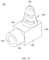
- FIG. 14 is a perspective view of a nozzle of the apparatus of FIG. 1 , in accordance with an aspect of the present invention.
- FIG. 15 is a first side view of the nozzle of FIG. 14 , in accordance with an aspect of the present invention.
- FIG. 16 is a second side view of a nozzle of FIG. 14 , in accordance with an aspect of the present invention.
- FIG. 17 is a first end view of the nozzle of FIG. 14 , in accordance with an aspect of the present invention.
- FIG. 18 is a second end view of the nozzle of FIG. 14 , in accordance with an aspect of the present invention.
- FIG. 19 is a top view of the nozzle of the apparatus of FIG. 14 , in accordance with an aspect of the present invention.
- FIG. 20 is a bottom view of the nozzle of FIG. 14 , in accordance with an aspect of the present invention.
- FIG. 21 is a cross-sectional view of the nozzle of FIG. 14 taken along line 21 - 21 of FIG. 19 , in accordance with an aspect of the present invention.
- FIG. 22 is a perspective view of the nozzle of FIG. 21 , in accordance with an aspect of the present invention.
- FIG. 23 is the first side view of FIG. 4 showing the dimensions of portions of the apparatus FIG. 1 , in accordance with an aspect of the present invention.
- FIG. 24 is a schematic depiction of a system including the apparatus of FIG. 1 , in accordance with an aspect of the present invention.
- an apparatus for recirculating fluids in the semiconductor industry Further, methods using the apparatus for recirculating fluids in the semiconductor industry are disclosed.
- the apparatus 100 may include a base portion 110 , an inlet portion 130 , a coupler 150 , and a nozzle member 180 .
- the inlet portion 130 may be coupled to a first end 112 of the base portion 110 by the coupler 150 .
- the nozzle member or nozzle portion 180 may be coupled to a second end 114 of the base portion 110 .
- the base portion 110 may include a first portion 116 , a second portion 118 and a connector 120 coupling the first portion 116 to the second portion 118 .
- the first portion 116 may be, for example, longer than the second portion 118 , as described in greater detail below with reference to FIG. 23 .
- the connector 120 may be, for example, angled to position the first portion 116 at an angle with respect to the second portion 118 .
- the inlet portion 130 may include a first end 132 and a second end 134 that is connected to the coupler 150 .
- the inlet portion 130 may also include a first portion 136 , a second portion 138 , and a connector 140 positioned between the first portion 136 and the second portion 138 .
- the connector 140 may, for example, have a diameter smaller than the diameter of the first portion 136 and the diameter of the second portion 138 .
- the first portion 136 may be secured to a recirculation system, as described in greater detail below with reference to FIG. 24 .
- the first portion 136 may be, for example, tapered from the first end 132 to the connector 140 .
- the second portion 138 may be received within a portion of the coupler 150 .
- the second portion 138 may have, for example, a uniform diameter along the entire length of the second portion 138 . Although not shown, in alternative embodiments, the second portion 138 may have, for example, different diameters or a varying diameter along the length of the second portion 138 .
- the coupler 150 may include a first end 152 and a second end 154 that is coupled to the first portion 116 of the base portion 110 .
- the coupler 150 may also include a first portion 156 , a second portion 158 , and a connector 160 positioned between the first portion 156 and the second portion 158 .
- the connector 160 may have a first outer diameter
- the first portion 156 may have a second outer diameter
- the second portion 158 may have a third outer diameter.
- the first outer diameter may be smaller than the third outer diameter and the second outer diameter may be larger than the first and third outer diameters.
- the first outer diameter of the connector 160 may be approximately the same size as the inner diameter of the interior engagement portions of the first portion 156 and the second portion 158 .
- the interior engagement portions allow for the connector 160 to be inserted within the passageway of the first portion 156 and the second portion 158 while aligning the passageway of the connector 160 with the passageways of the first portion 156 and second portion 158 .
- the first portion 156 couples to the first end 112 of the base portion 110 .
- the second portion 158 engages the first portion 116 of the base portion 110 at the first end 112 .
- the nozzle member 180 may include a first end 182 and a second end 184 .
- the nozzle member 180 may also include a base portion 186 , a nozzle portion 188 , and an inlet 194 .
- the nozzle portion 188 may, for example, extend away from the exterior surface of the base portion 186 between the first end 182 and the second end 184 of the nozzle member 180 .
- the nozzle portion 188 is positioned near the second end 184 of the base portion 186 .
- the nozzle portion 188 for example, tapers as it extends away from the base portion 186 to a tip 192 .
- the nozzle portion 188 includes a helical channel or groove 190 extending from a position near the base portion 186 to a position near the tip 192 of the nozzle portion 188 .
- the helical groove 190 extends from an exterior surface through the nozzle portion 188 to an interior surface.
- the nozzle member 180 may further include an opening 196 extending through the interior of the nozzle member 180 .
- the first end 182 of the nozzle member 180 may have an outer diameter sized to be received within the inner diameter of the second portion 118 at the second end 114 of the base portion 110 .
- the inner diameter of the second portion 118 may include an interior engagement portion for receiving the first end 182 of the nozzle member 180 to align the interior passageway 170 of the base portion 110 with the interior surface of the opening 196 .
- the inlet 194 engages the opening 196 extending through the base portion 186 .
- the opening 196 connects the inlet 194 to the helical groove 190 allowing fluid to mix as it passes through and out of the nozzle member 180 .
- the inlet 194 is aligned with and engages the passageway 170 to allow, for example, a slurry to pass through the inlet portion 130 , coupler 150 , and base portion 110 and into the nozzle member 180 .
- the nozzle portion 188 allows for, for example, an upward swirl of the slurry in a 360 degree or radial pattern.
- the upward swirl created by the nozzle portion 188 minimizes or eliminates the slurry shear caused by mixing or recirculating the slurry.
- the angle between the first portion 116 and second portion 118 of the base portion 110 may also minimize or eliminate the slurry shear caused by mixing or recirculating the slurry.
- the first portion 136 of the inlet portion 130 may also include a first tool engagement portion 210 with a first engagement edge 211 .
- the connector 120 may include a connector midpoint 200 .
- the apparatus 100 may include a first length l 1 extending between the first engagement edge 211 and the connector midpoint 200 .
- the first length l 1 may range between, for example, approximately twenty (20) inches and approximately forty (40) inches. More specifically, the first length l 1 may range between approximately twenty-two (22) inches and approximately thirty-eight (38) inches. In some embodiments, the first length l 1 may be approximately twenty-three (23) inches, approximately thirty-one (31) inches, approximately thirty-two (32) inches, approximately thirty-five (35) inches, or approximately thirty-seven (37) inches.
- the first portion 116 of the base portion 110 may include a second length l 2 .
- the second length l 2 may extend between the first end 112 of the base portion 110 and a second end 215 of the first portion 116 .
- the second length l 2 may range between, for example, approximately fifteen (15) inches and approximately thirty-five (35). More specifically, the second length l 2 may range between approximately sixteen (16) inches and approximately thirty-two (32) inches. Still more specifically, the second length l 2 may be approximately seventeen (17) inches, approximately twenty-five (25) inches, approximately twenty-six (26) inches, approximately twenty-eight (28) inches, or approximately thirty-one (31) inches.
- the ratio between the first length l 1 and the second length l 2 may range between, for example, approximately 1.1 to approximately 1.5. More specifically, the ratio between the first length l 1 and the second length l 2 (i.e., l 1 /l 2 ) may range between approximately 1.2 to approximately 1.4. Still more specifically, the ratio between the first length l 1 and the second length l 2 (i.e., l 1 /l 2 ) may be approximately 1.2, approximately 1.3, or approximately 1.4.
- the connector 120 may produce angle ⁇ between the first portion 116 and the second portion 118 .
- the angle ⁇ may range from, for example, approximately 90 degrees to approximately 160 degrees. More specifically, the angle ⁇ may range from, for example, approximately 120 degrees to approximately 150 degrees. Still more specifically, the angle ⁇ may be approximately 90 degrees, approximately 112 degrees, approximately 135 degrees, or approximately 157 degrees.
- the second portion 118 of the base portion 110 may include a second tool engagement portion 205 .
- the second tool engagement portion 205 may include a second engagement edge 206 .
- the apparatus 100 may include a third length l 3 extending between the second engagement edge 206 and the connector midpoint 200 .
- the third length l 3 may range between, for example, approximately two (2) inches and approximately four (4) inches. More specifically, the third length l 3 may be approximately two (2) inches, approximately 2.5 inches, approximately three (3) inches, approximately 3.5 inches, or approximately four (4) inches.
- a fourth length l 4 between the second end 184 of the nozzle portion 180 and the connector midpoint 200 is shown in FIG. 23 .
- the fourth length l 4 may range between, for example, approximately five (5) inches and approximately seven (7) inches. More specifically, the fourth length l 4 may be, for example, approximately five (5) inches, approximately 5.5 inches, approximately six (6) inches, approximately 6.5 inches, or approximately seven (7) inches.
- some or all components of the apparatus 100 may be partially or entirely made with fluoropolymers, such as, perfluoroalkoxy alkanes (PFA), polytetrafluoroethylene (PTFE), fluorinated ethylene propylene (FEP), or alternative materials with like properties.
- fluoropolymers such as, perfluoroalkoxy alkanes (PFA), polytetrafluoroethylene (PTFE), fluorinated ethylene propylene (FEP), or alternative materials with like properties.
- the components of the apparatus 100 may, for example, all be made of only one material, each be made of a different material, each be made of a combination of material, or each be made either of only one material or a combination of materials.
- a mixing system may include more than one the apparatus 100 .
- the mixing system may include a first apparatus 100 and a second apparatus 100 which each connect to an end of a recirculation line.
- the mixing system may include any number of apparatus 100 coupled to the end of the recirculation line.
- Each apparatus 100 in the mixing system may have the same or a different length to the remaining apparatus 100 .
- a method of recirculating fluids includes obtaining an apparatus 100 .
- the apparatus including a base portion 110 , an inlet portion 130 , a coupler 150 connecting the inlet portion 130 to the base portion 110 at a first end 112 , and a nozzle member 180 coupled to the base portion 110 at a second end 114 .
- the method may also include coupling the apparatus 100 to a recirculation system, such as shown in FIG. 24 .
- the method may further include passing a semiconductor slurry through the recirculation system and into a storage drum 300 .
- the recirculation system may include a recirculation loop 301 , which draws a slurry out of a storage drum 300 .
- the recirculation system may also include a pump 320 , a sample valve 310 , a rotameter 305 , and a pressure gauge 315 positioned along the recirculation loop 301 .
- the slurry may be drawn out of the storage drum 300 by the pump 320 .
- the slurry may then travel through the recirculation loop 301 and be deposited back into the storage drum 300 through apparatus 100 .
- the slurry health and thoroughness of mixing may be checked by periodic sampling of the recirculating slurry via the sample valve 310 positioned within the recirculation loop 301 .
- the volumetric flow rate may be monitored by a rotameter 305 positioned within the recirculation loop 301 .
- the flow pressure of the recirculation system may be monitored by a pressure gauge 315 , also positioned within the recirculation loop 301 .
- the apparatus 100 may include multiple second portions 118 each with a nozzle portion 180 to increase the mixing of the slurry.
- Slurry health refers to the physical properties of the particles in the raw slurry or blended slurry. These include the particle counts by size (i.e. 200 nm, 500 nm, 1 ⁇ , 5 ⁇ , etc.), along with particle distribution (number of each particles in the size buckets in comparison to the total number of particles per unit volume), D50 also known as the mean particle size, maximum particle size, amount & type of agglomerates, amount and type of aggregates, and a few others.
- CMP groups The majority of end users (CMP groups) find that practically, the particle size and distribution are the easiest to measure, and hence to correlate to defect in the wafer resulting from large particles, or too much fines (undersized particles), shifts in D50 or max particle size. These have been directly traced to defects in wafers and loss of revenue.
- the method of using the apparatus 100 utilizes the existing energy available in the recirculating raw slurry stream (as provided by the recirculating pump 320 ) to mix the slurry in order to reduce or virtually eliminate shearing of the particles (changing distribution and creating fine particles). Since the slurries in use are constantly changing to meet market demand (for example, the latest iPhones and Galaxy's) the number of particles per unit volume has risen from 2-3 million/cc to 5-6 million/cc. These are sometimes also known as nano-slurries. Thus, the method as described above is designed to maintain the supplier's initial size and distribution characteristics.
- the recirculation system with the apparatus 100 may be mounted on the top of a tank, for example, a 265 L tank with a conical bottom to maintain homogeneity.
- the tank may be, for example, a “day tank” from which other systems are fed the slurry.
- the apparatus 100 will assist with continuing to mix the slurry to maintain a homogeneous state of the slurry while in the “day tank.”
- a “day tank” the length of the first portion 116 of the apparatus 100 may vary based on the size of the tank.
- the length of the second portion 118 of the apparatus 100 may also vary based on the size of the tank. For example, the larger the tank the longer the first portion 116 and the second portion 118 may be.
- the recirculation system with at least one apparatus 100 may be mounted on top of a “day tank” which may be, for example, at least a 500 L tank with a conical bottom unit.
- the at least one apparatus 100 will assist with continuing to mix the slurry to maintain a homogeneous state of the slurry while in the “day tank.”
- the method of using at least one apparatus 100 mounted on the top of a “day tank” may include mixing in additional drums of slurry to the large tank to maintain a desired level in the tank.
- the at least one apparatus 100 allows for the new slurry to be mixed with the existing slurry to spread any minor variations between drums of slurry over a larger volume to significantly reduce the risk of dramatic changes in material, for example, particle size distribution, pH, density, and the like.
- the incorporation of any variations throughout the larger volume may allow for defects to be avoided or in the worst case make the issue minor enough that the wafer can be saved through a re-working process.
- the method of using a larger tank may include inserting more than one apparatus 100 into the tank in order to maintain the mixing in the larger tank.
- the recirculation line may be split and couple to two apparatus 100 providing for two nozzles 188 .
- the two nozzles 188 may be, for example, spaced 180° apart in order to maintain the mixing in the larger tank.
- the length of the two apparatus 100 may, for example, vary with one apparatus 100 being longer than the second apparatus 100 .
- the method may include using both nozzles 188 when the tank is full and then turning off flow to at least one of the two nozzles 188 when the level of slurry in the tank drops below a specified level.
- the ability to adjust the number of nozzles 188 which the slurry is flowing through based on the level of slurry in the tank allows the user to avoid over mixing the slurry and preserve slurry health.
- more than two apparatus 100 may be included to achieve the necessary mixing.
- the nozzles 188 may be, for example, radially spaced around the tank to achieve the maximum effect and desired mixing.
- the lengths of some of the apparatus 100 or all of the apparatus 100 may vary to allow for nozzles 188 to be turned off depending on the level of slurry in the tank.
- a method or device that “comprises,” “has,” “includes,” or “contains” one or more steps or elements possesses those one or more steps or elements, but is not limited to possessing only those one or more steps or elements.
- a step of a method or an element of a device that “comprises,” “has,” “includes,” or “contains” one or more features possesses those one or more features, but is not limited to possessing only those one or more features.
- a device or structure that is configured in a certain way is configured in at least that way, but may also be configured in ways that are not listed.
Abstract
Description
Claims (12)
Priority Applications (1)
| Application Number | Priority Date | Filing Date | Title |
|---|---|---|---|
| US16/723,547 US11858091B2 (en) | 2018-11-30 | 2019-12-20 | Apparatus and method for recirculating fluids |
Applications Claiming Priority (4)
| Application Number | Priority Date | Filing Date | Title |
|---|---|---|---|
| US201862774156P | 2018-11-30 | 2018-11-30 | |
| US201962892847P | 2019-08-28 | 2019-08-28 | |
| PCT/US2019/063266 WO2020112784A1 (en) | 2018-11-30 | 2019-11-26 | Apparatus and method for recirculating fluids |
| US16/723,547 US11858091B2 (en) | 2018-11-30 | 2019-12-20 | Apparatus and method for recirculating fluids |
Related Parent Applications (1)
| Application Number | Title | Priority Date | Filing Date |
|---|---|---|---|
| PCT/US2019/063266 Continuation WO2020112784A1 (en) | 2018-11-30 | 2019-11-26 | Apparatus and method for recirculating fluids |
Publications (2)
| Publication Number | Publication Date |
|---|---|
| US20200171622A1 US20200171622A1 (en) | 2020-06-04 |
| US11858091B2 true US11858091B2 (en) | 2024-01-02 |
Family
ID=70851101
Family Applications (1)
| Application Number | Title | Priority Date | Filing Date |
|---|---|---|---|
| US16/723,547 Active 2040-10-01 US11858091B2 (en) | 2018-11-30 | 2019-12-20 | Apparatus and method for recirculating fluids |
Country Status (1)
| Country | Link |
|---|---|
| US (1) | US11858091B2 (en) |
Citations (15)
| Publication number | Priority date | Publication date | Assignee | Title |
|---|---|---|---|---|
| US4239512A (en) * | 1977-07-21 | 1980-12-16 | Binks Manufacturing Company | Air washer particularly for paint spray booths |
| US4421874A (en) | 1981-06-02 | 1983-12-20 | Phillips Petroleum Company | Polymer slurry washing |
| US5129956A (en) | 1989-10-06 | 1992-07-14 | Digital Equipment Corporation | Method and apparatus for the aqueous cleaning of populated printed circuit boards |
| JPH07103865A (en) | 1993-09-30 | 1995-04-21 | Ket Kagaku Kenkyusho:Kk | Sampler for slurry concentration measuring device |
| EP0984166A1 (en) * | 1998-09-02 | 2000-03-08 | Giw Industries Inc. | High capacity slurry pump |
| US20020006876A1 (en) | 2000-04-27 | 2002-01-17 | Akihisa Hongo | Revolution member supporting apparatus and semiconductor substrate processing apparatus |
| CN2561501Y (en) | 2002-08-06 | 2003-07-23 | 深圳市清泉水系统工程设备有限公司 | Dissolving mixers |
| TW200507941A (en) | 2003-06-12 | 2005-03-01 | Ishikawajima Harima Heavy Ind | Spiral nozzle |
| US20050145166A1 (en) | 2002-09-13 | 2005-07-07 | Towa Intercon Tools, Inc. | Jet singulation |
| TWM282740U (en) | 2005-07-13 | 2005-12-11 | King Roof Ind Co Ltd | Nozzle apparatus |
| US20070144602A1 (en) | 2005-12-27 | 2007-06-28 | Henkin Melvyn L | Automatic pool cleaner power conduit including stiff sections and resilient axially flexible couplers |
| US20100224256A1 (en) * | 2009-03-04 | 2010-09-09 | Taiwan Semiconductor Manufacturing Co., Ltd. | Slurry system for semiconductor fabrication |
| CN201992249U (en) | 2011-01-25 | 2011-09-28 | 长沙中联重工科技发展股份有限公司 | Reducing elbow and pumping equipment comprising same |
| US20120216840A1 (en) | 2009-11-03 | 2012-08-30 | Arakawa Chemical Industries, Ltd. | Electronic component cleaning device and cleaning method |
| US20130109612A1 (en) * | 2011-10-28 | 2013-05-02 | The Procter & Gamble Company | Fabric care compositions |
-
2019
- 2019-12-20 US US16/723,547 patent/US11858091B2/en active Active
Patent Citations (15)
| Publication number | Priority date | Publication date | Assignee | Title |
|---|---|---|---|---|
| US4239512A (en) * | 1977-07-21 | 1980-12-16 | Binks Manufacturing Company | Air washer particularly for paint spray booths |
| US4421874A (en) | 1981-06-02 | 1983-12-20 | Phillips Petroleum Company | Polymer slurry washing |
| US5129956A (en) | 1989-10-06 | 1992-07-14 | Digital Equipment Corporation | Method and apparatus for the aqueous cleaning of populated printed circuit boards |
| JPH07103865A (en) | 1993-09-30 | 1995-04-21 | Ket Kagaku Kenkyusho:Kk | Sampler for slurry concentration measuring device |
| EP0984166A1 (en) * | 1998-09-02 | 2000-03-08 | Giw Industries Inc. | High capacity slurry pump |
| US20020006876A1 (en) | 2000-04-27 | 2002-01-17 | Akihisa Hongo | Revolution member supporting apparatus and semiconductor substrate processing apparatus |
| CN2561501Y (en) | 2002-08-06 | 2003-07-23 | 深圳市清泉水系统工程设备有限公司 | Dissolving mixers |
| US20050145166A1 (en) | 2002-09-13 | 2005-07-07 | Towa Intercon Tools, Inc. | Jet singulation |
| TW200507941A (en) | 2003-06-12 | 2005-03-01 | Ishikawajima Harima Heavy Ind | Spiral nozzle |
| TWM282740U (en) | 2005-07-13 | 2005-12-11 | King Roof Ind Co Ltd | Nozzle apparatus |
| US20070144602A1 (en) | 2005-12-27 | 2007-06-28 | Henkin Melvyn L | Automatic pool cleaner power conduit including stiff sections and resilient axially flexible couplers |
| US20100224256A1 (en) * | 2009-03-04 | 2010-09-09 | Taiwan Semiconductor Manufacturing Co., Ltd. | Slurry system for semiconductor fabrication |
| US20120216840A1 (en) | 2009-11-03 | 2012-08-30 | Arakawa Chemical Industries, Ltd. | Electronic component cleaning device and cleaning method |
| CN201992249U (en) | 2011-01-25 | 2011-09-28 | 长沙中联重工科技发展股份有限公司 | Reducing elbow and pumping equipment comprising same |
| US20130109612A1 (en) * | 2011-10-28 | 2013-05-02 | The Procter & Gamble Company | Fabric care compositions |
Non-Patent Citations (1)
| Title |
|---|
| International Search Report and Written Opinion of the International Searching Authority for PCT/US2019/063266, dated Mar. 25, 2020, 13 pages. |
Also Published As
| Publication number | Publication date |
|---|---|
| US20200171622A1 (en) | 2020-06-04 |
Similar Documents
| Publication | Publication Date | Title |
|---|---|---|
| US6796704B1 (en) | Apparatus and method for mixing components with a venturi arrangement | |
| DE60123967T2 (en) | VORTEX REDUCING CONNECTION | |
| US20030081493A1 (en) | Cement mixing system for oil well cementing | |
| US5590960A (en) | One tank paint makeup process using a recirculation loop with liquid injection | |
| US20120307588A1 (en) | In-line-type fluid mixer | |
| CN1446117A (en) | Method and apparatus for blending process materials | |
| EP1819429A1 (en) | Dry polymer hydration apparatus and methods of use | |
| CN106422955B (en) | It is a kind of quickly, the device and method of a large amount of, continuous production nanoemulsions or nano suspending liquid | |
| US11858091B2 (en) | Apparatus and method for recirculating fluids | |
| US20210046434A1 (en) | Apparatus for dispersing particles in a liquid | |
| US5183335A (en) | Hydraulic jet flash mixer with flow deflector | |
| CN106215733B (en) | A kind of pressure break powder liquid blending device | |
| US4860959A (en) | Apparatus for subjecting particles dispersed in a fluid to a shearing action | |
| EP1025896A1 (en) | Apparatus and method for mixing | |
| WO2020112784A1 (en) | Apparatus and method for recirculating fluids | |
| US11084010B2 (en) | Temperature conditioned two component mixer manifold | |
| US11097231B2 (en) | High-capacity polymer system and method of preparing polymeric mixtures | |
| EP0299722A2 (en) | Improved dissolution performance by injection through a die- type nozzle | |
| EP3253480A1 (en) | Mixing device with integrated delivery pump | |
| US6394642B2 (en) | Mixing reservoir for an automated recirculating particle size analysis method | |
| CN1713967B (en) | Chemical-solution supplying apparatus | |
| EP1892032A1 (en) | Mixing device for liquids | |
| US5347868A (en) | Pressure gauge for thixotropic liquids | |
| CN215963320U (en) | Mixing system | |
| AU657077B2 (en) | Fluid integrator |
Legal Events
| Date | Code | Title | Description |
|---|---|---|---|
| FEPP | Fee payment procedure |
Free format text: ENTITY STATUS SET TO UNDISCOUNTED (ORIGINAL EVENT CODE: BIG.); ENTITY STATUS OF PATENT OWNER: LARGE ENTITY |
|
| FEPP | Fee payment procedure |
Free format text: ENTITY STATUS SET TO SMALL (ORIGINAL EVENT CODE: SMAL); ENTITY STATUS OF PATENT OWNER: LARGE ENTITY |
|
| STPP | Information on status: patent application and granting procedure in general |
Free format text: DOCKETED NEW CASE - READY FOR EXAMINATION |
|
| STPP | Information on status: patent application and granting procedure in general |
Free format text: NON FINAL ACTION MAILED |
|
| STPP | Information on status: patent application and granting procedure in general |
Free format text: RESPONSE TO NON-FINAL OFFICE ACTION ENTERED AND FORWARDED TO EXAMINER |
|
| STPP | Information on status: patent application and granting procedure in general |
Free format text: FINAL REJECTION MAILED |
|
| FEPP | Fee payment procedure |
Free format text: ENTITY STATUS SET TO UNDISCOUNTED (ORIGINAL EVENT CODE: BIG.); ENTITY STATUS OF PATENT OWNER: LARGE ENTITY |
|
| STPP | Information on status: patent application and granting procedure in general |
Free format text: NOTICE OF ALLOWANCE MAILED -- APPLICATION RECEIVED IN OFFICE OF PUBLICATIONS |
|
| STPP | Information on status: patent application and granting procedure in general |
Free format text: PUBLICATIONS -- ISSUE FEE PAYMENT VERIFIED |
|
| STCF | Information on status: patent grant |
Free format text: PATENTED CASE |