US11856993B2 - Aerosol-generating system comprising a fluid permeable susceptor element - Google Patents
Aerosol-generating system comprising a fluid permeable susceptor element Download PDFInfo
- Publication number
- US11856993B2 US11856993B2 US18/174,171 US202318174171A US11856993B2 US 11856993 B2 US11856993 B2 US 11856993B2 US 202318174171 A US202318174171 A US 202318174171A US 11856993 B2 US11856993 B2 US 11856993B2
- Authority
- US
- United States
- Prior art keywords
- aerosol
- cartridge
- susceptor element
- inductor coil
- housing
- Prior art date
- Legal status (The legal status is an assumption and is not a legal conclusion. Google has not performed a legal analysis and makes no representation as to the accuracy of the status listed.)
- Active
Links
- 239000012530 fluid Substances 0.000 title claims abstract description 17
- 239000000463 material Substances 0.000 claims abstract description 84
- 239000000758 substrate Substances 0.000 claims abstract description 58
- 238000005979 thermal decomposition reaction Methods 0.000 claims abstract description 6
- 239000007788 liquid Substances 0.000 claims description 24
- 239000000443 aerosol Substances 0.000 claims description 17
- 230000000391 smoking effect Effects 0.000 claims description 6
- 239000004744 fabric Substances 0.000 claims description 3
- 238000010438 heat treatment Methods 0.000 description 22
- 230000005291 magnetic effect Effects 0.000 description 14
- 230000001939 inductive effect Effects 0.000 description 9
- PEDCQBHIVMGVHV-UHFFFAOYSA-N Glycerine Chemical compound OCC(O)CO PEDCQBHIVMGVHV-UHFFFAOYSA-N 0.000 description 7
- 230000008901 benefit Effects 0.000 description 7
- 239000003990 capacitor Substances 0.000 description 7
- 238000001514 detection method Methods 0.000 description 7
- 239000010753 BS 2869 Class E Substances 0.000 description 6
- 230000005294 ferromagnetic effect Effects 0.000 description 6
- 230000007246 mechanism Effects 0.000 description 6
- 229910000859 α-Fe Inorganic materials 0.000 description 6
- 241000208125 Nicotiana Species 0.000 description 5
- 235000002637 Nicotiana tabacum Nutrition 0.000 description 5
- 150000001875 compounds Chemical class 0.000 description 5
- PUPZLCDOIYMWBV-UHFFFAOYSA-N (+/-)-1,3-Butanediol Chemical compound CC(O)CCO PUPZLCDOIYMWBV-UHFFFAOYSA-N 0.000 description 4
- 230000035699 permeability Effects 0.000 description 4
- OKTJSMMVPCPJKN-UHFFFAOYSA-N Carbon Chemical compound [C] OKTJSMMVPCPJKN-UHFFFAOYSA-N 0.000 description 3
- 239000003571 electronic cigarette Substances 0.000 description 3
- 235000011187 glycerol Nutrition 0.000 description 3
- 229910002804 graphite Inorganic materials 0.000 description 3
- 239000010439 graphite Substances 0.000 description 3
- 239000012466 permeate Substances 0.000 description 3
- -1 polyethylene Polymers 0.000 description 3
- 239000005020 polyethylene terephthalate Substances 0.000 description 3
- 150000005846 sugar alcohols Polymers 0.000 description 3
- 230000007704 transition Effects 0.000 description 3
- 239000010752 BS 2869 Class D Substances 0.000 description 2
- 241000196324 Embryophyta Species 0.000 description 2
- 229910000831 Steel Inorganic materials 0.000 description 2
- 230000009471 action Effects 0.000 description 2
- 230000004913 activation Effects 0.000 description 2
- 238000001994 activation Methods 0.000 description 2
- 230000008859 change Effects 0.000 description 2
- 235000019504 cigarettes Nutrition 0.000 description 2
- 238000010276 construction Methods 0.000 description 2
- 230000007797 corrosion Effects 0.000 description 2
- 238000005260 corrosion Methods 0.000 description 2
- ZDJFDFNNEAPGOP-UHFFFAOYSA-N dimethyl tetradecanedioate Chemical compound COC(=O)CCCCCCCCCCCCC(=O)OC ZDJFDFNNEAPGOP-UHFFFAOYSA-N 0.000 description 2
- 239000011152 fibreglass Substances 0.000 description 2
- 230000005669 field effect Effects 0.000 description 2
- 239000000796 flavoring agent Substances 0.000 description 2
- 239000007792 gaseous phase Substances 0.000 description 2
- 230000020169 heat generation Effects 0.000 description 2
- 229920001903 high density polyethylene Polymers 0.000 description 2
- 239000004700 high-density polyethylene Substances 0.000 description 2
- GELKBWJHTRAYNV-UHFFFAOYSA-K lithium iron phosphate Chemical compound [Li+].[Fe+2].[O-]P([O-])([O-])=O GELKBWJHTRAYNV-UHFFFAOYSA-K 0.000 description 2
- 230000005499 meniscus Effects 0.000 description 2
- 239000000203 mixture Substances 0.000 description 2
- 230000005298 paramagnetic effect Effects 0.000 description 2
- 230000000704 physical effect Effects 0.000 description 2
- 229920000139 polyethylene terephthalate Polymers 0.000 description 2
- 239000000047 product Substances 0.000 description 2
- 239000007787 solid Substances 0.000 description 2
- 125000006850 spacer group Chemical group 0.000 description 2
- 239000010959 steel Substances 0.000 description 2
- ZIBGPFATKBEMQZ-UHFFFAOYSA-N triethylene glycol Chemical compound OCCOCCOCCO ZIBGPFATKBEMQZ-UHFFFAOYSA-N 0.000 description 2
- RYGMFSIKBFXOCR-UHFFFAOYSA-N Copper Chemical compound [Cu] RYGMFSIKBFXOCR-UHFFFAOYSA-N 0.000 description 1
- ZOKXTWBITQBERF-UHFFFAOYSA-N Molybdenum Chemical compound [Mo] ZOKXTWBITQBERF-UHFFFAOYSA-N 0.000 description 1
- 239000004677 Nylon Substances 0.000 description 1
- 239000004698 Polyethylene Substances 0.000 description 1
- 239000004743 Polypropylene Substances 0.000 description 1
- 229920004933 Terylene® Polymers 0.000 description 1
- 239000002253 acid Substances 0.000 description 1
- 150000007513 acids Chemical class 0.000 description 1
- 239000000654 additive Substances 0.000 description 1
- 239000002386 air freshener Substances 0.000 description 1
- 125000001931 aliphatic group Chemical group 0.000 description 1
- 239000004411 aluminium Substances 0.000 description 1
- 229910052782 aluminium Inorganic materials 0.000 description 1
- XAGFODPZIPBFFR-UHFFFAOYSA-N aluminium Chemical compound [Al] XAGFODPZIPBFFR-UHFFFAOYSA-N 0.000 description 1
- 230000015572 biosynthetic process Effects 0.000 description 1
- 238000009835 boiling Methods 0.000 description 1
- 230000015556 catabolic process Effects 0.000 description 1
- 229920002301 cellulose acetate Polymers 0.000 description 1
- 239000000919 ceramic Substances 0.000 description 1
- 235000019506 cigar Nutrition 0.000 description 1
- 239000011248 coating agent Substances 0.000 description 1
- 238000000576 coating method Methods 0.000 description 1
- 238000001816 cooling Methods 0.000 description 1
- 229910052802 copper Inorganic materials 0.000 description 1
- 239000010949 copper Substances 0.000 description 1
- 230000008878 coupling Effects 0.000 description 1
- 238000010168 coupling process Methods 0.000 description 1
- 238000005859 coupling reaction Methods 0.000 description 1
- 238000006731 degradation reaction Methods 0.000 description 1
- 230000003111 delayed effect Effects 0.000 description 1
- IZMOTZDBVPMOFE-UHFFFAOYSA-N dimethyl dodecanedioate Chemical compound COC(=O)CCCCCCCCCCC(=O)OC IZMOTZDBVPMOFE-UHFFFAOYSA-N 0.000 description 1
- 239000003814 drug Substances 0.000 description 1
- 229940079593 drug Drugs 0.000 description 1
- 230000003670 easy-to-clean Effects 0.000 description 1
- 230000000694 effects Effects 0.000 description 1
- 150000002148 esters Chemical class 0.000 description 1
- 239000002657 fibrous material Substances 0.000 description 1
- 235000019634 flavors Nutrition 0.000 description 1
- 239000006261 foam material Substances 0.000 description 1
- 239000011888 foil Substances 0.000 description 1
- 239000007789 gas Substances 0.000 description 1
- 239000004615 ingredient Substances 0.000 description 1
- 239000007791 liquid phase Substances 0.000 description 1
- 230000005381 magnetic domain Effects 0.000 description 1
- 238000004519 manufacturing process Methods 0.000 description 1
- 229910052751 metal Inorganic materials 0.000 description 1
- 239000002184 metal Substances 0.000 description 1
- 229910052750 molybdenum Inorganic materials 0.000 description 1
- 239000011733 molybdenum Substances 0.000 description 1
- 239000010955 niobium Substances 0.000 description 1
- 229910052758 niobium Inorganic materials 0.000 description 1
- GUCVJGMIXFAOAE-UHFFFAOYSA-N niobium atom Chemical compound [Nb] GUCVJGMIXFAOAE-UHFFFAOYSA-N 0.000 description 1
- 229920001778 nylon Polymers 0.000 description 1
- 238000013021 overheating Methods 0.000 description 1
- 230000021715 photosynthesis, light harvesting Effects 0.000 description 1
- 239000004033 plastic Substances 0.000 description 1
- 229920003023 plastic Polymers 0.000 description 1
- 229920000728 polyester Polymers 0.000 description 1
- 229920000573 polyethylene Polymers 0.000 description 1
- 229920000642 polymer Polymers 0.000 description 1
- 229920000098 polyolefin Polymers 0.000 description 1
- 229920001155 polypropylene Polymers 0.000 description 1
- 239000000843 powder Substances 0.000 description 1
- 238000010248 power generation Methods 0.000 description 1
- 230000001681 protective effect Effects 0.000 description 1
- 230000005855 radiation Effects 0.000 description 1
- 239000004065 semiconductor Substances 0.000 description 1
- HBMJWWWQQXIZIP-UHFFFAOYSA-N silicon carbide Chemical compound [Si+]#[C-] HBMJWWWQQXIZIP-UHFFFAOYSA-N 0.000 description 1
- 229910010271 silicon carbide Inorganic materials 0.000 description 1
- 239000000779 smoke Substances 0.000 description 1
- 229910000679 solder Inorganic materials 0.000 description 1
- 229910001220 stainless steel Inorganic materials 0.000 description 1
- ILJSQTXMGCGYMG-UHFFFAOYSA-N triacetic acid Chemical compound CC(=O)CC(=O)CC(O)=O ILJSQTXMGCGYMG-UHFFFAOYSA-N 0.000 description 1
- 238000004804 winding Methods 0.000 description 1
Images


Classifications
-
- A—HUMAN NECESSITIES
- A24—TOBACCO; CIGARS; CIGARETTES; SIMULATED SMOKING DEVICES; SMOKERS' REQUISITES
- A24F—SMOKERS' REQUISITES; MATCH BOXES; SIMULATED SMOKING DEVICES
- A24F40/00—Electrically operated smoking devices; Component parts thereof; Manufacture thereof; Maintenance or testing thereof; Charging means specially adapted therefor
- A24F40/40—Constructional details, e.g. connection of cartridges and battery parts
- A24F40/46—Shape or structure of electric heating means
- A24F40/465—Shape or structure of electric heating means specially adapted for induction heating
-
- A—HUMAN NECESSITIES
- A24—TOBACCO; CIGARS; CIGARETTES; SIMULATED SMOKING DEVICES; SMOKERS' REQUISITES
- A24B—MANUFACTURE OR PREPARATION OF TOBACCO FOR SMOKING OR CHEWING; TOBACCO; SNUFF
- A24B15/00—Chemical features or treatment of tobacco; Tobacco substitutes, e.g. in liquid form
- A24B15/10—Chemical features of tobacco products or tobacco substitutes
- A24B15/16—Chemical features of tobacco products or tobacco substitutes of tobacco substitutes
- A24B15/167—Chemical features of tobacco products or tobacco substitutes of tobacco substitutes in liquid or vaporisable form, e.g. liquid compositions for electronic cigarettes
-
- A—HUMAN NECESSITIES
- A24—TOBACCO; CIGARS; CIGARETTES; SIMULATED SMOKING DEVICES; SMOKERS' REQUISITES
- A24F—SMOKERS' REQUISITES; MATCH BOXES; SIMULATED SMOKING DEVICES
- A24F40/00—Electrically operated smoking devices; Component parts thereof; Manufacture thereof; Maintenance or testing thereof; Charging means specially adapted therefor
- A24F40/40—Constructional details, e.g. connection of cartridges and battery parts
- A24F40/42—Cartridges or containers for inhalable precursors
-
- A—HUMAN NECESSITIES
- A24—TOBACCO; CIGARS; CIGARETTES; SIMULATED SMOKING DEVICES; SMOKERS' REQUISITES
- A24F—SMOKERS' REQUISITES; MATCH BOXES; SIMULATED SMOKING DEVICES
- A24F40/00—Electrically operated smoking devices; Component parts thereof; Manufacture thereof; Maintenance or testing thereof; Charging means specially adapted therefor
- A24F40/85—Maintenance, e.g. cleaning
-
- A—HUMAN NECESSITIES
- A24—TOBACCO; CIGARS; CIGARETTES; SIMULATED SMOKING DEVICES; SMOKERS' REQUISITES
- A24F—SMOKERS' REQUISITES; MATCH BOXES; SIMULATED SMOKING DEVICES
- A24F40/00—Electrically operated smoking devices; Component parts thereof; Manufacture thereof; Maintenance or testing thereof; Charging means specially adapted therefor
- A24F40/90—Arrangements or methods specially adapted for charging batteries thereof
-
- A—HUMAN NECESSITIES
- A24—TOBACCO; CIGARS; CIGARETTES; SIMULATED SMOKING DEVICES; SMOKERS' REQUISITES
- A24F—SMOKERS' REQUISITES; MATCH BOXES; SIMULATED SMOKING DEVICES
- A24F7/00—Mouthpieces for pipes; Mouthpieces for cigar or cigarette holders
-
- A—HUMAN NECESSITIES
- A61—MEDICAL OR VETERINARY SCIENCE; HYGIENE
- A61M—DEVICES FOR INTRODUCING MEDIA INTO, OR ONTO, THE BODY; DEVICES FOR TRANSDUCING BODY MEDIA OR FOR TAKING MEDIA FROM THE BODY; DEVICES FOR PRODUCING OR ENDING SLEEP OR STUPOR
- A61M15/00—Inhalators
- A61M15/06—Inhaling appliances shaped like cigars, cigarettes or pipes
-
- H—ELECTRICITY
- H05—ELECTRIC TECHNIQUES NOT OTHERWISE PROVIDED FOR
- H05B—ELECTRIC HEATING; ELECTRIC LIGHT SOURCES NOT OTHERWISE PROVIDED FOR; CIRCUIT ARRANGEMENTS FOR ELECTRIC LIGHT SOURCES, IN GENERAL
- H05B6/00—Heating by electric, magnetic or electromagnetic fields
- H05B6/02—Induction heating
- H05B6/10—Induction heating apparatus, other than furnaces, for specific applications
- H05B6/105—Induction heating apparatus, other than furnaces, for specific applications using a susceptor
- H05B6/108—Induction heating apparatus, other than furnaces, for specific applications using a susceptor for heating a fluid
-
- H—ELECTRICITY
- H05—ELECTRIC TECHNIQUES NOT OTHERWISE PROVIDED FOR
- H05B—ELECTRIC HEATING; ELECTRIC LIGHT SOURCES NOT OTHERWISE PROVIDED FOR; CIRCUIT ARRANGEMENTS FOR ELECTRIC LIGHT SOURCES, IN GENERAL
- H05B6/00—Heating by electric, magnetic or electromagnetic fields
- H05B6/02—Induction heating
- H05B6/36—Coil arrangements
- H05B6/362—Coil arrangements with flat coil conductors
-
- H—ELECTRICITY
- H05—ELECTRIC TECHNIQUES NOT OTHERWISE PROVIDED FOR
- H05B—ELECTRIC HEATING; ELECTRIC LIGHT SOURCES NOT OTHERWISE PROVIDED FOR; CIRCUIT ARRANGEMENTS FOR ELECTRIC LIGHT SOURCES, IN GENERAL
- H05B6/00—Heating by electric, magnetic or electromagnetic fields
- H05B6/02—Induction heating
- H05B6/36—Coil arrangements
- H05B6/38—Coil arrangements specially adapted for fitting into hollow spaces of workpieces
-
- A—HUMAN NECESSITIES
- A24—TOBACCO; CIGARS; CIGARETTES; SIMULATED SMOKING DEVICES; SMOKERS' REQUISITES
- A24F—SMOKERS' REQUISITES; MATCH BOXES; SIMULATED SMOKING DEVICES
- A24F40/00—Electrically operated smoking devices; Component parts thereof; Manufacture thereof; Maintenance or testing thereof; Charging means specially adapted therefor
- A24F40/10—Devices using liquid inhalable precursors
-
- A—HUMAN NECESSITIES
- A24—TOBACCO; CIGARS; CIGARETTES; SIMULATED SMOKING DEVICES; SMOKERS' REQUISITES
- A24F—SMOKERS' REQUISITES; MATCH BOXES; SIMULATED SMOKING DEVICES
- A24F40/00—Electrically operated smoking devices; Component parts thereof; Manufacture thereof; Maintenance or testing thereof; Charging means specially adapted therefor
- A24F40/40—Constructional details, e.g. connection of cartridges and battery parts
- A24F40/44—Wicks
-
- A—HUMAN NECESSITIES
- A61—MEDICAL OR VETERINARY SCIENCE; HYGIENE
- A61M—DEVICES FOR INTRODUCING MEDIA INTO, OR ONTO, THE BODY; DEVICES FOR TRANSDUCING BODY MEDIA OR FOR TAKING MEDIA FROM THE BODY; DEVICES FOR PRODUCING OR ENDING SLEEP OR STUPOR
- A61M2205/00—General characteristics of the apparatus
- A61M2205/82—Internal energy supply devices
- A61M2205/8206—Internal energy supply devices battery-operated
Definitions
- the disclosure relates to aerosol-generating systems that operate by heating an aerosol-forming substrate.
- the invention relates to aerosol-generating systems that comprise a device portion containing a power supply and a replaceable cartridge portion comprising the consumable aerosol-forming substrate.
- One type of aerosol-generating system is an electronic cigarette.
- Electronic cigarettes typically use a liquid aerosol-forming substrate which is vapourised to form an aerosol.
- An electronic cigarette typically comprises a power supply, a liquid storage portion for holding a supply of the liquid aerosol-forming substrate and an atomiser.
- a cartomiser comprises both a supply of liquid substrate and the atomiser, usually in the form of an electrically operated resistance heater wound around a capillary material soaked in the aerosol-forming substrate. Replacing a cartomiser as a single unit has the benefit of being convenient for the user and avoids the need for the user to have to clean or otherwise maintain the atomiser.
- an electrically heated aerosol-generating system comprising an aerosol-generating device and a cartridge configured to be used with the device, the device comprising: a device housing; an inductor coil positioned around or adjacent to the cavity; and a power supply connected to the inductor coil and configured to provide a high frequency oscillating current to the inductor coil; the cartridge comprising: a cartridge housing configured to engage the device housing and containing an aerosol-forming substrate, the housing having an external surface surrounding the aerosol-forming substrate, at least a portion of the external surface being formed by a fluid permeable susceptor element.
- a cartridge for use in an electrically heated aerosol-generating system comprising an aerosol-generating device, the cartridge configured to be used with the device, wherein the device comprises a device housing defining a cavity for receiving at least a portion of the cartridge; an inductor coil positioned around or adjacent to the cavity; and a power supply connected to the inductor coil and configured to provide a high frequency oscillating current to the inductor coil; the cartridge comprising a cartridge housing containing an aerosol-forming substrate, the housing having an external surface, at least a portion of the external surface being formed by a fluid permeable susceptor element, wherein the susceptor element is electrically isolated from any other electrically conductive components.
- FIG. 1 is a schematic illustration of a first embodiment of an aerosol-generating system, using a flat spiral inductor coil;
- FIG. 2 shows the cartridge of FIG. 1 ;
- FIG. 3 shows the inductor coil of FIG. 1 ;
- FIG. 4 shows an alternative susceptor element for the cartridge of FIG. 2 ;
- FIG. 5 shows a further alternative susceptor element for the cartridge of FIG. 1 ;
- FIG. 6 is a schematic illustration of a second embodiment, using a flat spiral inductor coil
- FIG. 7 is a schematic illustration of a third embodiment, using flat spiral inductor coils
- FIG. 8 shows the cartridge of FIG. 7 ;
- FIG. 9 shows the inductor coil of FIG. 7 ;
- FIG. 10 is a schematic illustration of a fourth embodiment
- FIG. 11 shows the cartridge of FIG. 10 ;
- FIG. 12 shows the coil of FIG. 10 ;
- FIG. 13 is a schematic illustration of a fifth embodiment
- FIG. 14 is a schematic illustration of a sixth embodiment
- FIG. 15 is a schematic illustration of an eighth embodiment, using a unit dose cartridge
- FIG. 16 A is a first example of a driving circuit for generating the high frequency signal for an inductor coil
- FIG. 16 B is a second example of a driving circuit for generating the high frequency signal for an inductor coil.
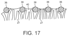
- FIG. 17 is a schematic illustration showing a portion of the cartridge of FIG. 2 .
- a high frequency oscillating current is passed through the flat spiral inductor coil to generate an alternating magnetic field that induces a voltage in the susceptor element.
- the induced voltage causes a current to flow in the susceptor element and this current causes Joule heating of the susceptor that in turn heats the aerosol-forming substrate. If the susceptor element is ferromagnetic, hysteresis losses in the susceptor element may also generate heat.
- the vapourised aerosol-forming substrate can pass through the susceptor element and subsequently cool to form an aerosol delivered to a user.
- This arrangement using inductive heating has the advantage that no electrical contacts need be formed between the cartridge and the device. And the heating element, in this case the susceptor element, need not be electrically joined to any other components, eliminating the need for solder or other bonding elements. Furthermore, the coil is provided as part of the device making it possible to construct a cartridge that is simple, inexpensive and robust. Cartridges are typically disposable articles produced in much larger numbers than the devices with which they operate. Accordingly reducing the cost of cartridges, even if it requires a more expensive device, can lead to significant cost savings for both manufacturers and consumers.
- a high frequency oscillating current means an oscillating current having a frequency of between 500 kHz and 30 MHz.
- the high frequency oscillating current may have a frequency of between 1 and 30 MHz, preferably between 1 and 10 MHz and more preferably between 5 and 7 MHz.
- a “susceptor element” means a conductive element that heats up when subjected to a changing magnetic field. This may be the result of eddy currents induced in the susceptor element and/or hysteresis losses.
- Possible materials for the susceptor elements include graphite, molybdenum, silicon carbide, stainless steels, niobium, aluminium and virtually any other conductive elements.
- the susceptor element is a ferrite element.
- the material and the geometry for the susceptor element can be chosen to provide a desired electrical resistance and heat generation.
- the susceptor element may comprise, for example, a mesh, flat spiral coil, fibres or a fabric.
- a “fluid permeable” element means an element that allowing liquid or gas to permeate through it.
- the susceptor element may have a plurality of openings formed in it to allow fluid to permeate through it.
- the susceptor element allows the aerosol-forming substrate, in either gaseous phase or both gaseous and liquid phase, to permeate through it.
- the susceptor element may be in the form of a sheet that extends across an opening in the cartridge housing.
- the susceptor element may extend around a perimeter of the cartridge housing.
- the device housing may comprise a cavity for receiving at least a portion of the cartridge when the cartridge housing is engaged with the device housing, the cavity having an internal surface.
- the inductor coil may be positioned on or adjacent a surface of cavity closest to the power supply.
- the inductor coil may be shaped to conform to the internal surface of the cavity.
- the device housing may comprise a main body and a mouthpiece portion.
- the cavity may be in the main body and the mouthpiece portion may have an outlet through which aerosol generated by the system can be drawn into a user's mouth.
- the inductor coil may be in the mouthpiece portion or in the main body.
- a mouthpiece portion may be provided as part of the cartridge.
- the term mouthpiece portion means a portion of the device or cartridge that is placed into a user's mouth in order to directly inhale an aerosol generated by the aerosol-generating system. The aerosol is conveyed to the user's mouth through the mouthpiece portion.
- the system may comprise an air path extending from an air inlet to an air outlet, wherein the air path goes through the inductor coil.
- the cartridge may have a simple design.
- the cartridge has a housing within which the aerosol-forming substrate is held.
- the cartridge housing is preferably a rigid housing comprising a material that is impermeable to liquid.
- rigid housing means a housing that is self-supporting.
- the aerosol-forming substrate is a substrate capable of releasing volatile compounds that can form an aerosol.
- the volatile compounds may be released by heating the aerosol-forming substrate.
- the aerosol-forming substrate may be solid or liquid or comprise both solid and liquid components.
- the aerosol-forming substrate may comprise plant-based material.
- the aerosol-forming substrate may comprise tobacco.
- the aerosol-forming substrate may comprise a tobacco-containing material containing volatile tobacco flavour compounds, which are released from the aerosol-forming substrate upon heating.
- the aerosol-forming substrate may alternatively comprise a non-tobacco-containing material.
- the aerosol-forming substrate may comprise homogenised plant-based material.
- the aerosol-forming substrate may comprise homogenised tobacco material.
- the aerosol-forming substrate may comprise at least one aerosol-former.
- An aerosol-former is any suitable known compound or mixture of compounds that, in use, facilitates formation of a dense and stable aerosol and that is substantially resistant to thermal degradation at the temperature of operation of the system.
- Suitable aerosol-formers are well known in the art and include, but are not limited to: polyhydric alcohols, such as triethylene glycol, 1,3-butanediol and glycerine; esters of polyhydric alcohols, such as glycerol mono-, di- or triacetate; and aliphatic esters of mono-, di- or polycarboxylic acids, such as dimethyl dodecanedioate and dimethyl tetradecanedioate.
- Preferred aerosol formers are polyhydric alcohols or mixtures thereof, such as triethylene glycol, 1,3-butanediol and, most preferred, glycerine.
- the aerosol-forming substrate may comprise other additives and ingredients, such as flavourants.
- the aerosol-forming substrate may be adsorbed, coated, impregnated or otherwise loaded onto a carrier or support.
- the aerosol-forming substrate is a liquid substrate held in capillary material.
- the capillary material may have a fibrous or spongy structure.
- the capillary material preferably comprises a bundle of capillaries.
- the capillary material may comprise a plurality of fibres or threads or other fine bore tubes. The fibres or threads may be generally aligned to convey liquid to the heater.
- the capillary material may comprise sponge-like or foam-like material.
- the structure of the capillary material forms a plurality of small bores or tubes, through which the liquid can be transported by capillary action.
- the capillary material may comprise any suitable material or combination of materials.
- suitable materials are a sponge or foam material, ceramic- or graphite-based materials in the form of fibres or sintered powders, foamed metal or plastics materials, a fibrous material, for example made of spun or extruded fibres, such as cellulose acetate, polyester, or bonded polyolefin, polyethylene, terylene or polypropylene fibres, nylon fibres or ceramic.
- the capillary material may have any suitable capillarity and porosity so as to be used with different liquid physical properties.
- the liquid has physical properties, including but not limited to viscosity, surface tension, density, thermal conductivity, boiling point and vapour pressure, which allow the liquid to be transported through the capillary material by capillary action.
- the capillary material may be configured to convey the aerosol-forming substrate to the susceptor element.
- the capillary material may extend into interstices in the susceptor element.
- the susceptor element may be provided on a wall of the cartridge housing that is configured to be positioned adjacent the inductor coil when the cartridge housing is engaged with the device housing. In use, it is advantageous to have the susceptor element close to the inductor coil in order to maximise the voltage induced in the susceptor element.
- An airflow passage may be provided between the inductor coil and the susceptor element when the cartridge housing is engaged with the device housing.
- Vapourised aerosol-forming substrate may be entrained in the air flowing in the airflow passage, which subsequently cools to form an aerosol.
- the inductor coil may be a helical coil or a flat spiral coil.
- a “flat spiral coil” means a coil that is generally planar wherein the axis of winding of the coil is normal to the surface in which the coil lies.
- the term “flat spiral coil” as used herein covers coils that are planar, as well as flat spiral coils that are shaped to conform to a curved surface.
- the use of a flat spiral coil allows for the design of a compact device, with a simple design that is robust and inexpensive to manufacture. The coil can be held within the device housing and need not be exposed to generated aerosol, so that deposits on the coil and possible corrosion can be prevented.
- the use of a flat spiral coil also allows for a simple interface between the device and a cartridge, allowing for a simple and inexpensive cartridge design.
- the flat spiral inductor can have any desired shape within the plane of the coil.
- the flat spiral coil may have a circular shape or may have a generally oblong shape.
- the coil may have a diameter of between 5 mm and 10 mm.
- the inductor coil may be positioned on or adjacent a surface of cavity closest to the power supply. This reduces the amount and complexity of electrical connections within the device.
- the system may comprise a plurality of inductor coils and may comprise a plurality of susceptor elements.
- the inductor coil may have a shape matching the shape of the susceptor element.
- the susceptor element has a relative permeability between 1 and 40000.
- a lower permeability material may be used, and when hysteresis effects are desired then a higher permeability material may be used.
- the material has a relative permeability between 500 and 40000. This provides for efficient heating.
- the material of the susceptor element may be chosen because of its Curie temperature. Above its Curie temperature a material is no longer ferromagnetic and so heating due to hysteresis losses no longer occurs.
- the Curie temperature may correspond to a maximum temperature the susceptor element should have (that is to say the Curie temperature is identical with the maximum temperature to which the susceptor element should be heated or deviates from this maximum temperature by about 1-3%). This reduces the possibility of rapid overheating.
- the materials of the susceptor element can be optimized with respect to further aspects.
- the materials can be selected such that a first material of the susceptor element may have a Curie temperature which is above the maximum temperature to which the susceptor element should be heated.
- This first material of the susceptor element may then be optimized, for example, with respect to maximum heat generation and transfer to the aerosol-forming substrate to provide for an efficient heating of the susceptor on one hand.
- the susceptor element may then additionally comprise a second material having a Curie temperature which corresponds to the maximum temperature to which the susceptor should be heated, and once the susceptor element reaches this Curie temperature the magnetic properties of the susceptor element as a whole change. This change can be detected and communicated to a microcontroller which then interrupts the generation of AC power until the temperature has cooled down below the Curie temperature again, whereupon AC power generation can be resumed.
- the system may further comprise electric circuitry connected to the inductor coil and to an electrical power source.
- the electric circuitry may comprise a microprocessor, which may be a programmable microprocessor, a microcontroller, or an application specific integrated chip (ASIC) or other electronic circuitry capable of providing control.
- the electric circuitry may comprise further electronic components.
- the electric circuitry may be configured to regulate a supply of current to the coil. Current may be supplied to the inductor coil continuously following activation of the system or may be supplied intermittently, such as on a puff by puff basis.
- the electric circuitry may advantageously comprise DC/AC inverter, which may comprise a Class-D or Class-E power amplifier.
- the system advantageously comprises a power supply, typically a battery such as a lithium iron phosphate battery, within the main body of the housing.
- the power supply may be another form of charge storage device such as a capacitor.
- the power supply may require recharging and may have a capacity that allows for the storage of enough energy for one or more smoking experiences.
- the power supply may have sufficient capacity to allow for the continuous generation of aerosol for a period of around six minutes, corresponding to the typical time taken to smoke a conventional cigarette, or for a period that is a multiple of six minutes.
- the power supply may have sufficient capacity to allow for a predetermined number of puffs or discrete activations of the inductor coil.
- the system may be an electrically operated smoking system.
- the system may be a handheld aerosol-generating system.
- the aerosol-generating system may have a size comparable to a conventional cigar or cigarette.
- the smoking system may have a total length between approximately 30 mm and approximately 150 mm.
- the smoking system may have an external diameter between approximately 5 mm and approximately 30 mm.
- the susceptor element may be in the form of a sheet and extend across an opening in the cartridge housing.
- the susceptor element may extend around a perimeter of the cartridge housing.
- Inductive heating works by placing an electrically conductive article to be heated in a time varying magnetic field. Eddy currents are induced in the conductive article. If the conductive article is electrically isolated the eddy currents are dissipated by Joule heating of the conductive article.
- the aerosol-forming substrate is typically not itself sufficiently electrically conductive to be inductively heated in this way. So in the embodiments shown in the figures a susceptor element is used as the conductive article that is heated and the aerosol-forming substrate is then heated by the susceptor element by thermal conduction, convention and/or radiation. If a ferromagnetic susceptor element is used, heat may also be generated by hysteresis losses as the magnetic domains are switched within the susceptor element.
- the embodiments described each use an inductor coil to generate a time varying magnetic field.
- the inductor coil is designed so that it does not undergo significant Joule heating.
- the susceptor element is designed so that there is significant Joule heating of the susceptor.
- FIG. 1 is a schematic illustration of an aerosol-generating system in accordance with a first embodiment.
- the system comprises device 100 and a cartridge 200 .
- the device comprises main housing 101 containing a lithium iron phosphate battery 102 and control electronics 104 .
- the main housing 101 also defines a cavity 112 into which the cartridge 200 is received.
- the device also includes a mouthpiece portion 120 including an outlet 124 .
- the mouthpiece portion is connected to the main housing 101 by a hinged connection in this example but any kind of connection may be used, such as a snap fitting or a screw fitting.
- Air inlets 122 are defined between the mouthpiece portion 120 and the main body 101 when the mouthpiece portion is in a closed position, as shown in FIG. 1 .
- a flat spiral inductor coil 110 Within the mouthpiece portion is a flat spiral inductor coil 110 .
- the coil 110 is formed by stamping or cutting a spiral coil from a sheet of copper.
- the coil 110 is more clearly illustrated in FIG. 3 .
- the coil 110 is positioned between the air inlets 122 and the air outlet 124 so that air drawn through the inlets 122 to the outlet 124 passes through the coil.
- the coil may be sealed within a protective, corrosion resistant coating or enclosure.
- the cartridge 200 comprises a cartridge housing 204 holding a capillary material and filled with liquid aerosol-forming substrate.
- the cartridge housing 204 is fluid impermeable but has an open end covered by a permeable susceptor element 210 .
- the cartridge 200 is more clearly illustrated in FIG. 2 .
- the susceptor element 210 in this embodiment comprises a ferrite mesh, comprising a ferrite steel.
- the aerosol-forming substrate can form a meniscus in the interstices of the mesh. This is shown, for example, in FIG. 17 , which depicts portions 36 of a cross section of the susceptor element 210 with a capillary material 27 extending into interstices of the susceptor element 210 and a meniscus 40 formed therebetween by the liquid aerosol-forming substrate.
- Another option for the susceptor is a graphite fabric, having an open mesh structure.
- the susceptor element 210 When the cartridge 200 is engaged with the device and is received in the cavity 112 , the susceptor element 210 is positioned adjacent the flat spiral coil 110 .
- the cartridge 200 may include keying features to ensure that it cannot be inserted into the device upside-down.
- a user puffs on the mouthpiece portion 120 to draw air though the air inlets 122 into the mouthpiece portion 120 and out of the outlet 124 into the user's mouth.
- the device includes a puff sensor 106 in the form of a microphone, as part of the control electronics 104 .
- a small air flow is drawn through sensor inlet 121 past the microphone 106 and up into the mouthpiece portion 120 when a user puffs on the mouthpiece portion.
- the control electronics provide a high frequency oscillating current to the coil 110 . This generates an oscillating magnetic field as shown in dotted lines in FIG. 1 .
- An LED 108 is also activated to indicate that the device is activated.
- the oscillating magnetic field passes through the susceptor element, inducing eddy currents in the susceptor element.
- the susceptor element heats up as a result of Joule heating and hysteresis losses, reaching a temperature sufficient to vapourise the aerosol-forming substrate close to the susceptor element.
- the vapourised aerosol-forming substrate is entrained in the air flowing from the air inlets to the air outlet and cools to form an aerosol within the mouthpiece portion before entering the user's mouth.
- the control electronics supplies the oscillating current to the coil for a predetermined duration, in this example five seconds, after detection of a puff and then switches the current off until a new puff is detected.
- the cartridge has a simple and robust design, which can be inexpensively manufactured as compared to the cartomisers available on the market.
- the cartridge has a circular cylindrical shape and the susceptor element spans a circular open end of the cartridge housing.
- FIG. 4 is an end view of an alternative cartridge design in which the susceptor element is a strip of steel mesh 220 that spans a rectangular opening in the cartridge housing 204 .
- FIG. 5 is an end view of another alternative susceptor element. In FIG. 5 the susceptor is three concentric circles joined by a radial bar. The susceptor element spans a circular opening in the cartridge housing.
- FIG. 6 illustrates a second embodiment. Only the front end of the system is shown in FIG. 6 as the same battery and control electronics as shown in FIG. 1 can be used, including the puff detection mechanism.
- the flat spiral coil 136 is positioned in the main body 101 of the device at the opposite end of the cavity to the mouthpiece portion 120 but the system operates in essentially the same manner Spacers 134 ensure that there is an air flow space between the coil 136 and the susceptor element 210 .
- Vapourised aerosol-forming substrate is entrained in air flowing past the susceptor from the inlet 132 to the outlet 124 . In the embodiment shown in FIG. 6 , some air can flow from the inlet 132 to the outlet 124 without passing the susceptor element. This direct air flow mixes with the vapour in the mouthpiece portion speeding cooling and ensuring optimal droplet size in the aerosol.
- the cartridge is the same size and shape as the cartridge of FIG. 1 and has the same housing and susceptor element.
- the capillary material within the cartridge of FIG. 6 is different to that of FIG. 1 .
- a disc of a first capillary material 206 is provided to contact the susceptor element 210 in use.
- a larger body of a second capillary material 202 is provided on an opposite side of the first capillary material 206 to the susceptor element. Both the first capillary material and the second capillary material retain liquid aerosol-forming substrate.
- the first capillary material 206 which contacts the susceptor element, has a higher thermal decomposition temperature (at least 160° C. or higher such as approximately 250° C.) than the second capillary material 202 .
- the first capillary material 206 effectively acts as a spacer separating the heater susceptor element, which gets very hot in use, from the second capillary material 202 so that the second capillary material is not exposed to temperatures above its thermal decomposition temperature.
- the thermal gradient across the first capillary material is such that the second capillary material is exposed to temperatures below its thermal decomposition temperature.
- the second capillary material 202 may be chosen to have superior wicking performance to the first capillary material 206 , may retain more liquid per unit volume than the first capillary material and may be less expensive than the first capillary material.
- the first capillary material is a heat resistant element, such as a fibreglass or fibreglass containing element and the second capillary material is a polymer such as high density polyethylene (HDPE), or polyethylene terephthalate (PET).
- HDPE high density polyethylene
- PET polyethylene terephthalate
- FIG. 7 illustrates a third embodiment. Only the front end of the system is shown in FIG. 7 as the same battery and control electronics as shown in FIG. 1 can be used, including the puff detection mechanism.
- the cartridge 240 is cuboid and is formed with two strips of the susceptor element 242 on opposite side faces of the cartridge.
- the cartridge is shown alone in FIG. 8 .
- the device comprises two flat spiral coils 142 positioned on opposite sides of the cavity so that the susceptor element strips 242 are adjacent the coils 142 when the cartridge is received in the cavity.
- the coils 142 are rectangular to correspond to the shape of the susceptor strips, as shown in FIG. 9 .
- Airflow passages are provided between the coils 142 and susceptor strips 242 so that air from inlets 144 flows past the susceptor strips towards the outlet 124 when a user puffs on the mouthpiece portion 120 .
- the cartridge contains a capillary material and a liquid aerosol-forming substrate.
- the capillary material is arranged to convey the liquid substrate to the susceptor element strips 242 .
- FIG. 10 is a schematic illustration of a fourth embodiment. Only the front end of the system is shown in FIG. 10 as the same battery and control electronics as shown in FIG. 1 can be used, including the puff detection mechanism.
- the cartridge 250 is cylindrical and is formed with a band shaped susceptor element 252 extending around a central portion of the cartridge.
- the band shaped susceptor element covers an opening formed in the rigid cartridge housing.
- the cartridge is shown alone in FIG. 11 .
- the device comprises a helical coil 152 positioned around the cavity so that the susceptor element 252 is within the coil 152 when the cartridge is received in the cavity.
- the coil 152 is shown alone in FIG. 12 .
- Airflow passages are provided between the coil 152 and susceptor element 252 so that air from inlets 154 flows past the susceptor strips towards the outlet 124 when a user puffs on the mouthpiece portion 120 .
- a user puffs on the mouthpiece portion 120 to draw air though the air inlets 154 past the susceptor element 262 , into the mouthpiece portion 120 and out of the outlet 124 into the user's mouth.
- the control electronics provide a high frequency oscillating current to the coil 152 .
- This generates an oscillating magnetic field.
- the oscillating magnetic field passes through the susceptor element, inducing eddy currents in the susceptor element.
- the susceptor element heats up as a result of Joule heating and hysteresis losses, reaching a temperature sufficient to vapourise the aerosol-forming substrate close to the susceptor element.
- the vapourised aerosol-forming substrate passes through the susceptor element and is entrained in the air flowing from the air inlets to the air outlet and cools to form an aerosol within the passageway and mouthpiece portion before entering the user's mouth.
- FIG. 13 illustrates a fifth embodiment. Only the front end of the system is shown in FIG. 13 as the same battery and control electronics as shown in FIG. 1 can be used, including the puff detection mechanism.
- the device of FIG. 13 has a similar construction to the device of FIG. 7 , with flat spiral coils positioned in a sidewall of the housing surrounding the cavity in which the cartridge is received. But the cartridge has a different construction.
- the cartridge 260 of FIG. 13 has a hollow cylindrical shape similar to that of the cartridge shown in FIG. 10 .
- the cartridge contains a capillary material and is filled with liquid aerosol-forming substrate.
- An interior surface of the cartridge 260 i.e. a surface surrounding the internal passageway 166 , comprises a fluid permeable susceptor element, in this example a ferrite mesh.
- the ferrite mesh may line the entire interior surface of the cartridge or only a portion of the interior surface of the cartridge.
- a user puffs on the mouthpiece portion 120 to draw air though the air inlets 164 through the central passageway of the cartridge, past the susceptor element 262 , into the mouthpiece portion 120 and out of the outlet 124 into the user's mouth.
- the control electronics provide a high frequency oscillating current to the coils 162 . This generates an oscillating magnetic field.
- the oscillating magnetic field passes through the susceptor element, inducing eddy currents in the susceptor element.
- the susceptor element heats up as a result of Joule heating and hysteresis losses, reaching a temperature sufficient to vapourise the aerosol-forming substrate close to the susceptor element.
- the vapourised aerosol-forming substrate passes through the susceptor element and is entrained in the air flowing from the air inlets to the air outlet and cools to form an aerosol within the passageway and mouthpiece portion before entering the user's mouth.
- FIG. 14 illustrates as sixth embodiment. Only the front end of the system is shown in FIG. 14 as the same battery and control electronics as shown in FIG. 1 can be used, including the puff detection mechanism.
- the cartridge 270 shown in FIG. 14 is identical to that shown in FIG. 13 . However the device of FIG. 14 has a different configuration that includes an inductor coil 172 on a support blade 176 that extends into the central passageway of the cartridge to generate an oscillating magnetic field close to the susceptor element 272 .
- FIG. 15 illustrates a seventh embodiment. Only the front end of the system is shown in FIG. 15 as the same battery and control electronics as shown in FIG. 1 can be used, including the puff detection mechanism.
- the cartridge is made very small, holding just enough aerosol-forming substrate for a single use, for example for a single smoking session, or for a single dose of medication.
- the cartridge comprises a susceptor foil housing 292 made of ferrite element, holding aerosol-forming substrate 290 .
- a front end 294 of the housing of the cartridge is perforated so as to be vapour permeable.
- the cartridge is engaged in a cavity in the device, adjacent a flat spiral inductor coil 192 .
- a user puffs on the mouthpiece portion 120 to draw air though the air inlets 194 past the vapour permeable portion of the cartridge 294 , into the mouthpiece portion 120 and out of the outlet 124 into the user's mouth.
- the control electronics provide a high frequency oscillating current to the coil 192 .
- This generates an oscillating magnetic field.
- the oscillating magnetic field passes through the susceptor element of the cartridge housing, inducing eddy currents in the susceptor element.
- the susceptor element heats up as a result of Joule heating and hysteresis losses, reaching a temperature sufficient to vapourise the aerosol-forming substrate.
- the vapourised aerosol-forming substrate is drawn through the vapour permeable portion of the cartridge 294 by the air flowing from the air inlets to the air outlet and cools to form an aerosol within the mouthpiece portion before entering the user's mouth.
- FIG. 16 A illustrates a first example of a circuit used to provide a high frequency oscillating current to the inductor coil, using a Class-E power amplifier. As can be seen from FIG.
- the circuit includes a Class-E power amplifier including a transistor switch 1100 comprising a Field Effect Transistor (FET) 1110 , for example a Metal-Oxide-Semiconductor Field Effect Transistor (MOSFET), a transistor switch supply circuit indicated by the arrow 1120 for supplying the switching signal (gate-source voltage) to the FET 1110 , and an LC load network 1130 comprising a shunt capacitor C 1 and a series connection of a capacitor C 2 and inductor L 2 .
- the DC power source which comprises the battery 101 , includes a choke L 1 , and supplies a DC supply voltage. Also shown in FIG.
- 16 A is the ohmic resistance R representing the total ohmic load 1140 , which is the sum of the ohmic resistance R Coil of the inductor coil, marked as L 2 , and the ohmic resistance R Load of the susceptor element.
- the volume of the power supply electronics can be kept extremely small. This extremely small volume of the power supply electronics is possible due to the inductor L 2 of the LC load network 1130 being directly used as the inductor for the inductive coupling to the susceptor element, and this small volume allows the overall dimensions of the entire inductive heating device to be kept small.
- Class-E power amplifier While the general operating principle of the Class-E power amplifier is known and described in detail in the already mentioned article “Class-E RF Power Amplifiers”, Nathan O. Sokal, published in the bimonthly magazine QEX, edition January/February 2001, pages 9-20, of the American Radio Relay League (ARRL), Newington, CT, U.S.A., some general principles will be explained in the following.
- ARRL American Radio Relay League
- the transistor switch supply circuit 1120 supplies a switching voltage (gate-source voltage of the FET) having a rectangular profile to FET 1110 .
- FET 1321 As long as FET 1321 is conducting (in an “on”-state), it essentially constitutes a short circuit (low resistance) and the entire current flows through choke L 1 and FET 1110 .
- FET 1110 When FET 1110 is non-conducting (in an “off”-state), the entire current flows into the LC load network, since FET 1110 essentially represents an open circuit (high resistance). Switching the transistor between these two states inverts the supplied DC voltage and DC current into an AC voltage and AC current.
- the power dissipation in FET 1110 during one period of the AC voltage/current is the product of the transistor voltage and current at each point in time during that period of the alternating voltage/current, integrated over that period, and averaged over that period. Since the FET 1110 must sustain high voltage during a part of that period and conduct high current during a part of that period, it must be avoided that high voltage and high current exist at the same time, since this would lead to substantial power dissipation in FET 1110 . In the “on-” state of FET 1110 , the transistor voltage is nearly zero when high current is flowing through the FET. In the “off-” state of FET 1110 , the transistor voltage is high but the current through FET 1110 is nearly zero.
- the switching transitions unavoidably also extend over some fractions of the period. Nevertheless, a high voltage-current product representing a high power loss in FET 1110 can be avoided by the following additional measures. Firstly, the rise of the transistor voltage is delayed until after the current through the transistor has reduced to zero. Secondly, the transistor voltage returns to zero before the current through the transistor begins to rise. This is achieved by load network 1130 comprising shunt capacitor C 1 and the series connection of capacitor C 2 and inductor L 2 , this load network being the network between FET 1110 and the load 1140 . Thirdly, the transistor voltage at turn-on time is practically zero (for a bipolar-junction transistor “BJT” it is the saturation offset voltage V o ).
- the turning-on transistor does not discharge the charged shunt capacitor C 1 , thus avoiding dissipating the shunt capacitor's stored energy.
- the slope of the transistor voltage is zero at turn-on time.
- the current injected into the turning-on transistor by the load network rises smoothly from zero at a controlled moderate rate resulting in low power dissipation while the transistor conductance is building up from zero during the turn-on transition.
- the voltage and current switching transitions are time-displaced from each other.
- the values for L 1 , C 1 and C 2 can be chosen to maximize the efficient dissipation of power in the susceptor element.
- FIG. 16 B illustrates a second example of a circuit used to provide a high frequency oscillating current to the inductor coil, using a Class-D power amplifier.
- the circuit of FIG. 16 B comprises the battery 101 connected to two transistors 1210 , 1212 .
- Two switching elements 1220 , 1222 are provided for switching two transistors 1210 , 1212 on and off.
- the switches are controlled at high frequency in a manner so as to make sure that one of the two transistors 1210 , 1212 has been switched off at the time the other of the two transistors is switched on.
- the inductor coil is again indicated by L 2 and the combined ohmic resistance of the coil and the susceptor element indicated by R. the values of C 1 and C 2 can be chosen to maximize the efficient dissipation of power in the susceptor element.
- the susceptor element can be made of a material or of a combination of materials having a Curie temperature which is close to the desired temperature to which the susceptor element should be heated. Once the temperature of the susceptor element exceeds this Curie temperature, the material changes its ferromagnetic properties to paramagnetic properties. Accordingly, the energy dissipation in the susceptor element is significantly reduced since the hysteresis losses of the material having paramagnetic properties are much lower than those of the material having the ferromagnetic properties.
- This reduced power dissipation in the susceptor element can be detected and, for example, the generation of AC power by the DC/AC inverter may then be interrupted until the susceptor element has cooled down below the Curie temperature again and has regained its ferromagnetic properties. Generation of AC power by the DC/AC inverter may then be resumed again.
- the cartridge may include a mouthpiece portion and may have any desired shape.
- a coil and susceptor arrangement in accordance with the disclosure may be used in systems of other types to those already described, such as humidifiers, air fresheners, and other aerosol-generating systems.
Abstract
Description
Claims (17)
Priority Applications (2)
| Application Number | Priority Date | Filing Date | Title |
|---|---|---|---|
| US18/174,171 US11856993B2 (en) | 2014-05-21 | 2023-02-24 | Aerosol-generating system comprising a fluid permeable susceptor element |
| US18/516,371 US20240081415A1 (en) | 2014-05-21 | 2023-11-21 | Aerosol-generating system comprising a fluid permeable susceptor element |
Applications Claiming Priority (9)
| Application Number | Priority Date | Filing Date | Title |
|---|---|---|---|
| EP14169249.1 | 2014-05-21 | ||
| EP14169249 | 2014-05-21 | ||
| EP14169249 | 2014-05-21 | ||
| PCT/EP2015/060730 WO2015177045A1 (en) | 2014-05-21 | 2015-05-14 | An aerosol-generating system comprising a fluid permeable susceptor element |
| US201615312062A | 2016-11-17 | 2016-11-17 | |
| US16/444,651 US10834972B2 (en) | 2014-05-21 | 2019-06-18 | Aerosol-generating system comprising a fluid permeable susceptor element |
| US17/063,809 US11311051B2 (en) | 2014-05-21 | 2020-10-06 | Aerosol-generating system comprising a fluid permeable susceptor element |
| US17/708,647 US11606979B2 (en) | 2014-05-21 | 2022-03-30 | Aerosol-generating system comprising a fluid permeable susceptor element |
| US18/174,171 US11856993B2 (en) | 2014-05-21 | 2023-02-24 | Aerosol-generating system comprising a fluid permeable susceptor element |
Related Parent Applications (1)
| Application Number | Title | Priority Date | Filing Date |
|---|---|---|---|
| US17/708,647 Continuation US11606979B2 (en) | 2014-05-21 | 2022-03-30 | Aerosol-generating system comprising a fluid permeable susceptor element |
Related Child Applications (1)
| Application Number | Title | Priority Date | Filing Date |
|---|---|---|---|
| US18/516,371 Continuation US20240081415A1 (en) | 2014-05-21 | 2023-11-21 | Aerosol-generating system comprising a fluid permeable susceptor element |
Publications (2)
| Publication Number | Publication Date |
|---|---|
| US20230263231A1 US20230263231A1 (en) | 2023-08-24 |
| US11856993B2 true US11856993B2 (en) | 2024-01-02 |
Family
ID=50732964
Family Applications (6)
| Application Number | Title | Priority Date | Filing Date |
|---|---|---|---|
| US15/312,062 Active US10375994B2 (en) | 2014-05-21 | 2015-05-14 | Aerosol-generating system comprising a fluid permeable susceptor element |
| US16/444,651 Active US10834972B2 (en) | 2014-05-21 | 2019-06-18 | Aerosol-generating system comprising a fluid permeable susceptor element |
| US17/063,809 Active 2035-06-01 US11311051B2 (en) | 2014-05-21 | 2020-10-06 | Aerosol-generating system comprising a fluid permeable susceptor element |
| US17/708,647 Active US11606979B2 (en) | 2014-05-21 | 2022-03-30 | Aerosol-generating system comprising a fluid permeable susceptor element |
| US18/174,171 Active US11856993B2 (en) | 2014-05-21 | 2023-02-24 | Aerosol-generating system comprising a fluid permeable susceptor element |
| US18/516,371 Pending US20240081415A1 (en) | 2014-05-21 | 2023-11-21 | Aerosol-generating system comprising a fluid permeable susceptor element |
Family Applications Before (4)
| Application Number | Title | Priority Date | Filing Date |
|---|---|---|---|
| US15/312,062 Active US10375994B2 (en) | 2014-05-21 | 2015-05-14 | Aerosol-generating system comprising a fluid permeable susceptor element |
| US16/444,651 Active US10834972B2 (en) | 2014-05-21 | 2019-06-18 | Aerosol-generating system comprising a fluid permeable susceptor element |
| US17/063,809 Active 2035-06-01 US11311051B2 (en) | 2014-05-21 | 2020-10-06 | Aerosol-generating system comprising a fluid permeable susceptor element |
| US17/708,647 Active US11606979B2 (en) | 2014-05-21 | 2022-03-30 | Aerosol-generating system comprising a fluid permeable susceptor element |
Family Applications After (1)
| Application Number | Title | Priority Date | Filing Date |
|---|---|---|---|
| US18/516,371 Pending US20240081415A1 (en) | 2014-05-21 | 2023-11-21 | Aerosol-generating system comprising a fluid permeable susceptor element |
Country Status (28)
| Country | Link |
|---|---|
| US (6) | US10375994B2 (en) |
| EP (3) | EP3527087B1 (en) |
| JP (5) | JP6560692B2 (en) |
| KR (3) | KR102481764B1 (en) |
| CN (2) | CN106455713B (en) |
| AR (1) | AR100585A1 (en) |
| AU (1) | AU2015263328B2 (en) |
| BR (1) | BR112016025077B1 (en) |
| CA (1) | CA2946480A1 (en) |
| DK (1) | DK3145345T3 (en) |
| ES (1) | ES2727419T3 (en) |
| HU (1) | HUE043526T2 (en) |
| IL (1) | IL247286B (en) |
| LT (1) | LT3145345T (en) |
| MX (1) | MX2016015146A (en) |
| MY (1) | MY187193A (en) |
| PH (1) | PH12016501617A1 (en) |
| PL (1) | PL3145345T3 (en) |
| PT (1) | PT3145345T (en) |
| RS (1) | RS58798B1 (en) |
| RU (1) | RU2680428C2 (en) |
| SG (1) | SG11201608763RA (en) |
| SI (1) | SI3145345T1 (en) |
| TR (1) | TR201907194T4 (en) |
| TW (1) | TWI660685B (en) |
| UA (1) | UA119982C2 (en) |
| WO (1) | WO2015177045A1 (en) |
| ZA (1) | ZA201605702B (en) |
Families Citing this family (124)
| Publication number | Priority date | Publication date | Assignee | Title |
|---|---|---|---|---|
| US20160345631A1 (en) | 2005-07-19 | 2016-12-01 | James Monsees | Portable devices for generating an inhalable vapor |
| UA110646C2 (en) | 2011-09-06 | 2016-01-25 | Брітіш Амерікан Тобакко (Інвестментс) Лімітед | Devices for the heating of smoking materials |
| MY172044A (en) * | 2012-02-22 | 2019-11-12 | Altria Client Services Llc | Electronic smoking article and improved heater element |
| GB2504731B (en) * | 2012-08-08 | 2015-03-25 | Reckitt & Colman Overseas | Device for evaporating a volatile fluid |
| GB201217067D0 (en) | 2012-09-25 | 2012-11-07 | British American Tobacco Co | Heating smokable material |
| US10279934B2 (en) | 2013-03-15 | 2019-05-07 | Juul Labs, Inc. | Fillable vaporizer cartridge and method of filling |
| US10980273B2 (en) | 2013-11-12 | 2021-04-20 | VMR Products, LLC | Vaporizer, charger and methods of use |
| US10159282B2 (en) | 2013-12-23 | 2018-12-25 | Juul Labs, Inc. | Cartridge for use with a vaporizer device |
| US20160366947A1 (en) | 2013-12-23 | 2016-12-22 | James Monsees | Vaporizer apparatus |
| US10076139B2 (en) | 2013-12-23 | 2018-09-18 | Juul Labs, Inc. | Vaporizer apparatus |
| EP3498115B1 (en) | 2013-12-23 | 2021-09-01 | Juul Labs International Inc. | Vaporization device systems |
| US10058129B2 (en) | 2013-12-23 | 2018-08-28 | Juul Labs, Inc. | Vaporization device systems and methods |
| USD842536S1 (en) | 2016-07-28 | 2019-03-05 | Juul Labs, Inc. | Vaporizer cartridge |
| USD825102S1 (en) | 2016-07-28 | 2018-08-07 | Juul Labs, Inc. | Vaporizer device with cartridge |
| CA3114677A1 (en) | 2014-05-12 | 2015-11-19 | Loto Labs, Inc. | Improved vaporizer device |
| TWI661782B (en) * | 2014-05-21 | 2019-06-11 | 瑞士商菲利浦莫里斯製品股份有限公司 | Electrically heated aerosol-generating system,electrically heated aerosol-generating deviceand method of generating an aerosol |
| UA121861C2 (en) * | 2014-05-21 | 2020-08-10 | Філіп Морріс Продактс С.А. | Aerosol-generating article with multi-material susceptor |
| TWI692274B (en) * | 2014-05-21 | 2020-04-21 | 瑞士商菲利浦莫里斯製品股份有限公司 | Inductive heating device for heating an aerosol-forming substrate and method of operating an inductive heating system |
| TWI660685B (en) | 2014-05-21 | 2019-06-01 | 瑞士商菲利浦莫里斯製品股份有限公司 | Electrically heated aerosol-generating system and cartridge for use in such a system |
| AU2015357509B2 (en) | 2014-12-05 | 2021-05-20 | Juul Labs, Inc. | Calibrated dose control |
| US20170105455A1 (en) * | 2015-04-22 | 2017-04-20 | Joyetech Europe Holding Gmbh | Atomizer and aerosol generating device thereof |
| GB201511358D0 (en) * | 2015-06-29 | 2015-08-12 | Nicoventures Holdings Ltd | Electronic aerosol provision systems |
| GB201511349D0 (en) * | 2015-06-29 | 2015-08-12 | Nicoventures Holdings Ltd | Electronic aerosol provision systems |
| GB201511359D0 (en) | 2015-06-29 | 2015-08-12 | Nicoventures Holdings Ltd | Electronic vapour provision system |
| GB201515087D0 (en) | 2015-08-25 | 2015-10-07 | Nicoventures Holdings Ltd | Electronic vapour provision system |
| US20170055584A1 (en) * | 2015-08-31 | 2017-03-02 | British American Tobacco (Investments) Limited | Article for use with apparatus for heating smokable material |
| US20170055574A1 (en) * | 2015-08-31 | 2017-03-02 | British American Tobacco (Investments) Limited | Cartridge for use with apparatus for heating smokable material |
| US20170055575A1 (en) | 2015-08-31 | 2017-03-02 | British American Tobacco (Investments) Limited | Material for use with apparatus for heating smokable material |
| US20170055581A1 (en) * | 2015-08-31 | 2017-03-02 | British American Tobacco (Investments) Limited | Article for use with apparatus for heating smokable material |
| US11924930B2 (en) | 2015-08-31 | 2024-03-05 | Nicoventures Trading Limited | Article for use with apparatus for heating smokable material |
| US10582726B2 (en) | 2015-10-21 | 2020-03-10 | Rai Strategic Holdings, Inc. | Induction charging for an aerosol delivery device |
| US20170119047A1 (en) | 2015-10-30 | 2017-05-04 | British American Tobacco (Investments) Limited | Article for Use with Apparatus for Heating Smokable Material |
| US20170119051A1 (en) * | 2015-10-30 | 2017-05-04 | British American Tobacco (Investments) Limited | Article for Use with Apparatus for Heating Smokable Material |
| US20170119050A1 (en) | 2015-10-30 | 2017-05-04 | British American Tobacco (Investments) Limited | Article for Use with Apparatus for Heating Smokable Material |
| US20170119046A1 (en) | 2015-10-30 | 2017-05-04 | British American Tobacco (Investments) Limited | Apparatus for Heating Smokable Material |
| US10820630B2 (en) | 2015-11-06 | 2020-11-03 | Rai Strategic Holdings, Inc. | Aerosol delivery device including a wirelessly-heated atomizer and related method |
| US9936738B2 (en) * | 2015-11-17 | 2018-04-10 | Lunatech, Llc | Methods and systems for smooth vapor delivery |
| GB201522368D0 (en) * | 2015-12-18 | 2016-02-03 | Jt Int Sa | An aerosol generating device |
| US10104912B2 (en) * | 2016-01-20 | 2018-10-23 | Rai Strategic Holdings, Inc. | Control for an induction-based aerosol delivery device |
| DE202017007467U1 (en) | 2016-02-11 | 2021-12-08 | Juul Labs, Inc. | Fillable vaporizer cartridge |
| CO2018009342A2 (en) | 2016-02-11 | 2018-09-20 | Juul Labs Inc | Secure fixing cartridges for vaporizing devices |
| US10405582B2 (en) | 2016-03-10 | 2019-09-10 | Pax Labs, Inc. | Vaporization device with lip sensing |
| US10334887B1 (en) | 2016-06-08 | 2019-07-02 | Joyetech Europe Holding Gmbh | Atomizer and electronic cigarette |
| USD849996S1 (en) | 2016-06-16 | 2019-05-28 | Pax Labs, Inc. | Vaporizer cartridge |
| USD851830S1 (en) | 2016-06-23 | 2019-06-18 | Pax Labs, Inc. | Combined vaporizer tamp and pick tool |
| USD836541S1 (en) | 2016-06-23 | 2018-12-25 | Pax Labs, Inc. | Charging device |
| JP6933323B2 (en) | 2016-06-29 | 2021-09-08 | ニコベンチャーズ トレーディング リミテッド | Device for heating smoking material |
| EP3799739A1 (en) * | 2016-06-29 | 2021-04-07 | Nicoventures Trading Limited | Systems comprising article for use with apparatus for heating smokable material |
| KR102523292B1 (en) * | 2016-07-14 | 2023-04-20 | 필립모리스 프로덕츠 에스.에이. | Fluid Permeable Heater Assemblies and Cartomizer Cartridges for Aerosol Generating Systems |
| GB2553773A (en) * | 2016-09-09 | 2018-03-21 | Rucker Simon | Vapour producing device with a removable container and a removable container for use with such a device |
| CN206227716U (en) | 2016-09-14 | 2017-06-09 | 深圳市合元科技有限公司 | The atomizer and electronic cigarette of electronic cigarette |
| CN206808660U (en) | 2016-10-31 | 2017-12-29 | 深圳市合元科技有限公司 | Electronic cigarette |
| US10524508B2 (en) | 2016-11-15 | 2020-01-07 | Rai Strategic Holdings, Inc. | Induction-based aerosol delivery device |
| GB201700812D0 (en) * | 2017-01-17 | 2017-03-01 | British American Tobacco Investments Ltd | Apparatus for heating smokable material |
| US11696368B2 (en) | 2017-02-24 | 2023-07-04 | Altria Client Services Llc | Aerosol-generating system and a cartridge for an aerosol-generating system having a two-part liquid storage compartment |
| CN110234241B (en) | 2017-02-24 | 2023-01-24 | 菲利普莫里斯生产公司 | Moulding mounting for an aerosol-generating element in an aerosol-generating system |
| GB201705259D0 (en) | 2017-03-31 | 2017-05-17 | British American Tobacco Investments Ltd | Induction coil arrangement |
| AR111392A1 (en) * | 2017-03-31 | 2019-07-10 | Philip Morris Products Sa | SUSCEPTING UNIT TO HEAT BY INDUCTION AN AEROSOL FORMER SUBSTRATE |
| AR111347A1 (en) * | 2017-03-31 | 2019-07-03 | Philip Morris Products Sa | MULTI-PAPER SUSCEPTOR UNIT TO HEAT BY INDUCTION AN AEROSOL FORMER SUBSTRATE |
| AR111393A1 (en) * | 2017-03-31 | 2019-07-10 | Philip Morris Products Sa | MULTI-PAPER SUSCEPTOR UNIT TO HEAT BY INDUCTION AN AEROSOL FORMER SUBSTRATE |
| US11576424B2 (en) * | 2017-04-05 | 2023-02-14 | Altria Client Services Llc | Susceptor for use with an inductively heated aerosol-generating device or system |
| RU2756717C2 (en) * | 2017-04-05 | 2021-10-04 | Филип Моррис Продактс С.А. | Current collector for use with inductively heated aerosol generating device or aerosol generating system |
| GB2561867B (en) * | 2017-04-25 | 2021-04-07 | Nerudia Ltd | Aerosol delivery system |
| US11053395B2 (en) * | 2017-06-12 | 2021-07-06 | Altria Client Services Llc | Corrosion-resistant reservoir for an e-vaping device and method of manufacturing thereof |
| CN207040890U (en) * | 2017-06-20 | 2018-02-27 | 深圳市合元科技有限公司 | A kind of Electromagnetic Heating electronic cigarette |
| TWI760513B (en) * | 2017-06-30 | 2022-04-11 | 瑞士商菲利浦莫里斯製品股份有限公司 | Aerosol-generating device and aerosol-generating system with inductive heating system with efficient power control |
| KR102551450B1 (en) * | 2017-08-09 | 2023-07-06 | 필립모리스 프로덕츠 에스.에이. | Aerosol generating device with susceptor layer |
| EP3695735B1 (en) | 2017-08-09 | 2021-04-07 | Philip Morris Products S.a.s. | Aerosol generating system with multiple inductor coils |
| EP3895559A3 (en) | 2017-08-09 | 2022-03-09 | Philip Morris Products S.A. | Aerosol generating system with multiple susceptors |
| US11363840B2 (en) | 2017-08-09 | 2022-06-21 | Philip Morris Products S.A. | Aerosol-generating device with removable susceptor |
| EP3664639B1 (en) | 2017-08-09 | 2021-05-26 | Philip Morris Products S.A. | Aerosol generating system with non-circular inductor coil |
| EP3664636B1 (en) | 2017-08-09 | 2022-03-16 | Philip Morris Products S.A. | Aerosol-generating device with modular induction heater |
| WO2019030363A1 (en) * | 2017-08-09 | 2019-02-14 | Philip Morris Products S.A. | Aerosol-generating device with flat inductor coil |
| EP3664642B1 (en) | 2017-08-09 | 2022-01-05 | Philip Morris Products S.A. | Aerosol-generating device having an inductor coil with reduced separation |
| USD887632S1 (en) | 2017-09-14 | 2020-06-16 | Pax Labs, Inc. | Vaporizer cartridge |
| RU2760810C2 (en) | 2017-09-15 | 2021-11-30 | Бритиш Америкэн Тобэкко (Инвестментс) Лимитед | Device for smoking material heating |
| KR20240005117A (en) * | 2017-09-18 | 2024-01-11 | 필립모리스 프로덕츠 에스.에이. | A cartridge for an aerosol-generating system |
| TW201933937A (en) | 2017-09-22 | 2019-08-16 | 瑞士商傑太日煙國際股份有限公司 | Induction heatable cartridge for a vapour generating device |
| WO2019068489A1 (en) * | 2017-10-03 | 2019-04-11 | Philip Morris Products S.A. | Heater for aerosol-generating device with connectors |
| US10517332B2 (en) | 2017-10-31 | 2019-12-31 | Rai Strategic Holdings, Inc. | Induction heated aerosol delivery device |
| GB201722183D0 (en) * | 2017-12-28 | 2018-02-14 | British American Tobacco Investments Ltd | Apparatus for heating aerosolisable material |
| TW201931945A (en) * | 2017-12-29 | 2019-08-01 | 瑞士商傑太日煙國際股份有限公司 | Heating assembly for a vapour generating device |
| US10750787B2 (en) | 2018-01-03 | 2020-08-25 | Cqens Technologies Inc. | Heat-not-burn device and method |
| US11019850B2 (en) | 2018-02-26 | 2021-06-01 | Rai Strategic Holdings, Inc. | Heat conducting substrate for electrically heated aerosol delivery device |
| WO2019197170A1 (en) * | 2018-04-10 | 2019-10-17 | Philip Morris Products S.A. | An aerosol-generating article comprising a heatable element |
| EP3790418A1 (en) * | 2018-05-10 | 2021-03-17 | JT International SA | Consumable cartridge for an aerosol generation device |
| EA202092771A1 (en) * | 2018-05-21 | 2021-03-15 | ДжейТи ИНТЕРНЭШНЛ СА | PRODUCTS GENERATING AEROSOL AND METHODS OF THEIR MANUFACTURE |
| EP3574777B1 (en) * | 2018-05-31 | 2023-03-08 | Joyetech Europe Holding GmbH | Atomizer and electronic cigarette |
| US11856992B2 (en) * | 2018-06-07 | 2024-01-02 | Philip Morris Products S.A. | Aerosol-generating system, aerosol forming device and a cartridge therefor |
| CA3102133A1 (en) | 2018-06-07 | 2019-12-12 | Juul Labs, Inc. | Cartridges for vaporizer devices |
| EP4218454A1 (en) * | 2018-09-19 | 2023-08-02 | Japan Tobacco Inc. | Flavor-generating device, power supply unit, method for controlling flavor-generating device, and program |
| PL3855960T3 (en) * | 2018-09-25 | 2023-02-20 | Philip Morris Products S.A. | Susceptor assembly for inductively heating an aerosol-forming substrate |
| KR20210064301A (en) * | 2018-09-25 | 2021-06-02 | 필립모리스 프로덕츠 에스.에이. | Induction heating assembly for inductively heating an aerosol-forming substrate |
| CA3118888A1 (en) | 2018-11-05 | 2020-05-14 | Juul Labs, Inc. | Cartridges for vaporizer devices |
| KR102203852B1 (en) * | 2018-11-16 | 2021-01-15 | 주식회사 케이티앤지 | Apparatus and system for generating aerosols |
| KR102278589B1 (en) * | 2018-12-06 | 2021-07-16 | 주식회사 케이티앤지 | Apparatus for generating aerosol using induction heating and method thereof |
| CN113163873A (en) * | 2018-12-10 | 2021-07-23 | Jt国际股份公司 | Aerosol generating device and system |
| US20220183374A1 (en) * | 2019-03-11 | 2022-06-16 | Nicoventures Tradeing Limited | Aerosol provision device |
| GB201903539D0 (en) * | 2019-03-15 | 2019-05-01 | Nicoventures Trading Ltd | Atomiser for a vapour provision system |
| US20220071289A1 (en) * | 2019-03-21 | 2022-03-10 | Nerudia Limited | Aerosol Delivery System |
| EP3711575A1 (en) * | 2019-03-22 | 2020-09-23 | Nerudia Limited | Smoking substitute system |
| EP3711579A1 (en) * | 2019-03-22 | 2020-09-23 | Nerudia Limited | Smoking substitute system |
| EP3714715A1 (en) * | 2019-03-29 | 2020-09-30 | Nerudia Limited | Smoking substitute system |
| KR102353864B1 (en) * | 2019-04-23 | 2022-01-20 | 주식회사 케이티앤지 | Cartridge and aerosol generating device comprising thereof |
| US20220264948A1 (en) * | 2019-06-25 | 2022-08-25 | Philip Morris Products S.A. | Cartridge for an aerosol-generating device with impermeable capsule |
| US20220248761A1 (en) * | 2019-07-19 | 2022-08-11 | Philip Morris Products S.A. | An aerosol-generating system and method using dielectric heating |
| KR102259897B1 (en) * | 2019-07-19 | 2021-06-02 | 주식회사 케이티앤지 | Aerosol generating device |
| GB201910509D0 (en) * | 2019-07-23 | 2019-09-04 | Nicoventures Holdings Ltd | Porpus element for a vapour provision system |
| KR102360135B1 (en) * | 2019-08-08 | 2022-02-08 | 주식회사 케이티앤지 | Aerosol generating system |
| KR20220041909A (en) * | 2019-09-18 | 2022-04-01 | 필립모리스 프로덕츠 에스.에이. | Aerosol-generating device with offset airflow channel |
| CN211672453U (en) * | 2020-01-17 | 2020-10-16 | 常州市派腾电子技术服务有限公司 | Atomizer and aerosol generating device thereof |
| TW202135683A (en) * | 2020-02-05 | 2021-10-01 | 瑞士商Jt國際公司 | A cartridge for a vapour generating device |
| KR102451072B1 (en) * | 2020-06-04 | 2022-10-05 | 주식회사 케이티앤지 | Aerosol generating apparatus |
| US20210401050A1 (en) * | 2020-06-29 | 2021-12-30 | Shenzhen Eigate Technology Co., Ltd. | High-frequency heating device |
| KR102537975B1 (en) * | 2020-11-10 | 2023-05-30 | 주식회사 케이티앤지 | Aerosol generating articles |
| GB202020398D0 (en) * | 2020-12-22 | 2021-02-03 | Nicoventures Trading Ltd | Inductor coil |
| KR102623331B1 (en) * | 2021-03-31 | 2024-01-09 | 주식회사 케이티앤지 | Aerosol-generating apparatus and control method thereof |
| CN117156988A (en) * | 2021-04-09 | 2023-12-01 | 日本烟草产业株式会社 | Flavor inhaler and smoking system |
| WO2023285534A1 (en) * | 2021-07-14 | 2023-01-19 | Jt International Sa | Aerosol generating device and method of generating an aerosol |
| WO2023094188A1 (en) * | 2021-11-25 | 2023-06-01 | Philip Morris Products S.A. | Aerosol-generating device and system comprising an inductive heating device and method of operating same |
| WO2023104661A1 (en) * | 2021-12-06 | 2023-06-15 | Jt International Sa | Aerosol generating device with a susceptor and an annular airflow passage |
| WO2023243879A1 (en) * | 2022-06-16 | 2023-12-21 | Kt&G Corporation | Aerosol generating device and system including the same |
| KR20240009037A (en) * | 2022-07-13 | 2024-01-22 | 주식회사 이엠텍 | Liquid cartridge for aerosol generator |
| CN117652725A (en) * | 2022-08-26 | 2024-03-08 | 深圳麦时科技有限公司 | Aerosol generating device and aerosol generating article, heating component and susceptor thereof |
Citations (72)
| Publication number | Priority date | Publication date | Assignee | Title |
|---|---|---|---|---|
| US3651240A (en) | 1969-01-31 | 1972-03-21 | Trw Inc | Heat transfer device |
| US3812908A (en) | 1972-02-25 | 1974-05-28 | Philips Corp | Heat transferring device |
| US3967093A (en) | 1973-06-14 | 1976-06-29 | Shigeo Oi | Heating apparatus with heat medium vapor |
| US4091264A (en) | 1976-08-13 | 1978-05-23 | Seal Incorporated | Heat transfer |
| WO1995027411A1 (en) | 1994-04-08 | 1995-10-19 | Philip Morris Products Inc. | Inductive heating systems for smoking articles |
| US5649554A (en) | 1995-10-16 | 1997-07-22 | Philip Morris Incorporated | Electrical lighter with a rotatable tobacco supply |
| WO1997048293A1 (en) | 1996-06-17 | 1997-12-24 | Japan Tobacco Inc. | Flavor producing article |
| US5878752A (en) | 1996-11-25 | 1999-03-09 | Philip Morris Incorporated | Method and apparatus for using, cleaning, and maintaining electrical heat sources and lighters useful in smoking systems and other apparatuses |
| US6042414A (en) | 1997-11-14 | 2000-03-28 | Intermec Ip Corp. | Vehicle dock for portable data collection terminal |
| US6194828B1 (en) | 1998-10-08 | 2001-02-27 | Federal-Mogul World Wide, Inc. | Electrodeless gas discharge lamp having flat induction coil and dual gas envelopes |
| CN1633247A (en) | 2002-02-15 | 2005-06-29 | 菲利普莫里斯生产公司 | Electrical smoking system and method |
| US20060232926A1 (en) | 2005-04-14 | 2006-10-19 | Homer Steven S | Security lock |
| JP2006524494A (en) | 2003-04-29 | 2006-11-02 | 力 ▲韓▼ | Non-flammable electronic spray cigarette |
| CN101116542A (en) | 2007-09-07 | 2008-02-06 | 中国科学院理化技术研究所 | Electronic cigarette having nanometer sized hyperfine space warming atomizing functions |
| US20080122367A1 (en) | 2006-11-29 | 2008-05-29 | Foi Corporation | Apparatus and method for plasma processing |
| CN201079011Y (en) | 2006-05-16 | 2008-07-02 | 韩力 | Atomizing electronic cigarette |
| US20080257367A1 (en) | 2007-04-23 | 2008-10-23 | Greg Paterno | Electronic evaporable substance delivery device and method |
| EP1989946A1 (en) | 2007-05-11 | 2008-11-12 | Rauchless Inc. | Smoking device, charging means and method of using it |
| WO2009132793A1 (en) | 2008-04-30 | 2009-11-05 | Philip Morris Products S.A. | An electrically heated smoking system having a liquid storage portion |
| EA013046B1 (en) | 2005-09-30 | 2010-02-26 | Филип Моррис Продактс С.А. | Electrical smoking system |
| WO2010045670A1 (en) | 2008-10-23 | 2010-04-29 | Helmut Buchberger | Inhaler |
| CN201445686U (en) | 2009-06-19 | 2010-05-05 | 李文博 | High-frequency induction atomizing device |
| CN201571500U (en) | 2009-11-12 | 2010-09-08 | 深圳市博格科技有限公司 | Portable traveling charging cigarette case for electronic cigarettes |
| US20100313901A1 (en) | 2009-05-21 | 2010-12-16 | Philip Morris Usa Inc. | Electrically heated smoking system |
| US20110126848A1 (en) | 2009-11-27 | 2011-06-02 | Philip Morris Usa Inc. | Electrically heated smoking system with internal or external heater |
| KR101062248B1 (en) | 2011-06-20 | 2011-09-05 | 신종수 | Electronic cigarette |
| US20110265806A1 (en) | 2010-04-30 | 2011-11-03 | Ramon Alarcon | Electronic smoking device |
| CN102483981A (en) | 2009-09-11 | 2012-05-30 | 松下电器产业株式会社 | Electromagnetic induction coil unit and electromagnetic induction device |
| US20120186594A1 (en) | 2009-09-18 | 2012-07-26 | Minilogic Device Corporation Ltd. | Electronic smoke |
| US8393331B2 (en) | 2004-04-14 | 2013-03-12 | Ruyan Investment (Holdings) Limited | Electronic atomization cigarette |
| KR20130031550A (en) | 2011-09-21 | 2013-03-29 | 이영인 | Cartridge with separated volume for electric cigarette |
| WO2013045582A2 (en) | 2011-09-28 | 2013-04-04 | Philip Morris Products S.A. | Permeable electrical heat-resistant film for vaporisation of liquids from disposable mouthpieces comprising vaporisation membranes |
| US20130081642A1 (en) | 2011-09-29 | 2013-04-04 | Robert Safari | Cartomizer E-Cigarette |
| WO2013083638A1 (en) | 2011-12-08 | 2013-06-13 | Philip Morris Products S.A. | An aerosol generating device with air flow nozzles |
| WO2013102613A2 (en) | 2012-01-03 | 2013-07-11 | Philip Morris Products S.A. | Non-rolling aerosol-generating device and system |
| WO2013102609A2 (en) | 2012-01-03 | 2013-07-11 | Philip Morris Products S.A. | An aerosol generating device and system with improved airflow |
| TW201330884A (en) | 2011-12-07 | 2013-08-01 | Philip Morris Prod | An aerosol generating device having airflow inlets |
| US20130213419A1 (en) | 2012-02-22 | 2013-08-22 | Altria Client Services Inc. | Electronic smoking article and improved heater element |
| US20130220315A1 (en) | 2009-07-27 | 2013-08-29 | Fuma International Llc | Electronic vaporizer |
| CN103338665A (en) | 2010-12-24 | 2013-10-02 | 菲利普莫里斯生产公司 | An aerosol generating system having means for determining depletion of a liquid substrate |
| GB2504732A (en) | 2012-08-08 | 2014-02-12 | Reckitt & Colman Overseas | Device for evaporating a volatile fluid using magnetic hysteresis |
| CN103689812A (en) | 2013-12-30 | 2014-04-02 | 深圳市合元科技有限公司 | Smoke generator and electronic cigarette with same |
| WO2014048745A1 (en) | 2012-09-25 | 2014-04-03 | British American Tobacco (Investments) Limited | Heating smokable material |
| US20140096781A1 (en) | 2012-10-08 | 2014-04-10 | R. J. Reynolds Tobacco Company | Electronic smoking article and associated method |
| US20140117049A1 (en) | 2012-10-26 | 2014-05-01 | Nordson Corporation | Adhesive dispensing system and method with melt on demand at point of dispensing |
| US20140182611A1 (en) | 2012-12-28 | 2014-07-03 | Qiuming Liu | Electronic cigarette and soft power source stem thereof |
| US20140238423A1 (en) | 2013-02-22 | 2014-08-28 | Altria Client Services Inc. | Electronic smoking article |
| US20140261487A1 (en) | 2013-03-14 | 2014-09-18 | R. J. Reynolds Tobacco Company | Electronic smoking article with improved storage and transport of aerosol precursor compositions |
| US20140346689A1 (en) | 2011-12-08 | 2014-11-27 | Philip Morris Products S.A. | Aerosol generating device with a capillary interface |
| US20140366898A1 (en) | 2013-06-14 | 2014-12-18 | Ploom, Inc. | Multiple heating elements with separate vaporizable materials in an electric vaporization device |
| WO2015131058A1 (en) | 2014-02-28 | 2015-09-03 | Altria Client Services Inc. | Electronic vaping device and components thereof |
| US20150245660A1 (en) | 2012-10-19 | 2015-09-03 | Nicoventures Holdings Limited | Electronic inhalation device |
| US20150320116A1 (en) | 2014-05-12 | 2015-11-12 | Loto Labs, Inc. | Vaporizer device |
| US20160021934A1 (en) | 2014-07-24 | 2016-01-28 | Edmond J. Cadieux | Electronic vaping device and components thereof |
| US20160120221A1 (en) | 2014-05-21 | 2016-05-05 | Philip Morris Products S.A. | Aerosol-generating system comprising a mesh susceptor |
| US20160213065A1 (en) | 2015-01-22 | 2016-07-28 | Fontem Holdings 1 B.V. | Electronic vaporization devices |
| US20160353802A1 (en) | 2014-02-10 | 2016-12-08 | Philip Morris Products S.A. | Cartridge for an aerosol-generating system |
| US20170027226A1 (en) | 2014-02-10 | 2017-02-02 | Philip Morris Products S.A. | Aerosol-generating system having a fluid-permeable heater assembly |
| US20170027233A1 (en) | 2014-05-21 | 2017-02-02 | Philip Morris Products S.A. | Aerosol-generating system comprising a planar induction coil |
| US20170035113A1 (en) | 2015-08-07 | 2017-02-09 | Michel THORENS | Aerosol-generating system with enhanced airflow management |
| US20170071251A1 (en) | 2014-02-27 | 2017-03-16 | Xeo Holding GmbH | Smoking device |
| US20170071250A1 (en) | 2014-05-21 | 2017-03-16 | Philip Morris Products S.A. | Aerosol-forming substrate and aerosol-delivery system |
| US20170079330A1 (en) | 2014-05-21 | 2017-03-23 | Philip Morris Products S.A. | Aerosol-generating system comprising a fluid permeable susceptor element |
| US20170079329A1 (en) | 2014-03-03 | 2017-03-23 | Fontem Holdings 1 B.V. | Electronic smoking device |
| US9603389B2 (en) | 2013-09-29 | 2017-03-28 | Shenzhen Smoore Technology Limited | Electronic cigarette |
| US20170105452A1 (en) | 2014-05-21 | 2017-04-20 | Philip Morris Products S.A. | Aerosol-generating system comprising a cartridge with an internal air flow passage |
| US20170119047A1 (en) | 2015-10-30 | 2017-05-04 | British American Tobacco (Investments) Limited | Article for Use with Apparatus for Heating Smokable Material |
| US20170347714A1 (en) | 2014-12-31 | 2017-12-07 | UTVG Global IP B.V. | Personal electronic delivery system, atomizer assembly, use thereof and corresponding production method |
| US20180289067A1 (en) | 2017-04-05 | 2018-10-11 | Jerome COURBAT | Susceptor for use with an inductively heated aerosol-generating device or system |
| US10219543B2 (en) | 2014-06-27 | 2019-03-05 | Jt International S.A. | Electronic vapour inhalers |
| US20190142066A1 (en) | 2016-05-05 | 2019-05-16 | Jt International Sa | Aerosol Generating Systems |
| US20190321570A1 (en) | 2010-08-23 | 2019-10-24 | Darren Rubin | Systems and methods of aerosol delivery with airflow regulation |
Family Cites Families (1)
| Publication number | Priority date | Publication date | Assignee | Title |
|---|---|---|---|---|
| CN1989946A (en) | 2005-12-30 | 2007-07-04 | 天津市世雄科技发展有限公司 | Hair nurturing agent made of plant abstract |
-
2015
- 2015-05-12 TW TW104115050A patent/TWI660685B/en not_active IP Right Cessation
- 2015-05-14 KR KR1020167030418A patent/KR102481764B1/en active IP Right Grant
- 2015-05-14 TR TR2019/07194T patent/TR201907194T4/en unknown
- 2015-05-14 MX MX2016015146A patent/MX2016015146A/en unknown
- 2015-05-14 CN CN201580023038.3A patent/CN106455713B/en active Active
- 2015-05-14 BR BR112016025077-0A patent/BR112016025077B1/en active IP Right Grant
- 2015-05-14 SI SI201530748T patent/SI3145345T1/en unknown
- 2015-05-14 LT LTEP15724574.7T patent/LT3145345T/en unknown
- 2015-05-14 ES ES15724574T patent/ES2727419T3/en active Active
- 2015-05-14 EP EP19162662.1A patent/EP3527087B1/en active Active
- 2015-05-14 US US15/312,062 patent/US10375994B2/en active Active
- 2015-05-14 EP EP23183591.9A patent/EP4248769A3/en active Pending
- 2015-05-14 KR KR1020227045126A patent/KR102623395B1/en active IP Right Grant
- 2015-05-14 CA CA2946480A patent/CA2946480A1/en not_active Abandoned
- 2015-05-14 PL PL15724574T patent/PL3145345T3/en unknown
- 2015-05-14 AU AU2015263328A patent/AU2015263328B2/en not_active Ceased
- 2015-05-14 RS RS20190650A patent/RS58798B1/en unknown
- 2015-05-14 WO PCT/EP2015/060730 patent/WO2015177045A1/en active Application Filing
- 2015-05-14 DK DK15724574.7T patent/DK3145345T3/en active
- 2015-05-14 EP EP15724574.7A patent/EP3145345B1/en active Active
- 2015-05-14 SG SG11201608763RA patent/SG11201608763RA/en unknown
- 2015-05-14 RU RU2016150117A patent/RU2680428C2/en active
- 2015-05-14 HU HUE15724574A patent/HUE043526T2/en unknown
- 2015-05-14 CN CN202010119616.6A patent/CN111109658B/en active Active
- 2015-05-14 PT PT15724574T patent/PT3145345T/en unknown
- 2015-05-14 KR KR1020247000345A patent/KR20240007960A/en active Search and Examination
- 2015-05-14 MY MYPI2016702983A patent/MY187193A/en unknown
- 2015-05-14 UA UAA201610899A patent/UA119982C2/en unknown
- 2015-05-14 JP JP2016568583A patent/JP6560692B2/en active Active
- 2015-05-20 AR ARP150101580A patent/AR100585A1/en active IP Right Grant
-
2016
- 2016-08-15 IL IL247286A patent/IL247286B/en active IP Right Grant
- 2016-08-15 PH PH12016501617A patent/PH12016501617A1/en unknown
- 2016-08-17 ZA ZA2016/05702A patent/ZA201605702B/en unknown
-
2019
- 2019-06-18 US US16/444,651 patent/US10834972B2/en active Active
- 2019-07-19 JP JP2019133431A patent/JP6797975B2/en active Active
-
2020
- 2020-10-06 US US17/063,809 patent/US11311051B2/en active Active
- 2020-11-18 JP JP2020191545A patent/JP7174029B2/en active Active
-
2022
- 2022-03-30 US US17/708,647 patent/US11606979B2/en active Active
- 2022-11-04 JP JP2022176908A patent/JP7393500B2/en active Active
-
2023
- 2023-02-24 US US18/174,171 patent/US11856993B2/en active Active
- 2023-11-21 US US18/516,371 patent/US20240081415A1/en active Pending
- 2023-11-24 JP JP2023199169A patent/JP2024015044A/en active Pending
Patent Citations (94)
| Publication number | Priority date | Publication date | Assignee | Title |
|---|---|---|---|---|
| US3651240A (en) | 1969-01-31 | 1972-03-21 | Trw Inc | Heat transfer device |
| US3812908A (en) | 1972-02-25 | 1974-05-28 | Philips Corp | Heat transferring device |
| US3967093A (en) | 1973-06-14 | 1976-06-29 | Shigeo Oi | Heating apparatus with heat medium vapor |
| US4091264A (en) | 1976-08-13 | 1978-05-23 | Seal Incorporated | Heat transfer |
| US5613505A (en) | 1992-09-11 | 1997-03-25 | Philip Morris Incorporated | Inductive heating systems for smoking articles |
| WO1995027411A1 (en) | 1994-04-08 | 1995-10-19 | Philip Morris Products Inc. | Inductive heating systems for smoking articles |
| CN1126426A (en) | 1994-04-08 | 1996-07-10 | 菲利普莫里斯生产公司 | Inductive heating systems for smoking articles |
| JPH08511175A (en) | 1994-04-08 | 1996-11-26 | フイリップ モーリス プロダクツ インコーポレイテッド | Induction heating system for smoking articles |
| US5649554A (en) | 1995-10-16 | 1997-07-22 | Philip Morris Incorporated | Electrical lighter with a rotatable tobacco supply |
| WO1997048293A1 (en) | 1996-06-17 | 1997-12-24 | Japan Tobacco Inc. | Flavor producing article |
| US5878752A (en) | 1996-11-25 | 1999-03-09 | Philip Morris Incorporated | Method and apparatus for using, cleaning, and maintaining electrical heat sources and lighters useful in smoking systems and other apparatuses |
| US6042414A (en) | 1997-11-14 | 2000-03-28 | Intermec Ip Corp. | Vehicle dock for portable data collection terminal |
| US6194828B1 (en) | 1998-10-08 | 2001-02-27 | Federal-Mogul World Wide, Inc. | Electrodeless gas discharge lamp having flat induction coil and dual gas envelopes |
| CN1633247A (en) | 2002-02-15 | 2005-06-29 | 菲利普莫里斯生产公司 | Electrical smoking system and method |
| JP2006524494A (en) | 2003-04-29 | 2006-11-02 | 力 ▲韓▼ | Non-flammable electronic spray cigarette |
| US8393331B2 (en) | 2004-04-14 | 2013-03-12 | Ruyan Investment (Holdings) Limited | Electronic atomization cigarette |
| US20060232926A1 (en) | 2005-04-14 | 2006-10-19 | Homer Steven S | Security lock |
| EA013046B1 (en) | 2005-09-30 | 2010-02-26 | Филип Моррис Продактс С.А. | Electrical smoking system |
| CN201079011Y (en) | 2006-05-16 | 2008-07-02 | 韩力 | Atomizing electronic cigarette |
| US20090126745A1 (en) | 2006-05-16 | 2009-05-21 | Lik Hon | Emulation Aerosol Sucker |
| US20080122367A1 (en) | 2006-11-29 | 2008-05-29 | Foi Corporation | Apparatus and method for plasma processing |
| WO2008069157A1 (en) | 2006-11-29 | 2008-06-12 | Foi Corporation | Apparatus and method for plasma processing |
| US9137884B2 (en) | 2006-11-29 | 2015-09-15 | Lam Research Corporation | Apparatus and method for plasma processing |
| US20080257367A1 (en) | 2007-04-23 | 2008-10-23 | Greg Paterno | Electronic evaporable substance delivery device and method |
| EP1989946A1 (en) | 2007-05-11 | 2008-11-12 | Rauchless Inc. | Smoking device, charging means and method of using it |
| KR20100021595A (en) | 2007-05-11 | 2010-02-25 | 스모크프리 이노텍 코포레이션 | Smoking device, charging means and method of using it |
| CN101116542A (en) | 2007-09-07 | 2008-02-06 | 中国科学院理化技术研究所 | Electronic cigarette having nanometer sized hyperfine space warming atomizing functions |
| WO2009132793A1 (en) | 2008-04-30 | 2009-11-05 | Philip Morris Products S.A. | An electrically heated smoking system having a liquid storage portion |
| CN102014677A (en) | 2008-04-30 | 2011-04-13 | 菲利普莫里斯生产公司 | An electrically heated smoking system having a liquid storage portion |
| WO2010045670A1 (en) | 2008-10-23 | 2010-04-29 | Helmut Buchberger | Inhaler |
| US20100313901A1 (en) | 2009-05-21 | 2010-12-16 | Philip Morris Usa Inc. | Electrically heated smoking system |
| US20120234315A1 (en) | 2009-06-19 | 2012-09-20 | Wenbo Li | High frequency induction atomizing device |
| CN201445686U (en) | 2009-06-19 | 2010-05-05 | 李文博 | High-frequency induction atomizing device |
| JP2012529936A (en) | 2009-06-19 | 2012-11-29 | ウェンボ リ | High frequency induction spraying device |
| EP2444112A1 (en) | 2009-06-19 | 2012-04-25 | Wenbo Li | High-frequency induction atomization device |
| US20130220315A1 (en) | 2009-07-27 | 2013-08-29 | Fuma International Llc | Electronic vaporizer |
| CN102483981A (en) | 2009-09-11 | 2012-05-30 | 松下电器产业株式会社 | Electromagnetic induction coil unit and electromagnetic induction device |
| US20120186594A1 (en) | 2009-09-18 | 2012-07-26 | Minilogic Device Corporation Ltd. | Electronic smoke |
| CN201571500U (en) | 2009-11-12 | 2010-09-08 | 深圳市博格科技有限公司 | Portable traveling charging cigarette case for electronic cigarettes |
| US20110126848A1 (en) | 2009-11-27 | 2011-06-02 | Philip Morris Usa Inc. | Electrically heated smoking system with internal or external heater |
| US20110265806A1 (en) | 2010-04-30 | 2011-11-03 | Ramon Alarcon | Electronic smoking device |
| US20190321570A1 (en) | 2010-08-23 | 2019-10-24 | Darren Rubin | Systems and methods of aerosol delivery with airflow regulation |
| CN103338665A (en) | 2010-12-24 | 2013-10-02 | 菲利普莫里斯生产公司 | An aerosol generating system having means for determining depletion of a liquid substrate |
| KR101062248B1 (en) | 2011-06-20 | 2011-09-05 | 신종수 | Electronic cigarette |
| KR20130031550A (en) | 2011-09-21 | 2013-03-29 | 이영인 | Cartridge with separated volume for electric cigarette |
| WO2013045582A2 (en) | 2011-09-28 | 2013-04-04 | Philip Morris Products S.A. | Permeable electrical heat-resistant film for vaporisation of liquids from disposable mouthpieces comprising vaporisation membranes |
| US20140305454A1 (en) | 2011-09-28 | 2014-10-16 | Philip Morris Products S.A. | Permeable electric thermal resistor foil for vaporizing fluids from single-use mouthpieces with vaporizer membranes |
| US9814265B2 (en) | 2011-09-28 | 2017-11-14 | Philip Morris Products S.A. | Permeable electric thermal resistor foil for vaporizing fluids from single-use mouthpieces with vaporizer membranes |
| US20130081642A1 (en) | 2011-09-29 | 2013-04-04 | Robert Safari | Cartomizer E-Cigarette |
| TW201330884A (en) | 2011-12-07 | 2013-08-01 | Philip Morris Prod | An aerosol generating device having airflow inlets |
| WO2013083638A1 (en) | 2011-12-08 | 2013-06-13 | Philip Morris Products S.A. | An aerosol generating device with air flow nozzles |
| US20140346689A1 (en) | 2011-12-08 | 2014-11-27 | Philip Morris Products S.A. | Aerosol generating device with a capillary interface |
| WO2013102609A2 (en) | 2012-01-03 | 2013-07-11 | Philip Morris Products S.A. | An aerosol generating device and system with improved airflow |
| WO2013102613A2 (en) | 2012-01-03 | 2013-07-11 | Philip Morris Products S.A. | Non-rolling aerosol-generating device and system |
| US20160157525A1 (en) | 2012-02-22 | 2016-06-09 | Altria Client Services Llc | Electronic smoking article and improved heater element |
| US9289014B2 (en) | 2012-02-22 | 2016-03-22 | Altria Client Services Llc | Electronic smoking article and improved heater element |
| US20130213419A1 (en) | 2012-02-22 | 2013-08-22 | Altria Client Services Inc. | Electronic smoking article and improved heater element |
| WO2014023965A1 (en) | 2012-08-08 | 2014-02-13 | Reckitt & Colman (Overseas) Limited | Device for evaporating a volatile material |
| GB2504732A (en) | 2012-08-08 | 2014-02-12 | Reckitt & Colman Overseas | Device for evaporating a volatile fluid using magnetic hysteresis |
| US20150223292A1 (en) | 2012-08-08 | 2015-08-06 | Reckitt & Colman (Overseas) Limited | Device for Evaporating a Volatile Material |
| WO2014048745A1 (en) | 2012-09-25 | 2014-04-03 | British American Tobacco (Investments) Limited | Heating smokable material |
| US20140096781A1 (en) | 2012-10-08 | 2014-04-10 | R. J. Reynolds Tobacco Company | Electronic smoking article and associated method |
| US10375990B2 (en) | 2012-10-19 | 2019-08-13 | Nicoventures Holdings Limited | Electronic inhalation device |
| US20150245660A1 (en) | 2012-10-19 | 2015-09-03 | Nicoventures Holdings Limited | Electronic inhalation device |
| US20140117049A1 (en) | 2012-10-26 | 2014-05-01 | Nordson Corporation | Adhesive dispensing system and method with melt on demand at point of dispensing |
| US20140182611A1 (en) | 2012-12-28 | 2014-07-03 | Qiuming Liu | Electronic cigarette and soft power source stem thereof |
| US20140238423A1 (en) | 2013-02-22 | 2014-08-28 | Altria Client Services Inc. | Electronic smoking article |
| US20140261487A1 (en) | 2013-03-14 | 2014-09-18 | R. J. Reynolds Tobacco Company | Electronic smoking article with improved storage and transport of aerosol precursor compositions |
| US20140366898A1 (en) | 2013-06-14 | 2014-12-18 | Ploom, Inc. | Multiple heating elements with separate vaporizable materials in an electric vaporization device |
| US9603389B2 (en) | 2013-09-29 | 2017-03-28 | Shenzhen Smoore Technology Limited | Electronic cigarette |
| CN103689812A (en) | 2013-12-30 | 2014-04-02 | 深圳市合元科技有限公司 | Smoke generator and electronic cigarette with same |
| US20160353802A1 (en) | 2014-02-10 | 2016-12-08 | Philip Morris Products S.A. | Cartridge for an aerosol-generating system |
| US20170027226A1 (en) | 2014-02-10 | 2017-02-02 | Philip Morris Products S.A. | Aerosol-generating system having a fluid-permeable heater assembly |
| US20170071251A1 (en) | 2014-02-27 | 2017-03-16 | Xeo Holding GmbH | Smoking device |
| WO2015131058A1 (en) | 2014-02-28 | 2015-09-03 | Altria Client Services Inc. | Electronic vaping device and components thereof |
| US20150245669A1 (en) | 2014-02-28 | 2015-09-03 | Altria Client Services Inc. | Electronic vaping device and components thereof |
| JP2017506915A (en) | 2014-02-28 | 2017-03-16 | アルトリア クライアント サービシーズ リミテッド ライアビリティ カンパニー | Electronic cigarette device and its parts |
| US20170079329A1 (en) | 2014-03-03 | 2017-03-23 | Fontem Holdings 1 B.V. | Electronic smoking device |
| US20150320116A1 (en) | 2014-05-12 | 2015-11-12 | Loto Labs, Inc. | Vaporizer device |
| WO2015175568A1 (en) | 2014-05-12 | 2015-11-19 | Loto Labs, Inc. | Improved vaporizer device |
| US9820512B2 (en) | 2014-05-21 | 2017-11-21 | Philip Morris Products S.A. | Aerosol-generating system comprising a mesh susceptor |
| US20160120221A1 (en) | 2014-05-21 | 2016-05-05 | Philip Morris Products S.A. | Aerosol-generating system comprising a mesh susceptor |
| US20170071250A1 (en) | 2014-05-21 | 2017-03-16 | Philip Morris Products S.A. | Aerosol-forming substrate and aerosol-delivery system |
| US20170027233A1 (en) | 2014-05-21 | 2017-02-02 | Philip Morris Products S.A. | Aerosol-generating system comprising a planar induction coil |
| US20170105452A1 (en) | 2014-05-21 | 2017-04-20 | Philip Morris Products S.A. | Aerosol-generating system comprising a cartridge with an internal air flow passage |
| US20170079330A1 (en) | 2014-05-21 | 2017-03-23 | Philip Morris Products S.A. | Aerosol-generating system comprising a fluid permeable susceptor element |
| US10219543B2 (en) | 2014-06-27 | 2019-03-05 | Jt International S.A. | Electronic vapour inhalers |
| US20160021934A1 (en) | 2014-07-24 | 2016-01-28 | Edmond J. Cadieux | Electronic vaping device and components thereof |
| US20170347714A1 (en) | 2014-12-31 | 2017-12-07 | UTVG Global IP B.V. | Personal electronic delivery system, atomizer assembly, use thereof and corresponding production method |
| US20160213065A1 (en) | 2015-01-22 | 2016-07-28 | Fontem Holdings 1 B.V. | Electronic vaporization devices |
| US20170035113A1 (en) | 2015-08-07 | 2017-02-09 | Michel THORENS | Aerosol-generating system with enhanced airflow management |
| US20170119047A1 (en) | 2015-10-30 | 2017-05-04 | British American Tobacco (Investments) Limited | Article for Use with Apparatus for Heating Smokable Material |
| US20190142066A1 (en) | 2016-05-05 | 2019-05-16 | Jt International Sa | Aerosol Generating Systems |
| US20180289067A1 (en) | 2017-04-05 | 2018-10-11 | Jerome COURBAT | Susceptor for use with an inductively heated aerosol-generating device or system |
Non-Patent Citations (15)
| Title |
|---|
| Combined Chinese Office Action and Search Report dated Apr. 1, 2017 in Patent Application No. 2015800006655 (submitting English language translation only). |
| Combined Chinese Office Action and Search Report dated Dec. 28, 2018 in corresponding Chinese Patent Application No. 2015800230383 (with English Translation), 18 pages. |
| Combined Chinese Office Action and Search Report dated Jan. 21, 2022 in Chinese Patent Application No. 2020101196166 (with English translation), 11 pages. |
| Decision to Grant a Patent dated Sep. 26, 2023 issued in Japanese Patent Application No. 2022-176908 filed Nov. 4, 2022, with English Translation, total 4 pages. |
| International Search Report and Written Opinion dated Sep. 14, 2015 in PCT/EP2015/060727 filed May 14, 2015. |
| International Search Report and Written Opinion dated Sep. 2, 2015 in PCT/EP2015/060730 filed May 14, 2015. |
| International Search Report and Written Opinion of the International Searching Authority dated Sep. 4, 2015 in PCT/EP15/060731 Filed May 14, 2015. |
| Korean Notice of Allowance dated Oct. 7, 2023 issued in South Korean Patent Application No. 10-2022-7045126 filed May 14, 2015, with English Translation, total 5 pages. |
| Office Action dated Jul. 19, 2016 in Japanese Patent Application No. 2015-563166 (submitting English translation only). |
| Office Action dated Jun. 20, 2019 in Japanese Patent Application No. 2016-568583, 4 pages (with English translation). |
| Office Action dated Mar. 24, 2016 in Korean Patent Application No. 10-2015-7034472 (submitting English translation only). |
| Office Action dated Mar. 31 , 2016 in Korean Patent Application No. 10-2014-7021388 (submitting English translation only). |
| Russian Office Action and Search Report dated Jun. 7, 2022, in Russian Patent Application No. 2019103379 (with English translation), 20 pages. |
| Sigma Aldrich Mesh Comparison Chart date stamped Jul. 21, 2017 www.sigmaaldrich.com/chemistry/stockroom-reagents/learning-center/technical-library/particle-size-conversion.printerview.html. |
| Written Opinion dated Oct. 1, 2015 in Singaporean Patent Application No. 11201403801 R. |
Also Published As
Similar Documents
| Publication | Publication Date | Title |
|---|---|---|
| US11856993B2 (en) | Aerosol-generating system comprising a fluid permeable susceptor element | |
| US11617396B2 (en) | Aerosol-generating system comprising a mesh susceptor | |
| US20220015431A1 (en) | Aerosol-generating system comprising a cartridge with an internal air flow passage | |
| US10028535B2 (en) | Aerosol-generating system comprising a planar induction coil |
Legal Events
| Date | Code | Title | Description |
|---|---|---|---|
| FEPP | Fee payment procedure |
Free format text: ENTITY STATUS SET TO UNDISCOUNTED (ORIGINAL EVENT CODE: BIG.); ENTITY STATUS OF PATENT OWNER: LARGE ENTITY |
|
| STPP | Information on status: patent application and granting procedure in general |
Free format text: NOTICE OF ALLOWANCE MAILED -- APPLICATION RECEIVED IN OFFICE OF PUBLICATIONS |
|
| STPP | Information on status: patent application and granting procedure in general |
Free format text: AWAITING TC RESP., ISSUE FEE NOT PAID |
|
| STPP | Information on status: patent application and granting procedure in general |
Free format text: PUBLICATIONS -- ISSUE FEE PAYMENT RECEIVED |
|
| STPP | Information on status: patent application and granting procedure in general |
Free format text: PUBLICATIONS -- ISSUE FEE PAYMENT VERIFIED |
|
| STCF | Information on status: patent grant |
Free format text: PATENTED CASE |