US11842116B2 - Screen data generating system, screen data generating method, and program - Google Patents
Screen data generating system, screen data generating method, and program Download PDFInfo
- Publication number
- US11842116B2 US11842116B2 US17/435,392 US201917435392A US11842116B2 US 11842116 B2 US11842116 B2 US 11842116B2 US 201917435392 A US201917435392 A US 201917435392A US 11842116 B2 US11842116 B2 US 11842116B2
- Authority
- US
- United States
- Prior art keywords
- information
- unit
- control device
- server
- screen data
- Prior art date
- Legal status (The legal status is an assumption and is not a legal conclusion. Google has not performed a legal analysis and makes no representation as to the accuracy of the status listed.)
- Active, expires
Links
- 238000000034 method Methods 0.000 title claims description 11
- 238000012544 monitoring process Methods 0.000 claims abstract description 97
- 238000003860 storage Methods 0.000 claims abstract description 95
- 238000012545 processing Methods 0.000 description 26
- 230000000875 corresponding effect Effects 0.000 description 14
- 230000006870 function Effects 0.000 description 9
- 238000004891 communication Methods 0.000 description 8
- 230000008859 change Effects 0.000 description 7
- 238000002360 preparation method Methods 0.000 description 5
- 230000004044 response Effects 0.000 description 5
- 230000005856 abnormality Effects 0.000 description 3
- 238000013461 design Methods 0.000 description 3
- 230000008569 process Effects 0.000 description 3
- 238000011144 upstream manufacturing Methods 0.000 description 3
- 230000004397 blinking Effects 0.000 description 2
- 238000010586 diagram Methods 0.000 description 2
- 239000004973 liquid crystal related substance Substances 0.000 description 2
- 238000004519 manufacturing process Methods 0.000 description 2
- 230000001174 ascending effect Effects 0.000 description 1
- 230000002079 cooperative effect Effects 0.000 description 1
- 238000013523 data management Methods 0.000 description 1
- 238000012217 deletion Methods 0.000 description 1
- 230000037430 deletion Effects 0.000 description 1
- 230000000694 effects Effects 0.000 description 1
- 238000000605 extraction Methods 0.000 description 1
- 238000007689 inspection Methods 0.000 description 1
- 230000010354 integration Effects 0.000 description 1
- 238000007726 management method Methods 0.000 description 1
- 239000000463 material Substances 0.000 description 1
Images


Classifications
-
- G—PHYSICS
- G05—CONTROLLING; REGULATING
- G05B—CONTROL OR REGULATING SYSTEMS IN GENERAL; FUNCTIONAL ELEMENTS OF SUCH SYSTEMS; MONITORING OR TESTING ARRANGEMENTS FOR SUCH SYSTEMS OR ELEMENTS
- G05B19/00—Programme-control systems
- G05B19/02—Programme-control systems electric
- G05B19/04—Programme control other than numerical control, i.e. in sequence controllers or logic controllers
- G05B19/05—Programmable logic controllers, e.g. simulating logic interconnections of signals according to ladder diagrams or function charts
- G05B19/058—Safety, monitoring
-
- G—PHYSICS
- G06—COMPUTING; CALCULATING OR COUNTING
- G06F—ELECTRIC DIGITAL DATA PROCESSING
- G06F3/00—Input arrangements for transferring data to be processed into a form capable of being handled by the computer; Output arrangements for transferring data from processing unit to output unit, e.g. interface arrangements
- G06F3/14—Digital output to display device ; Cooperation and interconnection of the display device with other functional units
-
- G—PHYSICS
- G05—CONTROLLING; REGULATING
- G05B—CONTROL OR REGULATING SYSTEMS IN GENERAL; FUNCTIONAL ELEMENTS OF SUCH SYSTEMS; MONITORING OR TESTING ARRANGEMENTS FOR SUCH SYSTEMS OR ELEMENTS
- G05B23/00—Testing or monitoring of control systems or parts thereof
- G05B23/02—Electric testing or monitoring
- G05B23/0205—Electric testing or monitoring by means of a monitoring system capable of detecting and responding to faults
-
- G—PHYSICS
- G06—COMPUTING; CALCULATING OR COUNTING
- G06F—ELECTRIC DIGITAL DATA PROCESSING
- G06F40/00—Handling natural language data
- G06F40/10—Text processing
- G06F40/12—Use of codes for handling textual entities
- G06F40/137—Hierarchical processing, e.g. outlines
-
- G—PHYSICS
- G06—COMPUTING; CALCULATING OR COUNTING
- G06F—ELECTRIC DIGITAL DATA PROCESSING
- G06F40/00—Handling natural language data
- G06F40/10—Text processing
- G06F40/166—Editing, e.g. inserting or deleting
- G06F40/186—Templates
-
- G—PHYSICS
- G06—COMPUTING; CALCULATING OR COUNTING
- G06T—IMAGE DATA PROCESSING OR GENERATION, IN GENERAL
- G06T11/00—2D [Two Dimensional] image generation
- G06T11/60—Editing figures and text; Combining figures or text
-
- G—PHYSICS
- G09—EDUCATION; CRYPTOGRAPHY; DISPLAY; ADVERTISING; SEALS
- G09G—ARRANGEMENTS OR CIRCUITS FOR CONTROL OF INDICATING DEVICES USING STATIC MEANS TO PRESENT VARIABLE INFORMATION
- G09G2370/00—Aspects of data communication
- G09G2370/02—Networking aspects
- G09G2370/022—Centralised management of display operation, e.g. in a server instead of locally
-
- G—PHYSICS
- G09—EDUCATION; CRYPTOGRAPHY; DISPLAY; ADVERTISING; SEALS
- G09G—ARRANGEMENTS OR CIRCUITS FOR CONTROL OF INDICATING DEVICES USING STATIC MEANS TO PRESENT VARIABLE INFORMATION
- G09G2370/00—Aspects of data communication
- G09G2370/20—Details of the management of multiple sources of image data
-
- G—PHYSICS
- G09—EDUCATION; CRYPTOGRAPHY; DISPLAY; ADVERTISING; SEALS
- G09G—ARRANGEMENTS OR CIRCUITS FOR CONTROL OF INDICATING DEVICES USING STATIC MEANS TO PRESENT VARIABLE INFORMATION
- G09G5/00—Control arrangements or circuits for visual indicators common to cathode-ray tube indicators and other visual indicators
- G09G5/14—Display of multiple viewports
-
- H—ELECTRICITY
- H04—ELECTRIC COMMUNICATION TECHNIQUE
- H04L—TRANSMISSION OF DIGITAL INFORMATION, e.g. TELEGRAPHIC COMMUNICATION
- H04L67/00—Network arrangements or protocols for supporting network services or applications
- H04L67/01—Protocols
- H04L67/12—Protocols specially adapted for proprietary or special-purpose networking environments, e.g. medical networks, sensor networks, networks in vehicles or remote metering networks
- H04L67/125—Protocols specially adapted for proprietary or special-purpose networking environments, e.g. medical networks, sensor networks, networks in vehicles or remote metering networks involving control of end-device applications over a network
Definitions
- the present disclosure relates to a screen data generating system, a screen data generating method and a program.
- a network or an apparatus that is a location of occurrence of the abnormality in the control system is identified using a monitoring screen that displays the configuration of the control system.
- a monitoring screen is created as a screen suitable for the control system when constructing the control system. Since an operating state including the abnormality of the apparatus is displayed on a screen in order to create a monitoring screen, the work of assigning an acquisition destination to a part on the screen and drawing the monitoring screen is to be carried out after grasping the acquisition destination of the data indicating the operating state.
- Patent Literature 1 discloses linking of setting data of a monitoring screen with an apparatus using a list of information about the apparatus extracted from information determined by upstream design such as a piping instrumentation diagram.
- Patent Literature 1 International Publication No. WO 2014/064819
- Patent Literature 1 requires extraction of an apparatus from information determined by the upstream design. Accordingly, there is room for reducing work load of preparing the monitoring screen.
- an objective of the present disclosure is to reduce the work load of preparing the monitoring screen.
- a screen data generating system of the present disclosure includes (i) generation means for generating screen data for displaying a monitoring screen used for monitoring an operating state of a control device that controls an apparatus and (ii) a server to acquire, from the control device, device identification information for identifying the control device and unit configuration information relating to a unit included in the control device to provide the acquired device identification information and the acquired unit configuration information.
- the generation means includes template storage means for storing a template of the screen data and (ii) generates, from the template including the unit configuration information provided by the server, the screen data relating to the control device indicated by the device identification information provided by the server.
- the server acquires, from the control device, the device identification information and the unit configuration information, and the generation means generates, from the template including the unit configuration information, the screen data relating to the control device indicated by the device identification information. Accordingly, work of creating the monitoring screen can be greatly simplified. As a result, work load of preparing the monitoring screen can be reduced.
- FIG. 1 is a drawing illustrating a configuration of a control system according to an embodiment of the present disclosure
- FIG. 2 is a first drawing illustrating one example of a monitoring screen according to the embodiment
- FIG. 3 is a second drawing illustrating one example of the monitoring screen according to the embodiment.
- FIG. 4 is a third drawing illustrating one example of the monitoring screen according to the embodiment.
- FIG. 5 is a drawing illustrating a configuration of hardware of a generation device and a server according to the embodiment
- FIG. 6 is a drawing illustrating a functional configuration of the server according to the embodiment.
- FIG. 7 is a drawing illustrating information stored in a setting information storage area according to the embodiment.
- FIG. 8 is a drawing illustrating hierarchization information according to the embodiment.
- FIG. 9 is a drawing illustrating a functional configuration of the generation device according to the embodiment.
- FIG. 10 is a drawing illustrating an example of a template according to the embodiment.
- FIG. 11 is a drawing illustrating information stored in an image storage according to the embodiment.
- FIG. 12 is a drawing illustrating detailed information according to the embodiment.
- FIG. 13 is a flowchart illustrating server processing according to the embodiment.
- FIG. 14 is a flowchart illustrating template preparation processing according to the embodiment.
- FIG. 15 is a flowchart illustrating monitoring processing according to the embodiment.
- FIG. 16 is a drawing illustrating a relationship between the monitoring screen and a unit according to the embodiment.
- FIG. 17 is a drawing illustrating a screen data generating system according to a modified example
- FIG. 18 is a drawing illustrating a generation device according to the modified example.
- FIG. 19 is a drawing illustrating a control system according to the modified example.
- a screen data generating system 100 according to an embodiment of the present disclosure is described below in detail with reference to drawings.
- the screen data generating system 100 corresponds to a part of a control system 1000 installed in a factory.
- the control system 1000 is a factory automation (FA) system typified by a production system, an inspection system, and a processing system.
- FA factory automation
- the control system 1000 includes (i) multiple control devices 30 that control apparatuses 40 and (ii) the screen data generating system 100 as a monitoring system that monitors an operating state of each of the control devices 30 .
- the control devices 30 are industrial controllers typified by a programmable logic controller (PLC). Each of the apparatuses 40 controlled by the control devices 30 is, for example, a sensor, an actuator, or a robot.
- the control of the apparatuses 40 by the control devices 30 may include collecting sensing results obtained by communicating with the apparatuses 40 that are sensors.
- the screen data generating system 100 includes (i) a generation device 10 that generates screen data for displaying a monitoring screen 101 used for monitoring the operating states of the control devices 30 and (ii) a server 20 that acquires, from the control devices 30 , information about the control devices 30 and provides the acquired information in response to an external request.
- the generation device 10 is a personal computer (PC) typified by an industrial personal computer (IPC) or a mobile terminal that can be carried by a user.
- the generation device 10 is one example of generation means for generating screen data for displaying a monitoring screen in the screen data generating system 100 .
- the generation device 10 displays the operating states of the control devices 30 in real time by generating screen data and then updating the displayed content of the monitoring screen as needed.
- the generation device 10 is connected to the server 20 by a dedicated line typified by a universal serial bus (USB) and communicates with the server 20 .
- USB universal serial bus
- the server 20 is a computer device having a server function.
- the server 20 is one example of server means that acquires information from the control devices 30 in the screen data generating system 100 to provide the acquired information.
- the server 20 is implemented as a database management system (DBMS) server that complies with, for example, open platform communication unified architecture (OPC UA).
- DBMS database management system
- OPC UA open platform communication unified architecture
- the server 20 is connected to the control devices 30 via an FA network typified by a field network and communicates with the control devices 30 .
- FIG. 2 illustrates an example of the monitoring screen 101 .
- the configuration of the control system 1000 together with the names of the control devices 30 included in the control system 1000 , is displayed on this monitoring screen 101 .
- the monitoring screen 101 displays an image 50 of the selected control device 30 , as illustrated in FIG. 3 .
- each of the control devices 30 includes multiple units. Specifically, a power supply unit represented by an image 52 , a central processing unit (CPU) represented by an image 53 , a network unit represented by an image 54 , and an analog unit represented by an image 55 are attached to a base unit represented by the image 51 , thereby forming the control device 30 . An image 50 representing actual external appearance of such a control device 30 is displayed on the monitoring screen 101 .
- a power supply unit represented by an image 52 a central processing unit (CPU) represented by an image 53
- a network unit represented by an image 54 a network unit represented by an image 54
- an analog unit represented by an image 55 are attached to a base unit represented by the image 51 , thereby forming the control device 30 .
- An image 50 representing actual external appearance of such a control device 30 is displayed on the monitoring screen 101 .
- the operating state of the control devices 30 corresponds to operating states of the units included in the control devices 30 .
- the image 50 illustrated in FIG. 3 may be displayed in conjunction with the actual state of each unit. Specifically, blinking or lighting of a light emitting diode (LED), the displayed content of a liquid crystal panel, and an input state of a switch of each unit may be displayed on the image 50 as equivalent to the actual state.
- a portion corresponding to the LED is displayed in the external appearance illustrated in FIG. 3
- displayed size of a portion to which the user is to pay attention may be small. Accordingly, the monitoring screen 101 displays the operating state of each unit such as illustrated in FIG. 4 .
- the monitoring screen 101 of FIG. 4 displays an operating state of the CPU.
- the monitoring screen 101 is displayed by selecting, by the user, the CPU corresponding to the image 53 in FIG. 3 .
- the selection by the user is, for example, a click operation of a cursor located in a display area of the image 53 or a tap operation in the display area.
- the monitoring screen 101 displays (i) the image 53 representing the appearance of the CPU and (ii) a pane 56 indicating detailed information of the CPU.
- the pane 56 includes (i) a box 561 indicating a model name of the CPU, (ii) an area 562 indicating a state of the LED, and (iii) an area 563 indicating an input state of a hardware switch.
- a black-painted box indicates a lighting-off state
- a white box indicates a lighting-on state
- a hatched box indicates a blinking state.
- the server 20 and the generation device 10 cooperate with each other, thereby achieving displaying of the monitoring screen 101 in accordance with the configuration of the control device 30 and the model of the units as illustrated in FIGS. 2 to 4 .
- Each of the generation device 10 and the server 20 includes a processor 61 , a main storage 62 , an auxiliary storage 63 , an inputter 64 , an outputter 65 , and a communicator 66 as hardware configuration thereof. All of the main storage 62 , the auxiliary storage 63 , the inputter 64 , the outputter 65 , and the communicator 66 are connected to the processor 61 via the internal bus 67 .
- the processor 61 includes a CPU element.
- the processor 61 achieves various types of functions of the generation device 10 and the server 20 by executing a program P 1 stored in the auxiliary storage unit 63 , and executes processing described later.
- the main storage 62 includes a random access memory (RAM).
- the program P 1 is loaded from the auxiliary storage 63 into the main storage 62 .
- the main storage 62 is used as a work area of the processor 61 .
- the auxiliary storage 63 includes a non-volatile memory typified by an electrically erasable programmable read-only memory (EEPROM) and a hard disk drive (HDD).
- EEPROM electrically erasable programmable read-only memory
- HDD hard disk drive
- the auxiliary storage 63 stores various data used for processing of the processor 61 .
- the auxiliary storage 63 supplies, to the processor 61 , the data to be used by the processor 61 , and stores data supplied from the processor 61 in accordance with an instruction of the processor 61 .
- the inputter 64 includes an input device such as an input key and a pointing device.
- the inputter 64 acquires the information input by the user of the generation device 10 and the server 20 , and notifies the processor 61 of the acquired information.
- the outputter 65 includes an output device typified by a liquid crystal display (LCD) and a speaker.
- the outputter 65 presents various types of information to the user in accordance with the instruction of the processor 61 .
- the communicator 66 includes a network interface circuit for communicating with an external device.
- the communicator 66 receives a signal from the outside and outputs, to the processor 61 , data indicated by this signal. Also, the communicator 66 transmits, to the external device, a signal indicating data output from the processor 61 .
- one communicator 66 is illustrated as representative, without particular limitation.
- the server 20 may separately include a communicator 66 connected to the generation device 10 and a communicator 66 connected to the control device 30 .
- the generation device 10 and the server 20 exhibit various types of functions.
- the server 20 includes as functions thereof (i) a first communicator 21 for communicating with the generation device 10 , (ii) a second communicator 22 for communicating with the control device 30 , (iii) a server storage 23 that stores various types of data, and (iv) a controller 24 that controls the components of the server 20 to execute various processes.
- the first communicator 21 is mainly achieved by the communicator 66 of the server 20 .
- the first communicator 21 receives a request from the generation device 10 and notifies the controller 24 of the request. Also, the first communicator 21 acquires, from the controller 24 , data indicating a response to the request from the generation device 10 and transmits the acquired data to the generation device 10 .
- the second communicator 22 is mainly achieved by the communicator 66 of the server 20 .
- the second communicator 22 (i) transmits and receives data to and from the control devices 30 in accordance with the instruction of the controller 24 and (ii) relays communication between the controller 24 and the control devices 30 .
- the server storage 23 is mainly achieved by the auxiliary storage 63 of the server 20 .
- the server storage 23 is one example of server storage means that stores multiple pieces of setting information described later and provides the setting information in accordance with the configurations of the control devices 30 in the screen data generating system 100 .
- the server storage 23 manages data in accordance with, for example, OPC UA.
- the data managed by the server storage 23 includes information for generating the monitoring screen 101 .
- the controller 24 is mainly achieved by the processor 61 of the server 20 .
- the controller 24 (i) acquires, from the control devices 30 via the second communicator 22 , device identification information relating to the control devices 30 and unit configuration information relating to the units included in the control devices 30 and (ii) stores the acquired information in a configuration information storage area 231 of the server storage 23 .
- the device identification information is, for example, discrimination information for distinguishing the control devices 30 from another control device 30 .
- the device identification information may be a device name set by the user, a device name generated by each of the control devices 30 itself, or an address of each of the control devices 30 .
- the unit configuration information is information for specifying the units, for example, information for identifying at least one of the type of each unit included in the control device 30 or the model name of each unit. If the type or model name of the unit is clarified, the data for displaying the operating state of the unit on the monitoring screen 101 can be identified. Accordingly, such unit configuration information is used.
- FIG. 6 illustrates an example in which the server 20 acquires unit configuration information of four units included in a control device 30 named “PLC30”.
- the unit configuration information may include unit identification information different from the type and model name for distinguishing the unit from other units.
- the controller 24 refers to a setting information storage area 232 previously stored in the server storage 23 , and reads the setting information corresponding to the unit configuration information acquired from the control devices 30 .
- FIG. 7 illustrates an example of the data stored in the setting information storage area 232 .
- the setting information storage area 232 is stored in association with the unit configuration information relating to various types of units that can be included in the control devices 30 and setting information indicating a setting for displaying the operating states of the units.
- the setting information indicates a tag name indicating the operating state of the unit and an address that is a storage area of the unit in which the data indicating the operating state is stored, in association with each other.
- the address is also referred to as a device address.
- the tag name corresponds to a label of the operating state and is used for the server 20 to identify the operating state sent as notification to the generation device 10 .
- an operating state indicated by a label “READY” of a CPU whose model name is “TYPE-CPU77” is indicated by a data value of an address “D100” of the CPU.
- the generation device 10 requests an operating state of a tag name “READY”
- the server 20 obtains the operating state of the unit by accessing the device address related to the tag name.
- Data corresponding to the unit configuration information of FIG. 6 is indicated by arrows in FIG. 7 .
- the controller 24 reads the data from the setting information storage area 232 and combines with the read data the acquired device identification information and the unit configuration information, thereby generating hierarchization information 233 in which the device identification information, the unit configuration information, and the setting information are hierarchized in that order.
- the controller 24 stores the generated hierarchization information 233 in the server storage 23 .
- the hierarchization information 233 is read from the server storage 23 by the controller 24 in response to a request from the generation device 10 , and then is provided to the generation device 10 .
- FIG. 8 illustrates one example of the hierarchization information 233 .
- the hierarchization information 233 includes information that is hierarchized as (i) a first hierarchy to which the device identification information belongs, (ii) a second hierarchy to which the unit configuration information belongs, and (iii) a third hierarchy to which the setting information of each unit belongs.
- the configuration information storage area 231 and the hierarchization information 233 are illustrated separately in FIG. 6 , the hierarchization information 233 may be stored in the configuration information storage area 231 .
- the generation device 10 acquires the hierarchization information 233 managed by the server 20 , thereby preparing a template for the monitoring screen 101 .
- the generation device 10 includes (i) a communicator 11 for communicating with the server 20 , (ii) an image storage 12 that previously stores an image that is a screen component as a material for preparing the template, (iii) a template storage 13 that stores the prepared template, (iv) a controller 14 that controls a component of the generation device 10 to generate screen data of the monitoring screen 101 from the template, and (v) a display 15 that displays the monitoring screen 101 .
- the communicator 11 is mainly achieved by the communicator 66 of the generation device 10 .
- the communicator 11 transmits and receives data to and from the server 20 in accordance with an instruction of the controller 14 , and relays the communication between the controller 14 and the server 20 .
- the image storage 12 and the template storage 13 are DBMSs that are mainly achieved by the auxiliary storage 63 of the generation device 10 .
- the image storage 12 is one example of image storage means of the screen data generating system 100 for storing a unit image, which is an image of the unit.
- the template storage 13 is one example of template storage means of the screen data generating system 100 for storing a template of screen data. Details of the data managed by the image storage 12 and the template storage 13 are described later.
- the controller 14 is mainly achieved by the processor 61 of the generation device 10 .
- the controller 14 requests the server 20 to provide the hierarchization information 233 , thereby acquiring the hierarchization information 233 transmitted from the server 20 .
- the controller 14 prepares a template including, respectively as a configuration property and a model name property, the type and model name indicated by the unit configuration information in the hierarchization information, and stores the prepared template in the template storage 13 .
- the controller 14 refers to the image storage 12 and reads the data corresponding to the unit configuration information.
- the image storage 12 stores, for each unit, data associated with (i) a model name property, (ii) a unit image representing the appearance of the unit, (iii) a state display image serving as a base for displaying an operating state of the unit, and (iv) a state display table that indicates details for displaying the operating state on the state display image.
- the unit image is used for displaying the monitoring screen 101 illustrated in FIGS. 2 and 3
- the state display image is used for displaying the monitoring screen 101 illustrated in FIG. 4 .
- the controller 14 reads, from the image storage 12 , the unit image, the state display image and the state display table that correspond to the model name property of the template. Next, the controller 14 stores, in the template, the location information that indicates a location of the unit image corresponding to each unit in the image storage 12 . Specifically, as illustrated in FIG. 10 , the controller 14 stores, in the template, a path of the unit image as a unit file property in association with the configuration property and the model name property.
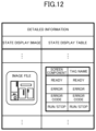
- the controller 14 stores, as detailed information and in the template, the state display image and the state display table corresponding to each unit, together with the path in association with the configuration property and the model name property.
- FIG. 12 illustrates a concrete example of the detailed information. As illustrated in FIG. 12 , the detailed information includes (i) an image file illustrating the state display image and (ii) a state display table read from the image storage 12 .
- the state display table is table data that associates an object name of a screen component that displays the operating state with the tag name for acquiring the operating state from the server 20 .
- the object name of the screen component is previously set.
- a value equal to the tag name in the hierarchization information 233 is assigned to the tag name by the controller 14 .
- the controller 14 prepares the template in the above-described manner.
- the controller 14 generates screen data from the prepared template and transmits the generated screen data to the display 15 , thereby causing display of the monitoring screen 101 on the display 15 .
- the controller 14 updates the display content of the monitoring screen 101 by using the data that indicates the operating state and that is acquired from the server 20 in real time.
- the display 15 is mainly achieved by the outputter 65 of the generation device 10 . Specifically, the display 15 displays, on the screen and in accordance with the instruction of the controller 14 , the information provided by the controller 14 .
- FIG. 13 illustrates server processing executed by the server 20 . This server processing is started by executing a specific program of the server 20 .
- the server 20 selects one unselected control device from connected control devices 30 (step S 11 ). Specifically, the controller 24 selects, in predetermined order, one control device 30 from one or more control devices 30 capable of communicating with the server 20 .
- the predetermined order may be, for example, order of establishment of communication or ascending order regarding values of communication addresses.
- the server 20 acquires the device identification information and the unit configuration information from the selected control device 30 (step S 12 ). Specifically, the controller 24 acquires the notification information by requesting the control device 30 to send notification of the device identification information and the unit configuration information via the second communicator 22 . Next, the controller 24 stores the acquired information in the configuration information storage area 231 of the server storage 23 .
- the server 20 reads, from the server storage 23 , the setting information corresponding to the unit configuration information (step S 13 ).
- the controller 24 finds and reads, from the setting information storage area 232 of the server storage 23 , the setting information corresponding to the same values as the type and the model name of the unit configuration information acquired in step S 12 .
- the setting information relating to each of the units included in the control device 30 selected in step S 11 is read.
- the server 20 generates the hierarchization information 233 in which the device identification information, the unit configuration information, and the setting information are hierarchized in that order (step S 14 ).
- the controller 24 associates the device identification information and the unit configuration information that are acquired in step S 12 with the setting information read in step S 13 , thereby generating the hierarchization information 233 as a block of structured data.
- the controller 24 stores the generated hierarchization information 233 in the server storage 23 .
- the server 20 determines whether the hierarchization information 233 is generated for all the control devices 30 (step S 15 ). Specifically, the controller 24 determines whether the hierarchization information 233 for all the control devices 30 connected and communication-capable with the server 20 is stored in the server storage 23 .
- the server 20 determines that the hierarchization information 233 is not generated for all the control devices 30 (No in step S 15 )
- the server 20 repeats the processes of step S 11 and beyond.
- the hierarchization information 233 is generated, in order, for unselected control devices 30 and is stored in the server storage 23 .
- the server 20 determines that the hierarchization information 233 is generated for all the control devices 30 (Yes in step S 15 )
- the server 20 provides the hierarchization information 233 in response to the external request (step S 16 ).
- the controller 24 reads the hierarchization information 233 from the server storage 23 in response to a request from the generation device 10 and provides the read information. Afterward, the server processing ends.
- Template preparation processing executed by the generation device 10 is described next with reference to FIG. 14 .
- This template preparation processing is started by executing a specific program of the generation device 10 .
- the generation device 10 acquires the hierarchization information 233 for all of control devices 30 serving as subject of monitored (step S 21 ). Specifically, the controller 14 acquires the hierarchization information 233 by requesting the server 20 to provide the hierarchization information 233 relating to one or more control devices 30 .
- the control devices 30 to be monitored may be all of control devices 30 connected to the server 20 , control devices 30 selected by the user or control devices 30 satisfying a condition previously preset in the generation device 10 .
- the preset condition may be, for example, a condition that the user can perform monitoring by access authority previously given to the user.
- the generation device 10 prepares, for each control device 30 , a template that includes (i) a type indicated by the unit configuration information as the unit configuration property and (ii) a model indicated by the unit configuration information as the model name property (step S 22 ). Specifically, the controller 14 generates data of a template including a value equal to the unit configuration information in the hierarchization information 233 acquired in step S 21 .
- the generation device 10 stores, as a unit file property and in the template, the location information of the unit image corresponding to the unit configuration information (step S 23 ).
- the controller 14 (i) searches the image storage 12 for a unit image corresponding to the unit configuration information in the hierarchization information 233 acquired in step S 21 and (ii) stores, in the template prepared in step S 22 , a path of this unit image in the image storage unit 12 .
- the generation device 10 (i) generates the state display table including, as a tag name, a label of an operating state indicated by the setting information and (ii) stores the generated table in the template (step S 24 ).
- the controller 14 (i) generates the state display table including a value equal to the tag name included in the setting information in the hierarchization information 233 acquired in step S 21 and (ii) stores the generated state display table in the detailed information of the template prepared in step S 22 .
- templates for generating screen data used for displaying the monitoring screen 101 on the display 15 are completed for all the control devices 30 .
- Monitoring processing executed by the generation device 10 is next described with reference to FIG. 15 .
- the monitoring processing starts by executing a specific program of the generation device 10 after the completion of the template preparation processing.
- the generation device 10 determines whether the monitoring screen 101 is changed (step S 31 ). Specifically, the controller 14 determines whether the user previously inputs a change instruction to change the monitoring screen 101 .
- the processing by the generation device 10 proceeds to step S 33 .
- the generation device 10 changes the monitoring screen 101 in accordance with the change instruction.
- the controller 14 changes the template in accordance with the change instruction (step S 32 ).
- the change instruction may include, for example, (i) a change of arrangement of screen components and (ii) addition and deletion of a screen component.
- the generation device 10 (i) acquires, from the server 20 and by the tag name, an operating state of the control device 30 serving as the subject of monitoring and (ii) generates the screen data based on the template (step S 33 ). Specifically, the controller 14 queries the server 20 as to the operating state identified by the tag name. Since the server 20 acquires the operating state of each of the control devices 30 in real time, the generation device 10 can acquire the operating states of the control devices 30 from the server 20 .
- the generation device 10 transmits the screen data to the display 15 , thereby updating and displaying the monitoring screen 101 (step S 34 ). Afterward, the processing by the generation device 10 repeats the processes after step S 33 . As a result, the display content of the monitoring screen 101 is updated.
- the relevance of the screen components of the monitoring screen 101 to the data of each unit becomes clear via the state display table of the template and the information managed by the server 20 . Additionally, such relevance is defined using the hierarchization information 233 as illustrated in FIG. 8 .
- the server 20 acquires, from the control devices 30 , the device identification information and the unit configuration information, and the generation device 10 thus generates, from the template including the unit configuration information, the screen data relating to the control devices 30 indicated by the device identification information. Accordingly, the work of creating the monitoring screen 101 can be drastically simplified. As a result, the workload of preparing the monitoring screen 101 can be reduced. Specifically, engineering man-hours for creating the monitoring screen 101 can be reduced, and the engineering cost at the time of system integration can be reduced.
- the monitoring screen 101 is also to be changed.
- the monitoring screen 101 is changed in accordance with the configuration of the control system 1000 . Accordingly, work of redesigning the monitoring screen 101 becomes unnecessary. As a result, expansion of the control system 1000 becomes easy.
- the data relating to the control devices 30 is provided as the structured hierarchization information 233 . Accordingly, data management between the generation device 10 and the server 20 becomes easy. Also, even when the monitoring screen 101 is changed, there is no need for an operator himself/herself to pay attention to the relationship between (i) the screen components for monitoring states of the units and (ii) the configurations of the control devices 30 , and the operator can easily perform the work.
- the device address is managed, by the server 20 , together with the tag name
- the tag name is managed, by the generation device 10 , together with the names of the screen components. Accordingly, there is no need for the operator to grasp the device address and the tag name, and the operator has only to simply give an instruction to change a screen component as an object to be changed.
- the generation device 10 generates the screen data by combining the setting information with the template including the unit configuration information in the hierarchization information 233 . Specifically, as illustrated in FIG. 10 , after adding, to the template including the type and model name of the unit on the basis of the setting information, a state display table including the tag name illustrated in FIG. 12 , the generation device 10 generates the screen data from this template. As a result, the generation device 10 is capable of display of various types of information on the monitoring screen 101 by using the setting information previously stored in the server 20 together with the information transmitted from the control devices 30 .
- the setting information includes (i) the label of the operating state of the unit and (ii) the address of the unit indicating the area in which the data indicating the operating state is stored.
- the generation device 10 applies, to the tag name in the state display table, the label in the setting information. As a result, the generation device 10 can acquire the operating state of the unit by using the label without managing the device address.
- the server 20 previously stores multiple pieces of the setting information, selects the setting information corresponding to the unit configuration information transmitted from the control devices 30 , and generates the hierarchization information 233 . Accordingly, the server 20 can generate the hierarchization information 233 from the setting information corresponding to various units that each of the control devices 30 can include.
- the generation device 10 (i) stores the unit image that is an image representing the appearance of each unit and (ii) generates the screen data from the template including the path of the unit image. Accordingly, the appearance of the unit is displayed on the monitoring screen 101 based on the screen data.
- the user who visually confirms the monitoring screen 101 can visually confirm, on the monitoring screen 101 , an image having the same configuration as the actual external appearance of each of the control devices 30 .
- a control device 30 whose state is displayed on the monitoring screen 101 can be easily associated with a housing of an actual control device 30 .
- the generation device 10 and the server 20 are devices separate from each other is described above, without particular limitation.
- the generation device 10 may have the function of the server 20 achieved by software.
- the generation device 10 itself displays the monitoring screen 101 is described above, without particular limitation. As illustrated in FIG. 18 , the generation device 10 may display the monitoring screen 101 by transmitting screen data to an external display terminal 15 a.
- the image storage 12 may be omitted in configuration of the generation device 10
- the setting information storage area 232 of the server storage 23 may be omitted in configuration of the server 20 .
- the generation device 10 may acquire necessary information from an external image server 12 a that stores data similar to that stored in the image storage 12
- the server 20 may acquire necessary information from an external setting information server 232 a that stores the information similar to that stored in the setting information storage area 232 .
- the generation device 10 may (i) select a template corresponding to the unit configuration information included in the hierarchization information 233 acquired from the server 20 and (ii) apply the setting information to the selected template, thereby changing to a state in which the template can be used in the monitoring processing.
- the device address included in the setting information may be omitted.
- the setting information may include other information different from the label and the device address of the operating state.
- the functions of the generation device 10 and the server 20 can be achieved by dedicated hardware or by a normal computer system.
- the program P 1 executed by the processor 61 is stored in a non-transitory computer readable recording medium, the recording medium storing the program P 1 is distributed, and then the program P 1 is installed in a computer, thereby enabling production of a device for executing the above-described processing.
- a recording medium include a compact disc-read only memory (CD-ROM), a digital versatile disc (DVD), and a magneto-optical disk (MO).
- the program P 1 may be previously stored in a disk device that is included in a server device on a communication network typified by the Internet, and the program P 1 may be downloaded onto the computer, for example, by superimposing the program P 1 on a carrier wave.
- the above-described processing can be achieved by launching and executing the program P 1 while transferring the program P 1 via the communication network.
- processing can be also achieved by (i) executing the whole of or a part of the program P 1 on the server device and (ii) executing the program while the computer is transmitting and receiving information relating to the processing via the communication network.
- OS operating systems
- storage of only a portion other than the OS in the recording medium is permissible, and such a recording medium may be distributed or the portion other than the OSs may be downloaded onto the computer.
- means for achieving the functions of the generation device 10 and the server 20 is not limited to software, and a part or the whole of the functions may be achieved by dedicated hardware including a circuit.
- the present disclosure is suitable for monitoring an operating state of a system.
Abstract
Description
-
- 1000 Control system
- 100 Screen data generating system
- 101 Monitoring screen
- 10 Generation device
- 11 Communicator
- 12 Image storage
- 12 a Image server
- 13 Template storage
- 14 Controller
- 15 Display
- 15 a Display terminal
- 20 Server
- 21 First communicator
- 22 Second communicator
- 23 Server storage
- 231 Configuration information storage area
- 232 Setting information storage area
- 232 a Setting information server
- 233 Hierarchization information
- 24 Controller
- 30 Control device
- 40 Apparatus
- 50-55 Image
- 56 Pane
- 61 Processor
- 62 Main storage
- 63 Auxiliary storage
- 64 Inputter
- 65 Outputter
- 66 Communicator
- 67 Internal bus
- 561 Box
- 562, 563 Area
- P1 Program
Claims (11)
Applications Claiming Priority (1)
| Application Number | Priority Date | Filing Date | Title |
|---|---|---|---|
| PCT/JP2019/017814 WO2020217435A1 (en) | 2019-04-25 | 2019-04-25 | Screen data generating system, screen data generating method, and program |
Publications (2)
| Publication Number | Publication Date |
|---|---|
| US20220147296A1 US20220147296A1 (en) | 2022-05-12 |
| US11842116B2 true US11842116B2 (en) | 2023-12-12 |
Family
ID=72940889
Family Applications (1)
| Application Number | Title | Priority Date | Filing Date |
|---|---|---|---|
| US17/435,392 Active 2039-07-28 US11842116B2 (en) | 2019-04-25 | 2019-04-25 | Screen data generating system, screen data generating method, and program |
Country Status (5)
| Country | Link |
|---|---|
| US (1) | US11842116B2 (en) |
| JP (1) | JP6790308B1 (en) |
| CN (1) | CN113728286A (en) |
| DE (1) | DE112019007250T5 (en) |
| WO (1) | WO2020217435A1 (en) |
Citations (11)
| Publication number | Priority date | Publication date | Assignee | Title |
|---|---|---|---|---|
| JP2002333917A (en) | 2001-05-09 | 2002-11-22 | Hitachi Ltd | State display method for controller |
| JP2004030345A (en) | 2002-06-26 | 2004-01-29 | Omron Corp | Picture generating device and program product |
| EP1420308A2 (en) * | 2002-11-14 | 2004-05-19 | Rockwell Automation Technologies, Inc. | Industrial control and monitoring method and system |
| JP2007179115A (en) | 2005-12-26 | 2007-07-12 | Digital Electronics Corp | Programmable display, control program, recording medium with the program recorded thereon, server, server program, and recording medium with the program recorded thereon |
| JP2010160582A (en) | 2009-01-06 | 2010-07-22 | Mitsubishi Electric Corp | Plc system construction support device |
| JP2010272034A (en) | 2009-05-25 | 2010-12-02 | Mitsubishi Electric Corp | System configuration design device, system configuration design program and recording medium |
| JP2012141722A (en) | 2010-12-28 | 2012-07-26 | Mitsubishi Electric Corp | Setting device |
| US20120290107A1 (en) * | 2011-05-12 | 2012-11-15 | John Carlson | Apparatus and method for displaying state data of an industrial plant |
| WO2013150618A1 (en) | 2012-04-04 | 2013-10-10 | 三菱電機株式会社 | Plc designing device |
| WO2014064819A1 (en) | 2012-10-25 | 2014-05-01 | 三菱電機株式会社 | System building assistance tool and system |
| WO2016155856A1 (en) | 2015-03-27 | 2016-10-06 | Bühler AG | Method and system for process controlling of plants in an opc-ua based machine-to-machine network |
Family Cites Families (6)
| Publication number | Priority date | Publication date | Assignee | Title |
|---|---|---|---|---|
| JP4758950B2 (en) * | 2007-06-07 | 2011-08-31 | 株式会社日立製作所 | PLANT MONITORING DEVICE AND PLANT OPERATION MONITORING METHOD |
| JP5683998B2 (en) * | 2011-02-28 | 2015-03-11 | オリンパス株式会社 | Server system and client device control method |
| JP6129690B2 (en) * | 2013-08-30 | 2017-05-17 | 株式会社東芝 | Image generation apparatus, image generation system, and image generation method |
| KR101860252B1 (en) * | 2014-02-12 | 2018-05-21 | 미쓰비시덴키 가부시키가이샤 | Plotting device and control system |
| WO2015170408A1 (en) * | 2014-05-09 | 2015-11-12 | 三菱電機株式会社 | Monitoring control system, monitoring terminal, and monitoring program |
| WO2017072928A1 (en) * | 2015-10-29 | 2017-05-04 | 三菱電機株式会社 | Programmable display device, information processing device, screen data creation assistance program, and screen display system |
-
2019
- 2019-04-25 US US17/435,392 patent/US11842116B2/en active Active
- 2019-04-25 DE DE112019007250.1T patent/DE112019007250T5/en active Pending
- 2019-04-25 JP JP2020528369A patent/JP6790308B1/en active Active
- 2019-04-25 CN CN201980095625.1A patent/CN113728286A/en active Pending
- 2019-04-25 WO PCT/JP2019/017814 patent/WO2020217435A1/en active Application Filing
Patent Citations (15)
| Publication number | Priority date | Publication date | Assignee | Title |
|---|---|---|---|---|
| JP2002333917A (en) | 2001-05-09 | 2002-11-22 | Hitachi Ltd | State display method for controller |
| JP2004030345A (en) | 2002-06-26 | 2004-01-29 | Omron Corp | Picture generating device and program product |
| EP1420308A2 (en) * | 2002-11-14 | 2004-05-19 | Rockwell Automation Technologies, Inc. | Industrial control and monitoring method and system |
| JP2007179115A (en) | 2005-12-26 | 2007-07-12 | Digital Electronics Corp | Programmable display, control program, recording medium with the program recorded thereon, server, server program, and recording medium with the program recorded thereon |
| JP2010160582A (en) | 2009-01-06 | 2010-07-22 | Mitsubishi Electric Corp | Plc system construction support device |
| JP2010272034A (en) | 2009-05-25 | 2010-12-02 | Mitsubishi Electric Corp | System configuration design device, system configuration design program and recording medium |
| JP2012141722A (en) | 2010-12-28 | 2012-07-26 | Mitsubishi Electric Corp | Setting device |
| US20120290107A1 (en) * | 2011-05-12 | 2012-11-15 | John Carlson | Apparatus and method for displaying state data of an industrial plant |
| WO2013150618A1 (en) | 2012-04-04 | 2013-10-10 | 三菱電機株式会社 | Plc designing device |
| US20150032419A1 (en) | 2012-04-04 | 2015-01-29 | Mitsubishi Electric Corporation | Plc designing apparatus |
| WO2014064819A1 (en) | 2012-10-25 | 2014-05-01 | 三菱電機株式会社 | System building assistance tool and system |
| US20150220076A1 (en) | 2012-10-25 | 2015-08-06 | Mitsubishi Electric Corporation | System construction support tool and system |
| WO2016155856A1 (en) | 2015-03-27 | 2016-10-06 | Bühler AG | Method and system for process controlling of plants in an opc-ua based machine-to-machine network |
| US20180088541A1 (en) | 2015-03-27 | 2018-03-29 | Bühler AG | Adaptive cross plant control and steering system, and corresponding method thereof |
| JP2018515865A (en) | 2015-03-27 | 2018-06-14 | ビューラー アーゲー | Method and system for process control of a plant in an OPC UA based machine-to-machine network |
Non-Patent Citations (5)
| Title |
|---|
| "Control system, program thereof and recording medium", published on Apr. 11, 2007, Document ID: JP-3904865-B2, pp. 17 (Year: 2007). * |
| International Search Report and Written Opinion dated Jul. 30, 2019, received for PCT Application PCT/JP2019/017814, Filed on Apr. 25, 2019, 9 pages including English Translation. |
| Notice of Reasons for Refusal dated Aug. 11, 2020, received for JP Application 2020-528369, 4 pages including English Translation. |
| Office Action dated Dec. 23, 2022, in corresponding Indian patent Application No. 202127041999, 7 pages. |
| Ryo Uchida, "System Building Assistance Tool and System", published on May 1, 2014, Document ID: WO-2014064819-A1, pp. 16 (Year: 2014). * |
Also Published As
| Publication number | Publication date |
|---|---|
| US20220147296A1 (en) | 2022-05-12 |
| JPWO2020217435A1 (en) | 2021-05-06 |
| WO2020217435A1 (en) | 2020-10-29 |
| DE112019007250T5 (en) | 2022-01-13 |
| CN113728286A (en) | 2021-11-30 |
| JP6790308B1 (en) | 2020-11-25 |
Similar Documents
| Publication | Publication Date | Title |
|---|---|---|
| US9372479B1 (en) | System and method for a database layer for managing a set of energy consuming devices | |
| CN108009081B (en) | Engineering design tool cooperation device and engineering design tool cooperation method | |
| US10162328B2 (en) | Controller and control system | |
| US11334550B2 (en) | Controller, control method, and control program for SQL statement generation in a factory automation database | |
| US11281650B2 (en) | Control system, controller, and control method | |
| CN102414657B (en) | System and method for sharing job scheduling in electronic notebook | |
| EP3761127A1 (en) | Display device, screen generation method, and screen generation program | |
| US11842116B2 (en) | Screen data generating system, screen data generating method, and program | |
| JP2019046052A (en) | Control system, development support device, and control method | |
| JP2010287034A (en) | Address display system of modbus protocol communication between external equipment and plc | |
| US10108187B2 (en) | Control device, control system, support device, and control-device maintenance management method | |
| JP2005259079A (en) | Tool | |
| EP3767411A1 (en) | Control system, development assistance device, and development assistance program | |
| JP2020016998A (en) | Management device of industrial machinery | |
| KR20160049568A (en) | System and method for comparing and managing source code | |
| JP6793881B1 (en) | Management equipment, management system, management method and program | |
| US20210018907A1 (en) | Management device, management system, display method, and program | |
| JP2021068365A (en) | Computer system and method for controlling data | |
| JP2009282934A (en) | Programmable controller system | |
| JP6776191B2 (en) | Gateway devices, data access methods performed by gateway devices, controllers, and data access methods performed by controllers. | |
| JP2003295910A (en) | Unit, tool equipment, and program product | |
| JP6741850B1 (en) | Machine system, machine tool, information processing system, setting data inheritance method, and setting data inheritance program | |
| JPH1063312A (en) | Program managing device for controlling plant | |
| US11507567B2 (en) | Framework for managing tag bundles | |
| US20220398355A1 (en) | Design support device and storage medium |
Legal Events
| Date | Code | Title | Description |
|---|---|---|---|
| AS | Assignment |
Owner name: MITSUBISHI ELECTRIC CORPORATION, JAPAN Free format text: ASSIGNMENT OF ASSIGNORS INTEREST;ASSIGNORS:SHIMIZU, YUKI;GOTO, YASUAKI;SIGNING DATES FROM 20210713 TO 20210720;REEL/FRAME:057404/0372 |
|
| FEPP | Fee payment procedure |
Free format text: ENTITY STATUS SET TO UNDISCOUNTED (ORIGINAL EVENT CODE: BIG.); ENTITY STATUS OF PATENT OWNER: LARGE ENTITY |
|
| STPP | Information on status: patent application and granting procedure in general |
Free format text: DOCKETED NEW CASE - READY FOR EXAMINATION |
|
| STPP | Information on status: patent application and granting procedure in general |
Free format text: NON FINAL ACTION MAILED |
|
| STPP | Information on status: patent application and granting procedure in general |
Free format text: RESPONSE TO NON-FINAL OFFICE ACTION ENTERED AND FORWARDED TO EXAMINER |
|
| STPP | Information on status: patent application and granting procedure in general |
Free format text: NOTICE OF ALLOWANCE MAILED -- APPLICATION RECEIVED IN OFFICE OF PUBLICATIONS |
|
| STPP | Information on status: patent application and granting procedure in general |
Free format text: PUBLICATIONS -- ISSUE FEE PAYMENT RECEIVED |
|
| STPP | Information on status: patent application and granting procedure in general |
Free format text: PUBLICATIONS -- ISSUE FEE PAYMENT VERIFIED |
|
| STPP | Information on status: patent application and granting procedure in general |
Free format text: PUBLICATIONS -- ISSUE FEE PAYMENT VERIFIED |
|
| STCF | Information on status: patent grant |
Free format text: PATENTED CASE |