US11833635B2 - Polishing system, learning device, and learning method of learning device - Google Patents
Polishing system, learning device, and learning method of learning device Download PDFInfo
- Publication number
- US11833635B2 US11833635B2 US16/774,010 US202016774010A US11833635B2 US 11833635 B2 US11833635 B2 US 11833635B2 US 202016774010 A US202016774010 A US 202016774010A US 11833635 B2 US11833635 B2 US 11833635B2
- Authority
- US
- United States
- Prior art keywords
- polishing
- learning
- condition
- workpiece
- corrected
- Prior art date
- Legal status (The legal status is an assumption and is not a legal conclusion. Google has not performed a legal analysis and makes no representation as to the accuracy of the status listed.)
- Active, expires
Links
- 238000005498 polishing Methods 0.000 title claims abstract description 550
- 238000000034 method Methods 0.000 title claims description 118
- 230000006870 function Effects 0.000 claims abstract description 40
- 238000004364 calculation method Methods 0.000 claims abstract description 13
- 239000002002 slurry Substances 0.000 claims description 28
- 238000012545 processing Methods 0.000 description 59
- 238000007517 polishing process Methods 0.000 description 19
- 238000009826 distribution Methods 0.000 description 18
- 238000003860 storage Methods 0.000 description 17
- 238000012937 correction Methods 0.000 description 16
- 238000001514 detection method Methods 0.000 description 15
- 230000007423 decrease Effects 0.000 description 13
- 238000005259 measurement Methods 0.000 description 8
- 238000005070 sampling Methods 0.000 description 6
- 238000005516 engineering process Methods 0.000 description 5
- 238000011156 evaluation Methods 0.000 description 5
- 230000005856 abnormality Effects 0.000 description 4
- 238000010586 diagram Methods 0.000 description 4
- 238000004904 shortening Methods 0.000 description 4
- 239000000126 substance Substances 0.000 description 4
- 230000003247 decreasing effect Effects 0.000 description 3
- 230000002787 reinforcement Effects 0.000 description 3
- 238000007730 finishing process Methods 0.000 description 2
- 239000006061 abrasive grain Substances 0.000 description 1
- 238000013528 artificial neural network Methods 0.000 description 1
- 238000006243 chemical reaction Methods 0.000 description 1
- 238000011109 contamination Methods 0.000 description 1
- 238000001816 cooling Methods 0.000 description 1
- 230000000694 effects Effects 0.000 description 1
- 238000012905 input function Methods 0.000 description 1
- 238000005457 optimization Methods 0.000 description 1
- 238000003825 pressing Methods 0.000 description 1
- 239000004065 semiconductor Substances 0.000 description 1
- 230000003746 surface roughness Effects 0.000 description 1
Images


Classifications
-
- B—PERFORMING OPERATIONS; TRANSPORTING
- B24—GRINDING; POLISHING
- B24B—MACHINES, DEVICES, OR PROCESSES FOR GRINDING OR POLISHING; DRESSING OR CONDITIONING OF ABRADING SURFACES; FEEDING OF GRINDING, POLISHING, OR LAPPING AGENTS
- B24B37/00—Lapping machines or devices; Accessories
- B24B37/005—Control means for lapping machines or devices
-
- B—PERFORMING OPERATIONS; TRANSPORTING
- B24—GRINDING; POLISHING
- B24B—MACHINES, DEVICES, OR PROCESSES FOR GRINDING OR POLISHING; DRESSING OR CONDITIONING OF ABRADING SURFACES; FEEDING OF GRINDING, POLISHING, OR LAPPING AGENTS
- B24B37/00—Lapping machines or devices; Accessories
- B24B37/04—Lapping machines or devices; Accessories designed for working plane surfaces
- B24B37/042—Lapping machines or devices; Accessories designed for working plane surfaces operating processes therefor
-
- B—PERFORMING OPERATIONS; TRANSPORTING
- B24—GRINDING; POLISHING
- B24B—MACHINES, DEVICES, OR PROCESSES FOR GRINDING OR POLISHING; DRESSING OR CONDITIONING OF ABRADING SURFACES; FEEDING OF GRINDING, POLISHING, OR LAPPING AGENTS
- B24B37/00—Lapping machines or devices; Accessories
- B24B37/04—Lapping machines or devices; Accessories designed for working plane surfaces
- B24B37/07—Lapping machines or devices; Accessories designed for working plane surfaces characterised by the movement of the work or lapping tool
- B24B37/10—Lapping machines or devices; Accessories designed for working plane surfaces characterised by the movement of the work or lapping tool for single side lapping
- B24B37/105—Lapping machines or devices; Accessories designed for working plane surfaces characterised by the movement of the work or lapping tool for single side lapping the workpieces or work carriers being actively moved by a drive, e.g. in a combined rotary and translatory movement
-
- B—PERFORMING OPERATIONS; TRANSPORTING
- B24—GRINDING; POLISHING
- B24B—MACHINES, DEVICES, OR PROCESSES FOR GRINDING OR POLISHING; DRESSING OR CONDITIONING OF ABRADING SURFACES; FEEDING OF GRINDING, POLISHING, OR LAPPING AGENTS
- B24B49/00—Measuring or gauging equipment for controlling the feed movement of the grinding tool or work; Arrangements of indicating or measuring equipment, e.g. for indicating the start of the grinding operation
- B24B49/10—Measuring or gauging equipment for controlling the feed movement of the grinding tool or work; Arrangements of indicating or measuring equipment, e.g. for indicating the start of the grinding operation involving electrical means
-
- B—PERFORMING OPERATIONS; TRANSPORTING
- B24—GRINDING; POLISHING
- B24B—MACHINES, DEVICES, OR PROCESSES FOR GRINDING OR POLISHING; DRESSING OR CONDITIONING OF ABRADING SURFACES; FEEDING OF GRINDING, POLISHING, OR LAPPING AGENTS
- B24B49/00—Measuring or gauging equipment for controlling the feed movement of the grinding tool or work; Arrangements of indicating or measuring equipment, e.g. for indicating the start of the grinding operation
- B24B49/14—Measuring or gauging equipment for controlling the feed movement of the grinding tool or work; Arrangements of indicating or measuring equipment, e.g. for indicating the start of the grinding operation taking regard of the temperature during grinding
-
- B—PERFORMING OPERATIONS; TRANSPORTING
- B24—GRINDING; POLISHING
- B24B—MACHINES, DEVICES, OR PROCESSES FOR GRINDING OR POLISHING; DRESSING OR CONDITIONING OF ABRADING SURFACES; FEEDING OF GRINDING, POLISHING, OR LAPPING AGENTS
- B24B49/00—Measuring or gauging equipment for controlling the feed movement of the grinding tool or work; Arrangements of indicating or measuring equipment, e.g. for indicating the start of the grinding operation
- B24B49/16—Measuring or gauging equipment for controlling the feed movement of the grinding tool or work; Arrangements of indicating or measuring equipment, e.g. for indicating the start of the grinding operation taking regard of the load
Definitions
- the present disclosure relates to a polishing system, a learning device, and a learning method of the learning device.
- CMP Chemical Mechanical Polishing
- a mechanical polishing technology in which the polishing is executed on a workpiece by supplying slurry onto a polishing pad and interposing the slurry between the workpiece and the polishing pad, while rotating and pressing the workpiece with a polishing head, for the polishing pad generally affixed on a surface plate, and which is mainly used for a polishing process of semiconductor board components.
- This polishing process is a process in which the workpiece is easily processed by a chemical action of the slurry and the workpiece is polished by the action of the abrasive grains. Even now, generally, it is an unstable process that generally polishes the workpiece based on an estimated polishing rate based on empirical rules such as Preston's law (or Preston equation).
- a technology in which a dressing condition for a polishing pad, surface property measurement data of a polishing pad, and polishing result data are input to a neural network, and a correlation of each data is calculated and learned according to a predetermined program.
- estimated dressing condition data at the time of dressing the surface of the polishing pad is calculated, and an operator executes dressing on the polishing pad by driving a dressing unit based on the estimated dressing condition data.
- a polishing system of the disclosure includes a polishing device that applies a load by a polishing head to a workpiece on a polishing pad of a surface plate, supplies slurry onto the polishing pad, and executes polishing on the workpiece by rotating each of the surface plate and the polishing head, and a learning device that corrects the polishing executed by the polishing device through learning, in which in the learning device, a state information receiving unit that receives state information including (i) at least one polishing condition relating to the polishing, and (ii) a calculation result calculated based on at least one measured value measured during execution of the polishing, a learning unit that updates, based on the state information during the polishing, an action value function in which the state information and a corrected polishing condition for correcting the polishing condition are associated with each other, and a determination unit that determines the corrected polishing condition corresponding to the state information during the polishing, based on the action value function updated by the learning unit, are included.
- a learning device of the disclosure that corrects, through learning, polishing on a workpiece executed by a polishing device by applying a load by a polishing head to the workpiece on a polishing pad of a surface plate, supplying slurry onto the polishing pad, and rotating each of the surface plate and the polishing head includes a state information receiving unit that receives state information including (i) at least one polishing condition relating to the polishing, and (ii) a calculation result calculated based on at least one measured value measured during execution of the polishing, a learning unit that updates an action value function in which the state information and a corrected polishing condition for correcting the polishing condition are associated with each other, based on the state information during the polishing, and a determination unit that determines the corrected polishing condition corresponding to the state information during the polishing, based on the action value function updated by the learning unit.
- a learning method of a learning device of the disclosure that corrects, through learning, polishing on a workpiece executed by a polishing device by applying a load by a polishing head to the workpiece on a polishing pad of a surface plate, supplying slurry onto the polishing pad, and rotating each of the surface plate and the polishing head includes receiving state information including (i) at least one polishing condition relating to the polishing, and (ii) a calculation result calculated based on at least one measured value measured during execution of the polishing, updating an action value function in which the state information and a corrected polishing condition for correcting the polishing condition are associated with each other, based on the state information during the polishing, and determining the corrected polishing condition corresponding to the state information during the polishing, based on the updated action value function.
- FIG. 1 is a diagram showing a configuration of a polishing system according to an embodiment of the disclosure
- FIG. 2 A is a graph showing relationship between rotational torque of a polishing head and a polishing time during polishing according to the embodiment of the disclosure
- FIG. 2 B is another graph showing a relationship between the rotational torque of a polishing head and the polishing time during the polishing according to the embodiment of the disclosure
- FIG. 3 A is a graph showing a relationship between a horizontal load and the polishing time on the polishing head during the polishing according to the embodiment of the disclosure
- FIG. 3 B is another graph showing a relationship between a horizontal load and the polishing time on the polishing head during the polishing according to the embodiment of the disclosure
- FIG. 4 is a graph showing a relationship between temperature difference in an inner circumference side and an outer circumference side of the polishing head and the polishing time during the polishing according to the embodiment of the disclosure;
- FIG. 5 is a graph showing a relationship of difference in the friction distance between the outer circumference side and a center side of a workpiece, and the difference in the number of rotation between a surface plate and the polishing head according to the embodiment of the disclosure;
- FIG. 6 is a diagram showing the outline of a learning process according to the embodiment of the disclosure.
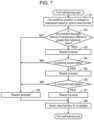
- FIG. 7 is a flowchart showing a first half learning process according to the embodiment of the disclosure.
- FIG. 8 is a flowchart showing a second half learning process according to the embodiment of the disclosure.
- FIG. 9 is a flowchart showing a process executed by a polishing device and a learning device including a polishing system according to the embodiment.
- FIG. 10 is a graph showing the actual measured value of the number of rotation of the surface plate or the number of rotation of the polishing head, when the polishing device is operated normally.
- FIG. 11 is a graph showing the actual measured value of the number of rotation of the surface plate or the number of rotation of the polishing head, when an abnormality occurs in the polishing device.
- An object of the disclosure is to stabilize the polishing process by evaluating the state of the polishing process based on the real-time data generated during the polishing on the workpiece.
- FIG. 1 is a diagram showing a configuration of a polishing system according to an embodiment of the disclosure.
- Polishing system 1 is configured with polishing device 10 that executes polishing on the workpiece and learning device 20 that executes reinforcement learning by state variables from polishing device 10 .
- Polishing device 10 is configured with polishing processing unit 11 , polishing condition setting unit 12 , measuring unit 13 , state calculating unit 14 , and state variable storage unit 15 .
- Polishing processing unit 11 is for executing chemical mechanical polishing (hereinafter, referred to as polishing) of the surface of the workpiece, and since it is a known technology, detailed description thereof is omitted.
- a torque detection sensor for detecting the rotational torque of a polishing head during the polishing on the surface of the workpiece
- a load detection sensor for detecting load in a horizontal direction applied to the polishing head during the polishing on the surface of the workpiece
- a first temperature detection sensor for detecting temperature of the inner circumference side of the polishing head during the polishing on the surface of the workpiece
- a second temperature detection sensor for detecting temperature of the outer circumference side of the polishing head during the polishing on the surface of the workpiece
- a first rotation number detection sensor for detecting the number of rotation of the surface plate
- a second rotation number detection sensor for detecting the number of rotation of the polishing head, and the like are provided, and detection data detected by each of these sensors is input to measuring unit 13 .
- polishing processing unit 11 to measuring unit 13 various data are transmitted, such as polishing start data indicating the start of polishing, polishing completion data indicating the end of polishing, temperature data of slurry, and part replacement data indicating that various parts such as a polishing pad are replaced, and error data indicating various errors generated in polishing processing unit 11 .
- Polishing condition setting unit 12 is for setting polishing condition data for the workpiece to be polished in polishing processing unit 11 .
- the polishing condition data set in polishing processing unit 11 is output to state variable storage unit 15 .
- polishing condition data set from polishing condition setting unit 12 to polishing processing unit 11 there are the number of rotation of the surface plate, the number of rotation of the polishing head, slurry temperature, the presence or absence of dressing, and the like.
- the polishing condition data of the workpiece is set by being input by an operator, a polishing system central management computer (not shown), or the like.
- Measuring unit 13 is for executing various measurements on polishing processing unit 11 during the polishing.
- Measuring unit 13 receives the detection data from each of the above-described detection sensors and various data. Measuring unit (torque measuring unit) 13 measures the rotational torque of a polishing head from the start of polishing of the surface of the workpiece to the end of polishing every unit time, by receiving torque data detected by the torque detection sensor which is an example of the torque measuring unit. In addition, measuring unit (load measuring unit) 13 measures the load in the horizontal direction applied to the polishing head from the start of polishing of the surface of the workpiece to the end of polishing every unit time, by receiving load data detected by the load detection sensor which is an example of the load measuring unit. Rotational torque data indicating the measured rotational torque and horizontal load data indicating the load in the horizontal direction are transmitted to state calculating unit 14 .
- measuring unit (temperature measuring unit) 13 measures the temperature of the inner circumference side and the temperature of the outer circumference side, every unit time, for an elapsed time from the start of polishing of the surface of the workpiece to the end of polishing, by receiving temperature data of the inner circumference side of the polishing head detected by the first temperature detection sensor which is an example of the temperature measuring unit and the temperature data of the outer circumference side of the polishing head detected by the second temperature detection sensor.
- Inner circumference side temperature data indicating the temperature of the inner circumference side and outer circumference side temperature data indicating the temperature of the outer circumference side which are measured are transmitted to state calculating unit 14 .
- measuring unit (time measuring unit) 13 which is an example of the time measuring unit, resets an accumulated usage time for the polishing pad before exchange by receiving exchange data indicating that the polishing pad is exchanged, and measures (counts) the accumulated usage time by a new polishing pad. Accumulated usage time data indicating the measured accumulated usage time is transmitted to state calculating unit 14 .
- measuring unit 13 measures the number of rotation of the surface plate and the number of rotation of the polishing head every unit time during the polishing, by receiving rotation number data of the surface plate detected by the first rotation number detection sensor and the rotation number data of the polishing head detected by the second rotation number detection sensor.
- the rotation number data of the surface plate indicating the measured rotation number of the surface plate and the rotation number data of the polishing head indicating the number of rotation of the polishing head are transmitted to state calculating unit 14 .
- State calculating unit 14 receives various measurement data from the above-described measuring unit 13 , and calculates to update the amount of various changes within a set time (for example, sample processing time will be described below with reference to FIG. 6 ).
- the calculated amount of change as change amount data is output to state variable storage unit 15 , and stored in state variable storage unit 15 as state variables.
- state calculating unit 14 calculates the amount of change of the rotational torque of the polishing head within the set time.
- the amount of change of the horizontal load of the polishing head is calculated within the set time.
- an absolute value of the temperature difference between the inner circumference side and the outer circumference side of the polishing head is calculated within the set time.
- State calculating unit 14 calculates the amount of change of the temperature difference between the inner circumference side and the outer circumference side of the polishing head within the set time, based on the calculated absolute value of the temperature difference.
- state calculating unit 14 calculates the difference between an actual measured value and a set value of the number of rotation of the surface plate or the polishing head within the set time. State calculating unit 14 outputs each of the calculated amount of change as the change amount data to state variable storage unit 15 . In addition, state calculating unit 14 outputs the calculated absolute value data of the temperature difference, difference data of the number of rotation of the surface plate, and the difference data of the number of rotation of the polishing head to state variable storage unit 15 . Furthermore, state calculating unit 14 outputs the accumulated usage time data measured by measuring unit 13 to state variable storage unit 15 .
- State variable storage unit 15 stores the change amount data of the rotational torque of the polishing head, the change amount data of the horizontal load of the polishing head, the absolute value data and the change amount data of the temperature difference between the inner circumference side and the outer circumference side of the polishing head, the difference data of the number of rotation of the surface plate and the polishing head, the accumulated usage time data, and the like output from the above-described state calculating unit 14 , and the polishing condition data (the number of rotation of surface plate, the number of rotation of the polishing head, polishing load, slurry temperature, slurry pH, slurry flow rate, processing time, type of polishing pad, presence or absence of dressing, and the like) output from the above-described polishing condition setting unit 12 as state variables (state data).
- state variable storage unit 15 transmits the received state variable to a learning device 20 .
- the transmitted state variable is received by state variable receiving unit 21 of learning device 20 .
- Each configuration included in polishing device 10 may be present independently. In this case, it is preferable that components are connected wirelessly or by a wire to exchange data and the like.
- polishing processing unit 11 is a device for executing general chemical mechanical polishing
- polishing condition setting unit 12 is a device having an input function such as a touch panel and a keyboard
- state calculating unit 14 and state variable storage unit 15 are computers having a CPU.
- Learning device 20 corrects the polishing executed by polishing device 10 by learning.
- Learning device 20 is configured with state variable receiving unit 21 and learning unit 22 .
- State variable receiving unit (state information receiving unit) 21 receives the state variable transmitted from the above-described state variable storage unit 15 and transmits the received result to learning unit 22 . That is, state variable receiving unit 21 receives state information including at least one polishing condition relating to polishing and a calculation result calculated based on at least one measured value measured during the execution of the polishing.
- Learning unit 22 is configured with state variable history storage unit 23 , learning processing unit 24 , and correction polishing condition determination unit 25 .
- State variable history storage unit 23 stores the state variable transmitted from the above-described state variable receiving unit 21 as the history data of the state variable.
- Each of the state variables (change amount data of rotational torque of polishing head, change amount data of horizontal load of polishing head, change amount data of temperature difference between inner circumference side and outer circumference side of polishing head, the number of rotation of surface plate, the number of rotation of polishing head, slurry temperature, presence or absence of dressing, and the like) is stored in association with the reception date and time.
- the state variables include at least one polishing condition (the number of rotation of surface plate, the number of rotation of polishing head, slurry temperature, presence or absence of dressing, and the like) relating to the polishing, and a calculation result (change amount data of rotational torque of polishing head, change amount data of horizontal load of polishing head, absolute value data and change amount data of temperature difference between inner circumference side and outer circumference side of polishing head, difference data of the number of rotation of surface plate and polishing head, accumulated usage time data, and the like) calculated based on at least one measured value measured during the execution of the polishing.
- polishing condition the number of rotation of surface plate, the number of rotation of polishing head, slurry temperature, presence or absence of dressing, and the like
- a calculation result change amount data of rotational torque of polishing head, change amount data of horizontal load of polishing head, absolute value data and change amount data of temperature difference between inner circumference side and outer circumference side of polishing head, difference data of the number of rotation of surface plate and polishing head, accumulated
- Learning processing unit (learning unit) 24 updates to optimize an action value function by a Q-learning method by appropriately using the history data of the state variable stored in the above-described state variable history storage unit 23 . That is, learning processing unit 24 updates the action value function in which the state information is associated with the corrected polishing condition for correcting the polishing condition based on the state information during the polishing.
- the description of a learning process executed by learning processing unit 23 will be described below by using FIG. 6 , FIG. 7 , and FIG. 8 .
- Correction polishing condition determination unit (determination unit) 25 determines the corrected polishing condition that is a condition for correcting the current polishing condition, based on the state variable transmitted from the above-described state variable receiving unit 21 and the action value function optimized by learning processing unit 24 . In other words, correction polishing condition determination unit 25 determines the corrected polishing condition corresponding to the state variables during the polishing, based on the action value function updated by learning processing unit 24 . In correction polishing condition determination unit 25 , a condition correction model for determining the corrected polishing condition is registered, and the corrected polishing condition with high accuracy can be determined by applying the action value function optimized by the above-described learning processing unit 24 . The determined corrected polishing condition is transmitted to polishing processing unit 11 of the above-described polishing device 10 .
- FIGS. 2 A and 2 B are graphs showing the relationship between the rotational torque and the polishing time of the polishing head during the polishing on the surface of the workpiece.
- FIG. 2 A is a graph showing a case where clogging occurs on the polishing pad
- FIG. 2 B is a graph showing a case where chocking occurs on the polishing pad.
- the rotational torque of the polishing head is a value of normal rotational torque (normal rotational torque range) in the range of time 31 to time 32 , but the rotational torque gradually increases after time 32 . This is because a friction coefficient between the surface of the workpiece and the polishing pad increases by acting the clogging generated on the polishing pad as a resistance against the rotation of the polishing head.
- the rotational torque of the polishing head is a value of normal rotational torque (normal rotational torque range) in the range of time 33 to time 34 , but the rotational torque gradually decreases after time 34 . This is because the friction coefficient between the surface of the workpiece and the polishing pad decreases by decreasing a contact region between the surface of the workpiece and the polishing pad by the chocking that occurs on the polishing pad.
- FIGS. 3 A and 3 B are graphs showing a relationship between the horizontal load and the polishing time applied to the polishing head during the polishing on the surface of the workpiece.
- FIG. 3 A is a graph showing the case where the clogging occurs on the polishing pad
- FIG. 3 B is a graph showing the case where the chocking occurs on the polishing pad.
- FIG. 4 is a graph showing a relationship between the temperature difference in the inner circumference side and the outer circumference side of the polishing head, and the polishing time during the polishing on the surface of the workpiece.
- the purpose of the polishing is to flatten the workpiece having thickness variations. Normally, in pressure applied to the workpiece, since the pressure applied to a thick part is higher than that of a thin part of the workpiece, the workpiece is polished quickly. That is, the polishing process is a process that executes automatically flattening in accordance with the thickness variation of the workpiece. However, actually, this is not the case, and the flattening is devised to achieve the polishing process.
- the polishing process by dividing the polishing process into two processes on a roughing region (roughing process) in which a thick part of the workpiece is actively removed and a finishing region (finishing process) in which flattening is executed by pressure distribution due to thickness variation of the workpiece, the shortening of the polishing time and high flattening are realized.
- polishing rate is proportional to the pressure applied to the workpiece and the relative speed between the workpiece and the polishing pad.
- a parameter that greatly changes during the polishing is the pressure applied to the workpiece that changes due to the thickness variation of the workpiece.
- processing heat generated during the polishing is roughly divided into two types of heat generated by friction between the polishing pad and the workpiece, and heat generated by chemical reaction between the slurry and the workpiece. Among them, friction heat due to the friction occupies most. The friction heat increases in proportion to friction coefficient, pressure, relative speed, and sliding time, but, among these parameters, the parameter that changes greatly during the polishing is the pressure as described above.
- time 41 which is a time shortly after the start of polishing in the roughing region
- the temperature difference between the inner circumference side and the outer circumference side of the polishing head increases by the magnitude of the pressure distribution due to the large thickness variation of the workpiece.
- the temperature difference changes according to changes in the thickness variation of the workpiece unless the polishing condition is changed greatly.
- time 42 which is the time when the change in the temperature difference is converged
- the change in the pressure distribution is converged, that is, the workpiece is flattened to some extent, the roughing region completes. That is, in the roughing region, it is possible to realize the shortening of the polishing time by quickly converging the temperature difference between the inner circumference side and the outer circumference side of the polishing head.
- Time 42 which is the time when the change of the temperature difference is converged, and thereafter is the finishing region, and, basically, it is ideal that the polishing is executed so that the temperature difference is constant at 0 and automatic flattening is executed due to thickness variation of the workpiece.
- the slurry supplied on the polishing pad flows in from the outer circumference side of the workpiece and moves toward the center of the workpiece, a cooling effect by the slurry becomes non-uniform on the surface and temperature distribution occurs on the surface of the workpiece.
- the polishing rate is also affected by temperature, and the higher the temperature, the higher the polishing rate. Therefore, the distribution of the polishing rate occurs on the outer circumference side and the center side of the workpiece.
- the temperature difference between the inner circumference side and the outer circumference side of the polishing head is set to the temperature difference T S so as to be optimal for flattening of the workpiece, and the high flattening of the workpiece can be realized by maintaining the temperature difference in the polishing head in the vicinity of T S at time 43 and thereafter.
- FIG. 5 is a graph showing a relationship of the difference in the friction distance (time integral value of relative speed) between the outer circumference side and the center side of the workpiece, and the difference in the number of rotation of the surface plate and the polishing head.
- FIG. 5 shows that the distribution in the friction distance obtained by time-integrating the relative speed of the surface plate and the polishing head is maintained in the surface of the workpiece by setting the difference in the number of rotation in the number of rotation of the surface plate and the polishing head. Since the friction heat is proportional to the relative speed and the sliding time, the temperature distribution can be occurred on the surface of the workpiece by maintaining the distribution of the friction distance on the surface of the workpiece.
- the temperature distribution on the surface of the workpiece can be controlled by the temperature of the slurry to be supplied.
- the slurry flows in from the outer circumference side of the workpiece toward the center, it is possible to decrease the temperature of the outer circumference side of the workpiece by decreasing the temperature of the slurry, and it is possible to suppress the decrease of the temperature in the outer circumference side of the workpiece by increasing the temperature of the slurry.
- FIG. 10 is a graph showing the actual measured value of the number of rotation of the surface plate or the number of rotation of the polishing head, when polishing device 10 is operated normally.
- FIG. 11 is a graph showing the actual measured value of the number of rotation of the surface plate or the number of rotation of the polishing head, when an abnormality occurs in polishing device 10 .
- polishing device 10 when polishing device 10 is operated normally, the difference between the number of rotation of the surface plate or the polishing head set by polishing condition setting unit 12 and the number of rotation of the surface plate or the polishing head measured by measuring unit 13 is lower than or equal to a predetermined threshold.
- the difference between the number of rotation of the surface plate or the polishing head set by polishing condition setting unit 12 and the number of rotation of the surface plate or the polishing head measured by measuring unit 13 is greater than a predetermined threshold.
- a predetermined threshold As the cause of the abnormality, there are damage to the workpiece, lack of the slurry, contamination with foreign matter, surface roughness of the polishing pad, and the like. That is, when the difference between the actual measured value and the set value of the number of rotation is greater than a predetermined threshold, there is a high possibility that polishing resistance increases due to these causes.
- an evaluation result obtained by evaluating the difference between the number of rotation of the surface plate and the polishing head is immediately fed back to polishing processing unit 11 of polishing device 10 .
- polishing processing unit 11 of polishing device 10 When the polishing resistance increases, a solution to this problem is to replace polishing torque.
- the polishing system of the present embodiment by using the change amount data of the rotational torque of the polishing head, the change amount data of the horizontal load of the polishing head, and the change amount data in the temperature difference between the inner circumference side and the outer circumference side of the polishing head as the state variables, the shortening of the polishing time and the high flattening are realized in the polishing process.
- the learning method of the condition correction model is a reinforcement learning method. The learning process of the condition correction model in learning unit 22 will be described.
- FIG. 6 is a diagram showing the outline of the learning process in learning unit 22 of learning device 20 .
- the learning process is executed by the above-described learning unit 22 .
- the learning process executed by learning unit 22 learns an optimal action value function Q (s, a) by using the reinforcement learning method.
- s is a parameter indicating a state and the above-described state variable
- a is a parameter indicating an action and a corrected polishing condition which is feedback-transmitted from correction polishing condition determination unit 25 to polishing device 10 .
- the learning process is divided into two learning processes of a first half learning process and a second half learning process in the finishing region in the above-described roughing region in FIG. 4 .
- each reward r is given differently, the optimal action value function Q 1 (s, a) is obtained in the first half learning process, and the optimal action value function Q 2 (s, a) is obtained in the second half learning process.
- the first half learning process when the amount of change of the temperature difference between the inner circumference side and the outer circumference side of the polishing head falls within a range of 0 to a predetermined value within a sampling time (ts), the first half learning process is switched to the second half learning process.
- the sampling time needs to evaluate the polishing process within this time, and, for example, is preferably approximately 1/10 of the total polishing time.
- FIG. 7 is a flowchart of the first half learning process executed in learning processing unit 24 of the above-described learning unit 22 during the polishing on the workpiece.
- step S 1 learning processing unit 24 selects at least one of a plurality of polishing conditions based on the action value function with a probability of 1 ⁇ by using ⁇ that is a value greater than or equal to 0 and smaller than or equal to 1, and increases, decreases, or maintains the value. Then, the polishing conditions are selected and the value is changed, randomly, with the probability of the remaining E. However, here, it is assumed that the slurry temperature cannot be changed among the polishing conditions. This is to make the temperature difference between the inner circumference side and the outer circumference side of the polishing head used in the process of step S 2 described below due to variations in the thickness of the workpiece as much as possible.
- step S 2 learning processing unit 24 evaluates an accumulated value of the change amount data of the temperature difference between the inner circumference side and the outer circumference side of the polishing head, among the state variables, from the execution of the process of step S 1 until the sampling time is reached, and proceeds the process to step S 3 when it is determined that the accumulated decrease amount of the temperature difference is greater than a preset reference value. Meanwhile, when it is determined that the accumulated decrease amount of the temperature difference is not increased from the preset reference value, the process proceeds to step S 8 .
- step S 3 learning processing unit 24 increases the reward r.
- step S 4 learning processing unit 24 evaluates the maximum value of the change amount data of the rotational torque of the polishing head and the average value thereof among the state variables from the execution of step S 1 until the sampling time elapses, and when it is determined that each value is within a certain range with respect to a preset reference value, the process proceeds to step S 5 . Meanwhile, when it is determined that the maximum value of the change amount data of the rotational torque of the polishing head and the average value thereof are not within the certain range with respect to the preset reference value, the process proceeds to step S 8 .
- step S 5 learning processing unit 24 increases the reward r.
- step S 6 learning processing unit 24 evaluates the maximum value of the change amount data of the horizontal load of the polishing head and the average value thereof among the state variables from the execution of step S 1 until the sampling time elapses, and when it is determined that each value is within a certain range with respect to the preset reference value, the process proceeds to step S 7 . Meanwhile, when it is determined that the maximum value of the change amount data of the horizontal load of the polishing head and the average value thereof are not within the certain range with respect to the preset reference value, the process proceeds to step S 8 .
- step S 7 learning processing unit 24 increases the reward r.
- step S 8 learning processing unit 24 decreases (or, maintains) the reward r.
- step S 9 learning processing unit 24 executes updating of the action value function Q 1 (s, a) by using a Q learning method.
- the action value function is a function that serves as a motive for action a, it is possible to obtain an optimal action a, that is, an optimal corrected polishing condition by the optimized action value function.
- Q learning is one of optimization methods of the action value function and updated by the following Equation (1).
- s t is a state s in time t
- a t is action a in time t.
- the action a t is shifted to the next state s t+t , and the reward r t+1 is obtained there.
- ⁇ is a parameter called as a learning rate greater than or equal to 0 and smaller than or equal to 1
- ⁇ is a parameter called as a discount rate greater than or equal to 0 and smaller than or equal to 1.
- the term with max is the action value function that becomes the maximum in the next state, and the action value function is optimized by this term and the term of reward.
- correction polishing condition determination unit 25 can determine the corrected polishing condition that is a condition for correcting the current polishing condition, based on the state variables and the action value function optimized by a first half learning processing unit.
- Each determination process of the above-described steps S 2 , S 4 , and S 6 may omit other determination processes as long as at least one of the determination processes is executed.
- an increase process and a decrease process of the reward based on a result of the determination process may be omitted.
- FIG. 8 is a flowchart of the second half learning process on the workpiece during the polishing executed in learning processing unit 24 of the above-described learning unit 22 .
- the flowchart is basically the same flowchart as the first half learning process shown in FIG. 7 , and the difference from FIG. 7 is the determination condition in the process of step S 12 . In the following description, description of processing steps for executing the same processing as that in FIG. 7 is omitted.
- learning processing unit 24 executes the process of step S 11 .
- the present process is the same process as that of the above-described step S 1 .
- step S 12 learning processing unit 24 evaluates an accumulated value of the change amount data in the temperature difference between the inner circumference side and the outer circumference side of the polishing head among the state variables from the execution of the process of step S 11 until the sampling time, and when it is determined that the temperature difference is within a preset reference range, the process proceeds to step S 13 . Meanwhile, when it is determined that the temperature difference is not within the preset reference range, the process proceeds to step S 18 .
- learning processing unit 24 executes the process of step S 13 .
- the present process is the same process as that of the above-described step S 3 .
- learning processing unit 24 executes the process of step S 14 .
- the present process is the same process as that of the above-described step S 4 .
- learning processing unit 24 executes the process of step S 15 .
- the present process is the same process as that of the above-described step S 5 .
- learning processing unit 24 executes the process of step S 16 .
- the present process is the same process as that of the above-described step S 6 .
- learning processing unit 24 executes the process of step S 17 .
- the present process is the same process as that of the above-described step S 7 .
- learning processing unit 24 executes the process of step S 18 .
- the present process is the same process as that of the above-described step S 8 .
- step S 19 learning processing unit 24 executes the updating of the action value function Q 2 (s, a) by the Q learning method.
- the present process is the same process as that of the above-described step S 9 .
- correction polishing condition determination unit 25 can determine the corrected polishing condition that is a condition for correcting the current polishing condition, based on the state variables and the action value function optimized by a second half learning processing unit.
- Each determination process of the above-described step S 12 , S 14 , and S 16 may omit other determination processes as long as at least one of the determination processes is executed.
- an increase process and a decrease process of the reward based on a result of the determination process may be omitted.
- FIG. 9 is a flowchart showing an example of a process executed by polishing device 10 and learning device 20 included in polishing system 1 according to the present embodiment.
- polishing condition setting unit 12 of polishing device 10 sets the polishing condition (S 21 ).
- polishing condition setting unit 12 stores the polishing condition data indicating the set polishing condition in state variable storage unit 15 .
- Polishing processing unit 11 starts the polishing based on the set polishing condition (S 22 ).
- Measuring unit 13 obtains various data from each sensor and generates the measurement data, during the polishing (S 23 ).
- Measuring unit 13 outputs the generated measurement data to state calculating unit 14 .
- State calculating unit 14 executes a calculation process with respect to the obtained measurement data, and generates the change amount data (S 24 ).
- State calculating unit 14 stores the generated change amount data in state variable storage unit 15 .
- State variable storage unit 15 transmits the newly stored state data to learning device 20 (S 25 ). Learning device 20 completes the polishing condition correction process.
- state variable receiving unit 21 of learning device 20 receives the state data (S 31 )
- state variable receiving unit 21 outputs the received state data to learning unit 22 .
- Learning unit 22 determines whether or not the roughing process completes (S 32 ). When the roughing process is not completed (NO in S 32 ), learning processing unit 24 executes the first half learning process (S 33 ). Meanwhile, when the roughing process is completed (YES in S 32 ), learning processing unit 24 executes the second half learning process (S 34 ).
- Correction polishing condition determination unit 25 determines the corrected polishing condition corresponding to the state variables during the polishing, based on the updated action value function (S 35 ). Correction polishing condition determination unit 25 transmits the corrected polishing condition data indicating the determined corrected polishing condition to polishing device 10 .
- polishing processing unit 11 corrects the polishing condition, based on the received corrected polishing condition data (S 26 ). Polishing processing unit 11 executes the polishing under the corrected polishing condition. Here, when the polishing is not completed (NO in S 27 ), measuring unit 13 generates the measurement data again (S 23 ). Meanwhile, when the polishing is completed (YES in S 27 ), polishing device 10 completes the polishing process.
- Learning device 20 may not execute the first half learning process or the second half learning process every time the state data is received. In other words, before starting the polishing condition correction process, learning device 20 may complete the learning process, and may execute the polishing condition correction process based on the updated action value function.
- the polishing process it is possible to feed back the corrected polishing condition obtained by each of the measurement data and the polishing condition to the polishing device in real time.
- the action value function for executing the correction of the polishing condition by learning unit 22 is optimized, it is possible to realize a stable polishing process in real time.
- the polishing system of the disclosure includes a polishing device that applies a load by a polishing head to a workpiece on a polishing pad of a surface plate, supplies slurry onto the polishing pad, and executes polishing on the workpiece by rotating each of the surface plate and the polishing head, and a learning device that executes learning on the polishing device, in which in the learning device, a state information receiving unit that receives state information including at least one polishing condition relating to the polishing, and a calculation result calculated based on at least one measured value measured during the execution of the polishing, and a learning unit that executes learning for determining a corrected polishing condition for correcting the polishing condition by updating an action value function for determining an action value for correcting the polishing condition based on the state information, are included.
- the polishing device may include a torque measuring unit that measures a rotational torque of the polishing head during the execution of the polishing, and the at least one measured value may include the rotational torque of the polishing head during the execution of the polishing.
- the polishing device may include a load measuring unit that measures a load in a horizontal direction acting on the polishing head during the execution of the polishing, and the at least one measured value may include the load in the horizontal direction acting on the polishing head during the execution of the polishing.
- the polishing device may include a temperature measuring unit that measures temperatures of the polishing head at at least two or more points during the execution of the polishing, and the at least one measured value may include the temperatures generated in the polishing head during the execution of the polishing.
- the polishing device may include a time measuring unit that measures an elapsed time from start of the polishing on the same polishing pad, and the at least one measured value may include the elapsed time from the start of the polishing.
- a learning device of the disclosure for executing learning on a polishing device by applying a load by a polishing head to a workpiece on a polishing pad of a surface plate, supplying slurry onto the polishing pad, and executing polishing on the workpiece by rotating each of the surface plate and the polishing head, includes a state information receiving unit that receives state information including at least one polishing condition relating to the polishing, and a calculation result calculated based on at least one measured value measured during the execution of the polishing, and a learning unit that executes learning for determining a corrected polishing condition for correcting the polishing condition by updating an action value function for determining an action value for correcting the polishing condition based on the state information.
- a learning method of a learning device of the disclosure for executing learning on a polishing device by applying a load by a polishing head to a workpiece on a polishing pad of a surface plate, supplying slurry onto the polishing pad, and executing polishing on the workpiece by rotating each of the surface plate and the polishing head, includes receiving state information including at least one polishing condition relating to the polishing, and a calculation result calculated based on at least one measured value measured during the execution of the polishing, and executing learning for determining a corrected polishing condition for correcting the polishing condition by updating an action value function for determining an action value for correcting the polishing condition based on the state information.
Abstract
Description
Q(s t ,a t)←Q(s t ,a t)+α(r t+1+γ maxα
Claims (7)
Applications Claiming Priority (2)
| Application Number | Priority Date | Filing Date | Title |
|---|---|---|---|
| JP2019027271A JP2020131353A (en) | 2019-02-19 | 2019-02-19 | Polishing system, learning device, and learning method of learning device |
| JP2019-027271 | 2019-02-19 |
Publications (2)
| Publication Number | Publication Date |
|---|---|
| US20200262023A1 US20200262023A1 (en) | 2020-08-20 |
| US11833635B2 true US11833635B2 (en) | 2023-12-05 |
Family
ID=72040484
Family Applications (1)
| Application Number | Title | Priority Date | Filing Date |
|---|---|---|---|
| US16/774,010 Active 2042-09-17 US11833635B2 (en) | 2019-02-19 | 2020-01-28 | Polishing system, learning device, and learning method of learning device |
Country Status (3)
| Country | Link |
|---|---|
| US (1) | US11833635B2 (en) |
| JP (1) | JP2020131353A (en) |
| CN (1) | CN111571424A (en) |
Families Citing this family (1)
| Publication number | Priority date | Publication date | Assignee | Title |
|---|---|---|---|---|
| JP2022173730A (en) * | 2021-05-10 | 2022-11-22 | 株式会社Sumco | Creation method for correlation relationship expression for polishing condition determination, determination method for polishing condition, and manufacturing method for semiconductor wafer |
Citations (44)
| Publication number | Priority date | Publication date | Assignee | Title |
|---|---|---|---|---|
| US5774833A (en) * | 1995-12-08 | 1998-06-30 | Motorola, Inc. | Method for syntactic and semantic analysis of patent text and drawings |
| US5809699A (en) * | 1995-11-20 | 1998-09-22 | Societe D'exploitation Du Parc Des Expositions De La Ville De Paris | Fire curtain |
| US5813002A (en) * | 1996-07-31 | 1998-09-22 | International Business Machines Corporation | Method and system for linearly detecting data deviations in a large database |
| US5818714A (en) * | 1996-08-01 | 1998-10-06 | Rosemount, Inc. | Process control system with asymptotic auto-tuning |
| US5822220A (en) * | 1996-09-03 | 1998-10-13 | Fisher-Rosemount Systems, Inc. | Process for controlling the efficiency of the causticizing process |
| US5828812A (en) * | 1993-03-24 | 1998-10-27 | National Semiconductor Corporation | Recurrent neural network-based fuzzy logic system and method |
| US5830955A (en) * | 1993-12-15 | 1998-11-03 | Showa Denko K.K. | Method and apparatus for startup control of polyolefine polymerization reactor |
| US5832468A (en) * | 1995-09-28 | 1998-11-03 | The United States Of America As Represented By The Administrator Of The Environmental Protection Agency | Method for improving process control by reducing lag time of sensors using artificial neural networks |
| US5832466A (en) * | 1996-08-12 | 1998-11-03 | International Neural Machines Inc. | System and method for dynamic learning control in genetically enhanced back-propagation neural networks |
| US5841671A (en) * | 1993-09-16 | 1998-11-24 | Siemens Aktiengesellschaft | Apparatus for the operation of a plant for producing deinked pulp with state analysers constructed in the form of neural networks for the waste paper suspension |
| US5841651A (en) * | 1992-11-09 | 1998-11-24 | The United States Of America As Represented By The United States Department Of Energy | Closed loop adaptive control of spectrum-producing step using neural networks |
| US5978398A (en) * | 1997-07-31 | 1999-11-02 | Motorola, Inc. | Long wavelength vertical cavity surface emitting laser |
| JP2000286218A (en) | 1999-03-30 | 2000-10-13 | Nikon Corp | Polishing member, polishing equipment and polishing method |
| US6568989B1 (en) * | 1999-04-01 | 2003-05-27 | Beaver Creek Concepts Inc | Semiconductor wafer finishing control |
| US6749714B1 (en) | 1999-03-30 | 2004-06-15 | Nikon Corporation | Polishing body, polisher, polishing method, and method for producing semiconductor device |
| US6878038B2 (en) * | 2000-07-10 | 2005-04-12 | Applied Materials Inc. | Combined eddy current sensing and optical monitoring for chemical mechanical polishing |
| US7008300B1 (en) * | 2000-10-10 | 2006-03-07 | Beaver Creek Concepts Inc | Advanced wafer refining |
| US7024268B1 (en) * | 2002-03-22 | 2006-04-04 | Applied Materials Inc. | Feedback controlled polishing processes |
| US7131890B1 (en) * | 1998-11-06 | 2006-11-07 | Beaver Creek Concepts, Inc. | In situ finishing control |
| JP2007266507A (en) | 2006-03-29 | 2007-10-11 | Fujifilm Corp | Polishing method |
| US7354332B2 (en) * | 2003-08-04 | 2008-04-08 | Applied Materials, Inc. | Technique for process-qualifying a semiconductor manufacturing tool using metrology data |
| US7377836B1 (en) * | 2000-10-10 | 2008-05-27 | Beaver Creek Concepts Inc | Versatile wafer refining |
| US20080200032A1 (en) | 2007-02-20 | 2008-08-21 | Hitachi Chemical Co., Ltd. | Polishing method of semiconductor substrate |
| US7575501B1 (en) * | 1999-04-01 | 2009-08-18 | Beaver Creek Concepts Inc | Advanced workpiece finishing |
| US20120058709A1 (en) | 2010-09-08 | 2012-03-08 | Makoto Fukushima | Polishing apparatus and method |
| JP2012074574A (en) | 2010-09-29 | 2012-04-12 | Hitachi Ltd | Control system for processing apparatus and method for controlling processing apparatus |
| US8357286B1 (en) * | 2007-10-29 | 2013-01-22 | Semcon Tech, Llc | Versatile workpiece refining |
| US20170031328A1 (en) | 2015-07-30 | 2017-02-02 | Fanuc Corporation | Controller-equipped machining apparatus having machining time measurement function and on-machine measurement function |
| JP2018058197A (en) | 2016-09-30 | 2018-04-12 | 株式会社荏原製作所 | Polishing apparatus and polishing method |
| US20180207768A1 (en) | 2017-01-23 | 2018-07-26 | Fujikoshi Machinery Corp. | Work polishing method and work polishing apparatus |
| US20190168355A1 (en) * | 2017-12-05 | 2019-06-06 | Ebara Corporation | Polishing apparatus and polishing method |
| US20190240804A1 (en) * | 2018-02-06 | 2019-08-08 | Fanuc Corporation | Polishing tool wear amount prediction device, machine learning device, and system |
| US20190286111A1 (en) * | 2018-03-13 | 2019-09-19 | Applied Materials, Inc. | Machine Learning Systems for Monitoring of Semiconductor Processing |
| US20200101579A1 (en) * | 2018-09-27 | 2020-04-02 | Ebara Corporation | Polishing apparatus, polishing method, and machine learning apparatus |
| US20210370461A1 (en) * | 2018-04-26 | 2021-12-02 | Ebara Corporation | Polishing apparatus having surface-property measuring device of polishing pad and polishing system |
| US20220072679A1 (en) * | 2018-12-28 | 2022-03-10 | Ebara Corporation | Pad-temperature regulating apparatus, method of regulating pad-temperature, polishing apparatus, and polishing system |
| US20220093409A1 (en) * | 2019-01-24 | 2022-03-24 | Ebara Corporation | Information processing system, information processing method, program, and substrate processing apparatus |
| US11331764B2 (en) * | 2018-06-20 | 2022-05-17 | Ebara Corporation | Polishing device, polishing method, and non-transitory computer readable medium |
| US20220168864A1 (en) * | 2018-12-28 | 2022-06-02 | Ebara Corporation | Polishing recipe determination device |
| US11376704B2 (en) * | 2018-06-22 | 2022-07-05 | Ebara Corporation | Method of identifying trajectory of eddy current sensor, method of calculating substrate polishing progress, method of stopping operation of substrate polishing apparatus, method of regularizing substrate polishing progress, program for executing the same, and non-transitory recording medium that records program |
| US11524382B2 (en) * | 2018-04-03 | 2022-12-13 | Applied Materials, Inc. | Polishing apparatus using machine learning and compensation for pad thickness |
| US11565365B2 (en) * | 2017-11-13 | 2023-01-31 | Taiwan Semiconductor Manufacturing Co., Ltd. | System and method for monitoring chemical mechanical polishing |
| US11571786B2 (en) * | 2018-03-13 | 2023-02-07 | Applied Materials, Inc. | Consumable part monitoring in chemical mechanical polisher |
| US11577356B2 (en) * | 2018-09-24 | 2023-02-14 | Applied Materials, Inc. | Machine vision as input to a CMP process control algorithm |
Family Cites Families (8)
| Publication number | Priority date | Publication date | Assignee | Title |
|---|---|---|---|---|
| US6594024B1 (en) * | 2001-06-21 | 2003-07-15 | Advanced Micro Devices, Inc. | Monitor CMP process using scatterometry |
| TWI252516B (en) * | 2002-03-12 | 2006-04-01 | Toshiba Corp | Determination method of process parameter and method for determining at least one of process parameter and design rule |
| JP2010027701A (en) * | 2008-07-16 | 2010-02-04 | Renesas Technology Corp | Chemical mechanical polishing method, manufacturing method of semiconductor wafer, semiconductor wafer, and semiconductor device |
| JP2015077668A (en) * | 2013-10-18 | 2015-04-23 | セイコーエプソン株式会社 | Control device and method for cmp device |
| EP3398123A4 (en) * | 2015-12-31 | 2019-08-28 | KLA - Tencor Corporation | Accelerated training of a machine learning based model for semiconductor applications |
| JP6514260B2 (en) * | 2017-04-13 | 2019-05-15 | ファナック株式会社 | Control device and machine learning device |
| JP6817896B2 (en) * | 2017-05-26 | 2021-01-20 | 株式会社荏原製作所 | Substrate polishing equipment and substrate polishing method |
| JP6530783B2 (en) * | 2017-06-12 | 2019-06-12 | ファナック株式会社 | Machine learning device, control device and machine learning program |
-
2019
- 2019-02-19 JP JP2019027271A patent/JP2020131353A/en active Pending
-
2020
- 2020-01-28 US US16/774,010 patent/US11833635B2/en active Active
- 2020-02-13 CN CN202010091772.6A patent/CN111571424A/en active Pending
Patent Citations (54)
| Publication number | Priority date | Publication date | Assignee | Title |
|---|---|---|---|---|
| US5841651A (en) * | 1992-11-09 | 1998-11-24 | The United States Of America As Represented By The United States Department Of Energy | Closed loop adaptive control of spectrum-producing step using neural networks |
| US5828812A (en) * | 1993-03-24 | 1998-10-27 | National Semiconductor Corporation | Recurrent neural network-based fuzzy logic system and method |
| US5841671A (en) * | 1993-09-16 | 1998-11-24 | Siemens Aktiengesellschaft | Apparatus for the operation of a plant for producing deinked pulp with state analysers constructed in the form of neural networks for the waste paper suspension |
| US5830955A (en) * | 1993-12-15 | 1998-11-03 | Showa Denko K.K. | Method and apparatus for startup control of polyolefine polymerization reactor |
| US5832468A (en) * | 1995-09-28 | 1998-11-03 | The United States Of America As Represented By The Administrator Of The Environmental Protection Agency | Method for improving process control by reducing lag time of sensors using artificial neural networks |
| US5809699A (en) * | 1995-11-20 | 1998-09-22 | Societe D'exploitation Du Parc Des Expositions De La Ville De Paris | Fire curtain |
| US5774833A (en) * | 1995-12-08 | 1998-06-30 | Motorola, Inc. | Method for syntactic and semantic analysis of patent text and drawings |
| US5813002A (en) * | 1996-07-31 | 1998-09-22 | International Business Machines Corporation | Method and system for linearly detecting data deviations in a large database |
| US5818714A (en) * | 1996-08-01 | 1998-10-06 | Rosemount, Inc. | Process control system with asymptotic auto-tuning |
| US5832466A (en) * | 1996-08-12 | 1998-11-03 | International Neural Machines Inc. | System and method for dynamic learning control in genetically enhanced back-propagation neural networks |
| US5822220A (en) * | 1996-09-03 | 1998-10-13 | Fisher-Rosemount Systems, Inc. | Process for controlling the efficiency of the causticizing process |
| US5978398A (en) * | 1997-07-31 | 1999-11-02 | Motorola, Inc. | Long wavelength vertical cavity surface emitting laser |
| US7131890B1 (en) * | 1998-11-06 | 2006-11-07 | Beaver Creek Concepts, Inc. | In situ finishing control |
| US6749714B1 (en) | 1999-03-30 | 2004-06-15 | Nikon Corporation | Polishing body, polisher, polishing method, and method for producing semiconductor device |
| JP2000286218A (en) | 1999-03-30 | 2000-10-13 | Nikon Corp | Polishing member, polishing equipment and polishing method |
| US7575501B1 (en) * | 1999-04-01 | 2009-08-18 | Beaver Creek Concepts Inc | Advanced workpiece finishing |
| US6568989B1 (en) * | 1999-04-01 | 2003-05-27 | Beaver Creek Concepts Inc | Semiconductor wafer finishing control |
| US6878038B2 (en) * | 2000-07-10 | 2005-04-12 | Applied Materials Inc. | Combined eddy current sensing and optical monitoring for chemical mechanical polishing |
| US7008300B1 (en) * | 2000-10-10 | 2006-03-07 | Beaver Creek Concepts Inc | Advanced wafer refining |
| US7377836B1 (en) * | 2000-10-10 | 2008-05-27 | Beaver Creek Concepts Inc | Versatile wafer refining |
| US7024268B1 (en) * | 2002-03-22 | 2006-04-04 | Applied Materials Inc. | Feedback controlled polishing processes |
| US7354332B2 (en) * | 2003-08-04 | 2008-04-08 | Applied Materials, Inc. | Technique for process-qualifying a semiconductor manufacturing tool using metrology data |
| JP2007266507A (en) | 2006-03-29 | 2007-10-11 | Fujifilm Corp | Polishing method |
| JP2008205464A (en) | 2007-02-20 | 2008-09-04 | Hitachi Chem Co Ltd | Polishing method of semiconductor substrate |
| US20080200032A1 (en) | 2007-02-20 | 2008-08-21 | Hitachi Chemical Co., Ltd. | Polishing method of semiconductor substrate |
| US8357286B1 (en) * | 2007-10-29 | 2013-01-22 | Semcon Tech, Llc | Versatile workpiece refining |
| JP2012056011A (en) | 2010-09-08 | 2012-03-22 | Ebara Corp | Polishing apparatus and method |
| US20120058709A1 (en) | 2010-09-08 | 2012-03-08 | Makoto Fukushima | Polishing apparatus and method |
| JP2012074574A (en) | 2010-09-29 | 2012-04-12 | Hitachi Ltd | Control system for processing apparatus and method for controlling processing apparatus |
| US20170031328A1 (en) | 2015-07-30 | 2017-02-02 | Fanuc Corporation | Controller-equipped machining apparatus having machining time measurement function and on-machine measurement function |
| JP2017030067A (en) | 2015-07-30 | 2017-02-09 | ファナック株式会社 | Control device-added machining apparatus with machining time measuring function and on-machine measuring function |
| US20200269381A1 (en) * | 2016-09-30 | 2020-08-27 | Ebara Corporation | Polishing apparatus |
| JP2018058197A (en) | 2016-09-30 | 2018-04-12 | 株式会社荏原製作所 | Polishing apparatus and polishing method |
| US11583973B2 (en) * | 2016-09-30 | 2023-02-21 | Ebara Corporation | Polishing apparatus |
| JP2018118372A (en) | 2017-01-23 | 2018-08-02 | 不二越機械工業株式会社 | Work-piece polishing method and work-piece polishing device |
| US20180207768A1 (en) | 2017-01-23 | 2018-07-26 | Fujikoshi Machinery Corp. | Work polishing method and work polishing apparatus |
| US11565365B2 (en) * | 2017-11-13 | 2023-01-31 | Taiwan Semiconductor Manufacturing Co., Ltd. | System and method for monitoring chemical mechanical polishing |
| US20190168355A1 (en) * | 2017-12-05 | 2019-06-06 | Ebara Corporation | Polishing apparatus and polishing method |
| US20190240804A1 (en) * | 2018-02-06 | 2019-08-08 | Fanuc Corporation | Polishing tool wear amount prediction device, machine learning device, and system |
| US20190286111A1 (en) * | 2018-03-13 | 2019-09-19 | Applied Materials, Inc. | Machine Learning Systems for Monitoring of Semiconductor Processing |
| US20190286075A1 (en) * | 2018-03-13 | 2019-09-19 | Graham Yennie | Machine Learning Systems for Monitoring of Semiconductor Processing |
| US10795346B2 (en) * | 2018-03-13 | 2020-10-06 | Applied Materials, Inc. | Machine learning systems for monitoring of semiconductor processing |
| US20210018902A1 (en) * | 2018-03-13 | 2021-01-21 | Applied Materials, Inc. | Machine Learning Systems for Monitoring of Semiconductor Processing |
| US10969773B2 (en) * | 2018-03-13 | 2021-04-06 | Applied Materials, Inc. | Machine learning systems for monitoring of semiconductor processing |
| US11571786B2 (en) * | 2018-03-13 | 2023-02-07 | Applied Materials, Inc. | Consumable part monitoring in chemical mechanical polisher |
| US11524382B2 (en) * | 2018-04-03 | 2022-12-13 | Applied Materials, Inc. | Polishing apparatus using machine learning and compensation for pad thickness |
| US20210370461A1 (en) * | 2018-04-26 | 2021-12-02 | Ebara Corporation | Polishing apparatus having surface-property measuring device of polishing pad and polishing system |
| US11331764B2 (en) * | 2018-06-20 | 2022-05-17 | Ebara Corporation | Polishing device, polishing method, and non-transitory computer readable medium |
| US11376704B2 (en) * | 2018-06-22 | 2022-07-05 | Ebara Corporation | Method of identifying trajectory of eddy current sensor, method of calculating substrate polishing progress, method of stopping operation of substrate polishing apparatus, method of regularizing substrate polishing progress, program for executing the same, and non-transitory recording medium that records program |
| US11577356B2 (en) * | 2018-09-24 | 2023-02-14 | Applied Materials, Inc. | Machine vision as input to a CMP process control algorithm |
| US20200101579A1 (en) * | 2018-09-27 | 2020-04-02 | Ebara Corporation | Polishing apparatus, polishing method, and machine learning apparatus |
| US20220168864A1 (en) * | 2018-12-28 | 2022-06-02 | Ebara Corporation | Polishing recipe determination device |
| US20220072679A1 (en) * | 2018-12-28 | 2022-03-10 | Ebara Corporation | Pad-temperature regulating apparatus, method of regulating pad-temperature, polishing apparatus, and polishing system |
| US20220093409A1 (en) * | 2019-01-24 | 2022-03-24 | Ebara Corporation | Information processing system, information processing method, program, and substrate processing apparatus |
Also Published As
| Publication number | Publication date |
|---|---|
| JP2020131353A (en) | 2020-08-31 |
| CN111571424A (en) | 2020-08-25 |
| US20200262023A1 (en) | 2020-08-20 |
Similar Documents
| Publication | Publication Date | Title |
|---|---|---|
| US8096852B2 (en) | In-situ performance prediction of pad conditioning disk by closed loop torque monitoring | |
| US10928783B2 (en) | Analysis device and analysis system for ranking predictor performance for determining acceptability of an object to be produced | |
| US11833635B2 (en) | Polishing system, learning device, and learning method of learning device | |
| US20210023672A1 (en) | Polishing-amount simulation method for buffing, and buffing apparatus | |
| JP6599927B2 (en) | Work supply system | |
| US20160284617A1 (en) | Polishing apparatus and polishing method | |
| US10195802B2 (en) | Method for controlling a manufacturing device used in an optical lens manufacturing process | |
| US10409302B2 (en) | Controller with coolant monitoring function | |
| US11458589B2 (en) | Polishing apparatus and polishing member dressing method | |
| KR20210118128A (en) | Information processing system, information processing method, program and substrate processing apparatus | |
| JP2010500924A (en) | Control of welding equipment | |
| JP2010500924A5 (en) | ||
| US20200030939A1 (en) | Estimation model creating device for grinding wheel surface condition estimation, grinding wheel surface condition estimating device, adjustment model creating device for grinding machine operation command data adjustment, and updating device for grinding machine operation command data update | |
| JPH11186204A (en) | Recipe correcting method for semiconductor manufacturing device | |
| US10987776B2 (en) | Calibration method and non-transitory computer-readable storage medium storing a program of calibration | |
| CN106132576A (en) | For the method adjusting the smoothing roll of smoothing roll system | |
| JP4717472B2 (en) | Substrate polishing method | |
| JP6518169B2 (en) | Control method and control device for sizing press | |
| US20220048160A1 (en) | Substrate processing apparatus and method for controlling dressing of polishing member | |
| US20210394338A1 (en) | Polishing apparatus and program | |
| US20140207256A1 (en) | Electric device and electric device control method | |
| US20220068602A1 (en) | Temperature estimation apparatus, plasma processing system, temperature estimation method and temperature estimation program | |
| KR101421784B1 (en) | Method and apparatus for measuring roll gaps in leveller of thick steel sheet | |
| US20220152774A1 (en) | Substrate processing apparatus and substrate processing method | |
| JP7031491B2 (en) | Work double-sided polishing device and double-sided polishing method |
Legal Events
| Date | Code | Title | Description |
|---|---|---|---|
| FEPP | Fee payment procedure |
Free format text: ENTITY STATUS SET TO UNDISCOUNTED (ORIGINAL EVENT CODE: BIG.); ENTITY STATUS OF PATENT OWNER: LARGE ENTITY |
|
| STPP | Information on status: patent application and granting procedure in general |
Free format text: APPLICATION DISPATCHED FROM PREEXAM, NOT YET DOCKETED |
|
| AS | Assignment |
Owner name: PANASONIC INTELLECTUAL PROPERTY MANAGEMENT CO., LTD., JAPAN Free format text: ASSIGNMENT OF ASSIGNORS INTEREST;ASSIGNORS:FUJII, KEITARO;TAKAHASHI, MASAYUKI;SIGNING DATES FROM 20200123 TO 20200124;REEL/FRAME:052337/0635 |
|
| STPP | Information on status: patent application and granting procedure in general |
Free format text: DOCKETED NEW CASE - READY FOR EXAMINATION |
|
| STPP | Information on status: patent application and granting procedure in general |
Free format text: NON FINAL ACTION MAILED |
|
| STPP | Information on status: patent application and granting procedure in general |
Free format text: RESPONSE TO NON-FINAL OFFICE ACTION ENTERED AND FORWARDED TO EXAMINER |
|
| STPP | Information on status: patent application and granting procedure in general |
Free format text: NOTICE OF ALLOWANCE MAILED -- APPLICATION RECEIVED IN OFFICE OF PUBLICATIONS |
|
| STPP | Information on status: patent application and granting procedure in general |
Free format text: PUBLICATIONS -- ISSUE FEE PAYMENT VERIFIED |
|
| STCF | Information on status: patent grant |
Free format text: PATENTED CASE |