US11828262B2 - Rotor blade and wind turbine - Google Patents
Rotor blade and wind turbine Download PDFInfo
- Publication number
- US11828262B2 US11828262B2 US17/626,384 US202017626384A US11828262B2 US 11828262 B2 US11828262 B2 US 11828262B2 US 202017626384 A US202017626384 A US 202017626384A US 11828262 B2 US11828262 B2 US 11828262B2
- Authority
- US
- United States
- Prior art keywords
- blade
- profile
- rotor blade
- thickness
- setback
- Prior art date
- Legal status (The legal status is an assumption and is not a legal conclusion. Google has not performed a legal analysis and makes no representation as to the accuracy of the status listed.)
- Active, expires
Links
- 230000007423 decrease Effects 0.000 claims description 4
- 238000000034 method Methods 0.000 abstract description 6
- 238000011161 development Methods 0.000 description 9
- 230000018109 developmental process Effects 0.000 description 9
- 238000005452 bending Methods 0.000 description 3
- 238000010276 construction Methods 0.000 description 3
- 230000000694 effects Effects 0.000 description 2
- 230000003247 decreasing effect Effects 0.000 description 1
- 230000001419 dependent effect Effects 0.000 description 1
- 230000005520 electrodynamics Effects 0.000 description 1
- 239000012530 fluid Substances 0.000 description 1
- 238000000926 separation method Methods 0.000 description 1
Images


Classifications
-
- F—MECHANICAL ENGINEERING; LIGHTING; HEATING; WEAPONS; BLASTING
- F03—MACHINES OR ENGINES FOR LIQUIDS; WIND, SPRING, OR WEIGHT MOTORS; PRODUCING MECHANICAL POWER OR A REACTIVE PROPULSIVE THRUST, NOT OTHERWISE PROVIDED FOR
- F03D—WIND MOTORS
- F03D1/00—Wind motors with rotation axis substantially parallel to the air flow entering the rotor
- F03D1/06—Rotors
- F03D1/0608—Rotors characterised by their aerodynamic shape
- F03D1/0633—Rotors characterised by their aerodynamic shape of the blades
- F03D1/0641—Rotors characterised by their aerodynamic shape of the blades of the section profile of the blades, i.e. aerofoil profile
-
- F—MECHANICAL ENGINEERING; LIGHTING; HEATING; WEAPONS; BLASTING
- F03—MACHINES OR ENGINES FOR LIQUIDS; WIND, SPRING, OR WEIGHT MOTORS; PRODUCING MECHANICAL POWER OR A REACTIVE PROPULSIVE THRUST, NOT OTHERWISE PROVIDED FOR
- F03D—WIND MOTORS
- F03D1/00—Wind motors with rotation axis substantially parallel to the air flow entering the rotor
- F03D1/06—Rotors
- F03D1/065—Rotors characterised by their construction elements
- F03D1/0675—Rotors characterised by their construction elements of the blades
-
- F—MECHANICAL ENGINEERING; LIGHTING; HEATING; WEAPONS; BLASTING
- F05—INDEXING SCHEMES RELATING TO ENGINES OR PUMPS IN VARIOUS SUBCLASSES OF CLASSES F01-F04
- F05B—INDEXING SCHEME RELATING TO WIND, SPRING, WEIGHT, INERTIA OR LIKE MOTORS, TO MACHINES OR ENGINES FOR LIQUIDS COVERED BY SUBCLASSES F03B, F03D AND F03G
- F05B2240/00—Components
- F05B2240/20—Rotors
- F05B2240/30—Characteristics of rotor blades, i.e. of any element transforming dynamic fluid energy to or from rotational energy and being attached to a rotor
- F05B2240/301—Cross-section characteristics
-
- Y—GENERAL TAGGING OF NEW TECHNOLOGICAL DEVELOPMENTS; GENERAL TAGGING OF CROSS-SECTIONAL TECHNOLOGIES SPANNING OVER SEVERAL SECTIONS OF THE IPC; TECHNICAL SUBJECTS COVERED BY FORMER USPC CROSS-REFERENCE ART COLLECTIONS [XRACs] AND DIGESTS
- Y02—TECHNOLOGIES OR APPLICATIONS FOR MITIGATION OR ADAPTATION AGAINST CLIMATE CHANGE
- Y02E—REDUCTION OF GREENHOUSE GAS [GHG] EMISSIONS, RELATED TO ENERGY GENERATION, TRANSMISSION OR DISTRIBUTION
- Y02E10/00—Energy generation through renewable energy sources
- Y02E10/70—Wind energy
- Y02E10/72—Wind turbines with rotation axis in wind direction
Definitions
- the invention relates to a rotor blade of a wind turbine, to an associated wind turbine and to an associated method.
- Wind turbines are fundamentally known, and they generate electrical power from wind. Modern wind turbines generally concern so-called horizontal-axis wind turbines, in the case of which the rotor axis is arranged substantially horizontally and the rotor blades sweep through a substantially vertical rotor area.
- wind turbines generally comprise a tower on which the nacelle with the rotor is arranged so as to be rotatable about a substantially vertically oriented axis.
- the rotor generally comprises one, two or more rotor blades of equal length.
- the rotor blades have an aerodynamic profile by means of which each rotor blade undergoes a lift force and therefore the rotor is set into a rotational movement by wind.
- the arising bending torques in the rotor blade regions in the middle and close to the hub require a particular structural design of the rotor blade such that the arising bending torques and resulting forces can be absorbed and do not lead to failure of the rotor blade.
- the existing rotor blades provide various advantages, but further improvements are desirable.
- the rotor blades of wind turbines are generally produced from so-called profile families.
- Said profile families are a series of profiles having, for example, a different relative thickness and from which a rotor blade is extended from the blade root, which conventionally has a high relative thickness, as far as the blade tip, which has a low relative thickness.
- the profiles of such a profile family are generally similar in their properties and optimized as regards geometrical compatibility, with the thickness setback being an important factor. This has the effect that, within a profile family, generally no relatively great changes in the thickness setback occur from one profile to the respective adjacent profile. This results in an approximately constant or monotonous profile of the thickness setback over the radius on a rotor blade.
- German Patent and Trademark Office has searched the following prior art in the priority application relating to the present application: DE 10 2012 206 109 B3, DE 10 2008 052 858 A1, DE 10 2013 202 666 A1, DE 10 2017 124 861 A1, DE 20 2013 004 881 U1, EP 2 284 389 A2, EP 3 343 024 A1.
- a rotor blade of a wind turbine an associated wind turbine and an associated method that reduce or eliminate one or more of the stated disadvantages.
- a rotor blade which permits an improved structural design while at the same time increasing the aerodynamic power.
- a rotor blade for a wind turbine which extends in the longitudinal direction with a profile from a blade connector to a blade tip, wherein the profile comprises a course of a lift coefficient, comprising a hub portion adjacent to the blade connector and a tip portion adjacent to the blade tip, a middle portion adjacent to the hub portion and to the tip portion, wherein the middle portion substantially comprises those profile sections which have a relative profile thickness, which is defined as the ratio of maximum cross-sectional thickness to chord length, of between 20% and 30%, and wherein the middle portion comprises a local minimum of the course of the lift coefficient.
- the profile comprises a finite number of profile sections.
- a profile section corresponds in particular to the cross section of the rotor blade at any point in the longitudinal direction between the blade connector and the blade tip.
- This cross section is characterized in particular in that a surface orthogonal of said cross section is oriented substantially parallel to the longitudinal direction of the rotor blade.
- a profile section can be characterized, for example, by means of the chord length, the profile thickness or the relative profile thickness, the relative thickness setback, the camber or the relative camber, the relative camber setback and the nose radius.
- rotor blades are described by aerodynamic coefficients.
- the dimension-related forces and torques of a rotor blade are proportional to the square of the incident-flow speed, to the density of the fluid and to the wind blade area.
- dimensionless aerodynamic coefficients are used.
- the forces are depicted dimensionless with the dynamic pressure and the area, and the torque additionally with the torque reference length.
- the chord length T is selected as the torque reference length.
- the most important aerodynamic coefficients are the lift coefficient, the drag coefficient and the torque coefficient. Owing to the dependences of said coefficients, in particular of the lift coefficient, on the angle of attack, said coefficients are dependent on the operating conditions. Owing thereto, in the design of rotor blades for wind turbines, a design lift coefficient has to be calculated in which the variable sizes during the operation of the rotor blade are selected as design constants. Consequently, the abovementioned lift coefficient, or the abovementioned lift coefficients of the rotor blade according to the first aspect, should preferably be understood as meaning the design lift coefficient or the design lift coefficients.
- the rotor blade has a profile which is distinguished by different profile sections along the longitudinal direction of the rotor blade.
- One variable of said profile is the lift coefficient which has a course along the profile.
- the course of the lift coefficient is distinguished in particular by individual lift coefficients of differing magnitude.
- the profile of the lift coefficient comprises a local minimum.
- a profile section with a low lift coefficient can generally have a high lift-to-drag performance if it has a particularly low drag.
- the blade depth can be increased using such a profile and therefore the available structural construction space and the available structural construction depth are increased. As a result, for example, a greater polar drag torque in the supporting structure of the rotor blade can be realized. This leads to lighter and more rigid rotor blades.
- the rotor power which can be obtained is substantially not negatively influenced by the high lift-to-drag performance and the comparatively low lift coefficients in the range adjacent to the local minimum in the middle portion.
- the chord length is small in comparison to the middle portion and the power is achieved by high lift coefficients.
- the soiling drag should be taken into consideration.
- Such profile properties for the tip portion can be achieved, inter alia, by shifting the thickness setback in the direction of the profile leading edge. The main increase in pressure of the flow around the profile thereby arises at an early point, and therefore overall a smaller negative pressure gradient has to be overcome by the flow. In this way, higher lifts can be achieved than with profiles having a higher thickness setback. The low proportion of laminar flow at such profiles results in a better profile power in the state in which there is a turbulent flow around them.
- the middle portion has substantially profile sections which have a relative profile thickness of between 20% and 30%.
- the relative profile thickness is defined as the ratio of maximum cross-sectional thickness to chord length on a profile section.
- the relative profile thickness can be determined for each profile section along the longitudinal direction.
- the values for maximum cross-sectional thickness and chord length for determining a relative profile thickness are determined in each case for a profile section. This means in particular that the values for maximum cross-sectional thickness and chord length are determined for a span width coordinate.
- no value of maximum cross-sectional thickness of a first profile section and a value of the chord length of a second profile section different from the first is used.
- the direction of the profile thickness and the profile chord are oriented substantially orthogonally to each other. Profile sections with a relative thickness of between 20% and 30% can permit high lift-to-drag performances. Furthermore, a high degree of rigidity in respect of forces and torques is made possible.
- the middle portion has substantially profile sections having a relative profile thickness of between 20% and 30% means in particular that the middle portion can also have regions, in particular intermediate regions, which comprise profile sections with a relative profile thickness of less than 20% or more than 30%.
- more than 80% or more than 90% or more than 95% of the middle portion has profile sections having a relative profile thickness of between 20% and 30%.
- a power- and load-optimal rotor blade has a lift-optimized hub portion and/or a tip portion, and a middle portion which comprises a local minimum of the profile of the lift coefficient, with the middle portion preferably being distinguished by a high lift-to-drag performance.
- a rotor blade can be provided which has a high efficiency and is structurally optimized.
- a greater chord length can be provided in the structurally highly loaded middle portion, as a result of which a higher profile thickness is made possible while keeping the relative profile thickness constant.
- the higher profile thickness and the greater chord length result in the possibility of undertaking a better structural design, for example the possibility of a higher bending drag torque and/or a higher polar drag torque.
- the hub portion is adjacent to the blade connector.
- the abovementioned tip portion is adjacent to the blade tip.
- the term hub portion or the term tip portion is not restrictive. In particular, it should be understood as meaning a portion which is adjacent to the blade connector or to the blade tip, but the extent in the direction of the blade center is not restricted by the terms as such.
- the rotor blade extends in the longitudinal direction with a course of a thickness setback, wherein the thickness setback of a profile section is defined as the ratio of the distance between the maximum cross-sectional thickness and a leading edge of the rotor blade in the direction of the profile chord to the chord length, wherein the middle portion comprises a local maximum of the thickness setback.
- the profile chord is defined in the profile section in particular in such a manner that the profile chord is the connecting line between the trailing edge, optionally between a center point of the trailing edge, and the front edge.
- the center point of the trailing edge is preferably the point on a flat trailing edge, for example a flatback profile, which has the same spacing from the pressure side and the suction side.
- the value of the length of the profile chord should be understood substantially as meaning the chord length.
- the thickness setback is determined from the distance between the maximum cross-sectional thickness and the leading edge in relation to the chord length.
- the distance between the maximum cross-sectional thickness and the leading edge is determined in the direction of the profile chord.
- a profile section in the middle portion can have, for example, a chord length of 2 m (meters) such that the rotor blade extends at this profile section from the leading edge as far as the trailing edge with the chord length of 2 m.
- the maximum cross-sectional thickness can be spaced apart at this profile section from the leading edge by, for example, 70 cm. This distance from the leading edge is determined in the direction of the profile chord.
- the absolute maximum of the thickness setback is generally in a portion in the vicinity of the hub, in particular in a portion which has a circular-cylindrical profile, wherein circular-cylindrical profiles have a thickness setback of 50%.
- rotor blades have a substantially decreasing and/or constant course of the thickness setback.
- the course of the thickness setback in the longitudinal direction between blade connector and blade tip is S-shaped, that is to say first of all comprises a local minimum and then the local maximum.
- the course of the thickness setback in the longitudinal direction has three turning points, wherein a first turning point lies in the range between 10% and 25% of the relative rotor blade length, and/or a second turning point lies in the range between 40% and 50% of the relative rotor blade length, and/or a third turning point lies in the range between 65% and 90% of the relative rotor blade length.
- the local minimum of the thickness setback is greater than 0.35, in particular greater than 0.4.
- Such values for thickness setbacks are unusual for rotor blades of wind turbines. It has surprisingly turned out that such values for thickness setbacks generate high lift-to-drag performances in the middle portion, and therefore a high rotor power can be obtained despite smaller lift coefficients.
- the thickness setback is between 0.35 and 0.4.
- the relative rotor blade length is defined between 0% and 100%. 0% characterizes an end facing the hub, or an end which faces the blade connector or a rotor blade flange. 100% of the relative rotor blade length characterizes a blade tip.
- the span width of 0.35 to 0.4 for the thickness setback in the range of 30% to 80% of the relative rotor blade length is an unusually high value, but it has turned out that, with this range, a high rotor power and good structural designability of the rotor blade are surprisingly made possible.
- the thickness setback is between 0.25 and 0.5, and wherein preferably the thickness setback decreases between 0% to 30% of the relative rotor blade length.
- the thickness setback is between 0.25 and 0.35, and wherein, between 80% to 100%, the thickness setback preferably comprises a local minimum.
- the rotor blade comprises a minimum of the thickness setback, wherein the minimum of the thickness setback is preferably smaller than 0.35, in particular smaller than 0.3.
- the minimum of the thickness setback can also preferably be provided between 20% and 40% of the relative rotor blade length, in particular between 25% and 35%.
- the hub portion extends between 0% and 30% of the relative rotor blade length, and/or the middle portion extends between 30% and 80% of the relative rotor blade length, and/or the tip portion extends between 80% and 100% of the relative rotor blade length.
- the relative profile thickness of the rotor blade is between 15% and 100%.
- said rotor blade has a flatback profile at least in portions, wherein preferably the flatback profile is arranged in the hub portion.
- Flatback profiles differ from the conventionally provided closed profiles.
- they differ from a closed profile at the trailing edge to the effect that they have a rectilinear trailing edge, and therefore the profile has a trailing edge of planar design and not a trailing edge of linear design.
- the longer increase in pressure makes it possible for larger pressure gradients to be overcome, and the height of the flattened trailing edge can be reduced such that the drag is reduced.
- such profiles can deliver higher lifts than conventional blade root profiles.
- a wind turbine having at least one rotor blade according to one of the above-described embodiment variants.
- a windfarm having at least two wind turbines according to the above aspect.
- a method for designing a rotor blade which extends in the longitudinal direction with a profile from a blade connector to a blade tip, wherein the profile comprises a course of a lift coefficient, comprising a hub portion adjacent to the blade connector and a tip portion adjacent to the blade tip, a middle portion adjacent to the hub portion and to the tip portion, wherein, for the middle portion, essentially those profile sections are selected which have a relative profile thickness, which is defined as a ratio of maximum cross-sectional thickness to chord length, of between 20% and 30%, and wherein the course of the lift coefficient of the middle portion is selected in such a manner that it comprises a local minimum of the course of the lift coefficient.
- FIG. 1 shows a schematic three-dimensional view of an exemplary embodiment of a wind turbine
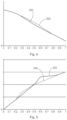
- FIG. 2 shows schematic courses of thickness setbacks of a conventional rotor blade and of a rotor blade with a local minimum of the course of the lift coefficient in the middle portion;
- FIG. 3 shows schematic courses of blade depths of a conventional rotor blade and of a rotor blade with a local minimum of the course of the lift coefficient in the middle portion;
- FIG. 4 shows schematic profiles of blade thicknesses of a conventional rotor blade and of a rotor blade with a local minimum of the profile of the lift coefficient in the middle portion;
- FIG. 5 shows schematic courses of lift-to-drag performances of a conventional rotor blade and of a rotor blade with a local minimum of the course of the lift coefficient in the middle portion.
- FIG. 1 shows a schematic three-dimensional view of an exemplary embodiment of a wind turbine 100 .
- the wind turbine 100 has a tower 102 and a nacelle 104 on the tower 102 .
- An aerodynamic rotor 106 having three rotor blades 108 , which each have a rotor blade length R, and a spinner 110 are provided on the nacelle 104 .
- the aerodynamic rotor 106 is set into a rotational movement by the wind and therefore also rotates an electrodynamic rotor or runner of a generator which is coupled directly or indirectly to the aerodynamic rotor 106 .
- the electric generator is arranged in the nacelle 104 and generates electrical energy.
- the pitch angles of the rotor blades 108 can be changed by pitch motors at the rotor blade roots of the respective rotor blades 108 .
- the rotor blades 108 each have a hub portion 108 a , a middle portion 108 b and a tip portion 108 c .
- the hub portion 108 a faces a hub arranged on the nacelle 104 .
- the tip portion 108 c is the distal portion of the rotor blade 108 and faces away from the hub and the nacelle 104 .
- the tip portion 108 c extends from a blade tip 109 in the direction of the hub.
- the middle portion 108 b is arranged between the hub portion 108 a and the tip portion 108 c.
- the rotor blades 108 have a profile in the longitudinal direction.
- the profile sections therefore change over the longitudinal direction of a rotor blade.
- the profile is distinguished by a plurality of a lift coefficients.
- the relative thickness of the rotor blades 108 is between 20% and 30% in the respective middle portion 108 b .
- the lift coefficients are smaller in the middle portion 108 b than in the hub portion 108 a and smaller than in the tip portion 108 c .
- a lift coefficient is understood here as meaning a design lift coefficient.
- FIG. 2 shows schematic courses of thickness setbacks of a conventional rotor blade and of a rotor blade with a local minimum of the plurality of the lift coefficients in the middle portion.
- the relative rotor blade length is plotted between 0 and 1, or between 0% and 100%.
- the thickness setback is plotted on the ordinate.
- the first course of a thickness setback 200 represents the course of a thickness setback of a conventional rotor blade.
- the thickness setback 200 of the conventional rotor blade decreases from 0.5 in the region close to the hub to a value of approx. 0.4 and is then virtually constant between 30% and 100% of the relative rotor blade length.
- a course of a thickness setback 202 of a rotor blade changes to a more pronounced extent along the relative rotor blade length.
- the thickness setback is greatly reduced between 0% and 30% of the relative rotor blade length.
- the course of the thickness setback 202 comprises a minimum 206 . From the minimum 206 at 30% of the relative rotor blade length, the course of the thickness setback 202 of the rotor blade 108 increases to a local maximum 208 at approx. 60% of the relative rotor blade length. From the maximum 208 , which is at approx.
- the course of the thickness setback 202 decreases between 60% and 90% of the relative rotor blade length. Between 90% and 100% of the relative rotor blade length, the course of the thickness setback 202 is substantially constant. At 90% of the relative rotor blade length, there is a local minimum of the course of the thickness setback 202 .
- the course of the thickness setback 202 over the rotor blade length is S-shaped, that is to say initially comprises a local minimum 206 and then a local maximum 208 between blade connector and blade tip.
- FIG. 3 shows schematic courses of blade depth of a conventional rotor blade and of a rotor blade 108 with a local minimum of the lift coefficient in the middle portion.
- the relative rotor blade length of between 0 and 1, or between 0% and 100%, is also plotted here.
- the chord length of rotor blades is plotted qualitatively on the abscissa.
- the course of the chord length 210 represents the chord length of a conventional rotor blade.
- the course of the chord length 212 represents the course of a chord length of a rotor blade.
- chord length in a range 214 of between 30% and 80% of the relative rotor blade length is greater than in the case of conventional rotor blades.
- this rotor blade 108 can be provided with a greater profile thickness, with nevertheless a constant relative profile thickness being achieved. Owing thereto, the lift-to-drag performance of the rotor blade 108 in the middle portion 108 b , in particular in the range 214 , with the course of the chord length 212 can be improved.
- FIG. 4 shows schematic courses of blade thicknesses of a conventional rotor blade and of a rotor blade 108 with a local minimum of the lift coefficient in the middle portion.
- the relative rotor blade length of between 0 and 1, or between 0% and 100%, is also plotted here.
- the course of the blade thickness 220 represents the course of the blade thickness of a conventional rotor blade.
- the course of the blade thickness 222 represents the course of a rotor blade 108 . It is apparent that the blade thickness 222 in a range of between 30% and 80% of the relative rotor blade length is greater than in the case of the conventional rotor blade. Consequently, with the greater chord length, shown in FIG. 3 , in said rotor blade portion, a substantially consistent relative thickness can be achieved and nevertheless an increased lift-to-drag performance can be obtained.
- FIG. 5 shows schematic courses of lift-to-drag performances of a conventional rotor blade and of a rotor blade 108 with a local minimum of the lift coefficient in the middle portion.
- the relative rotor blade length of between 0 and 1, or between 0% and 100%, is again plotted.
- the lift-to-drag performance is plotted qualitatively on the ordinate.
- the profile of the lift-to-drag performance 230 represents the course of a lift-to-drag performance of a conventional rotor blade.
- the course of the lift-to-drag performance 232 represents the course of a lift-to-drag performance of a rotor blade 108 .
- the lift-to-drag performance 232 in two portions is significantly higher than the lift-to-drag performance of the conventional rotor blade.
- increases in the lift-to-drag performance can be achieved by a greater chord length, a greater profile thickness and a reduced lift coefficient being realized.
Applications Claiming Priority (3)
| Application Number | Priority Date | Filing Date | Title |
|---|---|---|---|
| DE102019119027.4 | 2019-07-12 | ||
| DE102019119027.4A DE102019119027B4 (de) | 2019-07-12 | 2019-07-12 | Rotorblatt und Windenergieanlage |
| PCT/EP2020/069269 WO2021008972A1 (de) | 2019-07-12 | 2020-07-08 | Rotorblatt und windenergieanlage |
Publications (2)
| Publication Number | Publication Date |
|---|---|
| US20220252044A1 US20220252044A1 (en) | 2022-08-11 |
| US11828262B2 true US11828262B2 (en) | 2023-11-28 |
Family
ID=71575390
Family Applications (1)
| Application Number | Title | Priority Date | Filing Date |
|---|---|---|---|
| US17/626,384 Active 2040-11-23 US11828262B2 (en) | 2019-07-12 | 2020-07-08 | Rotor blade and wind turbine |
Country Status (5)
| Country | Link |
|---|---|
| US (1) | US11828262B2 (de) |
| EP (1) | EP3997330A1 (de) |
| CN (1) | CN114127411A (de) |
| DE (1) | DE102019119027B4 (de) |
| WO (1) | WO2021008972A1 (de) |
Families Citing this family (2)
| Publication number | Priority date | Publication date | Assignee | Title |
|---|---|---|---|---|
| WO2023126041A1 (en) * | 2021-12-28 | 2023-07-06 | Vestas Wind Systems A/S | Wind turbine |
| WO2024028521A1 (es) * | 2022-08-03 | 2024-02-08 | Nabrawind Technologies, S.L. | Metodo de obtencion de una pala segmentada mejorada |
Citations (11)
| Publication number | Priority date | Publication date | Assignee | Title |
|---|---|---|---|---|
| US20070036657A1 (en) * | 2003-04-28 | 2007-02-15 | Aloys Wobben | Rotor blade for a wind power system |
| DE102008052858A1 (de) | 2008-10-23 | 2010-04-29 | Repower Systems Ag | Profil eines Rotorblatts und Rotorblatt einer Windenergieanlage |
| EP2284389A2 (de) | 2002-06-05 | 2011-02-16 | Aloys Wobben | Windenergieanlage |
| US20120070299A1 (en) | 2009-05-18 | 2012-03-22 | Lm Glasfiber A/S | Wind turbine blade |
| US20120280509A1 (en) * | 2011-02-28 | 2012-11-08 | Mitsubishi Heavy Industries, Ltd. | Wind turbine blade and wind turbine generator including the same |
| DE202013004881U1 (de) | 2013-05-17 | 2013-06-13 | Michael Dienst | Fluiddynamisch wirksames Strömungsprofil aus geometrischen Grundfiguren |
| DE102012206109B3 (de) | 2012-04-13 | 2013-09-12 | Wobben Properties Gmbh | Rotorblatt einer Windenergieanlage |
| US20130272890A1 (en) * | 2010-10-22 | 2013-10-17 | Mitsubishi Heavy Industries, Ltd | Wind turbine blade, wind turbine generator including wind turbine blade, and method for designing wind turbine blade |
| DE102013202666A1 (de) | 2013-02-19 | 2014-08-21 | Senvion Se | Rotorblatt einer Windenergieanlage |
| EP3343024A1 (de) | 2010-10-22 | 2018-07-04 | Mitsubishi Heavy Industries, Ltd. | Windturbinenblatt, windturbinengenerator damit und entwurfsverfahren dafür |
| DE102017124861A1 (de) | 2017-10-24 | 2019-04-25 | Wobben Properties Gmbh | Rotorblatt einer Windenergieanlage und Verfahren zu dessen Auslegung |
Family Cites Families (4)
| Publication number | Priority date | Publication date | Assignee | Title |
|---|---|---|---|---|
| EP2031241A1 (de) * | 2007-08-29 | 2009-03-04 | Lm Glasfiber A/S | Rotorschaufel einer Windturbine mit Barriereerzeugungsvorrichtung |
| US8197218B2 (en) * | 2007-11-08 | 2012-06-12 | Alliance For Sustainable Energy, Llc | Quiet airfoils for small and large wind turbines |
| EP2107235A1 (de) * | 2008-04-02 | 2009-10-07 | Lm Glasfiber A/S | Windturbinenschaufel mit Hilfsrotorblatt |
| EP2253834A1 (de) * | 2009-05-18 | 2010-11-24 | Lm Glasfiber A/S | Windturbinenschaufel mit Flusswechselelementen |
-
2019
- 2019-07-12 DE DE102019119027.4A patent/DE102019119027B4/de active Active
-
2020
- 2020-07-08 EP EP20739339.8A patent/EP3997330A1/de active Pending
- 2020-07-08 CN CN202080050783.8A patent/CN114127411A/zh active Pending
- 2020-07-08 WO PCT/EP2020/069269 patent/WO2021008972A1/de unknown
- 2020-07-08 US US17/626,384 patent/US11828262B2/en active Active
Patent Citations (16)
| Publication number | Priority date | Publication date | Assignee | Title |
|---|---|---|---|---|
| EP2284389A2 (de) | 2002-06-05 | 2011-02-16 | Aloys Wobben | Windenergieanlage |
| US20070036657A1 (en) * | 2003-04-28 | 2007-02-15 | Aloys Wobben | Rotor blade for a wind power system |
| DE102008052858A1 (de) | 2008-10-23 | 2010-04-29 | Repower Systems Ag | Profil eines Rotorblatts und Rotorblatt einer Windenergieanlage |
| US8814525B2 (en) | 2008-10-23 | 2014-08-26 | Senvion Se | Profile of a rotor blade and rotor blade of a wind power plant |
| US20120070299A1 (en) | 2009-05-18 | 2012-03-22 | Lm Glasfiber A/S | Wind turbine blade |
| EP3343024A1 (de) | 2010-10-22 | 2018-07-04 | Mitsubishi Heavy Industries, Ltd. | Windturbinenblatt, windturbinengenerator damit und entwurfsverfahren dafür |
| US20130272890A1 (en) * | 2010-10-22 | 2013-10-17 | Mitsubishi Heavy Industries, Ltd | Wind turbine blade, wind turbine generator including wind turbine blade, and method for designing wind turbine blade |
| US20120280509A1 (en) * | 2011-02-28 | 2012-11-08 | Mitsubishi Heavy Industries, Ltd. | Wind turbine blade and wind turbine generator including the same |
| US9759185B2 (en) * | 2012-04-13 | 2017-09-12 | Wobben Properties Gmbh | Rotor blade for a wind power plant |
| DE102012206109B3 (de) | 2012-04-13 | 2013-09-12 | Wobben Properties Gmbh | Rotorblatt einer Windenergieanlage |
| US20150064017A1 (en) | 2012-04-13 | 2015-03-05 | Wobben Properties Gmbh | Rotor blade for a wind power plant |
| DE102013202666A1 (de) | 2013-02-19 | 2014-08-21 | Senvion Se | Rotorblatt einer Windenergieanlage |
| US9932960B2 (en) | 2013-02-19 | 2018-04-03 | Senvion Gmbh | Rotor blade of a wind turbine |
| DE202013004881U1 (de) | 2013-05-17 | 2013-06-13 | Michael Dienst | Fluiddynamisch wirksames Strömungsprofil aus geometrischen Grundfiguren |
| DE102017124861A1 (de) | 2017-10-24 | 2019-04-25 | Wobben Properties Gmbh | Rotorblatt einer Windenergieanlage und Verfahren zu dessen Auslegung |
| US20200248671A1 (en) | 2017-10-24 | 2020-08-06 | Wobben Properties Gmbh | Rotor blade of a wind turbine and method for designing same |
Also Published As
| Publication number | Publication date |
|---|---|
| DE102019119027B4 (de) | 2022-04-28 |
| WO2021008972A1 (de) | 2021-01-21 |
| CN114127411A (zh) | 2022-03-01 |
| DE102019119027A1 (de) | 2021-01-14 |
| EP3997330A1 (de) | 2022-05-18 |
| US20220252044A1 (en) | 2022-08-11 |
Similar Documents
| Publication | Publication Date | Title |
|---|---|---|
| EP2834517B1 (de) | Verdrillter schaufelfuss | |
| CN101403368B (zh) | 风力涡轮机转子叶片及可调桨距式风力涡轮机 | |
| US8419373B1 (en) | Wind turbine blade, wind turbine generator equipped with wind turbine blade and method of designing wind turbine blade | |
| EP2129908B1 (de) | Windturbinenschaufel mit wirbelerzeugern | |
| US8944775B2 (en) | Wind turbine blade having a spoiler with effective separation of airflow | |
| US10974818B2 (en) | Vortex generator arrangement for an airfoil | |
| US8794919B2 (en) | Wind turbine blade with variable trailing edge | |
| EP2107235A1 (de) | Windturbinenschaufel mit Hilfsrotorblatt | |
| EP2138714A1 (de) | Windturbinenschaufel mit einer Vorrichtung zur Stromführung mit optimierter Höhe | |
| EP3037656B1 (de) | Rotorblatt mit Wirbelerzeugern | |
| US11828262B2 (en) | Rotor blade and wind turbine | |
| CN102187092B (zh) | 带低进气顶端的风力涡轮机 | |
| KR20160017083A (ko) | 풍력 발전 설비의 로터 블레이드 그리고 풍력 발전 설비 | |
| EP3453872B1 (de) | Verfahren zur abschwächung von lärm an windturbinen bei starkwindbedingungen | |
| EP3431750B1 (de) | Verfahren zur bestimmung der anordnungsposition eines wirbelgenerators an einer windturbinenschaufel, verfahren zur herstellung einer windturbinenschaufelanordnung und windturbinenschaufelanordnung | |
| US20100213721A1 (en) | Wind turbine blade and wind power generator using the same | |
| EP2863052A1 (de) | Windturbinenrotorblatt und Windturbinengenerator | |
| JP5433554B2 (ja) | 風車翼およびこれを備えた風力発電装置ならびに風車翼の設計方法 | |
| US8517690B2 (en) | Double leading edge airfoil for wind turbine blade root | |
| US20220228551A1 (en) | Rotor blade and wind turbine | |
| DK2940292T3 (en) | Device for a rotor blade of a wind turbine | |
| WO2013156479A1 (en) | A wind turbine blade having an angled stall fence |
Legal Events
| Date | Code | Title | Description |
|---|---|---|---|
| FEPP | Fee payment procedure |
Free format text: ENTITY STATUS SET TO UNDISCOUNTED (ORIGINAL EVENT CODE: BIG.); ENTITY STATUS OF PATENT OWNER: LARGE ENTITY |
|
| AS | Assignment |
Owner name: WOBBEN PROPERTIES GMBH, GERMANY Free format text: ASSIGNMENT OF ASSIGNORS INTEREST;ASSIGNORS:MOELLER, CHRISTIAN;MAASS, HAUKE;STEMBERG, JOCHEN;SIGNING DATES FROM 20220304 TO 20220314;REEL/FRAME:059716/0970 |
|
| STPP | Information on status: patent application and granting procedure in general |
Free format text: DOCKETED NEW CASE - READY FOR EXAMINATION |
|
| STPP | Information on status: patent application and granting procedure in general |
Free format text: NOTICE OF ALLOWANCE MAILED -- APPLICATION RECEIVED IN OFFICE OF PUBLICATIONS |
|
| STPP | Information on status: patent application and granting procedure in general |
Free format text: AWAITING TC RESP., ISSUE FEE NOT PAID |
|
| STPP | Information on status: patent application and granting procedure in general |
Free format text: NOTICE OF ALLOWANCE MAILED -- APPLICATION RECEIVED IN OFFICE OF PUBLICATIONS |
|
| STPP | Information on status: patent application and granting procedure in general |
Free format text: PUBLICATIONS -- ISSUE FEE PAYMENT VERIFIED |
|
| STCF | Information on status: patent grant |
Free format text: PATENTED CASE |