US11735955B2 - Resonant circuit for transmitting electric energy - Google Patents
Resonant circuit for transmitting electric energy Download PDFInfo
- Publication number
- US11735955B2 US11735955B2 US16/754,341 US201816754341A US11735955B2 US 11735955 B2 US11735955 B2 US 11735955B2 US 201816754341 A US201816754341 A US 201816754341A US 11735955 B2 US11735955 B2 US 11735955B2
- Authority
- US
- United States
- Prior art keywords
- transmitter
- recited
- tank circuit
- coil
- receiver
- Prior art date
- Legal status (The legal status is an assumption and is not a legal conclusion. Google has not performed a legal analysis and makes no representation as to the accuracy of the status listed.)
- Active, expires
Links
Images


Classifications
-
- H—ELECTRICITY
- H02—GENERATION; CONVERSION OR DISTRIBUTION OF ELECTRIC POWER
- H02J—CIRCUIT ARRANGEMENTS OR SYSTEMS FOR SUPPLYING OR DISTRIBUTING ELECTRIC POWER; SYSTEMS FOR STORING ELECTRIC ENERGY
- H02J50/00—Circuit arrangements or systems for wireless supply or distribution of electric power
- H02J50/10—Circuit arrangements or systems for wireless supply or distribution of electric power using inductive coupling
- H02J50/12—Circuit arrangements or systems for wireless supply or distribution of electric power using inductive coupling of the resonant type
-
- H—ELECTRICITY
- H01—ELECTRIC ELEMENTS
- H01F—MAGNETS; INDUCTANCES; TRANSFORMERS; SELECTION OF MATERIALS FOR THEIR MAGNETIC PROPERTIES
- H01F27/00—Details of transformers or inductances, in general
- H01F27/24—Magnetic cores
-
- H—ELECTRICITY
- H01—ELECTRIC ELEMENTS
- H01F—MAGNETS; INDUCTANCES; TRANSFORMERS; SELECTION OF MATERIALS FOR THEIR MAGNETIC PROPERTIES
- H01F27/00—Details of transformers or inductances, in general
- H01F27/28—Coils; Windings; Conductive connections
-
- H—ELECTRICITY
- H01—ELECTRIC ELEMENTS
- H01F—MAGNETS; INDUCTANCES; TRANSFORMERS; SELECTION OF MATERIALS FOR THEIR MAGNETIC PROPERTIES
- H01F38/00—Adaptations of transformers or inductances for specific applications or functions
- H01F38/14—Inductive couplings
-
- H—ELECTRICITY
- H02—GENERATION; CONVERSION OR DISTRIBUTION OF ELECTRIC POWER
- H02J—CIRCUIT ARRANGEMENTS OR SYSTEMS FOR SUPPLYING OR DISTRIBUTING ELECTRIC POWER; SYSTEMS FOR STORING ELECTRIC ENERGY
- H02J50/00—Circuit arrangements or systems for wireless supply or distribution of electric power
- H02J50/40—Circuit arrangements or systems for wireless supply or distribution of electric power using two or more transmitting or receiving devices
-
- H—ELECTRICITY
- H02—GENERATION; CONVERSION OR DISTRIBUTION OF ELECTRIC POWER
- H02J—CIRCUIT ARRANGEMENTS OR SYSTEMS FOR SUPPLYING OR DISTRIBUTING ELECTRIC POWER; SYSTEMS FOR STORING ELECTRIC ENERGY
- H02J7/00—Circuit arrangements for charging or depolarising batteries or for supplying loads from batteries
- H02J7/02—Circuit arrangements for charging or depolarising batteries or for supplying loads from batteries for charging batteries from ac mains by converters
Definitions
- the present invention relates to an apparatus for transmitting electrical energy to at least one electrical consumer, for example a rechargeable battery, comprising at least one transmitter device for transmitting an electrical energy having at least one first coil and at least one first capacitor for producing a resonant tank circuit at the transmitter device, at least one receiver device for receiving the energy transmitted by the transmitter device, comprising at least one second coil and at least one second capacitor for producing a resonant tank circuit at the receiver device, wherein the receiver device is connectable to the consumer to form an electrical connection, a power amplifier, a transformer for matching the impedance between the resonant tank circuit at the receiver device and the consumer, and an electrical energy source, in particular an AC voltage source, for supplying the resonant tank circuit at the transmitter device with electrical energy.
- a power amplifier for matching the impedance between the resonant tank circuit at the receiver device and the consumer
- an electrical energy source in particular an AC voltage source
- the present invention provides an apparatus for transmitting electrical energy to at least one electrical consumer, for example a rechargeable battery, comprising at least one transmitter device for transmitting an electrical energy having at least one first coil and at least one first capacitor for producing a resonant tank circuit at the transmitter device, at least one receiver device for receiving the energy transmitted by the transmitter device, comprising at least one second coil and at least one second capacitor for producing a resonant tank circuit at the receiver device, wherein the receiver device is connectable to the consumer to form an electrical connection, a power amplifier, a transformer for matching the impedance between the resonant tank circuit at the receiver device and the consumer, and an electrical energy source, in particular an AC voltage source, for supplying the resonant tank circuit at the transmitter device with electrical energy.
- a power amplifier for matching the impedance between the resonant tank circuit at the receiver device and the consumer
- an electrical energy source in particular an AC voltage source
- the invention provides for the transmitter device and the receiver device jointly to form a series resonant tank circuit for transferring the electrical energy from the transmitter device to the receiver device, such that at the receiver device the electrical energy made available by the transmitter device can be fed to the consumer. As a result, electrical energy can be transferred in an efficient way.
- the consumer can be configured in the form of a load, an electrical resistor, a storage device, an energy store, a convertor or in the form of other components that can make the energy fed useable for their function.
- the invention is based on the principle of inductive coupling with two resonant high-efficiency resonance tank circuits, wherein a first tank circuit is fed with correspondingly high-frequency energy such that the high-frequency energy is transferred to the second tank circuit in order to make it available to an electrical consumer. Since the first tank circuit is highly resonant, the electrical energy situated in the tank circuit decreases only relatively slowly over many oscillation cycles. The electrical energy is taken up by the second tank circuit, however, if the two tank circuits do not exceed a predetermined distance with respect to one another.
- the transformer can also be referred to as a matching transformer.
- the resonant tank circuit can also be referred to as a resonance circuit.
- the power amplifier serves as a clock generator for the frequency of the resonant tank circuit at the transmitter device.
- the power amplifier is configured such that either a low-impedance or a high-impedance energy source is produced for the resonant tank circuit at the transmitter device.
- the second coil and the second capacitor of the receiver device can be connected in series with one another in order to produce a series resonant tank circuit at the receiver device.
- a high electrical voltage value and a low electrical current value can be generated at the transmitter device.
- This arrangement is advantageous particularly in the case of a high-impedance energy source for supplying the transmitter device.
- the second coil and the second capacitor of the receiver device can be connected in parallel with one another in order to produce a parallel resonant tank circuit at the receiver device.
- the parallel resonant tank circuit at the receiver device has a high impedance in this case.
- the first coil and the first capacitor of the transmitter device can be connected in series with one another in order to produce a series resonant tank circuit at the transmitter device.
- a higher voltage value and at the same time a low current value can be generated at the receiver device and an energy loss at the second coil of the receiver device can be reduced as a result.
- both the first and the second coil can contain a ferrite core having a resistivity of 10 5 to 10 6 ⁇ m and also a magnetic permeability of 50 to 500, in particular 125.
- the resonant tank circuit at the receiver device can be produced in an efficient manner, with the result that a high amount of energy can be transmitted from the transmitter device to the receiver device.
- the ferrite core at least partly to contain nickel-zinc alloy (NiZn).
- NiZn nickel-zinc alloy
- the ferrite core can also be possible for the ferrite core to be configured in a U-shaped fashion and to have a cross-sectional area of 5.65 cm 2 , such that a power density of 35 W/cm 2 , for an input power of 200 W, is achievable during the transfer of the electrical energy from the transmitter device to the receiver device.
- the resonant tank circuit at the receiver device can be produced in an efficient manner, with the result that a high amount of energy can be transmitted from the transmitter device to the receiver device.
- the frequency of the resonant tank circuit at the transmitter device can be between 2 and 30 MHz, in particular between 6.765 and 6.795 MHz, for example to be 6.78 MHz.
- the resonant tank circuit at the receiver device can be produced in an efficient manner, with the result that a high amount of energy can be transmitted from the transmitter device to the receiver device.
- the transmitter device and/or the receiver device can comprise a variable capacitor, for example a trimmer capacitor.
- the transmitter device and/or the receiver device can also comprise, instead of a trimmer capacitor, an adequately acting electronic circuit for tuning the resonant frequency.
- the receiver device can comprise a transformer for increasing the efficiency by impedance matching and also for decoupling between the resonant tank circuit at the receiver device and the consumer.
- the transformer can also be configured as an integrated transformer.
- the transformer can be integrated as an additional winding concomitantly on the resonant tank circuit at the receiver device.
- the ferrite core of the first coil and/or the second coil can be configured in a wide variety of shapes.
- the incorporation of the apparatus according to the invention in a housing can be adapted to specific geometric stipulations and in particular to a possible space deficiency.
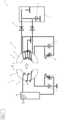
- FIG. 1 shows a schematic circuit diagram in accordance with a first embodiment according to the invention, wherein a transmitter device comprises a series tank circuit and a receiver device comprises a series tank circuit, with connection of a transformer with a center tap and a rectifier as double-pulse center-tap rectifier;
- FIG. 2 shows a schematic circuit diagram in accordance with a second embodiment according to the invention, wherein the transmitter device comprises a parallel tank circuit and the receiver device comprises a series tank circuit, with connection of a transformer with a center tap and a rectifier as double-pulse center-tap rectifier;
- FIG. 3 shows a schematic circuit diagram in accordance with a third embodiment according to the invention, wherein the transmitter device comprises a series tank circuit and the receiver device comprises a parallel tank circuit, with connection of a transformer with a center tap and a rectifier as double-pulse center-tap rectifier;
- FIG. 4 shows a schematic circuit diagram in accordance with a fourth embodiment according to the invention, wherein the transmitter device comprises a parallel tank circuit and the receiver device comprises a parallel tank circuit, with connection of a transformer with a center tap and a rectifier as double-pulse center-tap rectifier;
- FIG. 5 shows a schematic circuit diagram in accordance with a fifth embodiment according to the invention, wherein the transmitter device comprises a series tank circuit and the receiver device comprises a series tank circuit, a transformer with a bridge rectifier and without a center tap being provided in the receiver device;
- FIG. 6 shows a schematic circuit diagram in accordance with a sixth embodiment according to the invention, comprising a bridge rectifier, and a coil of the receiver device comprising the transformer;
- FIG. 7 shows a schematic circuit diagram in accordance with a seventh embodiment according to the invention, comprising a double-pulse center-tap rectifier and an integrated transformer;
- FIG. 8 shows a schematic circuit diagram in accordance with an eighth embodiment according to the invention, comprising a load in the form of an electrical resistor
- FIG. 9 shows a ferrite core of the first and/or the second coil in a first configuration
- FIG. 10 shows the ferrite core of the first and/or the second coil in a second configuration
- FIG. 11 shows the ferrite core of the first and/or the second coil in a third configuration
- FIG. 12 shows the ferrite core of the first and/or the second coil in a fourth configuration
- FIG. 13 shows the ferrite core of the first and/or the second coil in a fifth configuration
- FIG. 14 shows the ferrite core of the first and/or the second coil in a sixth configuration with a first winding arrangement
- FIG. 15 shows the ferrite core of the first and/or the second coil in the sixth configuration with a second winding arrangement.
- FIGS. 1 to 8 shows schematic circuit diagrams of the apparatus 1 according to the invention for transmitting an electrical energy from a transmitter device 2 to a receiver device 3 in accordance with various exemplary embodiments.
- the apparatus 1 substantially comprises a transmitter device 2 and a receiver device 3 .
- the transmitter device 2 serves for taking up an electrical energy and also for transmitting or transferring an electrical energy to the receiver device 3 .
- the transmitter device 2 is connected to an electrical energy source.
- the supply with electrical energy is effected in the form of an AC source.
- the energy source is not illustrated in the figures.
- the receiver device 3 serves in turn for receiving the transmitted electrical energy, processing and also for forwarding to an electrical consumer 4 .
- the electrical consumer 4 can be configured for example as a rechargeable battery with an integrated rectifier.
- the rectifier serves for converting the AC voltage generated at the receiver device 3 into a DC voltage.
- the consumer 4 merely to be configured as an electrical resistor.
- the electrical consumer 4 configured as a rechargeable battery is connectable to the receiver device 3 optionally and in a re-releasable manner in order to be supplied with electrical current or to charge the rechargeable battery with electrical energy.
- the apparatus 1 according to the invention serves as a charging apparatus for the consumer 4 configured as a rechargeable battery.
- FIG. 1 shows a schematic circuit diagram in accordance with a first embodiment of the apparatus 1 according to the invention.
- the apparatus 1 in this case substantially comprises the transmitter device 2 and the receiver device 3 .
- the transmitter device 2 comprises a first coil 5 and a first capacitor 6 .
- the first coil 5 and the first capacitor 6 are connected in series with one another such that a first resonant tank circuit is formed.
- the first resonant tank circuit is accordingly a series resonant tank circuit.
- This first resonant tank circuit is also referred to as transmitter resonance circuit.
- the transmitter device 2 can comprise a first trimming capacitor 7 , which serves for setting the capacitance or the resonant frequency in the transmitter device 2 .
- the first trimming capacitor 7 can also be referred to as a variable capacitor.
- the receiver device 3 in accordance with the first embodiment of the apparatus 1 according to the invention comprises a second coil 8 and a second capacitor 9 .
- the second coil 8 and the second capacitor 9 are connected in series with one another such that a second resonant tank circuit is formed.
- the second resonant tank circuit is accordingly a series resonant tank circuit.
- This second resonant tank circuit is also referred to as receiver resonance circuit.
- the receiver device 3 can comprise a second trimming capacitor 10 , which serves for setting the capacitance or the resonant frequency in the receiver device 3 .
- the second trimming capacitor 10 can also be referred to as a variable capacitor.
- the apparatus 1 in accordance with the first embodiment furthermore comprises a rectifier 11 for converting the AC voltage generated at the receiver device 3 into a DC voltage.
- the rectifier 11 is configured as a double-pulse center-tap rectifier.
- the rectifier 11 comprises a double-pulse center-tap connection 12 comprises a first diode 13 and a second diode 14 .
- the double-pulse center-tap connection 12 serves for producing a higher efficiency.
- any other suitable type of rectifier can also be used.
- the first embodiment of the apparatus 1 comprises a transformer 15 connected to the receiver device 3 .
- the transformer 15 serves for matching the electrical voltage and substantially comprises a circular ferrite core 16 in accordance with the embodiments shown in the figures.
- a first winding N 1 is positioned at one side and a second winding N 2 is positioned at a second side.
- the first winding N 1 has a first wire winding number and the second winding N 2 has a second wire winding number.
- the first winding N 1 contains a higher wrapping number than the second winding N 2 .
- FIG. 2 illustrates a schematic circuit diagram of the apparatus 1 according to the invention in accordance with a second embodiment.
- the apparatus 1 in accordance with the second embodiment substantially corresponds to the apparatus 1 in accordance with the first embodiment in FIG. 1 .
- the apparatus 1 in accordance with the second embodiment differs from the apparatus 1 in accordance with the first embodiment in that the first coil 5 and the first capacitor 6 of the transmitter device 2 are connected in parallel with one another, with the result that a parallel resonant tank circuit is produced.
- the receiver device 3 in accordance with the second embodiment of the apparatus 1 according to the invention additionally comprises a second coil 8 and a second capacitor 9 connected in series (i.e. serially) with one another, with the result that a series resonant tank circuit is formed.
- FIG. 3 shows a schematic circuit diagram of the apparatus 1 according to the invention in accordance with a third embodiment.
- the apparatus 1 in accordance with the third embodiment substantially corresponds to the apparatus 1 in accordance with the first or second embodiment in FIG. 1 or FIG. 2 , respectively.
- the apparatus 1 in accordance with the third embodiment differs from the apparatus 1 in accordance with the first or second embodiment in that the first coil 5 and the first capacitor 6 of the transmitter device 2 are connected in series (i.e. serially) with one another, with the result that a series resonant tank circuit is produced.
- the receiver device 3 in accordance with the third embodiment of the apparatus 1 according to the invention additionally comprises a second coil 8 and a second capacitor 9 connected in parallel with one another, with the result that a parallel resonant tank circuit is formed.
- FIG. 4 illustrates a schematic circuit diagram of the apparatus 1 according to the invention in accordance with a fourth embodiment.
- the apparatus 1 in accordance with the fourth embodiment substantially corresponds to the apparatus 1 in accordance with the first, second or third embodiment correspondingly illustrated in FIGS. 1 to 3 .
- the apparatus 1 in accordance with the fourth embodiment differs from the apparatus 1 in accordance with the first, second or third embodiment in that the first coil 5 and the first capacitor 6 of the transmitter device 2 are connected in parallel with one another, with the result that a parallel resonant tank circuit is produced.
- the receiver device 3 in accordance with the second embodiment of the apparatus 1 according to the invention in turn comprises a second coil 8 and a second capacitor 9 connected in parallel with one another, with the result that a parallel resonant tank circuit is formed.
- FIG. 5 illustrates a schematic circuit diagram of the apparatus 1 according to the invention in accordance with a fifth embodiment.
- the apparatus 1 in accordance with the fifth embodiment substantially corresponds to the apparatus 1 in accordance with the third embodiment illustrated in FIG. 3 .
- the rectifier 11 at the receiver device 3 in accordance with the fifth embodiment is configured in the form of a bridge rectifier instead of a double-pulse center-tap rectifier. This does not comprise a center tap at the transformer 15 .
- FIG. 6 illustrates a schematic circuit diagram of the apparatus 1 according to the invention in accordance with a sixth embodiment.
- the apparatus 1 in accordance with the sixth embodiment substantially corresponds to the apparatus 1 in accordance with the first embodiment illustrated in FIG. 1 .
- the receiver device 3 in the apparatus 1 in accordance with the sixth embodiment comprises a transformer 15 without a separate or dedicated ferrite core.
- the ferrite core 20 of the second coil 8 of the receiver device 3 serves as the ferrite core of the transformer 15 .
- the rectifier 11 of the apparatus 1 of the sixth embodiment is configured in the form of a bridge rectifier.
- FIG. 7 illustrates a schematic circuit diagram of the apparatus 1 according to the invention in accordance with a seventh embodiment.
- the apparatus 1 in accordance with the seventh embodiment substantially corresponds to the apparatus 1 in accordance with the sixth embodiment illustrated in FIG. 6 .
- the rectifier 11 of the receiver device 3 in accordance with the seventh embodiment is configured as a double-pulse center-tap rectifier instead of a bridge rectifier.
- FIG. 8 illustrates a schematic circuit diagram of the apparatus 1 according to the invention in accordance with an eighth embodiment.
- the apparatus 1 in accordance with the eighth embodiment substantially corresponds to the apparatus 1 in accordance with the first embodiment illustrated in FIG. 1 .
- the consumer 4 instead of a rectifier 11 is connected to the receiver device 3 .
- the consumer 4 is configured in the form of an electrical resistor.
- the transmitter device 2 comprises a first trimming capacitor 7 and the receiver device 3 comprises a second trimming capacitor 10 .
- the transmitter device 2 comprises a first trimming capacitor 7
- the receiver device 3 comprises a trimming capacitor.
- the transmitter device 2 comprises a first trimming capacitor 7
- the receiver device 3 not to comprise a trimming capacitor.
- the receiver device 3 comprises a trimming capacitor 10
- the transmitter device 2 not to comprise a trimming capacitor.
- neither the transmitter device 2 nor the receiver device 3 to comprise a trimming capacitor.
- the consumer 4 in accordance with the first to seventh embodiments to comprise a capacitor 17 .
- the capacitor 17 can be configured as a ceramic capacitor or as an electrolytic capacitor (ELCA).
- the consumer 4 may comprise two capacitors.
- one of the two capacitors is configured as a ceramic capacitor and the other capacitor is configured as an electrolytic capacitor (ELCA).
- ELCA electrolytic capacitor
- the two capacitors serve for smoothing the radio frequency and as a buffer for compensating for possible current fluctuations.
- the wire material used for the construction of the coils and transformers must be RF-suitable (i.e. suitable for a radio frequency).
- RF-suitable i.e. suitable for a radio frequency
- correspondingly suitable litz wires or other suitable materials having an adequate behavior and purpose of use should be selected.
- the first coil 5 comprises a ferrite core 18 consisting of nickel-zinc (NiZn) having a resistivity of 10 5 to 10 6 ⁇ m and a magnetic permeability of 125.
- NiZn nickel-zinc
- the magnetic permeability it is also possible, in accordance with further embodiments, for the magnetic permeability to be between 50 and 500, or in particular between 80 and 200.
- the second coil 8 also comprises a ferrite core 20 consisting of nickel-zinc (NiZn) likewise having a resistivity of 10 5 to 10 6 ⁇ m and a magnetic permeability of 125.
- NiZn nickel-zinc
- the ferrite core 18 of the first coil 5 and the ferrite core 20 of the second coil 8 are configured in a U-shaped fashion and have a cross-sectional area of 5.65 cm 2 , with the result that a power density of 35 W/cm 2 for an input power of 200 W is achieved during the transfer of the electrical energy.
- the ferrite core 18 of the first coil 5 and the ferrite core 20 of the second coil 8 can be configured in various shapes.
- the ferrite core 18 of the first coil 5 and the ferrite core 20 of the second coil 8 are always arranged with respect to one another in the apparatus 1 according to the invention such that the field emission of the respective ferrite core 18 , 20 is directed relative to one another.
- the ferrite core 18 , 20 of the first and/or second coil 5 , 8 in accordance with a first configuration is configured in a U-shape.
- a wire 30 for the winding of a coil is wound around the respective ferrite core 18 , 20 .
- FIG. 10 shows the ferrite core 18 , 20 in accordance with a second configuration.
- the ferrite core 18 , 20 in accordance with the second configuration substantially comprises a base web 41 , from which a first and a second web 42 , 43 extend perpendicular to the base web 41 at the respective ends 41 a , 41 b of the base web 41 .
- a third web 44 extends perpendicular to the base web 41 .
- the first, second and third webs 42 , 43 , 44 extend in the same direction A.
- the third web 44 has a round cross section.
- the second and third webs 42 , 43 have a rectangular cross section.
- FIG. 11 shows the ferrite core 18 , 20 in accordance with a third configuration.
- the ferrite core 18 , 20 in accordance with the third configuration has a curved shape and in this case is configured such that it is substantially straighter than in the first configuration.
- FIG. 12 shows the ferrite core 18 , 20 in accordance with a fourth configuration.
- the ferrite core 18 , 20 in accordance with the fourth configuration substantially comprises a base web 51 , from which a first web 52 and a second web 53 extend perpendicular to the main web 51 in direction A at the respective ends 51 a , 51 b of the base web 51 .
- the first and second webs 52 , 53 have a circular cross section.
- FIG. 13 shows the ferrite core 18 , 20 in accordance with a fifth configuration.
- the ferrite core 18 , 20 in accordance with the fifth configuration substantially comprises a base web 61 , from which a first web 62 and a second web 63 extend perpendicular to the main web 61 in direction A at the respective ends 61 a , 61 b of the base web 61 .
- the first and second webs 62 , 63 have a rectangular cross section.
- FIG. 14 shows the ferrite core 18 , 20 in accordance with a sixth configuration.
- the ferrite core 18 , 20 in accordance with the sixth configuration comprises a baseplate 71 having a cylindrical elevation 72 in the center M.
- a first arcuate elevation 73 is positioned at a first end 71 a of the baseplate 71 and a second arcuate elevation 74 is positioned at a second end 71 b of the baseplate 71 .
- the first and second elevations 73 , 74 are arranged on the baseplate 71 such that the respective concave surfaces of the two arcuate elevations 73 , 74 are directed toward one another.
- the cylindrical elevation on the baseplate 71 is positioned between the two arcuate elevations 73 , 74 . All three elevations 72 , 73 , 74 extend from the baseplate 71 in the same direction A. As evident in FIG. 14 , the wire 30 for the winding of a coil is wound in accordance with a first winding arrangement around the cylindrical elevation in the center M.
- FIG. 15 illustrates the ferrite core 18 , 20 in accordance with the sixth configuration.
- the wire 30 for the winding of a coil is wound spirally in accordance with a second winding arrangement on the baseplate 71 .
- the wire 30 for the winding of a coil is arranged in only one plane or alternatively in a plurality of planes, i.e. a plurality of layers of wire 30 one above another.
- a monolayer arrangement of the windings, subdivided into a plurality of groups, is also possible here in order for example to reduce parasitic winding capacitances.
- a distance D extends between the first coil 5 of the transmitter device 2 and the second coil 8 of the receiver device 3 .
- the distance D is approximately 40 mm.
- a power amplifier 80 at the transmitter device 2 serves here as a clock generator for the frequency of the resonant tank circuit at the transmitter device 2 .
- the power amplifier is connected to an AC voltage source for this purpose.
- the AC voltage source which can also be referred to as current source or voltage source, is not illustrated and is merely indicated by P IN in the figures.
- the power amplifier 80 can be configured so as to produce together with the AC voltage source either a low-impedance or a high-impedance energy resource at the transmitter device 2 for the resonant tank circuit at the transmitter device 2 .
- electrical energy in the form of AC current is then passed from the AC voltage source P IN via the power amplifier 80 with a frequency of 6.78 MHz into the first coil 5 .
- the first coil 5 and the first capacitor 6 produce a resonant tank circuit having an inductance of 1.58 pH and an electrical capacitance of 349 ⁇ 10 ⁇ 12 F.
- the electrical energy situated in this tank circuit decreases only relatively slowly over a high number of cycles.
- the arrangement according to the invention of the transmitter device 2 with respect to the receiver device 3 a relatively large portion of the electrical energy can be transferred from the resonant tank circuit at the transmitter device 2 to the resonant tank circuit at the receiver device 3 .
- the coupled electric fields of the at the two coils 5 , 8 are so-called non-radiative near fields, which can also be referred to as evanescent waves.
- the distance between the coils 5 , 8 is chosen such that it is within the spacing of 1 ⁇ 4 wavelengths, a large portion of the electrical energy is transmitted, i.e. with only low losses, from the first coil 5 of the transmitter device 2 to the second coil 8 of the receiver device 3 .
- a typical output voltage range is between 3 V DC (DC voltage) and 500 V DC (DC voltage).
Abstract
Description
Claims (19)
Applications Claiming Priority (4)
| Application Number | Priority Date | Filing Date | Title |
|---|---|---|---|
| EP17199857.8A EP3346579A1 (en) | 2017-11-03 | 2017-11-03 | Resonant circuit for energy transfer |
| EP17199857.8 | 2017-11-03 | ||
| EP17199857 | 2017-11-03 | ||
| PCT/EP2018/079249 WO2019086319A1 (en) | 2017-11-03 | 2018-10-25 | Resonant circuit for transmitting electric energy |
Publications (2)
| Publication Number | Publication Date |
|---|---|
| US20200336011A1 US20200336011A1 (en) | 2020-10-22 |
| US11735955B2 true US11735955B2 (en) | 2023-08-22 |
Family
ID=60262766
Family Applications (1)
| Application Number | Title | Priority Date | Filing Date |
|---|---|---|---|
| US16/754,341 Active 2039-05-15 US11735955B2 (en) | 2017-11-03 | 2018-10-25 | Resonant circuit for transmitting electric energy |
Country Status (5)
| Country | Link |
|---|---|
| US (1) | US11735955B2 (en) |
| EP (2) | EP3346579A1 (en) |
| JP (1) | JP2020537483A (en) |
| CN (1) | CN111279579A (en) |
| WO (1) | WO2019086319A1 (en) |
Families Citing this family (2)
| Publication number | Priority date | Publication date | Assignee | Title |
|---|---|---|---|---|
| EP3346580A1 (en) * | 2017-11-03 | 2018-07-11 | Hilti Aktiengesellschaft | Resonant oscillating circuit for the transmission of electrical energy without power amplifier |
| DE102021127900A1 (en) | 2021-10-27 | 2023-04-27 | Miele & Cie. Kg | Built-in home appliance system |
Citations (39)
| Publication number | Priority date | Publication date | Assignee | Title |
|---|---|---|---|---|
| JPH02179232A (en) | 1988-12-28 | 1990-07-12 | Toshiba Corp | Photo mediation system power transmission method |
| JPH11243024A (en) | 1998-02-25 | 1999-09-07 | Kyocera Corp | Electrical equipment applicable to non-contact charger |
| US20030030530A1 (en) * | 2001-07-10 | 2003-02-13 | Friwo Geraetebau Gmbh | Charging unit for a contactless transfer of electric power as well as a power absorbing device and a charging system |
| JP2003250233A (en) | 2002-02-25 | 2003-09-05 | Matsushita Electric Works Ltd | Non-contact power transmission apparatus |
| WO2006022365A1 (en) | 2004-08-27 | 2006-03-02 | Hokushin Denki Co., Ltd. | Non-contact power transmission device |
| EP2031731A1 (en) | 2007-09-01 | 2009-03-04 | MAQUET GmbH & Co. KG | Method and device for transferring energy and data wirelessly between a source device and at least one target device |
| US20090058190A1 (en) | 2007-08-31 | 2009-03-05 | Katsuyuki Tanaka | Power receiving device and power transfer system |
| US20090085408A1 (en) | 2007-09-01 | 2009-04-02 | Maquet Gmbh & Co. Kg | Apparatus and method for wireless energy and/or data transmission between a source device and at least one target device |
| US20100187913A1 (en) | 2008-08-20 | 2010-07-29 | Smith Joshua R | Wireless power transfer apparatus and method thereof |
| US20100312310A1 (en) | 2007-10-30 | 2010-12-09 | Werner Meskens | Power link for implantable devices |
| EP2306617A1 (en) | 2009-10-05 | 2011-04-06 | Sony Corporation | Power transmission apparatus, power reception apparatus and power transmission system |
| CN102201702A (en) | 2010-03-10 | 2011-09-28 | 滑动环及设备制造有限公司 | Method for compensating for system tolerances in inductive couplers |
| US20110304216A1 (en) * | 2010-06-10 | 2011-12-15 | Access Business Group International Llc | Coil configurations for inductive power transer |
| JP2012023957A (en) | 2009-07-22 | 2012-02-02 | Tdk Corp | Wireless power supply device and wireless power transmission system |
| CN202206194U (en) | 2011-06-09 | 2012-04-25 | 东南大学 | Wireless energy transmitting apparatus |
| JP2012110154A (en) | 2010-11-18 | 2012-06-07 | Toshiba Corp | Wireless power transmission device |
| JP2012139011A (en) | 2010-12-27 | 2012-07-19 | Contec Co Ltd | Secondary power reception circuit of non-contact power supply facility |
| US20120223585A1 (en) | 2011-03-01 | 2012-09-06 | Tdk Corporation | Wireless power feeder |
| US20130176653A1 (en) * | 2012-01-11 | 2013-07-11 | Samsung Electronics Co., Ltd. | Over-voltage protection device for resonant wireless power reception device and method for controlling the over-voltage protection device |
| US20130223640A1 (en) | 2011-09-28 | 2013-08-29 | Tdk Corporation | Headphone, headphone stand and headphone system |
| US20130234529A1 (en) * | 2012-03-08 | 2013-09-12 | Hitachi Maxell, Ltd. | Wireless power transfer apparatus and wireless power transfer method |
| WO2014068992A1 (en) | 2012-11-02 | 2014-05-08 | パナソニック株式会社 | Wireless power transmission system |
| CN203707858U (en) | 2014-01-03 | 2014-07-09 | 无锡市产品质量监督检验中心 | Electric bicycle magnetic coupling resonant wireless charger |
| WO2014136257A1 (en) | 2013-03-08 | 2014-09-12 | パイオニア株式会社 | Power reception apparatus |
| US20150123761A1 (en) * | 2013-11-05 | 2015-05-07 | SUMIDA Components & Modules GmbH | Magnetic core element, magnetic core module and an indictive component using the magnetic core module |
| CN104659930A (en) | 2014-08-13 | 2015-05-27 | 武汉泰可电气股份有限公司 | Wireless electric energy receiving equipment and method for self-adaptive frequency |
| JP2015116023A (en) | 2013-12-11 | 2015-06-22 | 三菱電機株式会社 | Non-contact power supply system and power receiver |
| WO2015097811A1 (en) | 2013-12-26 | 2015-07-02 | 三菱電機エンジニアリング株式会社 | Resonant power-transfer device |
| DE102015107957A1 (en) | 2014-05-30 | 2015-12-03 | Infineon Technologies Austria Ag | Single-stage rectification and regulation for wireless charging systems |
| US20160043576A1 (en) * | 2010-11-23 | 2016-02-11 | Taiwan Semiconductor Manufacturing Co., Ltd. | System and method for inductive wireless signaling |
| WO2016135893A1 (en) | 2015-02-25 | 2016-09-01 | 株式会社 東芝 | Control device, power transmission device, power reception device, wireless power transmission device, and control method |
| WO2016159093A1 (en) | 2015-03-31 | 2016-10-06 | Tdk株式会社 | Wireless electrical power reception device and wireless electrical power transmission device |
| JP2016187260A (en) | 2015-03-27 | 2016-10-27 | 古河電気工業株式会社 | Wireless power feeding apparatus |
| US20170005525A1 (en) | 2014-01-22 | 2017-01-05 | Powerbyproxi Limited | Coupled-coil power control for inductive power transfer systems |
| WO2017094466A1 (en) | 2015-11-30 | 2017-06-08 | 株式会社村田製作所 | Antenna device and electronic apparatus |
| US20170187238A1 (en) * | 2015-12-29 | 2017-06-29 | Motorola Solutions, Inc. | Method of wirelessly transferring power |
| JP2017147820A (en) | 2016-02-16 | 2017-08-24 | Tdk株式会社 | Wireless power reception device and wireless power transmission system |
| US20180254672A1 (en) * | 2017-03-02 | 2018-09-06 | Delta Electronics (Thailand) Public Company Limited | Wireless power transmission device |
| US20200313461A1 (en) | 2017-11-03 | 2020-10-01 | Hilti Aktiengesellschaft | Resonant circuit for transmitting electric energy without a power amplifier |
-
2017
- 2017-11-03 EP EP17199857.8A patent/EP3346579A1/en not_active Withdrawn
-
2018
- 2018-10-25 JP JP2020521609A patent/JP2020537483A/en active Pending
- 2018-10-25 US US16/754,341 patent/US11735955B2/en active Active
- 2018-10-25 WO PCT/EP2018/079249 patent/WO2019086319A1/en unknown
- 2018-10-25 CN CN201880070290.3A patent/CN111279579A/en active Pending
- 2018-10-25 EP EP18788804.5A patent/EP3704781A1/en active Pending
Patent Citations (49)
| Publication number | Priority date | Publication date | Assignee | Title |
|---|---|---|---|---|
| JPH02179232A (en) | 1988-12-28 | 1990-07-12 | Toshiba Corp | Photo mediation system power transmission method |
| JPH11243024A (en) | 1998-02-25 | 1999-09-07 | Kyocera Corp | Electrical equipment applicable to non-contact charger |
| US20030030530A1 (en) * | 2001-07-10 | 2003-02-13 | Friwo Geraetebau Gmbh | Charging unit for a contactless transfer of electric power as well as a power absorbing device and a charging system |
| JP2003250233A (en) | 2002-02-25 | 2003-09-05 | Matsushita Electric Works Ltd | Non-contact power transmission apparatus |
| WO2006022365A1 (en) | 2004-08-27 | 2006-03-02 | Hokushin Denki Co., Ltd. | Non-contact power transmission device |
| US20070252441A1 (en) | 2004-08-27 | 2007-11-01 | Hokushin Denki Co., Ltd. | Non-Contact Power Transmission Device |
| US7919886B2 (en) | 2007-08-31 | 2011-04-05 | Sony Corporation | Power receiving device and power transfer system |
| US20090058190A1 (en) | 2007-08-31 | 2009-03-05 | Katsuyuki Tanaka | Power receiving device and power transfer system |
| JP2009060736A (en) | 2007-08-31 | 2009-03-19 | Sony Corp | Power receiving device, and power transmission system |
| EP2031731A1 (en) | 2007-09-01 | 2009-03-04 | MAQUET GmbH & Co. KG | Method and device for transferring energy and data wirelessly between a source device and at least one target device |
| US20090085408A1 (en) | 2007-09-01 | 2009-04-02 | Maquet Gmbh & Co. Kg | Apparatus and method for wireless energy and/or data transmission between a source device and at least one target device |
| US20100312310A1 (en) | 2007-10-30 | 2010-12-09 | Werner Meskens | Power link for implantable devices |
| US20100187913A1 (en) | 2008-08-20 | 2010-07-29 | Smith Joshua R | Wireless power transfer apparatus and method thereof |
| JP2012023957A (en) | 2009-07-22 | 2012-02-02 | Tdk Corp | Wireless power supply device and wireless power transmission system |
| EP2306617A1 (en) | 2009-10-05 | 2011-04-06 | Sony Corporation | Power transmission apparatus, power reception apparatus and power transmission system |
| US20110080052A1 (en) | 2009-10-05 | 2011-04-07 | Sony Corporation | Power transmission apparatus, power reception apparatus and power transmission system |
| US20110248727A1 (en) | 2010-03-10 | 2011-10-13 | Schleifring Und Apparatebau Gmbh | Method for Compensation of System Tolerances in Inductive Couplers |
| CN102201702A (en) | 2010-03-10 | 2011-09-28 | 滑动环及设备制造有限公司 | Method for compensating for system tolerances in inductive couplers |
| US20110304216A1 (en) * | 2010-06-10 | 2011-12-15 | Access Business Group International Llc | Coil configurations for inductive power transer |
| JP2012110154A (en) | 2010-11-18 | 2012-06-07 | Toshiba Corp | Wireless power transmission device |
| US20160043576A1 (en) * | 2010-11-23 | 2016-02-11 | Taiwan Semiconductor Manufacturing Co., Ltd. | System and method for inductive wireless signaling |
| JP2012139011A (en) | 2010-12-27 | 2012-07-19 | Contec Co Ltd | Secondary power reception circuit of non-contact power supply facility |
| US20120223585A1 (en) | 2011-03-01 | 2012-09-06 | Tdk Corporation | Wireless power feeder |
| CN202206194U (en) | 2011-06-09 | 2012-04-25 | 东南大学 | Wireless energy transmitting apparatus |
| US20130223640A1 (en) | 2011-09-28 | 2013-08-29 | Tdk Corporation | Headphone, headphone stand and headphone system |
| US20130176653A1 (en) * | 2012-01-11 | 2013-07-11 | Samsung Electronics Co., Ltd. | Over-voltage protection device for resonant wireless power reception device and method for controlling the over-voltage protection device |
| US20130234529A1 (en) * | 2012-03-08 | 2013-09-12 | Hitachi Maxell, Ltd. | Wireless power transfer apparatus and wireless power transfer method |
| WO2014068992A1 (en) | 2012-11-02 | 2014-05-08 | パナソニック株式会社 | Wireless power transmission system |
| US20140159501A1 (en) | 2012-11-02 | 2014-06-12 | Panasonic Corporation | Wireless power transmission system capable of continuing power transmission while suppressing heatup of foreign objects |
| WO2014136257A1 (en) | 2013-03-08 | 2014-09-12 | パイオニア株式会社 | Power reception apparatus |
| US20150123761A1 (en) * | 2013-11-05 | 2015-05-07 | SUMIDA Components & Modules GmbH | Magnetic core element, magnetic core module and an indictive component using the magnetic core module |
| JP2015116023A (en) | 2013-12-11 | 2015-06-22 | 三菱電機株式会社 | Non-contact power supply system and power receiver |
| WO2015097811A1 (en) | 2013-12-26 | 2015-07-02 | 三菱電機エンジニアリング株式会社 | Resonant power-transfer device |
| CN203707858U (en) | 2014-01-03 | 2014-07-09 | 无锡市产品质量监督检验中心 | Electric bicycle magnetic coupling resonant wireless charger |
| US20170005525A1 (en) | 2014-01-22 | 2017-01-05 | Powerbyproxi Limited | Coupled-coil power control for inductive power transfer systems |
| JP2017511101A (en) | 2014-01-22 | 2017-04-13 | パワーバイプロキシ リミテッド | Coupling coil power control for inductive power transfer systems |
| DE102015107957A1 (en) | 2014-05-30 | 2015-12-03 | Infineon Technologies Austria Ag | Single-stage rectification and regulation for wireless charging systems |
| US20170187230A1 (en) | 2014-05-30 | 2017-06-29 | Infineon Technologies Austria Ag | Rectification and Regulation Circuit for a Wireless Power Receiver |
| CN104659930A (en) | 2014-08-13 | 2015-05-27 | 武汉泰可电气股份有限公司 | Wireless electric energy receiving equipment and method for self-adaptive frequency |
| WO2016135893A1 (en) | 2015-02-25 | 2016-09-01 | 株式会社 東芝 | Control device, power transmission device, power reception device, wireless power transmission device, and control method |
| JP2016187260A (en) | 2015-03-27 | 2016-10-27 | 古河電気工業株式会社 | Wireless power feeding apparatus |
| WO2016159093A1 (en) | 2015-03-31 | 2016-10-06 | Tdk株式会社 | Wireless electrical power reception device and wireless electrical power transmission device |
| US20180090995A1 (en) | 2015-03-31 | 2018-03-29 | Tdk Corporation | Wireless Power Receiving Device and Wireless Power Transmission Device |
| US10298069B2 (en) | 2015-03-31 | 2019-05-21 | Tdk Corporation | Wireless power receiving device and wireless power transmission device |
| WO2017094466A1 (en) | 2015-11-30 | 2017-06-08 | 株式会社村田製作所 | Antenna device and electronic apparatus |
| US20170187238A1 (en) * | 2015-12-29 | 2017-06-29 | Motorola Solutions, Inc. | Method of wirelessly transferring power |
| JP2017147820A (en) | 2016-02-16 | 2017-08-24 | Tdk株式会社 | Wireless power reception device and wireless power transmission system |
| US20180254672A1 (en) * | 2017-03-02 | 2018-09-06 | Delta Electronics (Thailand) Public Company Limited | Wireless power transmission device |
| US20200313461A1 (en) | 2017-11-03 | 2020-10-01 | Hilti Aktiengesellschaft | Resonant circuit for transmitting electric energy without a power amplifier |
Non-Patent Citations (8)
| Title |
|---|
| Artit Rittiplang and Wanchai Pijitrojana: "Low Frequency Wireless Power Transfer using Optimal Primary Capacitance of Parallel resonance for Impedance Matching," IJIREEICE, vol. 4, Issue 1, Jan. 2016. |
| Christian Poetter:Drahtlose Energieuebertragung, Facharbeit im Leistungkurz Physik, Staedtisches Gymnasium Sundern, 31. Mar. 2009, See English Summary. |
| Dominik Huwig et al.: "Modulares Plattformkonzept für die kontaktlose Übertragung von Energie und Daten," RRC power solutions GmbH, see machine translation. |
| Dominik Huwig: "Energieubertragung durch Nahfeldkopplung," Nov. 1, 2014, See English Summary. |
| Impedance Transformers for Compact and Robust Coupled Magnetic Resonance Systems, Eunsoo Lee, Xuan Thai, Suyong Choi, Chuntaek Rim, (78-1-4799-0336-8/13) IEEE (Year: 2013). * |
| International Search Report of PCT/EP2018/079249, dated Nov. 27, 2018. |
| Sokal, N., 2001. Class-E RF Power Amplifiers, [online] People.physics.anu.edu.au. Available at: <https://people.physics.anu.edu.au/˜dxt103/160m/class_E_amplifier_design.pdf> [Year: 2001]. * |
| Thue Phi Puong et al.:"A Dynamically Adaptable Impedance-Matching System for Midrange Wireless Power Transfer with Misalignment," Energies 2015, 8, 7593-7617, ISSN 1996-1073, published Jul. 27, 2015. |
Also Published As
| Publication number | Publication date |
|---|---|
| CN111279579A (en) | 2020-06-12 |
| EP3346579A1 (en) | 2018-07-11 |
| WO2019086319A1 (en) | 2019-05-09 |
| US20200336011A1 (en) | 2020-10-22 |
| EP3704781A1 (en) | 2020-09-09 |
| JP2020537483A (en) | 2020-12-17 |
Similar Documents
| Publication | Publication Date | Title |
|---|---|---|
| JP6880172B2 (en) | Inductor system with shared material for magnetic flux elimination | |
| US10027377B2 (en) | Wireless power supply apparatus | |
| Chen et al. | A study of loosely coupled coils for wireless power transfer | |
| CN101023600B (en) | An amplification relay device of electromagnetic wave and a radio electric power conversion apparatus using the above device | |
| JP6288519B2 (en) | Wireless power transmission system | |
| US9620995B2 (en) | Wireless power transmission system | |
| JP5405694B1 (en) | Power transmission device, electronic device and wireless power transmission system | |
| US20110193421A1 (en) | Wireless power feeder, wireless power receiver, and wireless power transmission system | |
| JP2011086890A (en) | Wireless power feeding device, wireless power reception device and wireless power transmission system | |
| TW201134052A (en) | Wireless power feed system | |
| US11735955B2 (en) | Resonant circuit for transmitting electric energy | |
| Jiang et al. | Development of multilayer rectangular coils for multiple-receiver multiple-frequency wireless power transfer | |
| US11539245B2 (en) | Resonant circuit for transmitting electric energy without a power amplifier | |
| JP2019532612A (en) | Wireless power transmitter, wireless power transmission system, and wireless power transmission system driving method | |
| JP2014096872A (en) | Coupled resonator type radio power transmission system, and power reception side resonator used for coupled resonator type radio power transmission system | |
| Chen et al. | Comparison of spiral and helix coils in magnetic resonant coupling wireless power transfer | |
| KR20120116801A (en) | A wireless power transmission circuit, a wireless power transmitter and receiver | |
| US20170149292A1 (en) | Resonant coil, wireless power transmitter using the same, wireless power receiver using the same | |
| CN113922519A (en) | Light-weight energy receiving device and energy coupling mechanism for large magnetic field space | |
| KR101305828B1 (en) | Apparatus for transmitting wireless power, apparatus for receiving wireless power, system for transmitting wireless power and method for transmitting wireless power | |
| KR101294581B1 (en) | Apparatus for delivering wireless power and terminal | |
| KR101833744B1 (en) | A coil for wireless power transmission and a transmitter and receiver for the same | |
| KR101846180B1 (en) | A solenoid type coil | |
| KR101786086B1 (en) | A transmitter and receiver for wireless power transmission with minimized flux linkage | |
| JP2012039674A (en) | Resonance coil |
Legal Events
| Date | Code | Title | Description |
|---|---|---|---|
| FEPP | Fee payment procedure |
Free format text: ENTITY STATUS SET TO UNDISCOUNTED (ORIGINAL EVENT CODE: BIG.); ENTITY STATUS OF PATENT OWNER: LARGE ENTITY |
|
| AS | Assignment |
Owner name: HILTI AKTIENGESELLSCHAFT, LIECHTENSTEIN Free format text: ASSIGNMENT OF ASSIGNORS INTEREST;ASSIGNOR:ZENKNER, HEINZ;REEL/FRAME:052623/0290 Effective date: 20200228 |
|
| STPP | Information on status: patent application and granting procedure in general |
Free format text: NON FINAL ACTION MAILED |
|
| STPP | Information on status: patent application and granting procedure in general |
Free format text: RESPONSE TO NON-FINAL OFFICE ACTION ENTERED AND FORWARDED TO EXAMINER |
|
| STPP | Information on status: patent application and granting procedure in general |
Free format text: FINAL REJECTION MAILED |
|
| STPP | Information on status: patent application and granting procedure in general |
Free format text: ADVISORY ACTION MAILED |
|
| STCV | Information on status: appeal procedure |
Free format text: EXAMINER'S ANSWER TO APPEAL BRIEF MAILED |
|
| STCV | Information on status: appeal procedure |
Free format text: ON APPEAL -- AWAITING DECISION BY THE BOARD OF APPEALS |
|
| STPP | Information on status: patent application and granting procedure in general |
Free format text: PUBLICATIONS -- ISSUE FEE PAYMENT VERIFIED |
|
| STCF | Information on status: patent grant |
Free format text: PATENTED CASE |