US11703482B2 - Computing progressive failure in materials and structures by integration of digital image correlation with acoustic emission monitoring data - Google Patents
Computing progressive failure in materials and structures by integration of digital image correlation with acoustic emission monitoring data Download PDFInfo
- Publication number
- US11703482B2 US11703482B2 US17/340,157 US202117340157A US11703482B2 US 11703482 B2 US11703482 B2 US 11703482B2 US 202117340157 A US202117340157 A US 202117340157A US 11703482 B2 US11703482 B2 US 11703482B2
- Authority
- US
- United States
- Prior art keywords
- specimen
- load
- dic
- cameras
- acoustic emission
- Prior art date
- Legal status (The legal status is an assumption and is not a legal conclusion. Google has not performed a legal analysis and makes no representation as to the accuracy of the status listed.)
- Active, expires
Links
Images


Classifications
-
- G—PHYSICS
- G01—MEASURING; TESTING
- G01N—INVESTIGATING OR ANALYSING MATERIALS BY DETERMINING THEIR CHEMICAL OR PHYSICAL PROPERTIES
- G01N29/00—Investigating or analysing materials by the use of ultrasonic, sonic or infrasonic waves; Visualisation of the interior of objects by transmitting ultrasonic or sonic waves through the object
- G01N29/14—Investigating or analysing materials by the use of ultrasonic, sonic or infrasonic waves; Visualisation of the interior of objects by transmitting ultrasonic or sonic waves through the object using acoustic emission techniques
-
- G—PHYSICS
- G01—MEASURING; TESTING
- G01M—TESTING STATIC OR DYNAMIC BALANCE OF MACHINES OR STRUCTURES; TESTING OF STRUCTURES OR APPARATUS, NOT OTHERWISE PROVIDED FOR
- G01M5/00—Investigating the elasticity of structures, e.g. deflection of bridges or air-craft wings
- G01M5/0066—Investigating the elasticity of structures, e.g. deflection of bridges or air-craft wings by exciting or detecting vibration or acceleration
-
- G—PHYSICS
- G01—MEASURING; TESTING
- G01M—TESTING STATIC OR DYNAMIC BALANCE OF MACHINES OR STRUCTURES; TESTING OF STRUCTURES OR APPARATUS, NOT OTHERWISE PROVIDED FOR
- G01M5/00—Investigating the elasticity of structures, e.g. deflection of bridges or air-craft wings
- G01M5/0091—Investigating the elasticity of structures, e.g. deflection of bridges or air-craft wings by using electromagnetic excitation or detection
-
- G—PHYSICS
- G01—MEASURING; TESTING
- G01N—INVESTIGATING OR ANALYSING MATERIALS BY DETERMINING THEIR CHEMICAL OR PHYSICAL PROPERTIES
- G01N21/00—Investigating or analysing materials by the use of optical means, i.e. using sub-millimetre waves, infrared, visible or ultraviolet light
- G01N21/84—Systems specially adapted for particular applications
- G01N21/88—Investigating the presence of flaws or contamination
- G01N21/8803—Visual inspection
-
- G—PHYSICS
- G06—COMPUTING; CALCULATING OR COUNTING
- G06T—IMAGE DATA PROCESSING OR GENERATION, IN GENERAL
- G06T7/00—Image analysis
- G06T7/0002—Inspection of images, e.g. flaw detection
- G06T7/0004—Industrial image inspection
- G06T7/0008—Industrial image inspection checking presence/absence
-
- H—ELECTRICITY
- H04—ELECTRIC COMMUNICATION TECHNIQUE
- H04N—PICTORIAL COMMUNICATION, e.g. TELEVISION
- H04N13/00—Stereoscopic video systems; Multi-view video systems; Details thereof
- H04N13/20—Image signal generators
- H04N13/204—Image signal generators using stereoscopic image cameras
- H04N13/246—Calibration of cameras
-
- G—PHYSICS
- G01—MEASURING; TESTING
- G01N—INVESTIGATING OR ANALYSING MATERIALS BY DETERMINING THEIR CHEMICAL OR PHYSICAL PROPERTIES
- G01N2291/00—Indexing codes associated with group G01N29/00
- G01N2291/02—Indexing codes associated with the analysed material
- G01N2291/023—Solids
- G01N2291/0232—Glass, ceramics, concrete or stone
-
- G—PHYSICS
- G01—MEASURING; TESTING
- G01N—INVESTIGATING OR ANALYSING MATERIALS BY DETERMINING THEIR CHEMICAL OR PHYSICAL PROPERTIES
- G01N2291/00—Indexing codes associated with group G01N29/00
- G01N2291/02—Indexing codes associated with the analysed material
- G01N2291/025—Change of phase or condition
- G01N2291/0258—Structural degradation, e.g. fatigue of composites, ageing of oils
-
- G—PHYSICS
- G06—COMPUTING; CALCULATING OR COUNTING
- G06T—IMAGE DATA PROCESSING OR GENERATION, IN GENERAL
- G06T2207/00—Indexing scheme for image analysis or image enhancement
- G06T2207/10—Image acquisition modality
- G06T2207/10004—Still image; Photographic image
- G06T2207/10012—Stereo images
-
- G—PHYSICS
- G06—COMPUTING; CALCULATING OR COUNTING
- G06T—IMAGE DATA PROCESSING OR GENERATION, IN GENERAL
- G06T2207/00—Indexing scheme for image analysis or image enhancement
- G06T2207/30—Subject of image; Context of image processing
- G06T2207/30108—Industrial image inspection
Definitions
- the present invention relates to a nondestructive testing and evaluation (NDT & E) system.
- Structural Health Monitoring is vital in ensuring the structural integrity of critical components utilized in the aerospace, civil and mechanical industries.
- SHM Structural Health Monitoring
- NDT & E systems are often a crucial part of SHM applications.
- no single monitoring technique has been capable of performing complete structural evaluation due to several inherent challenges including unpredictable environmental and loading conditions, limitations of the techniques themselves, lack of an adequately dense sensing network, etc.
- Structural integrity monitoring systems based on the Digital Image Correlation (DIC) or the Acoustic Emission (AE) methods currently exist, however they are typically implemented independently and they are operated manually when used to assess material and structural integrity.
- DIC Digital Image Correlation
- AE Acoustic Emission
- the present invention provides a NDT & E method of determining the structural integrity of a specimen or structure as external load (e.g. mechanical, thermal, environmental, etc.) is applied.
- the method comprises the steps of: attaching at least one acoustic sensor to the specimen; applying a contrasting pattern on the surface of the specimen; calibrating a pair of stereoscopic cameras at the contrasting pattern; passively recording acoustic stress waves propagating in the specimen using an AE system electronically coupled to the at least one acoustic sensor; automatically triggering operation of the cameras by the AE system; measuring deformation in the specimen based on load-induced movement of the contrasting pattern in a DIC system, the DIC system being electronically coupled to the cameras; and correlating acoustic stress waves and strain data to determine the structural health of the specimen.
- the present invention also provides a digital trigger signal (AE output) that is formed based on real time recorded and naturally occurring acoustic emission information, which is parametrized and used to extract features, based on which the signal is formed and subsequently passed into a DIC system.
- AE output digital trigger signal
- This trigger signal automatically activates the cameras of a DIC system for adaptive image acquisition depending only upon activity recorded nondestructively by the AE method due to changes in material and or structural integrity.
- the present invention provides time-synchronization (fusion) of data obtained by the acoustic and optical nondestructive methods for cross-validation and interpretation of information related to material and/or structural integrity.
- the present invention provides the control of a mechanical testing machine, in cases when such a machine is used in conjunction with the combined AE and DIC systems, through a digital signal (DIC output) defined in the DIC system based on full field deformation measurements that are further enabled as described above.
- a mechanical testing machine in cases when such a machine is used in conjunction with the combined AE and DIC systems, through a digital signal (DIC output) defined in the DIC system based on full field deformation measurements that are further enabled as described above.
- FIG. 1 is a schematic drawing of the Acousto-Optic Sensing System (“AOSS”) integrated with a mechanical test machine according to an exemplary embodiment of the present invention
- FIG. 2 A is an exemplary application of the AOSS for mechanical testing of a laboratory “dog-bone” coupon subjected to uniaxial loading.
- FIG. 2 B is an exemplary application of the AOSS for mechanical testing of a laboratory “compact tension” coupon subjected to uniaxial loading that induces cracking;
- FIG. 2 C is an exemplary application of the AOSS for structural testing of a partially reinforced concrete masonry wall subjected to cyclic lateral loading simulating earthquake excitations;
- FIG. 3 A is an exemplary demonstration of a DIC camera setup in the AOSS for structural testing of a partially reinforced masonry wall subjected to cyclic lateral loading simulating earthquake excitations;
- FIG. 3 B is an exemplary demonstration of the AE sensor setup in the AOSS for structural testing of the partially reinforced masonry wall shown in FIG. 3 A ;
- FIG. 4 A is a graph overlaying stress values obtained by the AOSS with the average full field vertical strain (true strain) calculated by the DIC system and the AE amplitude distribution extracted by real-time recorded AE waveforms of voltage versus time, with the true stress recorded by the AOSS using real time information from the mechanical testing machine;
- FIG. 4 B is a graph overlaying load values obtained by a mechanical test machine with the crack length measured by the DIC system and the cumulative absolute energy computed by the recorded AE as loading is applied to a compact tension coupon similar to FIG. 3 B ;
- FIGS. 5 A-C is an exemplary demonstration of triggering the DIC image acquisition by using real time recorded AE information in the partially reinforced concrete masonry wall application shown in FIG. 2 C and FIG. 3 , wherein
- FIG. 5 A shows the specific AE feature (cumulative energy) as a function of time and correlated with load recorded by a mechanical test machine and also read by the AOSS trends data;
- FIG. 5 B shows representative images with full field surface strain distribution showing crack initiation
- FIG. 5 C shows similar surface strain distribution on the masonry wall that corresponds to the second time instance marked as “Critical Crack Growth” in FIG. 5 A ;
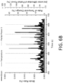
- FIG. 6 A is a graph demonstrating time-synchronization of information collected by the AOSS by using data obtained by the DIC (strain), AE (Partial Power 3 ) and an added infrared thermography system (surface temperature) in an exemplary application in the case of the compact tension coupon test shown in FIG. 2 B ;
- FIG. 6 B is an enlargement of a portion of the graph of FIG. 6 A marked by the broken line that shows the time synchronization of the three different datasets achieved by the AOSS;
- FIG. 7 is an exemplary application of integrating information (data fusion) obtained by the AOSS for damage diagnosis in the case of the compact tension coupon test shown in FIG. 2 B , with the Mahalanobis distance being defined as a parameter using information from both DIC and AE in the AOSS;
- FIG. 8 A is a graph highlighting the correlation between DIC (residual stiffness) and AE (cumulative energy) data with lifetime fractions of a laboratory coupon similar to the laboratory coupon shown in FIG. 2 A ;
- FIG. 8 B is another graph highlighting the correlation between DIC (energy density) and AE (cumulative energy) data with lifetime fractions of a laboratory coupon.
- exemplary is used herein to mean serving as an example, instance, or illustration. Any aspect or design described herein as “exemplary” is not necessarily to be construed as preferred or advantageous over other aspects or designs. Rather, use of the word exemplary is intended to present concepts in a concrete fashion.
- the term “or” is intended to mean an inclusive “or” rather than an exclusive “or”. That is, unless specified otherwise, or clear from context, “X employs A or B” is intended to mean any of the natural inclusive permutations. That is, if X employs A; X employs B; or X employs both A and B, then “X employs A or B” is satisfied under any of the foregoing instances.
- the articles “a” and “an” as used in this application and the appended claims should generally be construed to mean “one or more” unless specified otherwise or clear from context to be directed to a singular form.
- the present invention includes an optical and an acoustic method to adaptively obtain full field deformation measurements on a material's or structure's surface based on a signal formed by extracting information from volume-related measurements of naturally occurring acoustic emission.
- This invention referred to here as “Acousto-Optical Sensing System (AOSS)”, describes the communication between its constituents and basis of operation using the Digital Image Correlation (DIC) and Acoustic Emission (AE) methods.
- DIC Digital Image Correlation
- AE Acoustic Emission
- This approach can be used to time-synchronize full field deformation measurements with emission of acoustic stress waves occurring in the inspected volume of a material and/or structure by natural causes such as evolving damage due to the application of external loadings, such as, for example, mechanical, thermal, environmental, and other types of loadings.
- the present invention also provides a novel approach of integrating in real testing time the DIC with the AE method both at the hardware and at the post processing/analysis levels.
- the hardware integration between the two techniques is based on user-defined, multi-parametric criteria in the AE system that are used to form a digital output signal. Upon receiving this signal, the DIC cameras are automatically activated and triggered to acquire images based on a user-built script. Consequently, the unique advantage of this hardware integration is an adaptive recording and therefore also memory-storage effective NDE approach that can time-synchronize acoustic with optical information related to material and/or structural failure.
- a mechanical test stand 110 is used to apply mechanical load to a test specimen 112 , which simulates an object under load.
- object may be a bridge beam, a building column, an airframe, or other structural element that may be under load by its normal operational environment.
- the load may be a compressive load, a tensile load, a torsional load, a bending load, environmental load, fatigue load or any other load that may be experienced by structural elements.
- test stand 110 provides axial tensile/compressive loads to a test specimen 112 .
- test specimen 112 is shown in FIG. 2 A .
- Test specimen 112 is an aluminum alloy designed according to (ASTM) standards, although those skilled in the art will recognize that test specimen 112 can be other materials as well.
- Test specimen 112 a in FIG. 2 B is another example of the same material with a different specimen geometry based on American Society for Testing and Materials (“ASTM”) standards.
- Test specimen 113 shown in FIG. 2 C is a partially reinforced concrete masonry wall to demonstrate the applicability of the AOSS in several materials and at different length scales.
- An exemplary AE data acquisition system includes the four-channel DiSP system 114 developed by Physical Acoustics Corporation, schematically shown in FIG. 1 .
- AE system 114 is equipped with four piezoelectric transducers 115 - 118 and associated preamplifiers 119 - 122 . While a single transducer 115 may be used, additional transducers 116 - 118 may be used as receivers that passively receive acoustic stress waves propagating through test specimen 112 , 113 during testing. Further, while piezoelectric transducers are used, other sensors technologies, such as fiber bragg and MEMS sensors can be used. Such sensing technologies are referred to as “acoustic sensors” in the remainder of this text.
- the system 114 shown in FIG. 1 has analog inputs that allow load and displacement/strain recordings from the mechanical test stand 110 .
- the exemplary DIC data acquisition system 123 is a GOM ARAMIS 3D 5-megapixel camera system with analog inputs that allow load recording from the mechanical test stand 110 .
- the data acquisition of the DIC system 123 also supports input/output ports that can trigger the cameras to activate and record images based on an external trigger.
- Exemplary 5-megapixel cameras are Baumer TGX15 124 - 125 , shown in FIG. 3 A .
- the AE system 114 is electronically connected to the DIC system using BNC cables and an external parametric box, shown at 101 in FIG. 1 , so that information in the form of input/output signals between the AE system 114 and the DIC system 123 can be exchanged in real experimental time.
- the direct connection between the AE system 14 and the DIC system 123 enables the DIC system 123 to be automatically activated and triggered to acquire images based on a TTL signal generated by the AE system 114 .
- the AE system 114 is connected using BNC cables 102 to test stand 110 and to a load cell 105 using BNC cables 103 .
- the AE system 114 is also equipped to receive load/displacement or any other parametric input in real time through a parametric box.
- the DIC system 123 is connected to the load cell 105 by BNC cables 104 .
- a closed loop is formed between test stand 110 , DIC system 123 , and AE system 114 so that information (for example, load) recorded from one system can be passed to other systems (for example AE and DIC) and synchronized at both the time and loading stages.
- information for example, load
- other systems for example AE and DIC
- a contrasting speckle pattern For DIC measurements, a contrasting speckle pattern must be present on the surface of test specimens 112 - 113 .
- a random speckle pattern is applied on the surface of test specimens 112 - 113 for tracking deformation, and pretest images of test specimens 112 - 113 are taken to determine the sensitivity of system 123 for a particular field of view.
- the random speckle pattern is used to identify the relative displacement of test specimens 112 - 113 by correlating the acquired images to a known reference image under load.
- true stress calculated by using data recorded by the load cell of the test stand
- true strain calculated by using the DIC system
- AE data AE waveform amplitude distribution
- crack length monitoring computed by the DIC system
- the cumulative absolute energy computed by the AE system
- FIG. 5 A Additional exemplary correlations between DIC, AE and mechanical test data are shown in FIG. 5 A in case of cyclic loading of a structural component.
- the cumulative energy computed by the AE system is synchronized with load information and is used to trigger the cameras of the DIC system that record full field images of surface deformation (in this case strain) as shown in FIG. 5 .
- FIG. 5 A shows the specific AE feature (cumulative energy as a function of time and correlated with load recorded by the mechanical test machine and also read by the AOSS trends data. Note the two time instances denoted by the two vertical broken lines and labeled as “Crack Initiation” and “Critical Crack Growth”. Changes in the AE features at this time instances were used to trigger the DIC system and record full field surface strain information as shown in FIGS. 5 B and 5 C .
- FIG. 5 B shows representative images with full field surface strain distribution showing crack initiation, noted by the box “B” on the bottom left corner of the Figure, which corresponds to the first time instance marked in FIG. 5 A .
- FIG. 5 C shows similar surface strain distribution on the masonry wall that corresponds to the second time instance marked as “Critical Crack Growth” in FIG. 5 A .
- the lines marked “C” correspond to regions on the wall with more pronounced crack formation and grown in a staircase pattern.
- the measured strain by the DIC system after receiving feedback from the AE system is plotted against a calculated AE feature (partial power, which is an AE parameter that can be extracted from digital signal processing) as well as the surface temperature change of the specimen measured by an addition to the exemplary AOSS which in this case also comprises an infrared thermography camera (not shown).
- a calculated AE feature partial power, which is an AE parameter that can be extracted from digital signal processing
- the surface temperature change of the specimen measured by an addition to the exemplary AOSS which in this case also comprises an infrared thermography camera (not shown).
- a parameter based on what is known as Mahalanobis distance was calculated by using features recorded by both the AE and DIC system, after the DIC system was triggered by the AE system; this parameter is used to detect the extent of damage (in this case length of crack in an experiment similar to the experiment illustrated in in FIG. 2 B ).
- FIG. 8 an exemplary application of how the demonstrated AOSS is used to predict the life fraction of a material or structural component is presented by plotting parameters computed by using DIC data (residual stiffness in FIG. 8 A and energy density in FIG. 8 B ) with the cumulative energy computed based on AE data. Note that DIC data were recorded after triggering of the DIC system using an input signal based on changes of the AE data.
- the advantages of the inventive Acoustic-Optical Sensing system include seamless integration of AE with DIC, in that AE and DIC are now capable of communicating with each other without manual intervention. Consequently, this novel setup provides deformation measurements through the DIC system based on criteria defined in the AE system. Further, the novel system provides the capability to acquire DIC imagery only when identified by the operator as “critical” AE information is recorded, thereby enabling digital memory savings in the DIC system. This aspect could be particularly useful in long-term SHM applications.
- the novel AOSS provides the opportunity to integrate full field mechanical parameters such as in- and out-of-plane deformation measurements and material properties including Poisson's ratio with time, frequency and joint time-frequency AE features such as amplitude, peak frequency, partial powers, and other known parameters. This combination of information enables a cross-validated evaluation of material and/or structural integrity which increases the reliability of the measurements recorded by each of the two systems independently.
Abstract
An inventive approach is disclosed to integrate Digital Image Correlation (DIC) with the Acoustic Emission method that may be used for structural health monitoring and assessment of critical structural components in civil, mechanical, and aerospace industries. The inventive approach relies on passively recording acoustic emission across the specimen being tested and activating the DIC cameras automatically to measure deformation on the specimen's surface. The resulting acousto-optic system can be used to determine damage initiation, progressive damage development, identify critical regions and make lifetime predictions of the tested specimen.
Description
The present application claims priority from PCT application PCT/US2013/37252, filed on Apr. 18, 2013, which claims priority from U.S. Provisional Patent Application Ser. No. 61/635,282, which was filed on Apr. 18, 2012, and which are incorporated herein in their entireties.
The present invention relates to a nondestructive testing and evaluation (NDT & E) system.
Structural Health Monitoring (SHM) is vital in ensuring the structural integrity of critical components utilized in the aerospace, civil and mechanical industries. The development of SHM has a direct impact on public safety, primarily because it is beneficial in identifying early signs of critical failure and is related to reduced downtime and life extension of aging components and structures.
NDT & E systems are often a crucial part of SHM applications. Currently, no single monitoring technique has been capable of performing complete structural evaluation due to several inherent challenges including unpredictable environmental and loading conditions, limitations of the techniques themselves, lack of an adequately dense sensing network, etc.
Structural integrity monitoring systems based on the Digital Image Correlation (DIC) or the Acoustic Emission (AE) methods currently exist, however they are typically implemented independently and they are operated manually when used to assess material and structural integrity.
Consequently, it would be beneficial to provide an integrated approach in which multiple NDT & E techniques are used to develop an effective SHM system.
Briefly, the present invention provides a NDT & E method of determining the structural integrity of a specimen or structure as external load (e.g. mechanical, thermal, environmental, etc.) is applied. The method comprises the steps of: attaching at least one acoustic sensor to the specimen; applying a contrasting pattern on the surface of the specimen; calibrating a pair of stereoscopic cameras at the contrasting pattern; passively recording acoustic stress waves propagating in the specimen using an AE system electronically coupled to the at least one acoustic sensor; automatically triggering operation of the cameras by the AE system; measuring deformation in the specimen based on load-induced movement of the contrasting pattern in a DIC system, the DIC system being electronically coupled to the cameras; and correlating acoustic stress waves and strain data to determine the structural health of the specimen.
The present invention also provides a digital trigger signal (AE output) that is formed based on real time recorded and naturally occurring acoustic emission information, which is parametrized and used to extract features, based on which the signal is formed and subsequently passed into a DIC system. This trigger signal automatically activates the cameras of a DIC system for adaptive image acquisition depending only upon activity recorded nondestructively by the AE method due to changes in material and or structural integrity.
Additionally, the present invention provides time-synchronization (fusion) of data obtained by the acoustic and optical nondestructive methods for cross-validation and interpretation of information related to material and/or structural integrity.
Further, the present invention provides the control of a mechanical testing machine, in cases when such a machine is used in conjunction with the combined AE and DIC systems, through a digital signal (DIC output) defined in the DIC system based on full field deformation measurements that are further enabled as described above.
The accompanying drawings, which are incorporated herein and constitute part of this invention, illustrate the presently preferred embodiments of the invention, and, together with the general description given above and the detailed description given below, serve to explain the features of the invention. In the drawings:
In the drawings, like numerals indicate like elements throughout. Certain terminology is used herein for convenience only and is not to be taken as a limitation on the present invention. The terminology includes the words specifically mentioned, derivatives thereof and words of similar import. The embodiments illustrated below are not intended to be exhaustive or to limit the invention to the precise form disclosed. These embodiments are chosen and described to best explain the principle of the invention and its application and practical use and to enable others skilled in the art to best utilize the invention.
Reference herein to “one embodiment” or “an embodiment” means that a particular feature, structure, or characteristic described in connection with the embodiment can be included in at least one embodiment of the invention. The appearances of the phrase “in one embodiment” in various places in the specification are not necessarily all referring to the same embodiment, nor are separate or alternative embodiments necessarily mutually exclusive of other embodiments. The same applies to the term “implementation.”
As used in this application, the word “exemplary” is used herein to mean serving as an example, instance, or illustration. Any aspect or design described herein as “exemplary” is not necessarily to be construed as preferred or advantageous over other aspects or designs. Rather, use of the word exemplary is intended to present concepts in a concrete fashion.
Additionally, the term “or” is intended to mean an inclusive “or” rather than an exclusive “or”. That is, unless specified otherwise, or clear from context, “X employs A or B” is intended to mean any of the natural inclusive permutations. That is, if X employs A; X employs B; or X employs both A and B, then “X employs A or B” is satisfied under any of the foregoing instances. In addition, the articles “a” and “an” as used in this application and the appended claims should generally be construed to mean “one or more” unless specified otherwise or clear from context to be directed to a singular form.
The present invention includes an optical and an acoustic method to adaptively obtain full field deformation measurements on a material's or structure's surface based on a signal formed by extracting information from volume-related measurements of naturally occurring acoustic emission. This invention, referred to here as “Acousto-Optical Sensing System (AOSS)”, describes the communication between its constituents and basis of operation using the Digital Image Correlation (DIC) and Acoustic Emission (AE) methods. The inventive system and method features an approach to activate and trigger recordings in cameras related to DIC based on signals formed and exported by the AE method. This approach can be used to time-synchronize full field deformation measurements with emission of acoustic stress waves occurring in the inspected volume of a material and/or structure by natural causes such as evolving damage due to the application of external loadings, such as, for example, mechanical, thermal, environmental, and other types of loadings.
The present invention also provides a novel approach of integrating in real testing time the DIC with the AE method both at the hardware and at the post processing/analysis levels. The hardware integration between the two techniques is based on user-defined, multi-parametric criteria in the AE system that are used to form a digital output signal. Upon receiving this signal, the DIC cameras are automatically activated and triggered to acquire images based on a user-built script. Consequently, the unique advantage of this hardware integration is an adaptive recording and therefore also memory-storage effective NDE approach that can time-synchronize acoustic with optical information related to material and/or structural failure.
An exemplary AOSS system 100 according to the present invention is shown in FIG. 1 . A mechanical test stand 110 is used to apply mechanical load to a test specimen 112, which simulates an object under load. Such object may be a bridge beam, a building column, an airframe, or other structural element that may be under load by its normal operational environment. The load may be a compressive load, a tensile load, a torsional load, a bending load, environmental load, fatigue load or any other load that may be experienced by structural elements. In this particular embodiment, test stand 110 provides axial tensile/compressive loads to a test specimen 112.
An exemplary AE data acquisition system includes the four-channel DiSP system 114 developed by Physical Acoustics Corporation, schematically shown in FIG. 1 . AE system 114 is equipped with four piezoelectric transducers 115-118 and associated preamplifiers 119-122. While a single transducer 115 may be used, additional transducers 116-118 may be used as receivers that passively receive acoustic stress waves propagating through test specimen 112, 113 during testing. Further, while piezoelectric transducers are used, other sensors technologies, such as fiber bragg and MEMS sensors can be used. Such sensing technologies are referred to as “acoustic sensors” in the remainder of this text. The system 114 shown in FIG. 1 has analog inputs that allow load and displacement/strain recordings from the mechanical test stand 110.
The exemplary DIC data acquisition system 123 is a GOM ARAMIS 3D 5-megapixel camera system with analog inputs that allow load recording from the mechanical test stand 110. In addition, the data acquisition of the DIC system 123 also supports input/output ports that can trigger the cameras to activate and record images based on an external trigger. Exemplary 5-megapixel cameras are Baumer TGX15 124-125, shown in FIG. 3A .
The AE system 114 is electronically connected to the DIC system using BNC cables and an external parametric box, shown at 101 in FIG. 1 , so that information in the form of input/output signals between the AE system 114 and the DIC system 123 can be exchanged in real experimental time. An exemplary
The direct connection between the AE system 14 and the DIC system 123 enables the DIC system 123 to be automatically activated and triggered to acquire images based on a TTL signal generated by the AE system 114. Additionally, the AE system 114 is connected using BNC cables 102 to test stand 110 and to a load cell 105 using BNC cables 103. Thus, the AE system 114 is also equipped to receive load/displacement or any other parametric input in real time through a parametric box. Further, the DIC system 123 is connected to the load cell 105 by BNC cables 104. A closed loop is formed between test stand 110, DIC system 123, and AE system 114 so that information (for example, load) recorded from one system can be passed to other systems (for example AE and DIC) and synchronized at both the time and loading stages.
For DIC measurements, a contrasting speckle pattern must be present on the surface of test specimens 112-113. In this case, a random speckle pattern is applied on the surface of test specimens 112-113 for tracking deformation, and pretest images of test specimens 112-113 are taken to determine the sensitivity of system 123 for a particular field of view. The random speckle pattern is used to identify the relative displacement of test specimens 112-113 by correlating the acquired images to a known reference image under load.
In an alternative embodiment, such as, for example, determining strain in a bridge beam (not shown), if natural surface contrasts are readily present on the beam, such as, for example, dirt, paint chips, or any other random pattern, then the random speckle pattern does not necessarily need to be applied to the beam. In such a situation, a load is already present in the beam and the piezoelectric transducers 115-118 are attached to the beam after the load has been applied to the beam.
As an exemplary method, true stress (calculated by using data recorded by the load cell of the test stand) versus true strain (calculated by using the DIC system), while AE data (AE waveform amplitude distribution) has been synchronized and added to the true stress-true strain curve in FIG. 4A . As an additional exemplary method, crack length monitoring (computed by the DIC system) as a function of applied (by the test stand) load and the cumulative absolute energy (computed by the AE system) is shown in FIG. 4B . The AE system and the features extracted or computed by it were used in the examples shown to activate and record data by the DIC system.
Additional exemplary correlations between DIC, AE and mechanical test data are shown in FIG. 5A in case of cyclic loading of a structural component. The cumulative energy computed by the AE system is synchronized with load information and is used to trigger the cameras of the DIC system that record full field images of surface deformation (in this case strain) as shown in FIG. 5 .
In FIGS. 6A and 6B , the measured strain by the DIC system after receiving feedback from the AE system is plotted against a calculated AE feature (partial power, which is an AE parameter that can be extracted from digital signal processing) as well as the surface temperature change of the specimen measured by an addition to the exemplary AOSS which in this case also comprises an infrared thermography camera (not shown).
In FIG. 7 , a parameter based on what is known as Mahalanobis distance was calculated by using features recorded by both the AE and DIC system, after the DIC system was triggered by the AE system; this parameter is used to detect the extent of damage (in this case length of crack in an experiment similar to the experiment illustrated in in FIG. 2B ).
In FIG. 8 an exemplary application of how the demonstrated AOSS is used to predict the life fraction of a material or structural component is presented by plotting parameters computed by using DIC data (residual stiffness in FIG. 8A and energy density in FIG. 8B ) with the cumulative energy computed based on AE data. Note that DIC data were recorded after triggering of the DIC system using an input signal based on changes of the AE data.
The advantages of the inventive Acoustic-Optical Sensing system include seamless integration of AE with DIC, in that AE and DIC are now capable of communicating with each other without manual intervention. Consequently, this novel setup provides deformation measurements through the DIC system based on criteria defined in the AE system. Further, the novel system provides the capability to acquire DIC imagery only when identified by the operator as “critical” AE information is recorded, thereby enabling digital memory savings in the DIC system. This aspect could be particularly useful in long-term SHM applications.
Additionally, the novel AOSS provides the opportunity to integrate full field mechanical parameters such as in- and out-of-plane deformation measurements and material properties including Poisson's ratio with time, frequency and joint time-frequency AE features such as amplitude, peak frequency, partial powers, and other known parameters. This combination of information enables a cross-validated evaluation of material and/or structural integrity which increases the reliability of the measurements recorded by each of the two systems independently.
It will be appreciated by those skilled in the art that changes could be made to the embodiments described above without departing from the broad inventive concept thereof. It is understood, therefore, that this invention is not limited to the particular embodiments disclosed, but it is intended to cover modifications within the spirit and scope of the present invention as defined by the appended claims.
Claims (10)
1. A nondestructive method of determining the structural integrity of a specimen as a load is applied to the specimen, the method comprising the steps of:
attaching at least one acoustic emission sensor to the specimen;
applying a contrasting pattern on the surface of the specimen;
aiming a pair of stereoscopic cameras at the contrasting pattern;
passively recording acoustic stress waves propagating in the specimen in an Acoustic Emission (AE) system electronically coupled to the at least one acoustic emission sensor;
time synchronizing cumulative energy calculated from the AE data with information about the load;
triggering operation of the cameras by the AE system;
adaptively recording data generated by operation of the cameras;
measuring deformation in the specimen based on load-induced movement of the contrasting pattern in a Digital Image Correlation (DIC) system, the DIC system being electronically coupled to the cameras; and
correlating stress waves travelling through the specimen measured by the at least one acoustic emission sensor with strain data measured on a surface of the specimen to compute a Mahalanobis distance of the specimen.
2. The method according to claim 1 , further comprising, after calibrating the cameras at the contrasting pattern, applying a load to the specimen.
3. The method according to claim 2 , wherein the load applying step comprises attaching the specimen to a load applying test stand.
4. The method according to claim 3 , wherein the at least one acoustic emission sensor and the cameras are electrically connected to the test stand.
5. The method according to claim 4 , wherein a digital output is sent from the AE system to the DIC system.
6. The method according to claim 5 , further comprising triggering the DIC cameras based on an input signal received from the AE system.
7. The method according to claim 6 , wherein the correlating step comprises measuring deformation in the specimen synchronized with the applied load and acoustic activity.
8. The method according claim 7 , wherein the correlating step comprises computing a life fraction of the specimen by using synchronized DIC and AE data.
9. The method according to claim 1 , wherein the at least one acoustic sensor comprises a plurality of acoustic sensors.
10. A method of determining the structural integrity of a specimen as a load is applied to the specimen, the method comprising the steps of:
prior to applying the load:
attaching at least one acoustic emission sensor to the specimen;
determining a contrasting pattern on the surface of the specimen; and
aiming two cameras at the contrasting pattern;
determining strain in the specimen based on load-induced movement of the contrasting pattern;
passively recording acoustic stress waves propagating in the specimen; and
correlating stress waves travelling through the specimen with strain data measured on a surface of the specimen to determine structural health of the specimen and to compute a Mahalanobis distance for the specimen.
Priority Applications (1)
| Application Number | Priority Date | Filing Date | Title |
|---|---|---|---|
| US17/340,157 US11703482B2 (en) | 2012-04-18 | 2021-06-07 | Computing progressive failure in materials and structures by integration of digital image correlation with acoustic emission monitoring data |
Applications Claiming Priority (5)
| Application Number | Priority Date | Filing Date | Title |
|---|---|---|---|
| US201261635282P | 2012-04-18 | 2012-04-18 | |
| PCT/US2013/037252 WO2013158933A1 (en) | 2012-04-18 | 2013-04-18 | Integration of digital image correlation with acoustic emissions |
| US14/516,708 US10488368B2 (en) | 2012-04-18 | 2014-10-17 | Integration of digital image correlation with acoustic emission |
| US16/120,355 US20190017968A1 (en) | 2012-04-18 | 2018-09-03 | Integration of Digital Image Correlation with Acoustic Emission |
| US17/340,157 US11703482B2 (en) | 2012-04-18 | 2021-06-07 | Computing progressive failure in materials and structures by integration of digital image correlation with acoustic emission monitoring data |
Related Parent Applications (1)
| Application Number | Title | Priority Date | Filing Date |
|---|---|---|---|
| US16/120,355 Continuation US20190017968A1 (en) | 2012-04-18 | 2018-09-03 | Integration of Digital Image Correlation with Acoustic Emission |
Publications (2)
| Publication Number | Publication Date |
|---|---|
| US20210302381A1 US20210302381A1 (en) | 2021-09-30 |
| US11703482B2 true US11703482B2 (en) | 2023-07-18 |
Family
ID=49384082
Family Applications (3)
| Application Number | Title | Priority Date | Filing Date |
|---|---|---|---|
| US14/516,708 Active 2033-07-27 US10488368B2 (en) | 2012-04-18 | 2014-10-17 | Integration of digital image correlation with acoustic emission |
| US16/120,355 Abandoned US20190017968A1 (en) | 2012-04-18 | 2018-09-03 | Integration of Digital Image Correlation with Acoustic Emission |
| US17/340,157 Active 2033-11-12 US11703482B2 (en) | 2012-04-18 | 2021-06-07 | Computing progressive failure in materials and structures by integration of digital image correlation with acoustic emission monitoring data |
Family Applications Before (2)
| Application Number | Title | Priority Date | Filing Date |
|---|---|---|---|
| US14/516,708 Active 2033-07-27 US10488368B2 (en) | 2012-04-18 | 2014-10-17 | Integration of digital image correlation with acoustic emission |
| US16/120,355 Abandoned US20190017968A1 (en) | 2012-04-18 | 2018-09-03 | Integration of Digital Image Correlation with Acoustic Emission |
Country Status (2)
| Country | Link |
|---|---|
| US (3) | US10488368B2 (en) |
| WO (1) | WO2013158933A1 (en) |
Families Citing this family (28)
| Publication number | Priority date | Publication date | Assignee | Title |
|---|---|---|---|---|
| CN103592373A (en) * | 2013-11-21 | 2014-02-19 | 冶金自动化研究设计院 | Multivariate statics visual model of transient trigger signal |
| US10101263B1 (en) * | 2013-12-06 | 2018-10-16 | Us Synthetic Corporation | Methods for evaluating superabrasive elements |
| JP6567268B2 (en) * | 2014-11-18 | 2019-08-28 | 株式会社東芝 | Signal processing device, server device, detection system, and signal processing method |
| US11354881B2 (en) | 2015-07-27 | 2022-06-07 | United Launch Alliance, L.L.C. | System and method to enable the application of optical tracking techniques for generating dynamic quantities of interest with alias protection |
| US10605783B2 (en) * | 2015-08-20 | 2020-03-31 | United States Of America As Represented By The Administrator Of Nasa | System and method for progressive damage monitoring and failure event prediction in a composite structure |
| CN105527176B (en) * | 2016-02-03 | 2018-11-06 | 中国矿业大学 | Experimental rig for jointed rock mass failure mechanism in deep under impact load |
| CN105929027B (en) * | 2016-03-31 | 2018-07-13 | 辽宁工程技术大学 | A kind of measurement method that strain field acoustie emission event space-time is strong |
| CN109313110A (en) | 2016-05-13 | 2019-02-05 | 沙特基础工业全球技术公司 | Use the application assessment of digital image correlation technique |
| CN106152964B (en) * | 2016-07-19 | 2018-08-07 | 辽宁工程技术大学 | A kind of measuring method of plane planted agent's variability field based on speed linearity fitting |
| US10442548B2 (en) | 2017-08-25 | 2019-10-15 | Simmonds Precision Products, Inc. | Interactive analysis of structural health data |
| US11536701B2 (en) | 2017-08-25 | 2022-12-27 | Simmonds Precision Products, Inc. | Interactive transformational analysis of structural health monitoring data |
| CN107610112A (en) * | 2017-09-12 | 2018-01-19 | 武汉大学 | A kind of curved-surface building thing damnification recognition method based on digitlization modal coordinate |
| US11276159B1 (en) | 2018-05-15 | 2022-03-15 | United Launch Alliance, L.L.C. | System and method for rocket engine health monitoring using digital image correlation (DIC) |
| CN109060824A (en) * | 2018-08-10 | 2018-12-21 | 广东工业大学 | Strain-pulse based on DIC technology responds covariance damnification recognition method |
| CN109187222A (en) * | 2018-09-30 | 2019-01-11 | 中国石油大学(北京) | The test method and device of oil shale fracture |
| CN109632487A (en) * | 2019-01-14 | 2019-04-16 | 东北大学 | A kind of qualitative test method of interior rock internal strain field under load effect |
| CN110207606B (en) * | 2019-06-27 | 2021-04-20 | 航天神舟飞行器有限公司 | Out-of-plane strain measurement method based on digital image correlation |
| CN110320109B (en) * | 2019-07-02 | 2020-08-28 | 中国石油大学(北京) | Test method and device for monitoring fracturing process of high-temperature plate-shaped oil shale |
| CN110470444B (en) * | 2019-09-24 | 2020-12-01 | 苏交科集团股份有限公司 | DIC technology-based automatic bridge actual stress testing system |
| US11454595B2 (en) | 2019-12-06 | 2022-09-27 | Saudi Arabian Oil Company | Systems and methods for evaluating a structural health of composite components by correlating positions of displaced nanoparticles |
| TWI724897B (en) | 2020-05-14 | 2021-04-11 | 財團法人工業技術研究院 | Strain measurement method and strain measurement apparatus |
| CN111610099B (en) * | 2020-07-08 | 2022-08-02 | 郑州大学 | Rubber concrete fracture performance analysis method based on temperature and humidity changes |
| CN112630217A (en) * | 2020-11-23 | 2021-04-09 | 清华大学 | Concrete alkali aggregate testing method and system based on digital speckle technology |
| CN112556594A (en) * | 2020-11-25 | 2021-03-26 | 华中科技大学 | Strain field and temperature field coupling measurement method and system fusing infrared information |
| CN113030261B (en) * | 2021-03-04 | 2022-05-20 | 武汉科技大学 | Dynamic transient nondestructive testing method for high-temperature service performance of material |
| CN113740352B (en) * | 2021-09-08 | 2022-11-22 | 四川大学 | Method for integrally detecting blade cracks and residual stress of aero-engine |
| CN114813964B (en) * | 2022-04-24 | 2023-08-22 | 中国工程物理研究院化工材料研究所 | Method for deciding cracking damage of brittle material structural member by adopting time domain information |
| CN115629130B (en) * | 2022-12-21 | 2023-04-28 | 国网天津市电力公司电力科学研究院 | Imaging method and system for residual stress of basin-type insulator and test block preparation method |
Citations (8)
| Publication number | Priority date | Publication date | Assignee | Title |
|---|---|---|---|---|
| US4480480A (en) * | 1981-05-18 | 1984-11-06 | Scott Science & Technology, Inc. | System for assessing the integrity of structural systems |
| US4781455A (en) | 1985-05-08 | 1988-11-01 | Carl-Zeiss-Stiftung | Method for measuring optical strain and apparatus therefor |
| US5757473A (en) | 1996-11-13 | 1998-05-26 | Noranda, Inc. | Optical strain sensor for the measurement of microdeformations of surfaces |
| US20050207487A1 (en) * | 2000-06-14 | 2005-09-22 | Monroe David A | Digital security multimedia sensor |
| US20070209447A1 (en) | 2006-03-10 | 2007-09-13 | Northrop Grumman Corporation | In-situ large area optical strain measurement using an encoded dot pattern |
| US20080105055A1 (en) * | 2006-11-03 | 2008-05-08 | General Electric Company | Systems and method for locating failure events in samples under load |
| US20090015274A1 (en) * | 2005-03-04 | 2009-01-15 | Omniprobe, Inc. | Method for automated stress testing of flip-chip packages |
| US20110040496A1 (en) | 2009-08-13 | 2011-02-17 | Banerjee Sourav | Method and apparatus for estimating damage in a structure |
Family Cites Families (5)
| Publication number | Priority date | Publication date | Assignee | Title |
|---|---|---|---|---|
| US84903A (en) * | 1868-12-15 | Improvement in cloth-mbasttring apparatus | ||
| KR20030016029A (en) * | 2001-08-20 | 2003-02-26 | 김재열 | Welding flaw detecting method of Spiral Welding Pipe |
| KR100581307B1 (en) * | 2001-12-17 | 2006-05-22 | 다이킨 고교 가부시키가이샤 | Elastomer Formed Product |
| US20090116533A1 (en) * | 2007-11-02 | 2009-05-07 | General Electric Company | Method and apparatus for testing and evaluating machine components under simulated in-situ thermal operating conditions |
| US8402811B2 (en) * | 2010-06-26 | 2013-03-26 | Yining Nie | Cyclic impact-sliding fatigue wear testing instrument |
-
2013
- 2013-04-18 WO PCT/US2013/037252 patent/WO2013158933A1/en active Application Filing
-
2014
- 2014-10-17 US US14/516,708 patent/US10488368B2/en active Active
-
2018
- 2018-09-03 US US16/120,355 patent/US20190017968A1/en not_active Abandoned
-
2021
- 2021-06-07 US US17/340,157 patent/US11703482B2/en active Active
Patent Citations (9)
| Publication number | Priority date | Publication date | Assignee | Title |
|---|---|---|---|---|
| US4480480A (en) * | 1981-05-18 | 1984-11-06 | Scott Science & Technology, Inc. | System for assessing the integrity of structural systems |
| US4781455A (en) | 1985-05-08 | 1988-11-01 | Carl-Zeiss-Stiftung | Method for measuring optical strain and apparatus therefor |
| US5757473A (en) | 1996-11-13 | 1998-05-26 | Noranda, Inc. | Optical strain sensor for the measurement of microdeformations of surfaces |
| US20050207487A1 (en) * | 2000-06-14 | 2005-09-22 | Monroe David A | Digital security multimedia sensor |
| US20090015274A1 (en) * | 2005-03-04 | 2009-01-15 | Omniprobe, Inc. | Method for automated stress testing of flip-chip packages |
| US20070209447A1 (en) | 2006-03-10 | 2007-09-13 | Northrop Grumman Corporation | In-situ large area optical strain measurement using an encoded dot pattern |
| US7377181B2 (en) | 2006-03-10 | 2008-05-27 | Northrop Grumman Corporation | In-situ large area optical strain measurement using an encoded dot pattern |
| US20080105055A1 (en) * | 2006-11-03 | 2008-05-08 | General Electric Company | Systems and method for locating failure events in samples under load |
| US20110040496A1 (en) | 2009-08-13 | 2011-02-17 | Banerjee Sourav | Method and apparatus for estimating damage in a structure |
Non-Patent Citations (8)
| Title |
|---|
| (Multiscale monitoring of interface failure of brittle coating/ductile substrate systems: A non-destructive evaluation method combined digital image correlation with acoustic emission, Journal of Applied Physics, Oct. 18, 2011, vol. 110, No. 8, pp. 084903/1-5), hereinafter "MAO") (Year: 2011). * |
| International Preliminary Report on Patentability, PCT/US2013/037252, dated Oct. 21, 2014. 9 pages. |
| International Search Report and Written Opinion, PCT/US2012/037252, dated Jul. 23, 2013. 3 pages. |
| Jiang, H. et al. "Characterization of microplasticity in TiAl-based alloys:", Science Direct 2009. pp 1357-1366. |
| Louche, H. et al. Kinematic Fields and Acoustic Emission Observations Associated with the Portevin Le Chatelier Effect on an Al—Mg Alloy Experimental Mechanics, 2008. 48:741-751. |
| Mao, W.G. et al., "Multiscale monitoring of interface failure of brittle coating/ductile substrate systems: A non-destructive evaluation method combined digital image correlation with acoustic emission", Journal of Applied Physics, vol. 10, Issue 8. 20011. 8 pages. |
| Pullin, R. et al. "Validation of Acoustic Emission (AE) Crack Detection in Aerospace Grade Steel Using Digital Image Correlation". Applied Mechanics and Materials 2010. p. 221-226. |
| Sun, X. et al. Predicting failure modes and ductility of dual phase steels using plastic strain localization. International Journal of Plasticity, 2009, pp. 1888-1909. |
Also Published As
| Publication number | Publication date |
|---|---|
| US20190017968A1 (en) | 2019-01-17 |
| US20210302381A1 (en) | 2021-09-30 |
| US10488368B2 (en) | 2019-11-26 |
| WO2013158933A1 (en) | 2013-10-24 |
| US20150035950A1 (en) | 2015-02-05 |
Similar Documents
| Publication | Publication Date | Title |
|---|---|---|
| US11703482B2 (en) | Computing progressive failure in materials and structures by integration of digital image correlation with acoustic emission monitoring data | |
| Hassani et al. | A systematic review of advanced sensor technologies for non-destructive testing and structural health monitoring | |
| Kudela et al. | Identification of cracks in thin-walled structures by means of wavenumber filtering | |
| Lacidogna et al. | Damage monitoring of three-point bending concrete specimens by acoustic emission and resonant frequency analysis | |
| Song et al. | Electromechanical impedance measurement from large structures using a dual piezoelectric transducer | |
| Saravanan et al. | Damage detection in structural element through propagating waves using radially weighted and factored RMS | |
| Yang et al. | Influence of crack opening and incident wave angle on second harmonic generation of Lamb waves | |
| Dong et al. | Non-destructive testing and evaluation (NDT/NDE) of civil structures rehabilitated using fiber reinforced polymer (FRP) composites | |
| Vanniamparambil et al. | Novel optico‐acoustic nondestructive testing for wire break detection in cables | |
| Loupos et al. | Structural health monitoring fiber optic sensors | |
| Ling et al. | Detecting mechanical impedance of structures using the sensing capability of a piezoceramic inertial actuator | |
| Wu et al. | Crack diagnosis method for a cantilevered beam structure based on modal parameters | |
| Zhou et al. | A feasibility study on monitoring of weld fatigue crack growth based on coda wave interferometry (CWI) | |
| Dos Santos et al. | An overview of experimental strain-based modal analysis methods | |
| CN112285651B (en) | Method and system for identifying impact source position of composite material based on feature extraction matrix similarity | |
| JP2012229982A (en) | Method and apparatus for health monitoring of concrete structure | |
| Bui et al. | Assessing local-scale damage in reinforced concrete frame structures using dynamic measurements | |
| Scheyer et al. | Impedance-based structural health monitoring of additive manufactured structures with embedded piezoelectric wafers | |
| Annamdas et al. | Fatigue Monitoring of double surface defects using PZT based Electromechanical Impedance and Digital image correlation methods | |
| Parida et al. | Comparative assessment of a multitudinal piezo arrangement for non-destructive evaluation of construction steel: An experimental study | |
| Tonelli et al. | Effectiveness of acoustic emission monitoring for in-service prestressed concrete bridges | |
| Sentosa et al. | Assessing Damage to Beam–Column Connections in Reinforced Concrete Structures from Vibrational Measurement Results | |
| Wang et al. | Relationship between local damage and structural dynamic behavior | |
| Khan et al. | Integrated health monitoring system for damage detection in civil structural components | |
| Khan et al. | Acoustics and temperature based NDT for damage assessment of concrete masonry system subjected to cyclic loading |
Legal Events
| Date | Code | Title | Description |
|---|---|---|---|
| FEPP | Fee payment procedure |
Free format text: ENTITY STATUS SET TO UNDISCOUNTED (ORIGINAL EVENT CODE: BIG.); ENTITY STATUS OF PATENT OWNER: SMALL ENTITY |
|
| FEPP | Fee payment procedure |
Free format text: ENTITY STATUS SET TO SMALL (ORIGINAL EVENT CODE: SMAL); ENTITY STATUS OF PATENT OWNER: SMALL ENTITY |
|
| STPP | Information on status: patent application and granting procedure in general |
Free format text: DOCKETED NEW CASE - READY FOR EXAMINATION |
|
| STCF | Information on status: patent grant |
Free format text: PATENTED CASE |
|
| STCF | Information on status: patent grant |
Free format text: PATENTED CASE |