US11686360B2 - Lock nut - Google Patents

Lock nut Download PDF

Info

Publication number
US11686360B2
US11686360B2 US16/982,921 US201916982921A US11686360B2 US 11686360 B2 US11686360 B2 US 11686360B2 US 201916982921 A US201916982921 A US 201916982921A US 11686360 B2 US11686360 B2 US 11686360B2
Authority
US
United States
Prior art keywords
nut
blocking
faces
axis
face
Prior art date
Legal status (The legal status is an assumption and is not a legal conclusion. Google has not performed a legal analysis and makes no representation as to the accuracy of the status listed.)
Active, expires
Application number
US16/982,921
Other versions
US20210010553A1 (en
Inventor
Rosa Pinto
Jèrôme BERTRAND
Fabrice Umbdenstock
Philippe Bourlon
Current Assignee (The listed assignees may be inaccurate. Google has not performed a legal analysis and makes no representation or warranty as to the accuracy of the list.)
Hitachi Astemo France SAS
Original Assignee
Foundation Brakes France SAS
Priority date (The priority date is an assumption and is not a legal conclusion. Google has not performed a legal analysis and makes no representation as to the accuracy of the date listed.)
Filing date
Publication date
Application filed by Foundation Brakes France SAS filed Critical Foundation Brakes France SAS
Assigned to FOUNDATION BRAKES FRANCE SAS reassignment FOUNDATION BRAKES FRANCE SAS ASSIGNMENT OF ASSIGNORS INTEREST (SEE DOCUMENT FOR DETAILS). Assignors: UMBDENSTOCK, FABRICE, BERTRAND, JÈRÔME, BOURLON, PHILIPPE, PINTO, ROSA
Publication of US20210010553A1 publication Critical patent/US20210010553A1/en
Application granted granted Critical
Publication of US11686360B2 publication Critical patent/US11686360B2/en
Active legal-status Critical Current
Adjusted expiration legal-status Critical

Links

Images

Classifications

    • FMECHANICAL ENGINEERING; LIGHTING; HEATING; WEAPONS; BLASTING
    • F16ENGINEERING ELEMENTS AND UNITS; GENERAL MEASURES FOR PRODUCING AND MAINTAINING EFFECTIVE FUNCTIONING OF MACHINES OR INSTALLATIONS; THERMAL INSULATION IN GENERAL
    • F16DCOUPLINGS FOR TRANSMITTING ROTATION; CLUTCHES; BRAKES
    • F16D65/00Parts or details
    • F16D65/14Actuating mechanisms for brakes; Means for initiating operation at a predetermined position
    • F16D65/16Actuating mechanisms for brakes; Means for initiating operation at a predetermined position arranged in or on the brake
    • F16D65/18Actuating mechanisms for brakes; Means for initiating operation at a predetermined position arranged in or on the brake adapted for drawing members together, e.g. for disc brakes
    • BPERFORMING OPERATIONS; TRANSPORTING
    • B60VEHICLES IN GENERAL
    • B60TVEHICLE BRAKE CONTROL SYSTEMS OR PARTS THEREOF; BRAKE CONTROL SYSTEMS OR PARTS THEREOF, IN GENERAL; ARRANGEMENT OF BRAKING ELEMENTS ON VEHICLES IN GENERAL; PORTABLE DEVICES FOR PREVENTING UNWANTED MOVEMENT OF VEHICLES; VEHICLE MODIFICATIONS TO FACILITATE COOLING OF BRAKES
    • B60T13/00Transmitting braking action from initiating means to ultimate brake actuator with power assistance or drive; Brake systems incorporating such transmitting means, e.g. air-pressure brake systems
    • B60T13/74Transmitting braking action from initiating means to ultimate brake actuator with power assistance or drive; Brake systems incorporating such transmitting means, e.g. air-pressure brake systems with electrical assistance or drive
    • B60T13/741Transmitting braking action from initiating means to ultimate brake actuator with power assistance or drive; Brake systems incorporating such transmitting means, e.g. air-pressure brake systems with electrical assistance or drive acting on an ultimate actuator
    • FMECHANICAL ENGINEERING; LIGHTING; HEATING; WEAPONS; BLASTING
    • F16ENGINEERING ELEMENTS AND UNITS; GENERAL MEASURES FOR PRODUCING AND MAINTAINING EFFECTIVE FUNCTIONING OF MACHINES OR INSTALLATIONS; THERMAL INSULATION IN GENERAL
    • F16BDEVICES FOR FASTENING OR SECURING CONSTRUCTIONAL ELEMENTS OR MACHINE PARTS TOGETHER, e.g. NAILS, BOLTS, CIRCLIPS, CLAMPS, CLIPS OR WEDGES; JOINTS OR JOINTING
    • F16B33/00Features common to bolt and nut
    • F16B33/002Means for preventing rotation of screw-threaded elements
    • FMECHANICAL ENGINEERING; LIGHTING; HEATING; WEAPONS; BLASTING
    • F16ENGINEERING ELEMENTS AND UNITS; GENERAL MEASURES FOR PRODUCING AND MAINTAINING EFFECTIVE FUNCTIONING OF MACHINES OR INSTALLATIONS; THERMAL INSULATION IN GENERAL
    • F16DCOUPLINGS FOR TRANSMITTING ROTATION; CLUTCHES; BRAKES
    • F16D55/00Brakes with substantially-radial braking surfaces pressed together in axial direction, e.g. disc brakes
    • F16D55/02Brakes with substantially-radial braking surfaces pressed together in axial direction, e.g. disc brakes with axially-movable discs or pads pressed against axially-located rotating members
    • F16D55/22Brakes with substantially-radial braking surfaces pressed together in axial direction, e.g. disc brakes with axially-movable discs or pads pressed against axially-located rotating members by clamping an axially-located rotating disc between movable braking members, e.g. movable brake discs or brake pads
    • F16D55/224Brakes with substantially-radial braking surfaces pressed together in axial direction, e.g. disc brakes with axially-movable discs or pads pressed against axially-located rotating members by clamping an axially-located rotating disc between movable braking members, e.g. movable brake discs or brake pads with a common actuating member for the braking members
    • F16D55/225Brakes with substantially-radial braking surfaces pressed together in axial direction, e.g. disc brakes with axially-movable discs or pads pressed against axially-located rotating members by clamping an axially-located rotating disc between movable braking members, e.g. movable brake discs or brake pads with a common actuating member for the braking members the braking members being brake pads
    • F16D55/226Brakes with substantially-radial braking surfaces pressed together in axial direction, e.g. disc brakes with axially-movable discs or pads pressed against axially-located rotating members by clamping an axially-located rotating disc between movable braking members, e.g. movable brake discs or brake pads with a common actuating member for the braking members the braking members being brake pads in which the common actuating member is moved axially, e.g. floating caliper disc brakes
    • FMECHANICAL ENGINEERING; LIGHTING; HEATING; WEAPONS; BLASTING
    • F16ENGINEERING ELEMENTS AND UNITS; GENERAL MEASURES FOR PRODUCING AND MAINTAINING EFFECTIVE FUNCTIONING OF MACHINES OR INSTALLATIONS; THERMAL INSULATION IN GENERAL
    • F16DCOUPLINGS FOR TRANSMITTING ROTATION; CLUTCHES; BRAKES
    • F16D55/00Brakes with substantially-radial braking surfaces pressed together in axial direction, e.g. disc brakes
    • F16D2055/0004Parts or details of disc brakes
    • F16D2055/0016Brake calipers
    • FMECHANICAL ENGINEERING; LIGHTING; HEATING; WEAPONS; BLASTING
    • F16ENGINEERING ELEMENTS AND UNITS; GENERAL MEASURES FOR PRODUCING AND MAINTAINING EFFECTIVE FUNCTIONING OF MACHINES OR INSTALLATIONS; THERMAL INSULATION IN GENERAL
    • F16DCOUPLINGS FOR TRANSMITTING ROTATION; CLUTCHES; BRAKES
    • F16D2125/00Components of actuators
    • F16D2125/02Fluid-pressure mechanisms
    • F16D2125/06Pistons
    • FMECHANICAL ENGINEERING; LIGHTING; HEATING; WEAPONS; BLASTING
    • F16ENGINEERING ELEMENTS AND UNITS; GENERAL MEASURES FOR PRODUCING AND MAINTAINING EFFECTIVE FUNCTIONING OF MACHINES OR INSTALLATIONS; THERMAL INSULATION IN GENERAL
    • F16DCOUPLINGS FOR TRANSMITTING ROTATION; CLUTCHES; BRAKES
    • F16D2125/00Components of actuators
    • F16D2125/18Mechanical mechanisms
    • F16D2125/20Mechanical mechanisms converting rotation to linear movement or vice versa
    • F16D2125/34Mechanical mechanisms converting rotation to linear movement or vice versa acting in the direction of the axis of rotation
    • F16D2125/40Screw-and-nut
    • FMECHANICAL ENGINEERING; LIGHTING; HEATING; WEAPONS; BLASTING
    • F16ENGINEERING ELEMENTS AND UNITS; GENERAL MEASURES FOR PRODUCING AND MAINTAINING EFFECTIVE FUNCTIONING OF MACHINES OR INSTALLATIONS; THERMAL INSULATION IN GENERAL
    • F16DCOUPLINGS FOR TRANSMITTING ROTATION; CLUTCHES; BRAKES
    • F16D65/00Parts or details
    • F16D65/38Slack adjusters
    • F16D65/40Slack adjusters mechanical
    • F16D65/52Slack adjusters mechanical self-acting in one direction for adjusting excessive play
    • F16D65/56Slack adjusters mechanical self-acting in one direction for adjusting excessive play with screw-thread and nut
    • F16D65/567Slack adjusters mechanical self-acting in one direction for adjusting excessive play with screw-thread and nut for mounting on a disc brake

Definitions

  • the invention relates to nuts, for example brake caliper nuts intended to be fitted on braking systems.
  • a nut is an elementary component of a screw/nut system intended for the assembly of parts or the conversion of movement. It can be used to convert a rotational movement into a linear movement by forming a screw-nut system.
  • a nut of a vehicle wheel brake caliper converts the rotational movement of a screw into a linear movement, transmitted to a piston which pushes a brake pad.
  • the nut is therefore often housed inside the piston and must be connected thereto.
  • a nut already provided with means for blocking the rotation along the longitudinal axis of the nut in the form of a collar has already been proposed.
  • collars increase the piston volume.
  • the screw and the piston also often need to be modified.
  • the blocking face or at least one of the blocking faces being concave.
  • the space between the blocking means and the transmission means is therefore eliminated.
  • the nut is therefore thinner, which saves space and material.
  • the transmission face or at least one of the transmission faces comprises a spherical part.
  • At least one groove could cross the blocking face, or at least one of the blocking faces, and the transmission face, or at least one of the transmission faces.
  • Such a groove allows the brake fluid to flow between the piston and the nut.
  • the groove is curved along its length.
  • the groove opens out onto a longitudinal orifice of the nut.
  • the groove could also form a bearing surface perpendicular to the axis.
  • the bearing surface has at least one curved edge.
  • the nut could comprise several grooves, preferably identical to each other.
  • Another longitudinal end of the nut could have at least one other blocking face forming at least one other means for blocking the rotation of the nut along the longitudinal axis.
  • the forces blocking the rotation can therefore be distributed on the piston along the body of the nut.
  • the nut could be 20 to 50 mm long, preferably 30 to 40 mm long, more preferably 33 to 37 mm long, and even more preferably 35.5 to 36.1 mm long.
  • the nut could have an outer diameter of 15 to 35 mm, preferably 20 to 30 mm, more preferably 22 to 28 mm, and even more preferably 25 to 27 mm.
  • One side of an outer square of the nut could be 12 to 32 mm long, preferably 20 to 25 mm long, more preferably 22 to 24 mm long, and even more preferably 22.9 to 23.2 mm long.
  • the nut could have an inner diameter of 9 to 23 mm, preferably 12 to 18 mm, more preferably 15 to 17 mm, and even more preferably 16 to 16.5 mm.
  • a brake caliper comprising a nut according to the invention is also provided.
  • the brake caliper comprises a piston and a screw.
  • a braking device comprising a brake caliper according to the invention is also provided.
  • FIG. 1 is a perspective view of a nut according to the invention
  • FIG. 2 is a front view of the nut
  • FIG. 3 is another perspective view of the nut
  • FIG. 4 is a cross-sectional view of the nut, a screw and a piston according to the invention
  • FIG. 5 is a transverse view of a piston according to the invention.
  • FIG. 6 a is a transverse view of a brake caliper according to the invention.
  • FIG. 6 b is a diagram of the brake caliper comprising a nut, a screw and a piston according to the invention
  • FIG. 6 c is a diagram of a braking device according to the invention comprising the brake caliper,
  • FIG. 7 is a cross-sectional view of the piston
  • FIG. 8 is a transverse view of the piston along the plane VII-VII of FIG. 7 .
  • FIG. 9 is a front view of the nut.
  • the nut 1 comprises two parts: a body C on most of its length and an end head T.
  • the body has an external face having the shape of a straight circular cylinder of longitudinal axis 10 .
  • the nut is provided with an internal duct 8 opening out at each end 1 a and 1 b . It is therefore hollow.
  • the duct also has the shape of a straight circular cylinder of longitudinal axis 10 .
  • the end head T comprises several lateral faces 1 a 1 and several extremal faces 1 a 2 .
  • the lateral faces 1 a 1 form an octagon around the axis 10 . They can be flat, concave or convex. In this case, half of the faces 1 a 1 are flat and the other half are concave according to an alternate arrangement between the flat faces and the concave faces.
  • the extremal faces 1 a 2 form a pyramid with spherical faces of truncated octagonal base of height equal to the longitudinal axis 10 .
  • the extremal faces are partially spherical since they are part of a spherical cap.
  • a spherical cap is in fact a spherical surface formed by the intersection of a sphere and a plane.
  • the spherical cap forming the extremal faces 1 a 2 is formed by the intersection of a sphere whose centre belongs to the axis 10 and the plane containing the edges 12 .
  • the extremal faces 1 a 2 are divided into two groups: a first group 1 a 21 and a second group 1 a 22 .
  • the set of extremal faces 1 a 2 is partially spherical, however the extremal faces 1 a 2 may be concave or convex.
  • the faces 1 a 21 of the first group are concave and the faces 1 a 22 of the second group are convex.
  • half of the extremal faces are convex and the other half are concave according to an alternate arrangement between the convex faces and the concave faces.
  • the faces 1 a 22 are hollow unlike the faces 1 a 21 which are in relief.
  • the lateral and extremal faces have a common edge 12 .
  • the extremal 1 a 2 and lateral 1 a 1 faces are adjacent or contiguous.
  • the flat lateral faces have an edge in common with the convex extremal faces while the concave lateral faces have an edge in common with the concave lateral faces.
  • the end head T is provided with several grooves 6 .
  • the grooves 6 open out onto the orifice forming the end of the duct 8 and each form a bearing surface 14 perpendicular to the axis 10 .
  • the grooves 6 are directed longitudinally along a first radius of longitudinal curvature.
  • a radius of curvature of a curve is the radius of the curve osculating circle, also called the circle of curvature. This means that the radius of curvature is the radius of a circle following the curve as closely as possible.
  • the radius of longitudinal curvature of the groove 6 has the same centre as the radius of curvature of the spherical cap. In addition, this radius is contained in the axis 10 .
  • the circle of curvature of the spherical cap and that of the longitudinal curvature of the groove are homothetic: one is the image of the other according to a homothety having a centre belonging to the axis 10 .
  • the grooves 6 are also directed longitudinally along a second radius of lateral curvature.
  • the number of grooves 6 is arbitrary.
  • the end head T of the nut comprises four grooves, all identical to each other and arranged in a cross pattern as shown on FIG. 2 .
  • the radii of longitudinal curvature and the radii of lateral curvature are chosen depending on the circumstances.
  • the grooves 6 may each have identical radii of longitudinal curvature and different radii of lateral curvature, or vice versa. All the radii of curvature may also be identical from one groove to another, whether for the longitudinal curvatures or the lateral curvatures of the grooves 6 .
  • the radius of lateral or longitudinal curvature of a groove 6 may also vary along its length.
  • the grooves 6 are located on the convex faces 1 a 22 .
  • the faces 1 a 22 comprise the grooves 6
  • the grooves could be arranged on the concave faces 1 a 21 .
  • the grooves can be arranged according to other patterns: for example, they may be arranged according to the vertices of a regular polygon.
  • the curve defined by the points of the groove 6 having the smallest radial radius with respect to the axis 10 is a straight line according to this embodiment. This curve defines the path of the groove. Its geometry is generally arbitrary.
  • the other end 1 b of the nut 1 comprises a notch 18 in the body C of the nut.
  • the notch has a main face 1 b extending in a plane radial to the axis 10 .
  • the nut comprises a thread on the internal face 20 of the duct 8 .
  • the nut is intended to receive a screw 3 in the duct 8 .
  • the nut 1 is intended to be inserted in a piston 2 .
  • the piston 2 is provided with a longitudinal internal duct 22 and, at one end, longitudinal 22 a and extremal 22 b internal faces having a common edge 26 .
  • the piston duct 22 is cylindrical with a circular cross-section.
  • the orifice has a frustoconical shape at the closed end 28 of the piston, located on the right on FIGS. 4 and 5 .
  • the edge of the piston forming the entry of the orifice 22 is provided with an internal chamfer 32 at the other end 30 .
  • the screw 3 comprises an external thread adapted to cooperate with the internal thread of the nut 1 . It comprises a frustoconical screw head of which an angle at the top of a head generation cone is equal to the angle of inclination of the internal chamfer of the edge of the piston.
  • the screw 3 , the nut 1 and the piston 2 are arranged so that the common edge 12 of the lateral 1 a 1 and extremal 1 a 2 lateral faces is opposite the common edge 26 of the faces 22 a and 22 b of the piston.
  • the extremal faces 1 a 2 of the nut 1 provide a sphere/cone support between the nut 1 and the piston 2 .
  • the internal chamfer 32 of the edge of the piston is opposite the screw head 2 since the angles of inclination of the chamfer and of the truncated cone of the screw head are equal.
  • a brake caliper 16 shown on FIG. 6 a receives the screw 3 , the nut 1 and the piston 2 in the same configuration as on FIG. 4 .
  • a braking device 4 shown on FIG. 6 c comprises the brake caliper 16 .
  • the common edges 34 of the lateral faces 1 a 1 prevent the rotation of the nut 1 about the axis 10 relative to the piston 2 .
  • the lateral faces form a means of blocking the rotation of the nut 1 about the axis 10 .
  • the lateral faces 1 a 1 are therefore blocking faces. This blocking connects the piston 2 and the nut 1 together.
  • the rotation of the screw 3 relative to the caliper moves the nut 1 due to the shape complementarity between the external thread of the screw 3 and the internal thread of the nut 1 .
  • the nut 1 Since the nut 1 is connected to the piston 2 , its translation causes the translation of the piston 2 by means of the extremal faces 1 a 2 .
  • the extremal faces 1 a 2 therefore form means for transmitting a linear force along the axis 10 .
  • This force transmission allows the transmission of a linear movement along the axis 10 : the linear movement of the nut 1 along the axis 10 causes the linear movement of the piston 2 along the axis 10 .
  • the grooves 6 form passages. They therefore favor the flow of brake fluid inside the piston.
  • an outer diameter of the square of the nut is 26.05 mm instead of 29.65 mm.
  • a length of an outer square 36 , shown on FIG. 9 , of the nut is 23.05 mm (variation of 0.15 mm) instead of 26.65 mm (variation of 0.15 mm).
  • the outer square is defined as being the square formed by the intersection, in a plane orthogonal to the axis 10 , of straight lines tangential to the flat faces 1 a 1 , as shown on FIG. 9 .
  • Such a nut therefore adapts to pistons of smaller dimensions.
  • a diameter of the bearing area between the means for blocking the rotation of the nut 1 in this case the lateral faces 1 a 1 , and the piston 2 is 26 mm instead of 28 mm.
  • the inner diameter of the piston square is 28.5 mm (possible variation of 0.2 mm) instead of 32.1 mm (same variation).
  • the diameter of the nut/piston bearing cone is 16.2 mm instead of 19.8 mm.
  • the diameter of the nut sphere formed by the extremal faces 1 a 2 is 16.2 mm instead of 19.8 mm.
  • Such a nut can be used with a smaller screw and piston without having to modify their geometries.
  • the nut is easier to machine. Since there is no collar, the number of manufacturing steps is reduced. In addition, the bearing areas 14 formed by the grooves make the nut easier to machine since they cooperate more easily with machining claws. Lastly, they allow manufacture using a stamping method.

Landscapes

  • Engineering & Computer Science (AREA)
  • General Engineering & Computer Science (AREA)
  • Mechanical Engineering (AREA)
  • Transportation (AREA)
  • Braking Arrangements (AREA)
  • Transmission Devices (AREA)
  • Braking Systems And Boosters (AREA)

Abstract

A longitudinal end of the nut has:
    • at least one blocking face forming a means for blocking a rotation of the nut along a longitudinal axis of the nut, and
    • at least one transmission face forming a means for transmitting a force directed along the axis.
The blocking face or at least one of the blocking faces and the transmission face or at least one of the transmission faces have at least one common edge, and the blocking face or at least one of the blocking faces is concave.

Description

CROSS-REFERENCE TO RELATED APPLICATIONS
This application claims priority under 35 U.S.C. § 371 to the International Application No. PCT/EP2019/057799, filed Mar. 27, 2019, and to the French Application No. 1852707, filed Mar. 28, 2018, the contents of which are hereby incorporated by reference.
FIELD OF THE INVENTION
The invention relates to nuts, for example brake caliper nuts intended to be fitted on braking systems.
BACKGROUND OF THE INVENTION
A nut is an elementary component of a screw/nut system intended for the assembly of parts or the conversion of movement. It can be used to convert a rotational movement into a linear movement by forming a screw-nut system. For example, a nut of a vehicle wheel brake caliper converts the rotational movement of a screw into a linear movement, transmitted to a piston which pushes a brake pad. The nut is therefore often housed inside the piston and must be connected thereto.
A nut already provided with means for blocking the rotation along the longitudinal axis of the nut in the form of a collar has already been proposed. However, such collars increase the piston volume. In addition, if the nut geometry is modified, the screw and the piston also often need to be modified.
OBJECT AND SUMMARY OF THE INVENTION
The invention aims to overcome these disadvantages by providing a nut in which the longitudinal end of the nut has:
    • at least one blocking face forming a means for blocking a rotation of the nut along a longitudinal axis of the nut, and
    • at least one transmission face forming a means for transmitting a force directed along the axis,
the blocking face or at least one of the blocking faces and the transmission face or at least one of the transmission faces having at least one common edge, and
the blocking face or at least one of the blocking faces being concave.
The space between the blocking means and the transmission means is therefore eliminated. The nut is therefore thinner, which saves space and material.
Advantageously, the transmission face or at least one of the transmission faces comprises a spherical part.
Such a shape allows a better distribution of the linear movement transmission forces.
At least one groove could cross the blocking face, or at least one of the blocking faces, and the transmission face, or at least one of the transmission faces.
Such a groove allows the brake fluid to flow between the piston and the nut.
Preferably, the groove is curved along its length.
Advantageously, the groove opens out onto a longitudinal orifice of the nut.
The groove could also form a bearing surface perpendicular to the axis.
Such bearing surfaces make the nut easier to machine.
Advantageously, the bearing surface has at least one curved edge.
The nut could comprise several grooves, preferably identical to each other.
Advantageously, there are four grooves arranged in a cross pattern in a plane perpendicular to the longitudinal axis.
Another longitudinal end of the nut could have at least one other blocking face forming at least one other means for blocking the rotation of the nut along the longitudinal axis.
The forces blocking the rotation can therefore be distributed on the piston along the body of the nut.
The nut could be 20 to 50 mm long, preferably 30 to 40 mm long, more preferably 33 to 37 mm long, and even more preferably 35.5 to 36.1 mm long.
Similarly, the nut could have an outer diameter of 15 to 35 mm, preferably 20 to 30 mm, more preferably 22 to 28 mm, and even more preferably 25 to 27 mm.
One side of an outer square of the nut could be 12 to 32 mm long, preferably 20 to 25 mm long, more preferably 22 to 24 mm long, and even more preferably 22.9 to 23.2 mm long.
The nut could have an inner diameter of 9 to 23 mm, preferably 12 to 18 mm, more preferably 15 to 17 mm, and even more preferably 16 to 16.5 mm.
A brake caliper comprising a nut according to the invention is also provided.
Advantageously, the brake caliper comprises a piston and a screw.
A braking device comprising a brake caliper according to the invention is also provided.
BRIEF DESCRIPTION OF THE DRAWINGS
We will now describe one embodiment of the invention given as a non-limiting example referring to the attached figures, on which:
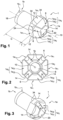
FIG. 1 is a perspective view of a nut according to the invention,
FIG. 2 is a front view of the nut,
FIG. 3 is another perspective view of the nut,
FIG. 4 is a cross-sectional view of the nut, a screw and a piston according to the invention,
FIG. 5 is a transverse view of a piston according to the invention,
FIG. 6 a is a transverse view of a brake caliper according to the invention.
FIG. 6 b is a diagram of the brake caliper comprising a nut, a screw and a piston according to the invention,
FIG. 6 c is a diagram of a braking device according to the invention comprising the brake caliper,
FIG. 7 is a cross-sectional view of the piston, and
FIG. 8 is a transverse view of the piston along the plane VII-VII of FIG. 7 .
FIG. 9 is a front view of the nut.
MORE DETAILED DESCRIPTION
As shown on FIGS. 1 and 3 , the nut 1 comprises two parts: a body C on most of its length and an end head T. The body has an external face having the shape of a straight circular cylinder of longitudinal axis 10. As shown on FIG. 2 , the nut is provided with an internal duct 8 opening out at each end 1 a and 1 b. It is therefore hollow. The duct also has the shape of a straight circular cylinder of longitudinal axis 10.
The end head T comprises several lateral faces 1 a 1 and several extremal faces 1 a 2.
The lateral faces 1 a 1 form an octagon around the axis 10. They can be flat, concave or convex. In this case, half of the faces 1 a 1 are flat and the other half are concave according to an alternate arrangement between the flat faces and the concave faces.
The extremal faces 1 a 2 form a pyramid with spherical faces of truncated octagonal base of height equal to the longitudinal axis 10. In other words, the extremal faces are partially spherical since they are part of a spherical cap. A spherical cap is in fact a spherical surface formed by the intersection of a sphere and a plane. In this case, the spherical cap forming the extremal faces 1 a 2 is formed by the intersection of a sphere whose centre belongs to the axis 10 and the plane containing the edges 12.
The extremal faces 1 a 2 are divided into two groups: a first group 1 a 21 and a second group 1 a 22. The set of extremal faces 1 a 2 is partially spherical, however the extremal faces 1 a 2 may be concave or convex. In this case, the faces 1 a 21 of the first group are concave and the faces 1 a 22 of the second group are convex. In the embodiment shown on FIGS. 1 to 3 , half of the extremal faces are convex and the other half are concave according to an alternate arrangement between the convex faces and the concave faces. Thus, the faces 1 a 22 are hollow unlike the faces 1 a 21 which are in relief.
As shown on FIG. 1 , the lateral and extremal faces have a common edge 12. In other words, the extremal 1 a 2 and lateral 1 a 1 faces are adjacent or contiguous. In addition, the flat lateral faces have an edge in common with the convex extremal faces while the concave lateral faces have an edge in common with the concave lateral faces.
The end head T is provided with several grooves 6. The grooves 6 open out onto the orifice forming the end of the duct 8 and each form a bearing surface 14 perpendicular to the axis 10. The grooves 6 are directed longitudinally along a first radius of longitudinal curvature. A radius of curvature of a curve is the radius of the curve osculating circle, also called the circle of curvature. This means that the radius of curvature is the radius of a circle following the curve as closely as possible. In this case, the radius of longitudinal curvature of the groove 6 has the same centre as the radius of curvature of the spherical cap. In addition, this radius is contained in the axis 10. In other words, the circle of curvature of the spherical cap and that of the longitudinal curvature of the groove are homothetic: one is the image of the other according to a homothety having a centre belonging to the axis 10. Furthermore, the grooves 6 are also directed longitudinally along a second radius of lateral curvature.
The number of grooves 6 is arbitrary. In this case, the end head T of the nut comprises four grooves, all identical to each other and arranged in a cross pattern as shown on FIG. 2 . Similarly, the radii of longitudinal curvature and the radii of lateral curvature are chosen depending on the circumstances. For example, the grooves 6 may each have identical radii of longitudinal curvature and different radii of lateral curvature, or vice versa. All the radii of curvature may also be identical from one groove to another, whether for the longitudinal curvatures or the lateral curvatures of the grooves 6. Furthermore, the radius of lateral or longitudinal curvature of a groove 6 may also vary along its length.
In this case, the grooves 6 are located on the convex faces 1 a 22. In other words, the faces 1 a 22 comprise the grooves 6, however, the grooves could be arranged on the concave faces 1 a 21. The grooves can be arranged according to other patterns: for example, they may be arranged according to the vertices of a regular polygon. Lastly, the curve defined by the points of the groove 6 having the smallest radial radius with respect to the axis 10 is a straight line according to this embodiment. This curve defines the path of the groove. Its geometry is generally arbitrary.
The other end 1 b of the nut 1 comprises a notch 18 in the body C of the nut. The notch has a main face 1 b extending in a plane radial to the axis 10.
The nut comprises a thread on the internal face 20 of the duct 8.
As shown on FIG. 4 , the nut is intended to receive a screw 3 in the duct 8. In addition, the nut 1 is intended to be inserted in a piston 2. The piston 2 is provided with a longitudinal internal duct 22 and, at one end, longitudinal 22 a and extremal 22 b internal faces having a common edge 26. The piston duct 22 is cylindrical with a circular cross-section. As shown on FIG. 5 , the orifice has a frustoconical shape at the closed end 28 of the piston, located on the right on FIGS. 4 and 5 . As shown on FIGS. 5 and 6 , the edge of the piston forming the entry of the orifice 22 is provided with an internal chamfer 32 at the other end 30. The screw 3 comprises an external thread adapted to cooperate with the internal thread of the nut 1. It comprises a frustoconical screw head of which an angle at the top of a head generation cone is equal to the angle of inclination of the internal chamfer of the edge of the piston.
As shown on FIG. 4 , the screw 3, the nut 1 and the piston 2 are arranged so that the common edge 12 of the lateral 1 a 1 and extremal 1 a 2 lateral faces is opposite the common edge 26 of the faces 22 a and 22 b of the piston. Thus, the extremal faces 1 a 2 of the nut 1 provide a sphere/cone support between the nut 1 and the piston 2.
In addition, the internal chamfer 32 of the edge of the piston is opposite the screw head 2 since the angles of inclination of the chamfer and of the truncated cone of the screw head are equal.
According to the invention, a brake caliper 16 shown on FIG. 6 a receives the screw 3, the nut 1 and the piston 2 in the same configuration as on FIG. 4 .
According to the invention, a braking device 4 shown on FIG. 6 c comprises the brake caliper 16.
We will now describe the operation of such a nut.
Once the nut 1 is inserted in the piston 2 as shown on FIG. 4 , the common edges 34 of the lateral faces 1 a 1 prevent the rotation of the nut 1 about the axis 10 relative to the piston 2. The lateral faces form a means of blocking the rotation of the nut 1 about the axis 10. The lateral faces 1 a 1 are therefore blocking faces. This blocking connects the piston 2 and the nut 1 together.
Thus, the rotation of the screw 3 relative to the caliper moves the nut 1 due to the shape complementarity between the external thread of the screw 3 and the internal thread of the nut 1. Since the nut 1 is connected to the piston 2, its translation causes the translation of the piston 2 by means of the extremal faces 1 a 2. The extremal faces 1 a 2 therefore form means for transmitting a linear force along the axis 10. This force transmission allows the transmission of a linear movement along the axis 10: the linear movement of the nut 1 along the axis 10 causes the linear movement of the piston 2 along the axis 10.
The grooves 6 form passages. They therefore favor the flow of brake fluid inside the piston.
We will now describe the advantages provided by the nut 1.
Since the transmission faces 1 a 2 and the blocking faces 1 a 1 have a common edge 12, the nut is smaller. For example, an outer diameter of the square of the nut is 26.05 mm instead of 29.65 mm. A length of an outer square 36, shown on FIG. 9 , of the nut is 23.05 mm (variation of 0.15 mm) instead of 26.65 mm (variation of 0.15 mm). The outer square is defined as being the square formed by the intersection, in a plane orthogonal to the axis 10, of straight lines tangential to the flat faces 1 a 1, as shown on FIG. 9 .
Such a nut therefore adapts to pistons of smaller dimensions. For example, a diameter of the bearing area between the means for blocking the rotation of the nut 1, in this case the lateral faces 1 a 1, and the piston 2 is 26 mm instead of 28 mm. Due to this space saving, the inner diameter of the piston square is 28.5 mm (possible variation of 0.2 mm) instead of 32.1 mm (same variation). Similarly, the diameter of the nut/piston bearing cone is 16.2 mm instead of 19.8 mm. Lastly, the diameter of the nut sphere formed by the extremal faces 1 a 2 is 16.2 mm instead of 19.8 mm.
Such a nut can be used with a smaller screw and piston without having to modify their geometries.
The nut is easier to machine. Since there is no collar, the number of manufacturing steps is reduced. In addition, the bearing areas 14 formed by the grooves make the nut easier to machine since they cooperate more easily with machining claws. Lastly, they allow manufacture using a stamping method.
The invention is not limited to the embodiments described and other embodiments will be clearly apparent to those skilled in the art.
  • 1—nut
  • 1 a—end of the nut
  • 1 a 1—lateral faces of the end head of the nut
  • 1 a 2—extremal faces of the end head of the nut
  • 1 a 21—concave extremal faces
  • 1 a 22—convex extremal faces
  • 1 b—other end of the nut
  • 1 b 1—face of the notch at the other end of the nut
  • 2—piston
  • 3—screw
  • 4—braking device
  • 6—groove
  • 8—longitudinal orifice of the nut
  • 10—longitudinal axis of the nut
  • 12—common edge of the lateral and extremal faces of the nut
  • 14—bearing area
  • 16—brake caliper
  • 18—notch
  • 20—face of the internal orifice of the nut
  • 22—longitudinal orifice of the piston
  • 22 a—longitudinal faces of the longitudinal orifice of the piston
  • 22 b—extremal faces of the longitudinal orifice of the piston
  • 24—contour of the bearing area
  • 26—common edge of the longitudinal and extremal faces of the piston
  • 28—closed end of the piston
  • 30—open end of the piston
  • 32—internal chamfer of the edge of the piston
  • 34—common edge of the lateral faces of the end head of the nut
  • 36—outer square of the nut
  • C—body of the nut
  • T—end head of the nut

Claims (10)

What is claimed is:
1. Nut, wherein one longitudinal end of the nut has:
at least one blocking face forming a means for blocking a rotation of the nut along a longitudinal axis of the nut, and
at least one transmission face forming a means for transmitting a force directed along the axis,
the at least one blocking face and the at least one transmission face having at least one common edge, and
the at least one blocking face being concave,
the nut comprising at least one groove crossing the at least one blocking face, wherein the at least one groove opens out onto a longitudinal orifice of the nut, wherein the at least one groove forms a bearing surface perpendicular to the axis.
2. Nut according to claim 1, wherein the groove is curved along its length.
3. Nut according to claim 1, wherein a contour of the bearing surface has at least one curved edge.
4. Nut according to claim 1 comprising several grooves, identical to each other.
5. Nut according to claim 4, wherein there are four grooves arranged in a cross pattern in a plane perpendicular to the axis.
6. Nut according to claim 1, wherein another longitudinal end of the nut has at least one other blocking face forming at least one other means for blocking the rotation of the nut with respect to a screw along the longitudinal axis.
7. Brake caliper comprising a nut according to claim 1.
8. Brake caliper according to claim 7 comprising:
a piston,
a screw, and the screw crossing the nut and the nut being inserted in the piston.
9. Braking device comprising a brake caliper according to claim 7.
10. Nut, wherein one longitudinal end of the nut has:
at least one blocking face forming a means for blocking a rotation of the nut along a longitudinal axis of the nut, and
at least one transmission face forming a means for transmitting a force directed along the axis,
the at least one blocking face and the at least one transmission face having at least one common edge, and
the at least one blocking face being concave,
the nut comprising at least one groove crossing the at least one blocking face, wherein the at least one groove opens out onto a longitudinal orifice of the nut, wherein the at least one groove forms a bearing surface perpendicular to the axis,
the at least one transmission face comprising a spherical part.
US16/982,921 2018-03-28 2019-03-27 Lock nut Active 2039-06-14 US11686360B2 (en)

Applications Claiming Priority (4)

Application Number Priority Date Filing Date Title
FR1852707A FR3079575B1 (en) 2018-03-28 2018-03-28 BRAKE NUT
FR18/52707 2018-03-28
FR1852707 2018-03-28
PCT/EP2019/057799 WO2019185759A1 (en) 2018-03-28 2019-03-27 Lock nut

Publications (2)

Publication Number Publication Date
US20210010553A1 US20210010553A1 (en) 2021-01-14
US11686360B2 true US11686360B2 (en) 2023-06-27

Family

ID=62223005

Family Applications (1)

Application Number Title Priority Date Filing Date
US16/982,921 Active 2039-06-14 US11686360B2 (en) 2018-03-28 2019-03-27 Lock nut

Country Status (6)

Country Link
US (1) US11686360B2 (en)
EP (1) EP3775597A1 (en)
JP (1) JP7598761B2 (en)
CN (1) CN111919045A (en)
FR (1) FR3079575B1 (en)
WO (1) WO2019185759A1 (en)

Families Citing this family (2)

* Cited by examiner, † Cited by third party
Publication number Priority date Publication date Assignee Title
CN111412231B (en) * 2020-03-26 2021-08-06 东风汽车集团有限公司 An anti-rotation structure of an electronic parking caliper piston
KR102868405B1 (en) * 2023-10-17 2025-10-13 주식회사 니프코코리아 Push nut with torsion improvement structure

Citations (8)

* Cited by examiner, † Cited by third party
Publication number Priority date Publication date Assignee Title
FR2496784A1 (en) 1980-12-22 1982-06-25 Securits France Ste Nle Lock nut for bolt - has conical extension with oval thread on standard nut
KR20130058263A (en) * 2011-11-25 2013-06-04 (주)영완 Disk brake for vehicle
US20140158480A1 (en) * 2012-12-12 2014-06-12 Chassis Brakes International B.V. Disk brake with a parking brake, mechanical thrust assembly, and method of assembling
CN205154857U (en) 2015-11-04 2016-04-13 浙江万向精工有限公司 A screw nut unit for electronic parking brake
KR20160053631A (en) * 2014-11-05 2016-05-13 주식회사 만도 An electronic disk brake
KR20170082276A (en) * 2016-01-06 2017-07-14 주식회사 만도 Electric caliper brake
CN107489714A (en) 2016-06-10 2017-12-19 株式会社万都 Electric pincer brake
FR3050493B1 (en) 2016-04-26 2018-05-25 Foundation Brakes France Sas LOW-COST NUT FOR VEHICLE BRAKING SYSTEM

Family Cites Families (7)

* Cited by examiner, † Cited by third party
Publication number Priority date Publication date Assignee Title
RU2418206C2 (en) * 2006-01-05 2011-05-10 Профиль-Фербиндунгстехник Гмбх Унд Ко. Кг Fastening element, subassembly, made of fastening element and sheet metal parts, and also method to fix fastening element onto sheet metal parts
US8832919B2 (en) * 2011-03-21 2014-09-16 Eca Medical Instruments Flanged ribbed nut
JP5699953B2 (en) * 2012-02-02 2015-04-15 トヨタ自動車株式会社 Electric parking brake device
ITMI20120220A1 (en) * 2012-02-15 2013-08-16 Freni Brembo Spa ELECTRIC PARKING BRAKE
DE102012003819A1 (en) * 2012-02-27 2013-08-29 Profil Verbindungstechnik Gmbh & Co. Kg Functional element for fluid-tight attachment to a sheet metal part, assembly part and method
CN108953426B (en) * 2016-08-29 2020-01-21 杭州萧冠机械有限公司 Processing method of driving assembly of parking brake caliper
CN206487744U (en) * 2017-01-18 2017-09-12 江苏易实精密科技股份有限公司 A kind of self-actuating brake clamp adjusting nut

Patent Citations (9)

* Cited by examiner, † Cited by third party
Publication number Priority date Publication date Assignee Title
FR2496784A1 (en) 1980-12-22 1982-06-25 Securits France Ste Nle Lock nut for bolt - has conical extension with oval thread on standard nut
KR20130058263A (en) * 2011-11-25 2013-06-04 (주)영완 Disk brake for vehicle
US20140158480A1 (en) * 2012-12-12 2014-06-12 Chassis Brakes International B.V. Disk brake with a parking brake, mechanical thrust assembly, and method of assembling
JP2015537175A (en) 2012-12-12 2015-12-24 シャシー・ブレークス・インターナショナル・ベスローテン・フェンノートシャップ Disc brake having parking brake, mechanical thrust assembly, and method of assembling the same
KR20160053631A (en) * 2014-11-05 2016-05-13 주식회사 만도 An electronic disk brake
CN205154857U (en) 2015-11-04 2016-04-13 浙江万向精工有限公司 A screw nut unit for electronic parking brake
KR20170082276A (en) * 2016-01-06 2017-07-14 주식회사 만도 Electric caliper brake
FR3050493B1 (en) 2016-04-26 2018-05-25 Foundation Brakes France Sas LOW-COST NUT FOR VEHICLE BRAKING SYSTEM
CN107489714A (en) 2016-06-10 2017-12-19 株式会社万都 Electric pincer brake

Non-Patent Citations (6)

* Cited by examiner, † Cited by third party
Title
Japanese Office Action for application JP 2020-552016, dated Feb. 7, 2023. Japan Patent Office, Tokyo, Japan.
Machine translation of KR 1020160053631 (no date). *
Machine translation of KR 20130058263 (no date). *
Machine translation of KR 2017082276 (no date). *
The First Chinese Office Action for Chinese Application No. 201980021827.1, dated: Jul. 23, 2021, The State ntellectual Property Office of People's Republic of China, Beijing City, China.
The International Search Report and The Written Opinion for PCT/EP2019/057799 of the International Searching Authority, dated Jun. 7, 2019, ISR/EPO, Rijswijk, The Netherlands.

Also Published As

Publication number Publication date
JP7598761B2 (en) 2024-12-12
CN111919045A (en) 2020-11-10
FR3079575B1 (en) 2020-07-17
US20210010553A1 (en) 2021-01-14
FR3079575A1 (en) 2019-10-04
EP3775597A1 (en) 2021-02-17
WO2019185759A1 (en) 2019-10-03
JP2021519403A (en) 2021-08-10

Similar Documents

Publication Publication Date Title
US11686360B2 (en) Lock nut
DE2264236C3 (en) Ball joint
EP1264114B1 (en) Constant velocity joint having fixed centre and crossed grooves
US6338589B1 (en) Hybrid ball stud
US20030194292A1 (en) Fastener including a screw and a supporting element
EP2602123A1 (en) An integrated hub-bearing assembly for the wheel of a motor vehicle
DE102015007743A1 (en) Thrust bearing and pneumatic shock absorber
US8141454B2 (en) Cable assembly with retainer
US6893010B2 (en) Sleeve, particularly a rod sleeve
JP2013507594A (en) Ball bearings and corresponding buffer parts
KR20170130492A (en) Double dome convex tire Ground plane block or ground plane rib
US4861316A (en) Constant velocity universal ball joint
GB2252138A (en) A thread seal
CN101836000B (en) Tripod joint and roller body for a tripod joint
WO2016039307A1 (en) Linear motion rod, linking member, piston, and piston-fastening structure
US20130095932A1 (en) Constant-velocity ball joint
SE447089B (en) DOUBLE CIRCUIT PRESSURE VALVE FOR HYDRAULIC BRAKE SYSTEM
WO2017167961A1 (en) Tilting pad bearing
US6401755B2 (en) Damping valve
US7841948B2 (en) Cross groove type constant velocity joint
EP3483028B1 (en) Levelling system for a vehicle, in particular a rail vehicle
GB1561870A (en) Self-pressuring bearing
US8919753B2 (en) Spring plate
US12305703B2 (en) Tapered roller bearing and cage
KR20100016035A (en) Vibration damper

Legal Events

Date Code Title Description
FEPP Fee payment procedure

Free format text: ENTITY STATUS SET TO UNDISCOUNTED (ORIGINAL EVENT CODE: BIG.); ENTITY STATUS OF PATENT OWNER: LARGE ENTITY

AS Assignment

Owner name: FOUNDATION BRAKES FRANCE SAS, FRANCE

Free format text: ASSIGNMENT OF ASSIGNORS INTEREST;ASSIGNORS:PINTO, ROSA;BERTRAND, JEROME;UMBDENSTOCK, FABRICE;AND OTHERS;SIGNING DATES FROM 20200917 TO 20200918;REEL/FRAME:053932/0230

STPP Information on status: patent application and granting procedure in general

Free format text: APPLICATION DISPATCHED FROM PREEXAM, NOT YET DOCKETED

STPP Information on status: patent application and granting procedure in general

Free format text: DOCKETED NEW CASE - READY FOR EXAMINATION

STPP Information on status: patent application and granting procedure in general

Free format text: NON FINAL ACTION MAILED

STPP Information on status: patent application and granting procedure in general

Free format text: RESPONSE TO NON-FINAL OFFICE ACTION ENTERED AND FORWARDED TO EXAMINER

STPP Information on status: patent application and granting procedure in general

Free format text: NON FINAL ACTION MAILED

STCF Information on status: patent grant

Free format text: PATENTED CASE