US11651614B2 - Pixel driving circuit, driving method thereof and display panel - Google Patents
Pixel driving circuit, driving method thereof and display panel Download PDFInfo
- Publication number
- US11651614B2 US11651614B2 US17/431,437 US202117431437A US11651614B2 US 11651614 B2 US11651614 B2 US 11651614B2 US 202117431437 A US202117431437 A US 202117431437A US 11651614 B2 US11651614 B2 US 11651614B2
- Authority
- US
- United States
- Prior art keywords
- transistor
- electrode
- node
- signal
- unit
- Prior art date
- Legal status (The legal status is an assumption and is not a legal conclusion. Google has not performed a legal analysis and makes no representation as to the accuracy of the status listed.)
- Active, expires
Links
Images


Classifications
-
- G—PHYSICS
- G09—EDUCATION; CRYPTOGRAPHY; DISPLAY; ADVERTISING; SEALS
- G09G—ARRANGEMENTS OR CIRCUITS FOR CONTROL OF INDICATING DEVICES USING STATIC MEANS TO PRESENT VARIABLE INFORMATION
- G09G3/00—Control arrangements or circuits, of interest only in connection with visual indicators other than cathode-ray tubes
- G09G3/20—Control arrangements or circuits, of interest only in connection with visual indicators other than cathode-ray tubes for presentation of an assembly of a number of characters, e.g. a page, by composing the assembly by combination of individual elements arranged in a matrix no fixed position being assigned to or needed to be assigned to the individual characters or partial characters
- G09G3/22—Control arrangements or circuits, of interest only in connection with visual indicators other than cathode-ray tubes for presentation of an assembly of a number of characters, e.g. a page, by composing the assembly by combination of individual elements arranged in a matrix no fixed position being assigned to or needed to be assigned to the individual characters or partial characters using controlled light sources
- G09G3/30—Control arrangements or circuits, of interest only in connection with visual indicators other than cathode-ray tubes for presentation of an assembly of a number of characters, e.g. a page, by composing the assembly by combination of individual elements arranged in a matrix no fixed position being assigned to or needed to be assigned to the individual characters or partial characters using controlled light sources using electroluminescent panels
- G09G3/32—Control arrangements or circuits, of interest only in connection with visual indicators other than cathode-ray tubes for presentation of an assembly of a number of characters, e.g. a page, by composing the assembly by combination of individual elements arranged in a matrix no fixed position being assigned to or needed to be assigned to the individual characters or partial characters using controlled light sources using electroluminescent panels semiconductive, e.g. using light-emitting diodes [LED]
- G09G3/3208—Control arrangements or circuits, of interest only in connection with visual indicators other than cathode-ray tubes for presentation of an assembly of a number of characters, e.g. a page, by composing the assembly by combination of individual elements arranged in a matrix no fixed position being assigned to or needed to be assigned to the individual characters or partial characters using controlled light sources using electroluminescent panels semiconductive, e.g. using light-emitting diodes [LED] organic, e.g. using organic light-emitting diodes [OLED]
- G09G3/3225—Control arrangements or circuits, of interest only in connection with visual indicators other than cathode-ray tubes for presentation of an assembly of a number of characters, e.g. a page, by composing the assembly by combination of individual elements arranged in a matrix no fixed position being assigned to or needed to be assigned to the individual characters or partial characters using controlled light sources using electroluminescent panels semiconductive, e.g. using light-emitting diodes [LED] organic, e.g. using organic light-emitting diodes [OLED] using an active matrix
- G09G3/3233—Control arrangements or circuits, of interest only in connection with visual indicators other than cathode-ray tubes for presentation of an assembly of a number of characters, e.g. a page, by composing the assembly by combination of individual elements arranged in a matrix no fixed position being assigned to or needed to be assigned to the individual characters or partial characters using controlled light sources using electroluminescent panels semiconductive, e.g. using light-emitting diodes [LED] organic, e.g. using organic light-emitting diodes [OLED] using an active matrix with pixel circuitry controlling the current through the light-emitting element
-
- G—PHYSICS
- G09—EDUCATION; CRYPTOGRAPHY; DISPLAY; ADVERTISING; SEALS
- G09G—ARRANGEMENTS OR CIRCUITS FOR CONTROL OF INDICATING DEVICES USING STATIC MEANS TO PRESENT VARIABLE INFORMATION
- G09G3/00—Control arrangements or circuits, of interest only in connection with visual indicators other than cathode-ray tubes
- G09G3/20—Control arrangements or circuits, of interest only in connection with visual indicators other than cathode-ray tubes for presentation of an assembly of a number of characters, e.g. a page, by composing the assembly by combination of individual elements arranged in a matrix no fixed position being assigned to or needed to be assigned to the individual characters or partial characters
-
- G—PHYSICS
- G06—COMPUTING OR CALCULATING; COUNTING
- G06V—IMAGE OR VIDEO RECOGNITION OR UNDERSTANDING
- G06V40/00—Recognition of biometric, human-related or animal-related patterns in image or video data
- G06V40/10—Human or animal bodies, e.g. vehicle occupants or pedestrians; Body parts, e.g. hands
- G06V40/12—Fingerprints or palmprints
- G06V40/13—Sensors therefor
- G06V40/1306—Sensors therefor non-optical, e.g. ultrasonic or capacitive sensing
-
- G—PHYSICS
- G09—EDUCATION; CRYPTOGRAPHY; DISPLAY; ADVERTISING; SEALS
- G09G—ARRANGEMENTS OR CIRCUITS FOR CONTROL OF INDICATING DEVICES USING STATIC MEANS TO PRESENT VARIABLE INFORMATION
- G09G3/00—Control arrangements or circuits, of interest only in connection with visual indicators other than cathode-ray tubes
- G09G3/20—Control arrangements or circuits, of interest only in connection with visual indicators other than cathode-ray tubes for presentation of an assembly of a number of characters, e.g. a page, by composing the assembly by combination of individual elements arranged in a matrix no fixed position being assigned to or needed to be assigned to the individual characters or partial characters
- G09G3/22—Control arrangements or circuits, of interest only in connection with visual indicators other than cathode-ray tubes for presentation of an assembly of a number of characters, e.g. a page, by composing the assembly by combination of individual elements arranged in a matrix no fixed position being assigned to or needed to be assigned to the individual characters or partial characters using controlled light sources
- G09G3/30—Control arrangements or circuits, of interest only in connection with visual indicators other than cathode-ray tubes for presentation of an assembly of a number of characters, e.g. a page, by composing the assembly by combination of individual elements arranged in a matrix no fixed position being assigned to or needed to be assigned to the individual characters or partial characters using controlled light sources using electroluminescent panels
- G09G3/32—Control arrangements or circuits, of interest only in connection with visual indicators other than cathode-ray tubes for presentation of an assembly of a number of characters, e.g. a page, by composing the assembly by combination of individual elements arranged in a matrix no fixed position being assigned to or needed to be assigned to the individual characters or partial characters using controlled light sources using electroluminescent panels semiconductive, e.g. using light-emitting diodes [LED]
- G09G3/3208—Control arrangements or circuits, of interest only in connection with visual indicators other than cathode-ray tubes for presentation of an assembly of a number of characters, e.g. a page, by composing the assembly by combination of individual elements arranged in a matrix no fixed position being assigned to or needed to be assigned to the individual characters or partial characters using controlled light sources using electroluminescent panels semiconductive, e.g. using light-emitting diodes [LED] organic, e.g. using organic light-emitting diodes [OLED]
- G09G3/3225—Control arrangements or circuits, of interest only in connection with visual indicators other than cathode-ray tubes for presentation of an assembly of a number of characters, e.g. a page, by composing the assembly by combination of individual elements arranged in a matrix no fixed position being assigned to or needed to be assigned to the individual characters or partial characters using controlled light sources using electroluminescent panels semiconductive, e.g. using light-emitting diodes [LED] organic, e.g. using organic light-emitting diodes [OLED] using an active matrix
-
- G—PHYSICS
- G09—EDUCATION; CRYPTOGRAPHY; DISPLAY; ADVERTISING; SEALS
- G09G—ARRANGEMENTS OR CIRCUITS FOR CONTROL OF INDICATING DEVICES USING STATIC MEANS TO PRESENT VARIABLE INFORMATION
- G09G3/00—Control arrangements or circuits, of interest only in connection with visual indicators other than cathode-ray tubes
- G09G3/20—Control arrangements or circuits, of interest only in connection with visual indicators other than cathode-ray tubes for presentation of an assembly of a number of characters, e.g. a page, by composing the assembly by combination of individual elements arranged in a matrix no fixed position being assigned to or needed to be assigned to the individual characters or partial characters
- G09G3/22—Control arrangements or circuits, of interest only in connection with visual indicators other than cathode-ray tubes for presentation of an assembly of a number of characters, e.g. a page, by composing the assembly by combination of individual elements arranged in a matrix no fixed position being assigned to or needed to be assigned to the individual characters or partial characters using controlled light sources
- G09G3/30—Control arrangements or circuits, of interest only in connection with visual indicators other than cathode-ray tubes for presentation of an assembly of a number of characters, e.g. a page, by composing the assembly by combination of individual elements arranged in a matrix no fixed position being assigned to or needed to be assigned to the individual characters or partial characters using controlled light sources using electroluminescent panels
- G09G3/32—Control arrangements or circuits, of interest only in connection with visual indicators other than cathode-ray tubes for presentation of an assembly of a number of characters, e.g. a page, by composing the assembly by combination of individual elements arranged in a matrix no fixed position being assigned to or needed to be assigned to the individual characters or partial characters using controlled light sources using electroluminescent panels semiconductive, e.g. using light-emitting diodes [LED]
- G09G3/3208—Control arrangements or circuits, of interest only in connection with visual indicators other than cathode-ray tubes for presentation of an assembly of a number of characters, e.g. a page, by composing the assembly by combination of individual elements arranged in a matrix no fixed position being assigned to or needed to be assigned to the individual characters or partial characters using controlled light sources using electroluminescent panels semiconductive, e.g. using light-emitting diodes [LED] organic, e.g. using organic light-emitting diodes [OLED]
- G09G3/3275—Details of drivers for data electrodes
-
- G—PHYSICS
- G09—EDUCATION; CRYPTOGRAPHY; DISPLAY; ADVERTISING; SEALS
- G09G—ARRANGEMENTS OR CIRCUITS FOR CONTROL OF INDICATING DEVICES USING STATIC MEANS TO PRESENT VARIABLE INFORMATION
- G09G2300/00—Aspects of the constitution of display devices
- G09G2300/04—Structural and physical details of display devices
- G09G2300/0421—Structural details of the set of electrodes
- G09G2300/0426—Layout of electrodes and connections
-
- G—PHYSICS
- G09—EDUCATION; CRYPTOGRAPHY; DISPLAY; ADVERTISING; SEALS
- G09G—ARRANGEMENTS OR CIRCUITS FOR CONTROL OF INDICATING DEVICES USING STATIC MEANS TO PRESENT VARIABLE INFORMATION
- G09G2300/00—Aspects of the constitution of display devices
- G09G2300/08—Active matrix structure, i.e. with use of active elements, inclusive of non-linear two terminal elements, in the pixels together with light emitting or modulating elements
- G09G2300/0809—Several active elements per pixel in active matrix panels
- G09G2300/0819—Several active elements per pixel in active matrix panels used for counteracting undesired variations, e.g. feedback or autozeroing
-
- G—PHYSICS
- G09—EDUCATION; CRYPTOGRAPHY; DISPLAY; ADVERTISING; SEALS
- G09G—ARRANGEMENTS OR CIRCUITS FOR CONTROL OF INDICATING DEVICES USING STATIC MEANS TO PRESENT VARIABLE INFORMATION
- G09G2300/00—Aspects of the constitution of display devices
- G09G2300/08—Active matrix structure, i.e. with use of active elements, inclusive of non-linear two terminal elements, in the pixels together with light emitting or modulating elements
- G09G2300/0809—Several active elements per pixel in active matrix panels
- G09G2300/0842—Several active elements per pixel in active matrix panels forming a memory circuit, e.g. a dynamic memory with one capacitor
- G09G2300/0852—Several active elements per pixel in active matrix panels forming a memory circuit, e.g. a dynamic memory with one capacitor being a dynamic memory with more than one capacitor
-
- G—PHYSICS
- G09—EDUCATION; CRYPTOGRAPHY; DISPLAY; ADVERTISING; SEALS
- G09G—ARRANGEMENTS OR CIRCUITS FOR CONTROL OF INDICATING DEVICES USING STATIC MEANS TO PRESENT VARIABLE INFORMATION
- G09G2300/00—Aspects of the constitution of display devices
- G09G2300/08—Active matrix structure, i.e. with use of active elements, inclusive of non-linear two terminal elements, in the pixels together with light emitting or modulating elements
- G09G2300/0809—Several active elements per pixel in active matrix panels
- G09G2300/0842—Several active elements per pixel in active matrix panels forming a memory circuit, e.g. a dynamic memory with one capacitor
- G09G2300/0861—Several active elements per pixel in active matrix panels forming a memory circuit, e.g. a dynamic memory with one capacitor with additional control of the display period without amending the charge stored in a pixel memory, e.g. by means of additional select electrodes
-
- G—PHYSICS
- G09—EDUCATION; CRYPTOGRAPHY; DISPLAY; ADVERTISING; SEALS
- G09G—ARRANGEMENTS OR CIRCUITS FOR CONTROL OF INDICATING DEVICES USING STATIC MEANS TO PRESENT VARIABLE INFORMATION
- G09G2320/00—Control of display operating conditions
- G09G2320/02—Improving the quality of display appearance
- G09G2320/0238—Improving the black level
-
- G—PHYSICS
- G09—EDUCATION; CRYPTOGRAPHY; DISPLAY; ADVERTISING; SEALS
- G09G—ARRANGEMENTS OR CIRCUITS FOR CONTROL OF INDICATING DEVICES USING STATIC MEANS TO PRESENT VARIABLE INFORMATION
- G09G2330/00—Aspects of power supply; Aspects of display protection and defect management
- G09G2330/02—Details of power systems and of start or stop of display operation
- G09G2330/028—Generation of voltages supplied to electrode drivers in a matrix display other than LCD
-
- G—PHYSICS
- G09—EDUCATION; CRYPTOGRAPHY; DISPLAY; ADVERTISING; SEALS
- G09G—ARRANGEMENTS OR CIRCUITS FOR CONTROL OF INDICATING DEVICES USING STATIC MEANS TO PRESENT VARIABLE INFORMATION
- G09G2354/00—Aspects of interface with display user
Definitions
- Embodiments of the present disclosure relate to, but are not limited to, the field of display technology, in particular to a pixel driving circuit, a driving method thereof and a display panel.
- Fingerprint identification is a biometric approach, which has been widely applied in smart phones, security devices and other fields.
- common fingerprint identification approaches include optical identification, capacitive identification and ultrasonic identification.
- Ultrasonic fingerprint identification has attracted much attention for its good penetration, high accuracy, underwater unlocking and living body identification.
- the display modules have independent display circuits and logic circuit structures, and the ultrasonic fingerprint sensors are usually attached to the lower sides of the display panels in the form of plug-in modules, which not only leads to the large overall thickness of the display modules, but also leads to the high power consumption of the display modules.
- An embodiment of the present disclosure provides a pixel driving circuit, a driving method thereof and a display panel.
- an embodiment of the present disclosure provides a pixel driving circuit, including a pixel driving module, an ultrasonic driving unit, an ultrasonic sensing unit and a signal acquisition unit.
- the pixel driving module is respectively connected with a first power supply terminal, a first signal terminal, a second signal terminal, a data input terminal and a first electrode of a light-emitting unit, and is configured to provide a driving signal to the first electrode of the light-emitting unit according to signals of the first power supply terminal and the data input terminal under the control of the first signal terminal and the second signal terminal.
- the ultrasonic driving unit is respectively connected with the second signal terminal and a first node, and is configured to provide a signal of the second signal terminal to the first node under the control of the second signal terminal.
- a first electrode of the ultrasonic sensing unit is connected with the first node, and a second electrode of the ultrasonic sensing unit is connected with a third power supply terminal; the ultrasonic sensing unit is configured to transmit ultrasonic waves according to signals of the first node and the third power supply terminal, receive reflected ultrasonic echoes and generate a first induction signal at the first node.
- the signal acquisition unit is respectively connected with the first power supply terminal, the first node and an output terminal, and is configured to output a second induction signal to the output terminal according to the first power supply terminal and the first induction signal under the control of the first induction signal of the first node.
- the pixel driving module includes a charging unit, a storage unit, a writing unit, a driving unit and a control unit.
- the charging unit is respectively connected with the first power supply terminal, the first signal terminal, the second signal terminal, a second node and a fourth node; the charging unit is configured to provide a signal of the first power supply terminal to the second node through the fourth node under control of the first signal terminal and the second signal terminal; the charging unit is further configured to provide the signal of the first power supply terminal to the fourth node under control of the first signal terminal and the second signal terminal.
- a first electrode of the storage unit is connected with the second node, and a second electrode of the storage unit is connected with the first electrode of the light-emitting unit; the storage unit is configured to store a signal of the second node.
- the writing unit is respectively connected with the second signal terminal, the data input terminal and a third node, and is configured to provide a signal of the data input terminal to the third node under control of the second signal terminal.
- the driving unit is respectively connected with the second node, the fourth node and the third node, the driving unit is configured to provide a signal of the third node to the second node under control of the second node, and the driving unit is further configured to make the fourth node and the third node be on under control of the second node.
- the control unit is respectively connected with the third node, the first signal terminal and the first electrode of the light-emitting unit, and is configured to make the third node and the first electrode of the light-emitting unit be on under control of the first signal terminal.
- the pixel driving circuit further includes a resetting unit, the resetting unit is respectively connected with the first signal terminal, a fourth power supply terminal and the first electrode of the light-emitting unit, and the resetting unit is configured to provide a signal of the fourth power supply terminal to the first electrode of the light-emitting unit under control of the first signal terminal.
- the charging unit includes a first transistor and a second transistor; a control electrode of the first transistor is connected with the second signal terminal, a first electrode of the first transistor is connected with the first power supply terminal, and a second electrode of the first transistor is connected with the fourth node; a control electrode of the second transistor is connected with the first signal terminal, a first electrode of the second transistor is connected with the fourth node, and a second electrode of the second transistor is connected with the second node.
- the writing unit includes a third transistor, a control electrode of the third transistor is connected with the second signal terminal, a first electrode of the third transistor is connected with the data input terminal, and a second electrode of the third transistor is connected with the third node.
- the driving unit includes a fourth transistor, a control electrode of the fourth transistor is connected with the second node, a first electrode of the fourth transistor is connected with the fourth node, and a second electrode of the fourth transistor is connected with the third node.
- control unit includes a fifth transistor, a control electrode of the fifth transistor is connected with the first signal terminal, a first electrode of the fifth transistor is connected with the third node, and a second electrode of the fifth transistor is connected with the first electrode of the light-emitting unit.
- the resetting unit includes a sixth transistor, a control electrode of the sixth transistor is connected with the first signal terminal, a first electrode of the sixth transistor is connected with the fourth power supply terminal, and a second electrode of the sixth transistor is connected with the first electrode of the light-emitting unit.
- the ultrasonic driving unit includes a seventh transistor, a control electrode and a first electrode of the seventh transistor are connected with the second signal terminal, and a second electrode of the seventh transistor is connected with the first node.
- the signal acquisition unit includes an eighth transistor, a control electrode of the eighth transistor is connected with the first node, a first electrode of the eighth transistor is connected with the first power supply terminal, and a second electrode of the eighth transistor is connected with the output terminal.
- the signal acquisition unit further includes a ninth transistor located between the eighth transistor and the output terminal, a control electrode of the ninth transistor is connected with the first signal terminal, a first electrode of the ninth transistor is connected with the second electrode of the eighth transistor, and a second electrode of the ninth transistor is connected with the output terminal.
- the pixel driving circuit further includes a resetting unit, the resetting unit includes a sixth transistor, the charging unit includes a first transistor and a second transistor, the storage unit includes a storage capacitor, the writing unit includes a third transistor, the driving unit includes a fourth transistor, the control unit includes a fifth transistor, the ultrasonic driving unit includes a seventh transistor, the signal acquisition unit includes an eighth transistor and a ninth transistor, and the light-emitting unit includes an organic light-emitting diode.
- a control electrode of the first transistor is connected with the second signal terminal, a first electrode of the first transistor is connected with the first power supply terminal, and a second electrode of the first transistor is connected with the fourth node.
- a control electrode of the second transistor is connected with the first signal terminal, a first electrode of the second transistor is connected with the fourth node, and a second electrode of the second transistor is connected with the second node.
- a control electrode of the third transistor is connected with the second signal terminal, a first electrode of the third transistor is connected with the data input terminal, and a second electrode of the third transistor is connected with the third node.
- a control electrode of the fourth transistor is connected with the second node, a first electrode of the fourth transistor is connected with the fourth node, and a second electrode of the fourth transistor is connected with the third node.
- a control electrode of the fifth transistor is connected with the first signal terminal, a first electrode of the fifth transistor is connected with the third node, and a second electrode of the fifth transistor is connected with the first electrode of the organic light-emitting diode.
- a second electrode of the organic light-emitting diode is connected with the second power supply terminal.
- a first electrode plate of the storage capacitor is connected with the second node, and a second electrode plate of the storage capacitor is connected with a first electrode of the organic light-emitting diode.
- a control electrode of the sixth transistor is connected with the first signal terminal, a first electrode of the sixth transistor is connected with the fourth power supply terminal, and a second electrode of the sixth transistor is connected with the first electrode of the organic light-emitting diode.
- a control electrode and a first electrode of the seventh transistor are connected with the second signal terminal, and a second electrode of the seventh transistor is connected with the first node.
- a control electrode of the eighth transistor is connected with the first node, a first electrode of the eighth transistor is connected with the first power supply terminal, and a second electrode of the eighth transistor is connected with a first electrode of the ninth transistor.
- a control electrode of the ninth transistor is connected with the first signal terminal, and a second electrode of the ninth transistor is connected with the output terminal.
- a first electrode of the ultrasonic sensing unit is connected with the first node, and a second electrode of the ultrasonic sensing unit is connected with the third power supply terminal.
- an embodiment of the present disclosure further provides a driving method of a pixel driving circuit, which is applied to the pixel driving circuit described above and includes: in a first stage, providing a signal of the first power supply terminal to a second node, providing a signal of the second signal terminal to the first node, and transmitting, by the ultrasonic sensing unit, ultrasonic waves; in a second stage, providing a signal of the data input terminal to a third node and compensating a voltage of the second node; receiving reflected ultrasonic echoes and generating a first induction signal at the first node; outputting a second induction signal to the output terminal under control of the first induction signal of the first node; and in a third stage, conducting the first power supply terminal and a second power supply terminal through a charging unit, a driving unit, a control unit and a light-emitting unit.
- the method further includes: in the first stage, providing a signal of a fourth power supply terminal to a first electrode of the light-emitting unit.
- an embodiment of the present disclosure further provides a display panel, including a plurality of the pixel driving circuits described above.
- FIG. 1 illustrates a schematic diagram of a structure of a display module with an ultrasonic fingerprint sensor.
- FIG. 2 illustrates a schematic diagram of a structure of an Organic Light-Emitting Diode (OLED) display module.
- OLED Organic Light-Emitting Diode
- FIG. 3 illustrates a schematic diagram of a pixel driving circuit in an exemplary embodiment of the present disclosure.
- FIG. 4 illustrates a schematic diagram of a pixel driving circuit in another exemplary embodiment of the present disclosure.
- FIG. 5 illustrates an equivalent schematic diagram of a charging unit in an exemplary embodiment of the present disclosure.
- FIG. 6 illustrates an equivalent schematic diagram of a writing unit in an exemplary embodiment of the present disclosure.
- FIG. 7 illustrates an equivalent schematic diagram of a driving unit in an exemplary embodiment of the present disclosure.
- FIG. 8 illustrates an equivalent schematic diagram of a control unit in an exemplary embodiment of the present disclosure.
- FIG. 9 illustrates an equivalent schematic diagram of a resetting unit in an exemplary embodiment of the present disclosure.
- FIG. 10 illustrates an equivalent schematic diagram of an ultrasonic driving unit in an exemplary embodiment of the present disclosure.
- FIG. 11 illustrates an equivalent schematic diagram of a signal acquisition unit in an exemplary embodiment of the present disclosure.
- FIG. 12 illustrates an equivalent schematic diagram of a signal acquisition unit in another exemplary embodiment of the present disclosure.
- FIG. 13 illustrates an equivalent schematic diagram of a pixel driving circuit in an exemplary embodiment of the present disclosure.
- FIG. 14 illustrates a timing schematic diagram of a pixel driving circuit in an exemplary embodiment of the present disclosure.
- FIG. 15 illustrates a schematic diagram of a state of a pixel driving circuit in a first stage in an exemplary embodiment of the present disclosure.
- FIG. 16 illustrates a schematic diagram of a state of a pixel driving circuit in a second stage in an exemplary embodiment of the present disclosure.
- FIG. 17 illustrates a schematic diagram of a state of a pixel driving circuit in a third stage in an exemplary embodiment of the present disclosure.
- FIG. 18 illustrates a schematic diagram of a driving method of a pixel driving circuit in an exemplary embodiment of the present disclosure.
- the present disclosure includes and envisages combinations with features and elements known to those of ordinary skill in the art.
- the embodiments, features and elements already disclosed in the present disclosure may be combined with any conventional features or elements to form a unique solution defined by the claims.
- Any feature or element of any embodiment may be combined with features or elements from other solutions to form another unique solution defined by the claims. Therefore, it should be understood that any features shown and/or discussed in the present disclosure may be implemented individually or in any appropriate combination. Therefore, the embodiments are not subject to other limitations except those made according to the appended claims and their equivalent replacements.
- various modifications and changes may be made within the scope of protection of the appended claims.
- the specification may have presented the method and/or process as a specific sequence of acts. However, to the extent that the method or process does not depend on the specific order of acts described herein, the method or process should not be limited to the specific order of acts described herein. As will be understood by those of ordinary skill in the art, other act orders are possible. Therefore, the specific order of acts set forth in the specification should not be interpreted as limiting the claims. In addition, the claims for the method and/or process should not be limited to performing their acts in the written order. Those skilled in the art can easily understand that these orders may be changed and remain within the spirit and scope of the embodiments of the present disclosure.
- Words such as “first” and “second” used in the embodiments of the present disclosure do not mean any order, quantity or importance, but are only used to distinguish different components. Words such as “including” or “comprising” mean that the element or object appearing before the word covers the elements or objects listed after the word and their equivalents, and do not exclude other elements or objects. Words such as “connect” or “connected” are not limited to physical or mechanical connection, but may include electrical connection, whether direct or indirect.
- the transistors used in all embodiments of the present disclosure may be thin film transistors, field effect transistors or other devices with the same characteristics.
- the thin film transistors used in the embodiments of the present disclosure may be oxide semiconductor transistors. Since the source and drain of the transistor used here are symmetrical, the source and drain may be interchanged.
- the gate of the transistor is called a control electrode. In order to distinguish the two electrodes of the transistor other than the gate, one of them is called first electrode and the other is called second electrode.
- the first electrode may be a source or drain, and the second electrode may be a drain or source.
- FIG. 1 illustrates a schematic diagram of a structure of a display module with an ultrasonic fingerprint sensor.
- the display module may include an ultrasonic fingerprint sensor 20 .
- the display module may further include a substrate 21 .
- the ultrasonic fingerprint sensor 20 may include a first electrode layer 22 disposed on an upper side of the substrate 21 , a piezoelectric material layer 23 disposed on an upper side of the first electrode layer 22 , and a second electrode layer 24 disposed on an upper side of the piezoelectric material layer 23 .
- the display module may further include a flexible circuit board 11 located on a lower side of the substrate 21 after bending, and a signal processing chip 12 disposed on the flexible circuit board 11 .
- FIG. 1 illustrates a schematic diagram of a structure of a display module with an ultrasonic fingerprint sensor.
- the display module may include an ultrasonic fingerprint sensor 20 .
- the display module may further include a substrate 21 .
- the ultrasonic fingerprint sensor 20 may include a first electrode layer 22 disposed
- the ultrasonic fingerprint sensor 20 is attached to a lower side of the display panel 10 in the form of a plug-in module.
- the display module has an independent display circuit and logic circuit structure. Therefore, the display module illustrated in FIG. 1 not only increases the overall thickness of the display module, but also increases the power consumption of the display module.
- FIG. 2 is a schematic diagram of a structure of an OLED display module.
- the OLED display module may include a pixel driving module 30 , an ultrasonic fingerprint sensor 20 and a flexible circuit board 11 .
- the ultrasonic fingerprint sensor 20 may include a first electrode layer 22 disposed on a lower side of the pixel driving module 30 , a piezoelectric material layer 23 disposed on a lower side of the first electrode layer 22 , and a second electrode layer 24 disposed on a lower side of the piezoelectric material layer 23 .
- the flexible circuit board 11 is located on a lower side of the second electrode layer 24 after bending, and a signal processing chip 12 is disposed on a lower side of the flexible circuit board 11 .
- a signal processing chip 12 is disposed on a lower side of the flexible circuit board 11 .
- an echo acquisition circuit of the ultrasonic fingerprint sensor 20 and a pixel driving circuit are integrated in the display panel.
- the overall thickness of the display module illustrated in FIG. 2 is much smaller than that of the display module illustrated in FIG. 1 , the display area circuit and gate driving circuit of the display module illustrated in FIG. 2 are complex, the thickness of the display module is still large, and it is difficult to achieve high PPI (Pixels Per Inch) and a narrow frame.
- the pixel driving circuit may include three stages, namely, a first stage T 1 , a second stage T 2 and a third stage T 3 .
- the first stage T 1 may be called a pixel charging and ultrasonic transmission stage
- the second stage T 2 may be called a writing compensation and echo acquisition stage
- the third stage T 3 may be called a pixel luminescence stage.
- FIG. 3 illustrates a schematic diagram of a pixel driving circuit in an exemplary embodiment of the present disclosure.
- the pixel driving circuit may include a pixel driving module 40 , an ultrasonic driving unit 60 , an ultrasonic sensing unit 70 , and a signal acquisition unit 80 .
- the pixel driving module 40 is respectively connected with a first power supply terminal VDD, a first signal terminal SCAN 1 , a second signal terminal SCAN 2 , a data input terminal Vdata and a first electrode of a light-emitting unit 50 .
- the pixel driving module 40 is configured to provide a driving signal to the first electrode of the light-emitting unit 50 according to signals of the first power supply terminal VDD and the data input terminal Vdata under the control of the first signal terminal SCAN 1 and the second signal terminal SCAN 2 , so as to drive the light-emitting unit 50 to emit light.
- the first electrode of the light-emitting unit 50 is connected with the pixel driving module 40 , and a second electrode of the light-emitting unit 50 is connected with a second power supply terminal VSS.
- the light-emitting unit 50 is configured to emit light under the control of the pixel driving module 40 and the second power supply terminal VSS.
- the first electrode of the light-emitting unit 50 may be an anode and the second electrode thereof may be a cathode.
- the ultrasonic driving unit 60 is respectively connected with the second signal terminal SCAN 2 and a first node B.
- the ultrasonic driving unit 60 is configured to provide a signal of the second signal terminal SCAN 2 to the first node B under the control of the second signal terminal SCAN 2 .
- a first electrode of the ultrasonic sensing unit 70 is connected with the first node B, and a second electrode of the ultrasonic sensing unit 70 is connected with a third power supply terminal Tx.
- the ultrasonic sensing unit 70 is configured to transmit ultrasonic waves according to the signals of the first node B and the third power supply terminal Tx, receive reflected ultrasonic echoes, and generate a first induction signal at the first node B.
- the signal acquisition unit 80 is respectively connected with the first power supply terminal VDD, the first node B and an output terminal OUT.
- the signal acquisition unit 80 is configured to output a second induction signal to the output terminal OUT according to the first power supply terminal VDD and the first induction signal of the first node B under the control of the first induction signal of the first node B.
- the pixel driving circuit integrateds an ultrasonic fingerprint identification function into the pixel driving circuit, reduces circuit complexity of the display area and GOA (Gate Driver on Array) area in the display panel, thereby reducing the overall thickness of the display panel, reducing the power consumption of the display panel, thereby beneficial to achieve high PPI and narrow frame of the display panel.
- GOA Gate Driver on Array
- FIG. 4 illustrates a schematic diagram of a pixel driving circuit in another exemplary embodiment of the present disclosure.
- the pixel driving module 40 may include a charging unit 41 , a storage unit 42 , a driving unit 43 , a writing unit 44 , and a control unit 45 .
- the charging unit 41 is respectively connected with the first power supply terminal VDD, the first signal terminal SCAN 1 , the second signal terminal SCAN 2 , a second node A, and a fourth node D.
- the charging unit 41 is configured to provide a signal of the first power supply terminal VDD to the second node A through the fourth node D under the control of the first signal terminal SCAN 1 and the second signal terminal SCAN 2 .
- the charging unit 41 is configured to provide the signal of the first power supply terminal VDD to the fourth node D under the control of the first signal terminal SCAN 1 and the second signal terminal SCAN 2 .
- a first electrode of the storage unit 42 is connected with the second node A, and a second electrode of the storage unit 42 is connected with the first electrode of the light-emitting unit 50 .
- the storage unit 42 is configured to store the signal of the second node A.
- the storage unit 42 may be a storage capacitor C 1 .
- a first electrode plate of the storage capacitor C 1 is connected with the second node A, and a second electrode plate of the storage capacitor C 1 is connected with the first electrode of the light-emitting unit 50 .
- the writing unit 44 is respectively connected with the second signal terminal SCAN 2 , the data input terminal Vdata and a third node C.
- the writing unit 44 is configured to provide a signal of the data input terminal Vdata to the third node C under the control of the second signal terminal SCAN 2 .
- the driving unit 43 is respectively connected with the second node A, the fourth node D and the third node C.
- the driving unit 43 is configured to provide a signal of the third node C to the second node A and compensate the signal of the second node A under the control of the second node A.
- the driving unit is configured to provide the signal of the fourth node D to the third node C under the control of the second node
- the control unit 45 is respectively connected with the third node C, the first signal terminal SCAN 1 and the first electrode of the light-emitting unit 50 , and is configured to provide the signal of the third node C to the first electrode of the light-emitting unit 50 under the control of the first signal terminal SCAN 1 and drive the light-emitting unit 50 to emit light.
- the signal of the first power supply terminal VDD is a continuous high-level signal and the signal of the second power supply terminal VSS is a continuous low-level signal to form a voltage difference to ensure that the light-emitting unit 50 can be driven to emit light.
- FIG. 5 is an equivalent schematic diagram of a charging unit in an exemplary embodiment of the present disclosure.
- the charging unit 41 may include a first transistor T 1 and a second transistor T 2 .
- a control electrode of the first transistor T 1 is connected with the second signal terminal SCAN 2 , a first electrode of the first transistor T 1 is connected with the first power supply terminal VDD, and a second electrode of the first transistor T 1 is connected with the fourth node D.
- a control electrode of the second transistor T 2 is connected with the first signal terminal SCAN 1 , a first electrode of the second transistor T 2 is connected with the fourth node D, and a second electrode of the second transistor T 2 is connected with the second node A.
- the first transistor T 1 may be a P-type transistor.
- the second transistor T 2 may be an N-type transistor.
- the signal of the first signal terminal SCAN 1 is a high-level signal
- the second transistor T 2 is in an on state
- the signal of the first signal terminal SCAN 1 is a low-level signal
- the second transistor T 2 is in an off state.
- FIG. 5 illustrates a structure of the charging unit 41 in an exemplary embodiment, but those skilled in the art can understand that the implementation mode of the charging unit is not limited thereto, as long as its function can be realized.
- FIG. 6 illustrates an equivalent schematic diagram of a writing unit in an exemplary embodiment of the present disclosure.
- the writing unit 44 may include a third transistor T 3 .
- a control electrode of the third transistor T 3 is connected with the second signal terminal SCAN 2 , a first electrode of the third transistor T 3 is connected with the data input terminal Vdata, and a second electrode of the third transistor T 3 is connected with the third node C.
- the third transistor T 3 provides the signal of the data input terminal Vdata to the third node C under the control of the signal of the second signal terminal SCAN 2 .
- the third transistor T 3 may be an N-type transistor.
- the third transistor T 3 When the signal of the second signal terminal SCAN 2 is a high-level signal, the third transistor T 3 is in an on state; when the signal of the second signal terminal SCAN 2 is a low-level signal, the third transistor T 3 is in an off state.
- FIG. 6 illustrates a structure of the writing unit 44 in an exemplary embodiment, but those skilled in the art can understand that the implementation mode of the writing unit is not limited thereto, as long as its function can be realized.
- FIG. 7 is an equivalent schematic diagram of a driving unit in an exemplary embodiment of the present disclosure.
- the driving unit 43 may include a fourth transistor T 4 .
- a control electrode of the fourth transistor T 4 is connected to the second node A, a first electrode of the fourth transistor T 4 is connected to the fourth node D, and a second electrode of the fourth transistor T 4 is connected to the third node C.
- the fourth transistor T 4 may be an N-type transistor.
- the fourth transistor T 4 When the signal of the second node A is a high-level signal, the fourth transistor T 4 is in an on state; when the signal of the second node A is a low-level signal, the fourth transistor T 4 is in an off state.
- the fourth transistor T 4 is used to provide the signal of the third node C to the second node A, so that a potential of the second node A increases to Vth+Vdata, so as to compensate the voltage of the second node A.
- the fourth transistor T 4 provides the signal of the fourth node D to the third node C under the control of the second node A.
- FIG. 7 illustrates a structure of the driving unit 43 in an exemplary embodiment, but those skilled in the art can understand that the implementation mode of the driving unit is not limited thereto, as long as its function can be realized.
- FIG. 8 illustrates an equivalent schematic diagram of a control unit in an exemplary embodiment of the present disclosure.
- the control unit 45 may include a fifth transistor T 5 .
- a control electrode of the fifth transistor T 5 is connected with the first signal terminal SCAN 1 , a first electrode of the fifth transistor T 5 is connected with the third node C, and a second electrode of the fifth transistor T 5 is connected with the first electrode of the light-emitting unit 50 .
- the fifth transistor T 5 may be a P-type transistor.
- the fifth transistor T 5 When the signal of the first signal terminal SCAN 1 is a low-level signal, the fifth transistor T 5 is in an on state; when the signal of the first signal terminal SCAN 1 is a high-level signal, the fifth transistor T 5 is in an off state.
- FIG. 8 illustrates a structure of the control unit 45 in an exemplary embodiment, but those skilled in the art can understand that the implementation mode of the control unit is not limited thereto, as long as its function can be realized.
- FIG. 9 illustrates an equivalent schematic diagram of a resetting unit in an exemplary embodiment of the present disclosure.
- the pixel driving circuit may further include a resetting unit 90 .
- the resetting unit 90 is respectively connected with the first signal terminal SCAN 1 , a fourth power supply terminal Vint and the first electrode of the light-emitting unit 50 .
- the resetting unit 90 is configured to provide the signal of the fourth power supply terminal Vint to the first electrode of the light-emitting unit 50 under the control of the first signal terminal SCAN 1 , so as to realize the resetting of the first electrode of the light-emitting unit 50 and prevent the light-emitting unit 50 from emitting light when it is not in the state in the third stage T 3 .
- the resetting unit 90 may include a sixth transistor T 6 .
- a control electrode of the sixth transistor T 6 is connected with the first signal terminal SCAN 1
- a first electrode of the sixth transistor T 6 is connected with the fourth power supply terminal Vint
- a second electrode of the sixth transistor T 6 is connected with the first electrode of the light-emitting unit 50 .
- the sixth transistor T 6 may be an N-type transistor.
- the sixth transistor T 6 When the signal of the first signal terminal SCAN 1 is a high-level signal, the sixth transistor T 6 is in an on state; when the signal of the first signal terminal SCAN 1 is a low-level signal, the sixth transistor T 6 is in an off state.
- FIG. 9 illustrates a structure of the resetting unit 90 in an exemplary embodiment, but those skilled in the art can understand that the implementation mode of the resetting unit is not limited thereto, as long as its function can be realized.
- FIG. 10 illustrates an equivalent schematic diagram of an ultrasonic driving unit in an exemplary embodiment of the present disclosure.
- the ultrasonic driving unit 60 may include a seventh transistor T 7 .
- a control electrode and a first electrode of the seventh transistor T 7 are connected with the second signal terminal SCAN 2 , and a second electrode of the seventh transistor T 7 is connected with the first node B.
- the seventh transistor T 7 may be a P-type transistor.
- the seventh transistor T 7 When the signal of the second signal terminal SCAN 2 is a low-level signal, the seventh transistor T 7 is in an on state; when the signal of the second signal terminal SCAN 2 is a high-level signal, the seventh transistor T 7 is in an off state.
- FIG. 10 illustrates a structure of an ultrasonic driving unit 60 in an exemplary embodiment, but those skilled in the art can understand that the implementation mode of the ultrasonic driving unit is not limited thereto, as long as its function can be realized.
- the ultrasonic sensing unit 70 may adopt an ultrasonic fingerprint sensor to transmit ultrasonic waves, receive ultrasonic echoes, and convert the ultrasonic echoes into an electrical signal.
- the ultrasonic fingerprint sensor may include a first electrode, a second electrode, and a piezoelectric material layer sandwiched between the first electrode and the second electrode.
- the piezoelectric material layer may include a PVDF (polyvinylidene fluoride) material.
- the ultrasonic sensing unit 70 may transmit ultrasonic waves; when the third power supply terminal Tx is a stable voltage, the ultrasonic sensing unit 70 may receive reflected ultrasonic echoes and generate a first induction signal at the first node B.
- the ultrasonic sensing unit 70 may convert the ultrasonic echoes into an electrical signal using PVDF (polyvinylidene fluoride), referring to FIG. 10 .
- PVDF polyvinylidene fluoride
- the ultrasonic sensing unit 70 may use other materials to convert the ultrasonic echoes, and the material used may be selected according to the actual use, which is not limited here.
- the seventh transistor T 7 when the signal of the second signal terminal SCAN 2 is a low-level signal, the seventh transistor T 7 provides the low-level signal of the second signal terminal SCAN 2 to the first node B at the second signal terminal SCAN 2 . Alternating voltage is provided to the third power supply terminal Tx, and the ultrasonic sensing unit 70 may transmit ultrasonic waves.
- the seventh transistor T 7 When the signal of the second signal terminal SCAN 2 is a high-level signal, the seventh transistor T 7 is in an off state and provides a stable low voltage to the third power supply terminal Tx, and the ultrasonic sensing unit 70 may receive the reflected ultrasonic echoes and generate a first induction signal at the first node B.
- the first induction signal may be an induced voltage.
- FIG. 11 illustrates an equivalent schematic diagram of a signal acquisition unit in an exemplary embodiment of the present disclosure.
- the signal acquisition unit 80 may include an eighth transistor T 8 .
- a control electrode of the eighth transistor T 8 is connected with the first node B, a first electrode of the eighth transistor T 8 is connected with the first power supply terminal VDD, and a second electrode of the eighth transistor T 8 is connected with the output terminal OUT.
- the eighth transistor T 8 may be an N-type transistor.
- the eighth transistor T 8 When the signal of the first node B is a high-level signal, the eighth transistor T 8 is in an on state; when the signal of the first node B is a low-level signal, the eighth transistor T 8 is in an off state.
- FIG. 11 illustrates a structure of a signal acquisition unit 80 in an exemplary embodiment, but those skilled in the art can understand that the implementation mode of the signal acquisition unit is not limited thereto, as long as its function can be realized.
- FIG. 12 illustrates an equivalent schematic diagram of a signal acquisition unit in another exemplary embodiment of the present disclosure.
- the signal acquisition unit 80 may further include a ninth transistor T 9 , and the second electrode of the eighth transistor T 8 is connected to the output terminal OUT through the ninth transistor T 9 .
- a control electrode of the ninth transistor T 9 is connected with the first signal terminal SCAN 1 , a first electrode of the ninth transistor T 9 is connected with the second electrode of the eighth transistor, and a second electrode of the ninth transistor T 9 is connected with the output terminal OUT.
- the signal acquisition unit 80 is respectively connected with the first power supply terminal VDD, the first node B, the first signal terminal SCAN 1 and the output terminal OUT.
- the signal acquisition unit 80 is configured to output a second induction signal to the output terminal OUT according to the first power supply terminal VDD and the first induction signal of the first node B under the control of the first node B and the first signal terminal SCAN 1 .
- the second induction signal may be an induced current.
- the ninth transistor T 9 may be an N-type transistor.
- the ninth transistor T 9 When the signal of the first signal terminal SCAN 1 is a high-level signal, the ninth transistor T 9 is in an on state; when the signal of the first signal terminal SCAN 1 is a low-level signal, the ninth transistor T 9 is in an off state.
- FIG. 12 illustrates a structure of a signal acquisition unit 80 in an exemplary embodiment, but those skilled in the art can understand that the implementation mode of the signal acquisition unit is not limited thereto, as long as its function can be realized.
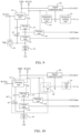
- FIG. 13 illustrates an equivalent schematic diagram of a pixel driving circuit in an exemplary embodiment of the present disclosure.
- the charging unit 41 may include a first transistor T 1 and a second transistor T 2 ;
- the storage unit 42 may include a storage capacitor C 1 ;
- the writing unit 44 may include a third transistor T 3 ;
- the driving unit 43 may include a fourth transistor T 4 ;
- the control unit 45 may include a fifth transistor T 5 ;
- the resetting unit 90 may include a sixth transistor T 6 ;
- the light-emitting unit 50 may include a light-emitting device OLED;
- the ultrasonic driving unit 60 may include a seventh transistor T 7 ;
- the signal acquisition unit 80 may include an eighth transistor T 8 and a ninth transistor T 9 .
- the control electrode of the first transistor T 1 is connected with the second signal terminal SCAN 2 , the first electrode of the first transistor T 1 is connected with the first power supply terminal VDD, and the second electrode of the first transistor T 1 is connected with the fourth node D.
- the control electrode of the second transistor T 2 is connected with the first signal terminal SCAN 1 , the first electrode of the second transistor T 2 is connected with the fourth node D, and the second electrode of the second transistor T 2 is connected with the second node A.
- the first electrode plate of the storage capacitor C 1 is connected with the second node A, and the second electrode plate of the storage capacitor C 1 is connected with the first electrode of the light-emitting device OLED.
- the control electrode of the third transistor T 3 is connected with the second signal terminal SCAN 2 , the first electrode of the third transistor T 3 is connected with the data input terminal Vdata, and the second electrode of the third transistor T 3 is connected with the third node C.
- the control electrode of the fourth transistor T 4 is connected to the second node A, the first electrode of the fourth transistor T 4 is connected to the fourth node D, and the second electrode of the fourth transistor T 4 is connected to the third node C.
- the control electrode of the fifth transistor T 5 is connected with the first signal terminal SCAN 1 , the first electrode of the fifth transistor T 5 is connected with the third node C, and the second electrode of the fifth transistor T 5 is connected with the first electrode of the light-emitting device OLED.
- the second electrode of the light-emitting device OLED is connected with the second power supply terminal VSS.
- the control electrode of the sixth transistor T 6 is connected with the first signal terminal SCAN 1 , the first electrode is connected with the fourth power supply terminal Vint, and the second electrode is connected with the first electrode of the light-emitting device OLED.
- the second electrode of the light-emitting device OLED is connected with the second power supply terminal VSS.
- the control electrode and the first electrode of the seventh transistor T 7 are connected with the second signal terminal SCAN 2 , and the second electrode is connected with the first node B.
- the first electrode of the ultrasonic sensing unit 70 is connected with the first node B, and the second electrode of the ultrasonic sensing unit 70 is connected with the third power supply terminal Tx.
- the control electrode of the eighth transistor T 8 is connected with the first node B, the first electrode of the eighth transistor T 8 is connected with the first power supply terminal VDD, and the second electrode of the eighth transistor T 8 is connected with the first electrode of the ninth transistor T 9 .
- the control electrode of the ninth transistor T 9 is connected with the first signal terminal SCAN 1 , the first electrode of the ninth transistor T 9 is connected with the second electrode of the eighth transistor T 8 , and the second electrode of the ninth transistor T 9 is connected with the output terminal OUT.
- transistors T 1 , T 5 and T 7 may all be P-type thin film transistors, and transistors T 2 , T 3 , T 4 , T 6 , T 8 and T 9 may all be N-type thin film transistors.
- the transistors used in all embodiments of the present disclosure may be thin film transistors or field effect transistors or other devices with the same characteristics.
- the thin film transistors may be oxide semiconductor thin film transistors, low-temperature polysilicon thin film transistors, amorphous silicon thin film transistors or microcrystalline silicon thin film transistors.
- all transistors in the embodiments of the present disclosure may be low-temperature polysilicon thin film transistors.
- the thin film transistors may be thin film transistors with a bottom gate structure or thin film transistor with a top gate structure, as long as the switching function can be realized.
- a working process of the pixel driving circuit in the embodiment of the present disclosure illustrated in FIG. 13 will be briefly introduced below in combination with the circuit timing diagram. Description will be made by taking transistors T 1 , T 5 and T 7 being P-type thin film transistors, and transistors T 2 , T 3 , T 4 , T 6 , T 8 and T 9 being N-type thin film transistors as an example.
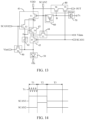
- FIG. 14 illustrates a timing diagram of a pixel driving circuit in an exemplary embodiment of the present disclosure.
- the pixel driving circuit may include three stages, namely, a first stage T 1 , a second stage T 2 and a third stage T 3 .
- the first stage T 1 may be called a pixel charging and ultrasonic transmission stage
- the second stage T 2 may be called a writing compensation and echo acquisition stage
- the third stage T 3 may be called a pixel luminescence stage.
- the first power supply terminal VDD provides a continuous high-level signal
- the second power supply terminal VSS provides a continuous low-level signal
- the fourth power supply terminal Vint provides a resetting voltage signal.
- FIG. 15 illustrates a schematic diagram of a state of a pixel driving circuit in the first stage in an exemplary embodiment of the present disclosure.
- the sixth transistor T 6 provides the resetting voltage signal of the fourth power supply terminal Vint to the first electrode of the light-emitting device OLED and the second electrode plate (i.e., lower electrode plate) of the storage capacitor C 1 , and the light-emitting device OLED does not emit light.
- the first transistor T 1 and the second transistor T 2 are on, and the charging unit 41 provides the high-level signal of the first power supply terminal VDD to the second node A through the fourth node D to charge the storage capacitor C 1 .
- the voltage of the second node A continuously increases with the increase of the charging time.
- FIG. 15 illustrates a state when the fourth transistor T 4 is off.
- the third transistor T 3 is off under the low-level signal of the second signal terminal SCAN 2
- the fifth transistor T 5 is off under the high-level signal of the first signal terminal SCAN 1 .
- the second signal terminal SCAN 2 is at a low level
- the seventh transistor T 7 is on to provide the low-level signal of the second signal terminal SCAN 2 to the first node B
- the signal of the first node B is a low-level signal.
- Tx is an alternating voltage
- the ultrasonic sensing unit 70 transmits ultrasonic waves outwards under the control of the first node B and the third power supply terminal Tx.
- the signal of the first node B is a low-level signal and the eighth transistor T 8 is off; the signal of the first signal terminal SCAN 1 is a high-level signal and the ninth transistor T 9 is on, but the output terminal OUT does not output a signal since the eighth transistor T 8 is off.
- FIG. 16 illustrates a schematic diagram of a state of a pixel driving circuit in a second stage in an exemplary embodiment of the present disclosure.
- the first transistor T 1 is off and the fifth transistor T 5 is off.
- the third transistor T 3 is on and provides the data signal of the data input terminal Vdata to the third node C.
- the voltage of the second node A reaches the threshold voltage Vth
- the fourth transistor T 4 is on, and the data signal of the third node C is provided to the second node A to compensate the voltage of the second node A to increase the voltage of the second node A to Vth+Vdata.
- the seventh transistor T 7 is off and the ninth transistor T 9 is on.
- Tx is a continuous stable voltage.
- the ultrasonic sensing unit 70 receives the reflected ultrasonic echoes and generates an induced voltage at the first node B.
- the eighth transistor T 8 is on.
- the induced voltage of the first node B can control the on degree of the eighth transistor T 8 , so that the eighth transistor T 8 outputs a second induced signal to the output terminal OUT.
- FIG. 17 illustrates a schematic diagram of a state of a pixel driving circuit in a third stage in an exemplary embodiment of the present disclosure.
- the second transistor T 2 and the sixth transistor T 6 are off.
- the third transistor T 3 is off.
- the first transistor T 1 is on, the fourth transistor T 4 is on, and the fifth transistor T 5 is on.
- the first power supply terminal VDD and the second power supply terminal VSS are on through the first transistor T 1 , the fourth transistor T 4 , the fifth transistor T 5 and the light-emitting device OLED to drive the light-emitting device OLED to emit light.
- Vs the voltage of the second electrode (the electrode connected to the third node C) of the fourth transistor T 4 is equal to Vint.
- the current flowing through the light-emitting device OLED may be:
- I W*C*u/(2*L)*(Vdata-Vint) ⁇ circumflex over ( ) ⁇ 2, where W/L is a width-to-length ratio of an active layer of the fourth transistor T 4 , C is a gate oxide capacitance per unit area, and u is a mobility of the fourth transistor T 4 .
- the seventh transistor T 7 is on and provides the low-level signal of the second signal terminal SCAN 2 to the first node B.
- the first node B is at a low level, so that the eighth transistor T 8 is off. Since the third power supply terminal Tx is a continuous stable voltage, the ultrasonic sensing unit 70 will not transmit ultrasonic waves outwards.
- the ninth transistor T 9 is off.
- the pixel driving circuit After the third stage T 3 , the pixel driving circuit maintains the state in the third stage T 3 until arrival of the next first stage T 1 .
- FIG. 18 illustrates a schematic diagram of a driving method of a pixel driving circuit in an exemplary embodiment of the present disclosure.
- the present disclosure further provides a driving method of a pixel driving circuit, which may be applied to the pixel driving circuit described above.
- the pixel driving circuit may include three stages, namely, a first stage T 1 , a second stage T 2 and a third stage T 3 .
- the first stage T 1 may be called a pixel charging and ultrasonic transmission stage
- the second stage T 2 may be called a writing compensation and echo acquisition stage
- the third stage T 3 may be called a pixel luminescence stage.
- a signal of the first power supply terminal VDD is provided to the second node A
- a signal of the second signal terminal SCAN 2 is provided to the first node B
- the ultrasonic sensing unit transmits ultrasonic waves.
- this act may include the following operations: under the control of the first signal terminal SCAN 1 and the second signal terminal SCAN 2 , the charging unit 41 provides the signal of the first power supply terminal to the second node A through the fourth node D to charge the storage unit 42 ; under the control of the second signal terminal SCAN 2 , the ultrasonic driving unit 60 provides the signal of the second signal terminal SCAN 2 to the first node B, and the ultrasonic sensing unit transmits ultrasonic waves according to the signals of the first node B and the third power supply terminal Tx.
- a signal of the data input terminal Vdata is provided to the third node C to compensate a voltage of the second node A; the reflected ultrasonic echoes are received and a first induction signal is generated at the first node B; under the control of the first induction signal of the first node B, a second induction signal is output to the output terminal.
- this act may include the following operations: under the control of the second signal terminal SCAN 2 , the writing unit 44 provides the signal of the data input terminal Vdata to the third node C (that is, writes a data voltage to the third node C) to compensate the voltage of the second node A; the ultrasonic sensing unit receives the reflected ultrasonic echoes and generates an induced voltage at the first node B, and the signal acquisition unit 80 outputs a second induced signal to the output terminal OUT under the control of the induced voltage at the first node B.
- the first power supply terminal VDD and the second power supply terminal VSS are on through the charging unit, the driving unit, the control unit and the light-emitting unit.
- this act may include the following operations: under the control of the second signal terminal SCAN 2 and the first signal terminal SCAN 1 , the first transistor T 1 in the charging unit 41 is on, the second transistor T 2 is off, and the first power supply terminal VDD and the fourth node D are on; under the control of the second node A, the control unit 43 is on, so that the fourth node D and the third node C are on; under the control of the first signal terminal SCAN 1 , the control unit 45 is on, so that the third node C and the first electrode of the light-emitting unit 50 are on.
- the first power supply terminal VDD and the second power supply terminal VSS are on through the charging unit, the driving unit, the control unit and the light-emitting unit to drive the light-emitting unit to emit light.
- the driving method may further include the following act: in the first stage T 1 , the signal of the fourth power supply terminal Vint is provided to the first electrode of the light-emitting unit.
- this act may include the following operations: under the control of the first signal terminal SCAN 1 , the resetting unit 90 provides the signal of the fourth power terminal Vint to the first electrode of the light-emitting unit 50 to reset the first electrode of the light-emitting unit 50 .
- the present disclosure further provides a display panel, which includes a plurality of the pixel driving circuits described above.
- the display panel may be any product or component having a display function, such as an OLED display panel, a mobile phone, a tablet computer, a television, a display, a notebook computer, a digital photo frame, a navigator.
- a display function such as an OLED display panel, a mobile phone, a tablet computer, a television, a display, a notebook computer, a digital photo frame, a navigator.
Landscapes
- Engineering & Computer Science (AREA)
- Physics & Mathematics (AREA)
- General Physics & Mathematics (AREA)
- Theoretical Computer Science (AREA)
- Computer Hardware Design (AREA)
- Human Computer Interaction (AREA)
- Multimedia (AREA)
- Control Of Indicators Other Than Cathode Ray Tubes (AREA)
- Electroluminescent Light Sources (AREA)
- Control Of El Displays (AREA)
Abstract
Description
I=W*C*u/(2*L)*(Vgs−Vth){circumflex over ( )}2
Vgs=Vg−Vs=Vdata+Vth−V int
Claims (15)
Applications Claiming Priority (3)
| Application Number | Priority Date | Filing Date | Title |
|---|---|---|---|
| CN202010325461.1 | 2020-04-23 | ||
| CN202010325461.1A CN111508413B (en) | 2020-04-23 | 2020-04-23 | Pixel driving circuit, driving method thereof and display panel |
| PCT/CN2021/077574 WO2021212996A1 (en) | 2020-04-23 | 2021-02-24 | Pixel driving circuit, driving method therefor, and display panel |
Publications (2)
| Publication Number | Publication Date |
|---|---|
| US20220309821A1 US20220309821A1 (en) | 2022-09-29 |
| US11651614B2 true US11651614B2 (en) | 2023-05-16 |
Family
ID=71877975
Family Applications (1)
| Application Number | Title | Priority Date | Filing Date |
|---|---|---|---|
| US17/431,437 Active 2041-05-20 US11651614B2 (en) | 2020-04-23 | 2021-02-24 | Pixel driving circuit, driving method thereof and display panel |
Country Status (3)
| Country | Link |
|---|---|
| US (1) | US11651614B2 (en) |
| CN (1) | CN111508413B (en) |
| WO (1) | WO2021212996A1 (en) |
Families Citing this family (2)
| Publication number | Priority date | Publication date | Assignee | Title |
|---|---|---|---|---|
| CN111508413B (en) * | 2020-04-23 | 2021-12-21 | 京东方科技集团股份有限公司 | Pixel driving circuit, driving method thereof and display panel |
| CN111968575B (en) * | 2020-09-07 | 2022-10-11 | 京东方科技集团股份有限公司 | Pixel driving circuit, driving method thereof and display device |
Citations (10)
| Publication number | Priority date | Publication date | Assignee | Title |
|---|---|---|---|---|
| CN108682386A (en) | 2018-05-14 | 2018-10-19 | 京东方科技集团股份有限公司 | A kind of pixel circuit and display panel |
| CN108806587A (en) | 2018-06-26 | 2018-11-13 | 京东方科技集团股份有限公司 | Pixel-driving circuit, In-cell touch panel, display device and driving method |
| CN208521297U (en) | 2018-06-21 | 2019-02-19 | 成都安瑞芯科技有限公司 | Ultrasonic wave identification circuit and fingerprint Identification sensor |
| WO2019055215A2 (en) | 2017-09-14 | 2019-03-21 | Qualcomm Incorporated | Ultrasonic transducer pixel readout circuitry and methods for ultrasonic phase imaging |
| CN109872683A (en) | 2019-03-28 | 2019-06-11 | 京东方科技集团股份有限公司 | A kind of pixel circuit, display panel and driving method |
| US20190197281A1 (en) | 2017-12-27 | 2019-06-27 | Lg Display Co., Ltd. | Fingerprint Sensing Display Apparatus |
| CN110008939A (en) | 2019-05-17 | 2019-07-12 | 京东方科技集团股份有限公司 | Fingerprint recognition pixel-driving circuit and its driving method, display panel |
| CN110214350A (en) | 2019-04-25 | 2019-09-06 | 京东方科技集团股份有限公司 | Driving circuit, array substrate, display device and driving method |
| CN110767161A (en) | 2019-11-08 | 2020-02-07 | 京东方科技集团股份有限公司 | Pixel circuit, driving method thereof and display device |
| CN111508413A (en) | 2020-04-23 | 2020-08-07 | 京东方科技集团股份有限公司 | Pixel driving circuit and driving method thereof, and display panel |
-
2020
- 2020-04-23 CN CN202010325461.1A patent/CN111508413B/en active Active
-
2021
- 2021-02-24 WO PCT/CN2021/077574 patent/WO2021212996A1/en not_active Ceased
- 2021-02-24 US US17/431,437 patent/US11651614B2/en active Active
Patent Citations (13)
| Publication number | Priority date | Publication date | Assignee | Title |
|---|---|---|---|---|
| WO2019055215A2 (en) | 2017-09-14 | 2019-03-21 | Qualcomm Incorporated | Ultrasonic transducer pixel readout circuitry and methods for ultrasonic phase imaging |
| US20190197281A1 (en) | 2017-12-27 | 2019-06-27 | Lg Display Co., Ltd. | Fingerprint Sensing Display Apparatus |
| CN110058718A (en) | 2017-12-27 | 2019-07-26 | 乐金显示有限公司 | Fingerprint sensing shows equipment |
| CN108682386A (en) | 2018-05-14 | 2018-10-19 | 京东方科技集团股份有限公司 | A kind of pixel circuit and display panel |
| US20210366395A1 (en) | 2018-05-14 | 2021-11-25 | Boe Technology Group Co., Ltd. | Pixel circuit, display panel and driving method |
| CN208521297U (en) | 2018-06-21 | 2019-02-19 | 成都安瑞芯科技有限公司 | Ultrasonic wave identification circuit and fingerprint Identification sensor |
| CN108806587A (en) | 2018-06-26 | 2018-11-13 | 京东方科技集团股份有限公司 | Pixel-driving circuit, In-cell touch panel, display device and driving method |
| CN109872683A (en) | 2019-03-28 | 2019-06-11 | 京东方科技集团股份有限公司 | A kind of pixel circuit, display panel and driving method |
| US11151937B2 (en) | 2019-04-25 | 2021-10-19 | Chengdu Boe Optoelectronics Technology Co., Ltd. | Driving circuit, array substrate, display device and driving method |
| CN110214350A (en) | 2019-04-25 | 2019-09-06 | 京东方科技集团股份有限公司 | Driving circuit, array substrate, display device and driving method |
| CN110008939A (en) | 2019-05-17 | 2019-07-12 | 京东方科技集团股份有限公司 | Fingerprint recognition pixel-driving circuit and its driving method, display panel |
| CN110767161A (en) | 2019-11-08 | 2020-02-07 | 京东方科技集团股份有限公司 | Pixel circuit, driving method thereof and display device |
| CN111508413A (en) | 2020-04-23 | 2020-08-07 | 京东方科技集团股份有限公司 | Pixel driving circuit and driving method thereof, and display panel |
Non-Patent Citations (2)
| Title |
|---|
| International Search Report for PCT/CN2021/077574 dated Jun. 2, 2021. |
| Office Action dated Aug. 5, 2021 for Chinese Patent Application No. 202010325461.1 and English Translation. |
Also Published As
| Publication number | Publication date |
|---|---|
| WO2021212996A1 (en) | 2021-10-28 |
| US20220309821A1 (en) | 2022-09-29 |
| CN111508413B (en) | 2021-12-21 |
| CN111508413A (en) | 2020-08-07 |
Similar Documents
| Publication | Publication Date | Title |
|---|---|---|
| US11315491B2 (en) | Pixel circuit, display panel and driving method | |
| CN107220630B (en) | Display substrate, driving method thereof and display device | |
| CN108806587B (en) | Pixel driving circuit, in-cell touch screen, display device and driving method | |
| CN108646949B (en) | Photoelectric detection circuit and method, array substrate, display panel, fingerprint identification method | |
| US11157712B2 (en) | Fingerprint recognition driving circuit, fingerprint recognition module, touch screen, display device and fingerprint recognition driving method | |
| US20210335249A1 (en) | Pixel circuit, driving method thereof, and display apparatus | |
| US11238789B2 (en) | Pixel circuit having a data line for sensing threshold and mobility characteristics of the circuit | |
| CN109147693B (en) | LED display device with infrared identification | |
| US11651614B2 (en) | Pixel driving circuit, driving method thereof and display panel | |
| US20250182705A1 (en) | Display device | |
| US11263954B2 (en) | Pixel circuit including an ultrasonic recognition circuit, method for driving the same, and display panel | |
| CN116229882A (en) | An array substrate, its driving method, a display panel, and a display device | |
| CN111968575B (en) | Pixel driving circuit, driving method thereof and display device | |
| CN114863865B (en) | Pixel driving circuit and driving method thereof, and display panel | |
| US11151937B2 (en) | Driving circuit, array substrate, display device and driving method | |
| US12260810B1 (en) | Pixel driving circuit, driving method for pixel driving circuit, and display panel | |
| US20240153571A1 (en) | Shift register and method of driving the same, scan driving circuit and display apparatus | |
| US20250078726A1 (en) | Pixel Circuit, Driving Method Thereof, Display Substrate and Display Device | |
| CN223993086U (en) | Detection device, display panel and display device | |
| WO2025123382A1 (en) | Display panel and display apparatus | |
| KR20250028960A (en) | Scan driver and display device including the same |
Legal Events
| Date | Code | Title | Description |
|---|---|---|---|
| FEPP | Fee payment procedure |
Free format text: ENTITY STATUS SET TO UNDISCOUNTED (ORIGINAL EVENT CODE: BIG.); ENTITY STATUS OF PATENT OWNER: LARGE ENTITY |
|
| AS | Assignment |
Owner name: BOE TECHNOLOGY GROUP CO., LTD., CHINA Free format text: ASSIGNMENT OF ASSIGNORS INTEREST;ASSIGNORS:LIU, KE;SHI, LING;YU, YANG;AND OTHERS;REEL/FRAME:057407/0705 Effective date: 20210702 Owner name: CHENGDU BOE OPTOELECTRONICS TECHNOLOGY CO., LTD., CHINA Free format text: ASSIGNMENT OF ASSIGNORS INTEREST;ASSIGNORS:LIU, KE;SHI, LING;YU, YANG;AND OTHERS;REEL/FRAME:057407/0705 Effective date: 20210702 |
|
| STPP | Information on status: patent application and granting procedure in general |
Free format text: DOCKETED NEW CASE - READY FOR EXAMINATION |
|
| STCF | Information on status: patent grant |
Free format text: PATENTED CASE |