US11650301B2 - Serial interface for parameter transfer in an ultrasound device - Google Patents
Serial interface for parameter transfer in an ultrasound device Download PDFInfo
- Publication number
- US11650301B2 US11650301B2 US17/088,477 US202017088477A US11650301B2 US 11650301 B2 US11650301 B2 US 11650301B2 US 202017088477 A US202017088477 A US 202017088477A US 11650301 B2 US11650301 B2 US 11650301B2
- Authority
- US
- United States
- Prior art keywords
- control data
- circuitry
- serial
- semiconductor chip
- ultrasound probe
- Prior art date
- Legal status (The legal status is an assumption and is not a legal conclusion. Google has not performed a legal analysis and makes no representation as to the accuracy of the status listed.)
- Active, expires
Links
- 238000002604 ultrasonography Methods 0.000 title claims abstract description 100
- 238000012546 transfer Methods 0.000 title description 2
- 230000004044 response Effects 0.000 claims abstract description 16
- 238000000034 method Methods 0.000 claims description 26
- 239000004065 semiconductor Substances 0.000 claims description 21
- 238000006243 chemical reaction Methods 0.000 claims description 20
- 239000000523 sample Substances 0.000 claims description 20
- 230000005540 biological transmission Effects 0.000 claims description 6
- 230000002123 temporal effect Effects 0.000 claims description 4
- 238000010586 diagram Methods 0.000 description 14
- 239000000758 substrate Substances 0.000 description 11
- 230000008901 benefit Effects 0.000 description 5
- 238000012545 processing Methods 0.000 description 4
- 230000015572 biosynthetic process Effects 0.000 description 3
- 230000003750 conditioning effect Effects 0.000 description 3
- 230000001934 delay Effects 0.000 description 3
- 230000004075 alteration Effects 0.000 description 2
- 238000003491 array Methods 0.000 description 2
- 230000001747 exhibiting effect Effects 0.000 description 2
- 230000006870 function Effects 0.000 description 2
- 230000006872 improvement Effects 0.000 description 2
- 239000000463 material Substances 0.000 description 2
- 238000012986 modification Methods 0.000 description 2
- 230000004048 modification Effects 0.000 description 2
- XUIMIQQOPSSXEZ-UHFFFAOYSA-N Silicon Chemical compound [Si] XUIMIQQOPSSXEZ-UHFFFAOYSA-N 0.000 description 1
- 230000004931 aggregating effect Effects 0.000 description 1
- 230000000295 complement effect Effects 0.000 description 1
- 230000003247 decreasing effect Effects 0.000 description 1
- 230000003111 delayed effect Effects 0.000 description 1
- 238000013461 design Methods 0.000 description 1
- 230000000694 effects Effects 0.000 description 1
- 229910044991 metal oxide Inorganic materials 0.000 description 1
- 150000004706 metal oxides Chemical class 0.000 description 1
- 238000013021 overheating Methods 0.000 description 1
- 230000008569 process Effects 0.000 description 1
- 230000009467 reduction Effects 0.000 description 1
- 229910052710 silicon Inorganic materials 0.000 description 1
- 239000010703 silicon Substances 0.000 description 1
- 230000001960 triggered effect Effects 0.000 description 1
Images


Classifications
-
- B—PERFORMING OPERATIONS; TRANSPORTING
- B06—GENERATING OR TRANSMITTING MECHANICAL VIBRATIONS IN GENERAL
- B06B—METHODS OR APPARATUS FOR GENERATING OR TRANSMITTING MECHANICAL VIBRATIONS OF INFRASONIC, SONIC, OR ULTRASONIC FREQUENCY, e.g. FOR PERFORMING MECHANICAL WORK IN GENERAL
- B06B1/00—Methods or apparatus for generating mechanical vibrations of infrasonic, sonic, or ultrasonic frequency
- B06B1/02—Methods or apparatus for generating mechanical vibrations of infrasonic, sonic, or ultrasonic frequency making use of electrical energy
- B06B1/0207—Driving circuits
- B06B1/0215—Driving circuits for generating pulses, e.g. bursts of oscillations, envelopes
-
- G—PHYSICS
- G01—MEASURING; TESTING
- G01S—RADIO DIRECTION-FINDING; RADIO NAVIGATION; DETERMINING DISTANCE OR VELOCITY BY USE OF RADIO WAVES; LOCATING OR PRESENCE-DETECTING BY USE OF THE REFLECTION OR RERADIATION OF RADIO WAVES; ANALOGOUS ARRANGEMENTS USING OTHER WAVES
- G01S7/00—Details of systems according to groups G01S13/00, G01S15/00, G01S17/00
- G01S7/52—Details of systems according to groups G01S13/00, G01S15/00, G01S17/00 of systems according to group G01S15/00
- G01S7/523—Details of pulse systems
- G01S7/524—Transmitters
-
- G—PHYSICS
- G01—MEASURING; TESTING
- G01S—RADIO DIRECTION-FINDING; RADIO NAVIGATION; DETERMINING DISTANCE OR VELOCITY BY USE OF RADIO WAVES; LOCATING OR PRESENCE-DETECTING BY USE OF THE REFLECTION OR RERADIATION OF RADIO WAVES; ANALOGOUS ARRANGEMENTS USING OTHER WAVES
- G01S15/00—Systems using the reflection or reradiation of acoustic waves, e.g. sonar systems
- G01S15/88—Sonar systems specially adapted for specific applications
- G01S15/89—Sonar systems specially adapted for specific applications for mapping or imaging
- G01S15/8906—Short-range imaging systems; Acoustic microscope systems using pulse-echo techniques
- G01S15/8909—Short-range imaging systems; Acoustic microscope systems using pulse-echo techniques using a static transducer configuration
- G01S15/8915—Short-range imaging systems; Acoustic microscope systems using pulse-echo techniques using a static transducer configuration using a transducer array
- G01S15/8927—Short-range imaging systems; Acoustic microscope systems using pulse-echo techniques using a static transducer configuration using a transducer array using simultaneously or sequentially two or more subarrays or subapertures
-
- G—PHYSICS
- G01—MEASURING; TESTING
- G01S—RADIO DIRECTION-FINDING; RADIO NAVIGATION; DETERMINING DISTANCE OR VELOCITY BY USE OF RADIO WAVES; LOCATING OR PRESENCE-DETECTING BY USE OF THE REFLECTION OR RERADIATION OF RADIO WAVES; ANALOGOUS ARRANGEMENTS USING OTHER WAVES
- G01S7/00—Details of systems according to groups G01S13/00, G01S15/00, G01S17/00
- G01S7/52—Details of systems according to groups G01S13/00, G01S15/00, G01S17/00 of systems according to group G01S15/00
- G01S7/52017—Details of systems according to groups G01S13/00, G01S15/00, G01S17/00 of systems according to group G01S15/00 particularly adapted to short-range imaging
- G01S7/52019—Details of transmitters
- G01S7/5202—Details of transmitters for pulse systems
-
- G—PHYSICS
- G01—MEASURING; TESTING
- G01S—RADIO DIRECTION-FINDING; RADIO NAVIGATION; DETERMINING DISTANCE OR VELOCITY BY USE OF RADIO WAVES; LOCATING OR PRESENCE-DETECTING BY USE OF THE REFLECTION OR RERADIATION OF RADIO WAVES; ANALOGOUS ARRANGEMENTS USING OTHER WAVES
- G01S7/00—Details of systems according to groups G01S13/00, G01S15/00, G01S17/00
- G01S7/52—Details of systems according to groups G01S13/00, G01S15/00, G01S17/00 of systems according to group G01S15/00
- G01S7/52017—Details of systems according to groups G01S13/00, G01S15/00, G01S17/00 of systems according to group G01S15/00 particularly adapted to short-range imaging
- G01S7/52023—Details of receivers
- G01S7/52034—Data rate converters
-
- G—PHYSICS
- G01—MEASURING; TESTING
- G01S—RADIO DIRECTION-FINDING; RADIO NAVIGATION; DETERMINING DISTANCE OR VELOCITY BY USE OF RADIO WAVES; LOCATING OR PRESENCE-DETECTING BY USE OF THE REFLECTION OR RERADIATION OF RADIO WAVES; ANALOGOUS ARRANGEMENTS USING OTHER WAVES
- G01S7/00—Details of systems according to groups G01S13/00, G01S15/00, G01S17/00
- G01S7/52—Details of systems according to groups G01S13/00, G01S15/00, G01S17/00 of systems according to group G01S15/00
- G01S7/52017—Details of systems according to groups G01S13/00, G01S15/00, G01S17/00 of systems according to group G01S15/00 particularly adapted to short-range imaging
- G01S7/52079—Constructional features
- G01S7/5208—Constructional features with integration of processing functions inside probe or scanhead
-
- G—PHYSICS
- G01—MEASURING; TESTING
- G01S—RADIO DIRECTION-FINDING; RADIO NAVIGATION; DETERMINING DISTANCE OR VELOCITY BY USE OF RADIO WAVES; LOCATING OR PRESENCE-DETECTING BY USE OF THE REFLECTION OR RERADIATION OF RADIO WAVES; ANALOGOUS ARRANGEMENTS USING OTHER WAVES
- G01S7/00—Details of systems according to groups G01S13/00, G01S15/00, G01S17/00
- G01S7/52—Details of systems according to groups G01S13/00, G01S15/00, G01S17/00 of systems according to group G01S15/00
- G01S7/52017—Details of systems according to groups G01S13/00, G01S15/00, G01S17/00 of systems according to group G01S15/00 particularly adapted to short-range imaging
- G01S7/52096—Details of systems according to groups G01S13/00, G01S15/00, G01S17/00 of systems according to group G01S15/00 particularly adapted to short-range imaging related to power management, e.g. saving power or prolonging life of electronic components
Definitions
- the present application relates to transmit generators in ultrasound devices, and related methods and apparatus.
- Some ultrasound devices include a waveform generator which provides electric waveforms to a pulser.
- the pulser controls an ultrasonic transducer to emit ultrasound acoustic waves.
- a method comprising performing parallel-to-serial conversion followed by serial-to-parallel conversion of ultrasound waveform generation control data.
- a method of controlling a plurality of pulsers coupled to a plurality of ultrasonic transducers comprising: with transmit circuitry, transmitting a serial stream of control data packets specifying operation of the plurality of pulsers to create a plurality of waveform segments of a plurality of multi-level waveforms; with decoding circuitry, performing a serial-to-parallel conversion by receiving the serial stream of the control data packets and transmitting the control data packets to the plurality of pulsers in parallel; and with the plurality of pulsers, generating a plurality of pulses based on the serial stream of the control data packets.
- an apparatus comprising: a plurality of ultrasonic transducers; a plurality of pulsers coupled to the plurality of ultrasonic transducers; transmit circuitry coupled to the plurality of pulsers and configured to provide to a first pulser of the plurality of pulsers a serial stream of control data packets specifying operation of the first pulser to create a plurality of waveform segments of a multi-level waveform; and decoding circuitry configured to perform a serial-to-parallel conversion by receiving the serial stream of the control data packets and transmitting the control data packets to the plurality of pulsers in parallel.
- FIG. 1 A illustrates schematically a block diagram of an ultrasound device comprising a plurality of pulsing circuits and a plurality of decoding circuits, according to a non-limiting embodiment of the present application.
- FIG. 1 B illustrates a circuit diagram of a pulsing circuit comprising two transistors, according to one aspect of the present application.
- FIG. 1 C illustrates schematically a block diagram of an ultrasound device comprising a waveform generator, according to some non-limiting embodiments.
- FIG. 2 A shows an illustrative arrangement of a transducer array, according to a non-limiting embodiment of the present application.
- FIG. 2 B illustrates schematically a block diagram of a waveform generator comprising a a plurality of packet generators, according to a non-limiting embodiment of the present application.
- FIG. 2 C illustrates schematically a block diagram of an ultrasound device comprising a plurality of decoding circuits, according to a non-limiting embodiment of the present application.
- FIG. 3 A illustrates a data path diagram showing a succession of packets, according to a non-limiting embodiment of the present application.
- FIG. 3 B illustrates a time diagram showing an exemplary multi-level pulse formed through a succession of packets, according to a non-limiting embodiment of the present application.
- FIG. 4 illustrates a method of controlling a plurality of pulsers coupled to a plurality of ultrasonic transducers, according to a non-limiting embodiment of the present application.
- An ultrasound probe may include integrated circuitry for generating waveforms emitted by the probe.
- the integrated circuitry may be fabricated on a complementary metal oxide semiconductor (CMOS) die, also referred to herein as a “chip.”
- CMOS complementary metal oxide semiconductor
- ultrasonic transducers may be integrated with the CMOS chip, thus forming an ultrasound-on-a-chip device.
- the ultrasonic transducers may be capacitive micromachined ultrasonic transducers (CMUTs), which may be integrated with the integrated circuitry on the CMOS die.
- the integrated circuitry may include waveform generation circuitry configured to produce the electric waveforms which drive the ultrasonic transducers.
- the generation of such multi-level pulses may require complicated driving circuitry to control the state of the pulsing circuits.
- the complexity of the driving circuitry may be further exacerbated when the generation of the multi-level pulses occurs asynchronously.
- the complexity of the driving circuitry translates into sizable power and space requirements. This may be impractical when the ultrasound device is to be disposed in a handheld ultrasound probe, stethoscope, or other compact form, in which the available power may be limited (e.g., to the power that can be supplied by batteries) or the power consumption kept below some threshold to prevent overheating or unsafe operation, and the real estate may be limited to a few cubic centimeters.
- multi-level pulses may be generated using software-defined waveform generators.
- Software-defined waveform generators of the type described herein may significantly reduce the power and space requirements of the waveform generator(s) by limiting the amount of hardware used to perform pulse generation.
- the waveform generator may have access to a memory storing templates, such that each template represents a specific state for the pulsing circuits.
- the templates may contain a set of selectable referenced voltages that a pulsing circuit can lock to.
- the templates may also be referred to herein as “master segments,” “waveform segments,” or by other similar terminology.
- the waveform generator may comprise a controller configured to access the templates stored in the memory, and packetize templates such that each packet may control one or more pulsing circuits to generate a pulse segments.
- Pulse segments will be referred to herein as pulse portions, such that the voltage of the pulse is constant throughout the duration of the pulse segment, and is locked to the selected reference voltage.
- master segments and packets are defined in the digital domain while pulse segments are defined in the analog domain.
- spatial apodization of ultrasound signals is achieved using circuitry which operates on a serial data stream input provided by a waveform generator, rather than parallel input data streams.
- decoding circuitry disposed along the packet data path between the waveform generator and the pulsing circuits of an ultrasound device may be configured to provide spatial apodization by receiving and spatially modulating the packets generated by the waveform generator based on a desired spatial profile. Accordingly, each ultrasonic transducer of the array may be provided with an input control value that depends on the location of the transducer.
- These features may facilitate formation of a power and space-efficient circuit for generating waveforms to control ultrasonic transducers, and thus may facilitate formation of an ultrasound-on-a-chip device including a CMOS substrate with integrated circuitry and ultrasonic transducers.
- pulsing circuits configured to provide multi-level pulses.
- the pulsing circuits may be configured to provide one or more pulses to a respective ultrasonic transducer of an ultrasound device.
- the pulse(s) may be formed by a succession of pulse segments. Each pulse segment of the pulse may assume one among a set of selectable reference voltages, between an initial time t i and a final t f .
- the pulses may be asynchronous in some embodiments, such that the duration t f -t i of each pulse segment may be variable.
- FIG. 1 A illustrates schematically a block diagram of an ultrasound device comprising a plurality of pulsing circuits and a plurality of decoding circuits, according to a non-limiting embodiment of the present application.
- Ultrasound device 100 may comprise a plurality of circuitry channels 102 1 . . . 102 N , where N is an integer. Circuitry channels 102 1 . . . 102 N may be electrically connected to respective ultrasonic transducers 101 1 . . . 101 N .
- Ultrasound device 100 may further comprise analog-to-digital converter (ADC) 111 .
- ADC analog-to-digital converter
- the circuitry channels 102 1 . . . 102 N may comprise circuitry for the transmission and/or reception of ultrasound acoustic waves.
- circuitry channels 102 1 . . . 102 N may comprise decoding circuits 105 1 . . . 105 N Coupled to respective pulsing circuits 103 1 . . . 103 N .
- the pulsing circuits 103 1 . . . 103 N may control respective ultrasonic transducers 101 1 . . . 101 N to emit acoustic waveforms.
- Pulsing circuits 103 1 . . . 103 N are circuits, in some embodiments, configured to provide pulses to respective ultrasonic transducers 101 1 . . . 101 N .
- pulsing circuits 103 1 . . . 103 N may provide multi-level pulses exhibiting three or more levels selected from a set of selectable levels.
- the selectable levels may be reference voltages in some embodiments.
- the pulsing circuits may be configured to receive one reference voltage at a time and to form pulses that lock to the received reference voltage.
- the pulsers may provide bipolar pulses capable of exhibiting positive and/or negative voltages.
- pulsing circuits 103 1 . . . 103 N may comprise two transistors.
- FIG. 1 B illustrates a circuit diagram of a pulsing circuit 103 which may serve as any of the pulsing circuits 103 1 . . . 103 N of FIG. 1 A .
- the pulsing circuit 103 of FIG. 1 B comprising a first transistor 127 and a second transistor 129 .
- transistor 127 is a positive metal-oxide-semiconductor (pMOS) transistor and transistor 129 is a negative metal-oxide-semiconductor (nMOS) transistor.
- pMOS positive metal-oxide-semiconductor
- nMOS negative metal-oxide-semiconductor
- any other suitable number and/or type of transistor may be used.
- Transistor 127 may be set to a conductive state through control signal V c1 when a new reference voltage, greater than the previously selected reference voltage, is selected. In this case, transistor 127 may drive an electric current between supply voltage V H and ultrasonic transducer 101 and the voltage across the terminals of the ultrasonic transducer may be increased until the currently selected reference voltage is reached.
- a feedback circuit 125 may compare the voltage across the terminals of the ultrasonic transducer and compare it to the currently selected reference voltage. When the voltage across the terminals of the transducer is equal to the reference voltage, or alternatively, is equal to a voltage proportional to the reference voltage by a constant and predefined factor, feedback circuit 125 may turn off transistor 127 through control signal V c1 . Owing to the fact that ultrasonic transducer 101 is capacitive, the ultrasonic transducer may hold a voltage across its terminals that is equal or proportional to the reference voltage.
- transistor 129 may be set to a conductive state through control signal V c2 when a new reference voltage, less than the previously selected reference voltage, is selected.
- transistor 129 may drive an electric current between supply voltage V L and ultrasonic transducer 101 , and the voltage across the terminals of the ultrasonic transducer may be decreased until the currently selected reference voltage is reached.
- V L is less than V H .
- V L may be a positive voltage, a negative voltage, or zero.
- Feedback circuit 125 may compare the voltage across the terminals of the ultrasonic transducer to the currently selected reference voltage.
- feedback circuit 125 may turn off transistor 129 through control signal V c2 . Owing to the fact that ultrasonic transducer 101 is capacitive, the transducer may hold a voltage across its terminals that is equal or proportional to the reference voltage.
- decoding circuits suitable for use in an ultrasound device having a plurality of multi-level pulsers An example relates to decoding circuits 105 1 . . . 105 N of FIG. 1 A .
- decoding circuits 105 1 . . . 105 N may be part of a single circuitry element, while in other embodiments, they may comprise separate circuits.
- each decoding circuit may correspond to a respective ultrasonic transducer. However, in other embodiments, more than one ultrasonic transducer may share one decoding circuit.
- 105 N may be configured to modulate the packets, as described further below, generated by a waveform generator and to provide the modulated packets to respective pulsing circuits 103 1 . . . 103 N .
- decoding circuits 105 1 . . . 105 N may provide pulses to respective pulsing circuits 103 1 . . . 103 N such that spatial apodization is obtained.
- ultrasound device 100 may further comprise one or more waveform generators (not shown in FIG. 1 A ) configured to provide serialized packets to decoding circuits 105 1 . . . 105 N .
- the waveform generator(s) may be configured to form packets by aggregating master segments selectable from a library of selectable master segments.
- the receive circuitry of the circuitry channels 102 1 . . . 102 N may receive the electrical signals from respective ultrasonic transducers 101 1 . . . 101 N in response to receiving an ultrasound acoustic wave.
- each circuitry channel 102 1 . . . 102 N comprises a respective receive switch 107 1 . . . 107 N and a receiving circuit 109 1 . . . 109 N .
- the receive switches 107 1 . . . 107 N may be controlled to activate/deactivate readout of an electrical signal from a given ultrasonic transducer 101 1 . . . 101 N .
- the receiving circuits 109 1 . . . 109 N may comprise trans-impedance amplifiers (TIAs).
- Ultrasound device 100 may further comprise ADC 111 .
- ADC 111 may be configured to digitize the signals received by ultrasonic transducers 101 1 . . . 101 N . The digitization of the various received signals may be performed in series or in parallel.
- FIG. 1 A illustrates a number of components as part of a circuit of an ultrasound device, it should be appreciated that the various aspects described herein are not limited to the exact components or configuration of components illustrated.
- the ultrasonic transducers 101 1 . . . 101 N are sensors, in some embodiments, producing electrical signals representing received ultrasound acoustic waves.
- the ultrasonic transducers may also transmit ultrasound acoustic waves in some embodiments.
- the ultrasonic transducers may be capacitive micromachined ultrasonic transducers (CMUTs) in some embodiments. However, other types of capacitive ultrasonic transducers may be used in other embodiments.
- the components of FIG. 1 A may be located on a single substrate or on different substrates.
- the ultrasonic transducers 101 1 . . . 101 N may be on a first substrate and the remaining illustrated components may be on a second substrate.
- the first and/or second substrates may be semiconductor substrates, such as silicon substrates.
- the components of FIG. 1 A may be on a single substrate.
- the ultrasonic transducers 101 1 . . . 101 N and the illustrated circuitry may be monolithically integrated on the same semiconductor die.
- the components of FIG. 1 A form part of an ultrasound probe.
- the ultrasound probe may be handheld.
- the components of FIG. 1 A form part of an ultrasound patch configured to be worn by a patient.
- the ultrasound device may comprise one or more waveform generators configured to generate a plurality of packets based on a set of selectable templates.
- the packets may be decoded by decoding circuits 105 1 . . . 105 N and may be used to form multi-level pulses through pulsing circuits 103 1 . . . 103 N .
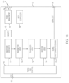
- FIG. 1 C illustrates schematically a block diagram of an ultrasound device 110 comprising a waveform generator 151 , according to some non-limiting embodiments.
- Ultrasound device 100 may further comprise memory 153 , transmitter array 150 , transducer array 152 , receiver array 154 , signal conditioning/processing circuit 170 , timing and control circuit 160 , power management circuit 180 , or any suitable combination thereof.
- ultrasound device 110 may comprise some or all of the components of ultrasound device 100 .
- Transmitter array 150 of ultrasound device 110 may comprise pulsing circuits 103 1 . . . 103 N and decoding circuits 105 1 . . . 105 N of ultrasound device 100 in some embodiments.
- Transducer array 152 may comprise ultrasonic transducers 101 1 . . . 101 N in some embodiments. The ultrasonic transducers may be organized in one-dimensional or two-dimensional arrays.
- Receiver array 154 may comprise receive switches 107 1 . . . 107 N and a receiving circuits 109 1 . . . 109 N in some embodiments.
- Signal conditioning/processing unit 170 may comprise ADC 111 . In some embodiments, signal conditioning/processing unit 170 may further comprise digital circuitry configured to form images based on the ultrasound acoustic waves received by transducer array 152 .
- waveform generator 151 may be configured to generate control signals to drive pulsing circuits 103 1 . . . 103 N of transmitter array 150 .
- the control signals may be organized in packets, such that each packet may comprise information corresponding to a selected reference voltage.
- the packets may be directed to respective feedback circuits 125 of pulsing circuits 103 1 . . . 103 N .
- the content of the packets will be described in connection with FIG. 3 A .
- waveform generator 151 may be connected to memory 153 .
- memory 153 may store a plurality of master segments.
- Waveform generator 151 may access memory 153 to obtain one or more master segments.
- Waveform generator 151 may combine various master segments to form a desired succession of packets.
- memory 153 may comprise random access memory (RAM) units, read-only memory (ROM) units, flash memory units, or any suitable type of memory that can store waveform segments.
- waveform generator 151 may comprise one or more logic circuits.
- the logic circuit(s) may comprise processors, field-programmable gate arrays (FPGAs), application-specific integrated circuits (ASICs), microcontrollers, or any suitable combination thereof.
- Waveform generator 151 may be configured to access data stored in memory 153 and to execute computer instruction(s) to process the data obtained from the memory.
- the ultrasound device 100 may further comprise an output port 114 which may be a physical interface between ultrasound device 100 and an external device.
- output port 114 may connect to external devices capable of receiving and processing large amounts of ultrasound data, such as a specialized FPGA, a GPU, or other suitable device. While only a single output port 114 is illustrated, it should be appreciated that multiple output ports may be provided.
- Ultrasound device 100 may also include a clock input port 116 to receive and provide a clock signal CLK to the timing and control circuit 160 .
- Power management circuit 180 may receive ground (GND) and voltage reference (V IN ) signals.
- a high-intensity focused ultrasound (HIFU) controller 190 may be included if ultrasound device 100 is to be used to provide HIFU.
- all of the illustrated elements may be formed on a single semiconductor die (or substrate or chip) 112 , though not all embodiments are limited in this respect.
- Transducer array 152 may be arranged in rows and columns in some embodiments.
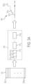
- FIG. 2 A shows an illustrative arrangement of a transducer array, according to a non-limiting embodiments of the present application.
- transducer array 152 of an ultrasound device 100 may have multiple modules 204 .
- a module 204 may comprise multiple elements 206 .
- An element 206 may comprise multiple cells 208 .
- a cell 208 may comprise an ultrasonic transducer of the type described in connection with FIG. 1 A .
- transducer array 152 comprises 144 modules arranged as an array having 72 rows and 2 columns.
- a transducer array may comprise any suitable number of modules (e.g., at least one module, at least two modules, at least ten modules, at least 100 modules, at least 1000 modules, at least 5000 modules, at least 10,000 modules, at least 25,000 modules, at least 50,000 modules, at least 100,000 modules, at least 250,000 modules, at least 500,000 modules, between two and a million modules, or any number of range of numbers within such ranges) that may be arranged as a one-dimensional or two-dimensional array of modules having any suitable number of rows and columns or in any other suitable way.
- modules e.g., at least one module, at least two modules, at least ten modules, at least 100 modules, at least 1000 modules, at least 5000 modules, at least 10,000 modules, at least 25,000 modules, at least 50,000 modules, at least 100,000 modules, at least 250,000 modules, at least 500,000 modules, between two and a million modules, or any number of range of numbers within such
- each module comprises 64 ultrasound elements arranged as an array having two rows and 32 columns.
- a module may comprise any suitable number of ultrasound elements (e.g., one element, at least two ultrasound elements, at least four ultrasound elements, at least eight ultrasound elements, at least 16 ultrasound elements, at least 32 ultrasound elements, at least 64 ultrasound elements, at least 128 ultrasound elements, at least 256 ultrasound elements, at least 512 ultrasound elements, between two and 1024 ultrasound elements, at least 2500 ultrasound elements, at least 5,000 ultrasound elements, at least 10,000 ultrasound elements, at least 20,000 ultrasound elements, between 1000 and 20,000 ultrasound elements, or any number of range of numbers within such ranges) that may be arranged as a one-dimensional or two-dimensional array of ultrasound elements having any suitable number of rows and columns or in any other suitable way.
- ultrasound elements e.g., one element, at least two ultrasound elements, at least four ultrasound elements, at least eight ultrasound elements, at least 16 ultrasound elements, at least 32 ultrasound elements, at least 64 ultrasound elements, at least 128 ultrasound elements, at least 256 ultrasound elements, at least 512 ultrasound
- each ultrasound element comprises 16 cells 208 arranged as a two-dimensional array having four rows and four columns, a cell representing an ultrasonic transducer and those two terms being used synonymously herein.
- an element may comprise any suitable number of cells (e.g., one, at least two, at least four, at least 16, at least 25, at least 36, at least 49, at least 64, at least 81, at least 100, between one and 200, or any number or range of numbers within such ranges) that may be arranged as a one-dimensional or two dimensional array having any suitable number of rows and columns (square or rectangular) or in any other suitable way.
- each cell 208 may comprise an ultrasonic transducer of the type described in connection with FIG. 1 A .
- transmitter array 150 may be arranged in a configuration that matches the modules, ultrasound elements and cells illustrated in FIG. 2 A , such that to each ultrasonic transducer correspond one pulsing circuit.
- a single pulsing circuit may be configured to drive a plurality of ultrasonic transducers, such as all the ultrasonic transducers of a cell 208 .
- the circuitry used to generate multi-level pulses may be reduced, in some instances significantly, by performing the generation of the pulses via software.
- a computer code may be programmed by a user to provide a desired pulse profile.
- the profile of the pulse may be engineered based on the nature of the target being probed and/or the environment in which the probing takes place.
- the computer code may comprise a set of instructions configured to interact with waveform generator 151 .
- waveform generator 151 may generate a plurality of packets of the type described above.
- waveform generator 151 may be configured to generate packets in a serialized fashion. Accordingly, each packet may be transmitted following the transmission of a preceding packet. However the application is not limited in this respect and packets may be transmitted using any suitable degree of parallelization.
- FIG. 2 B illustrates schematically a block diagram of a waveform generator, according to a non-limiting embodiments of the present application.
- Waveform generator 151 may comprise one or more packet generators (e.g., packet generators 260 1 and 260 2 ), one or more encoding circuits (e.g., encoding circuits 262 1 and 262 2 ), controller 265 and delay mesh circuit 269 .
- Memory 153 may comprise a plurality of records, such that a record, and in some embodiments each record, contains one master segment.
- the master segments collectively represent all the possible states that the pulsing circuits can assume.
- the master segments may comprise a field for the selectable reference voltages.
- the master segments may comprise a field for control signals V c1 and V c2 for respective feedback circuits 125 of pulsing circuits 103 1 . . . 103 N .
- memory 153 may be partitioned, and may comprise at least one section for each packet generator.
- packet generator 260 1 may use data stored in a section of memory 153 and packet generator 260 2 may use data stored in another section of memory 153 .
- such portions may overlap. In other embodiments, such portions may comprise the same portion.
- controller 265 may control a packet generator to access memory 153 and to select a number of master segments, as requested by the user.
- the packet generator may form a succession of packets based on the selected master segment. Each packet may correspond to a selected master segment.
- specific packets that do not have any corresponding master segment may be included in the packet stream by the packet generators. For example, the first packet of a succession of packets, or start_packet, may be generated by the packet generator before any other packet corresponding to a master segment. Additionally, or alternatively, the last packet of a succession of packets, or end_packet, may be generated by the packet generator after all other packets.
- waveform generator 151 may comprise two packet generators, such that each packet generator provides packets to a column comprising a plurality of ultrasound elements (such as ultrasound element 206 ).
- each packet generator provides packets to a column comprising a plurality of ultrasound elements (such as ultrasound element 206 ).
- the application is not limited in this respect and any other suitable number of packet generators may be used such that each packet generator may provide packets to any suitable number of elements.
- the packets generated by packet generators 260 1 and 260 2 may be provided to respective encoding circuits 262 1 and 262 2 .
- the encoding circuit may encode the packets provided.
- encoding circuit may be configured to perform serialization of the packets. The encoding circuit may reduce the amount of data used to provide packets generated by the packet generator to the pulsing circuits, and thus may provide a valuable reduction in the amount of memory used to store and communicate the desired packets.
- the encoding circuit may be configured to implement an N-to-M bit encoder (where each of N and M is a positive integer and where N is greater than M) so that when the encoding circuit encodes an input signal consisting of B bits the resultant encoded signal includes approximately B*M/N bits (where B is a positive integer).
- the encoding circuit may be configured to implement a 2-to-1 bit encoder so that when the encoding circuitry encodes an input signal of B bits, the resultant encoded signal has approximately B/2 bits.
- the encoding circuitry may be configured to implement a 3-to-2 bit encoder so that when the encoding circuitry encodes an input signal of B bits, the resultant encoded signal has approximately 2B/3 bits.
- the encoding circuitry may be configured to implement a 3-to-1 bit encoder so that when the encoding circuitry encodes an input signal of B bits, the resultant signal has approximately B/3 bits. More details of a non-limiting suitable encoding circuit may be found in U.S. Pat. No. 9,229,097, which is incorporated herein by reference in its entirety.
- the encoded packets generated by encoding circuits 262 1 and 262 2 may be provided to delay mesh circuit 269 in some embodiments.
- Delay mesh circuit 269 may include a delay mesh for producing multiple versions of the packets, the delay mesh having an input configured to receive the packets generated by the waveform generator and a plurality of (parallel) outputs configured to provide the multiple versions of the packets to the plurality of pulsing circuits.
- the delay mesh may be controlled to produce different versions of the packets generated by the waveform generator in response to different controls applied to the delay mesh. In this way, the ultrasound device can be controlled to generate different types of ultrasound waveforms.
- delay mesh circuit 269 may comprise a plurality of delay mesh units each of which may delay packets to obtain one or more time-delayed versions of the packets and provide them as output signals to one or more pulsing circuits. Output signals provided to one or more other delay mesh units may be further time-delayed by those delay mesh units and be transmitted and/or further processed by still other delay mesh units. In this way, a packet input to the delay mesh circuit may propagate through a plurality of delay mesh units, with one or more of the delay mesh units time-delaying the packet providing the resulting time-delayed version(s) to one or more ultrasound elements for transmission.
- delay mesh circuitry may generate multiple time-delayed versions of the packet and provide these versions the pulsing circuits.
- a delay mesh unit may comprise a buffer for storing and/or performing operations on a packet.
- delay mesh circuit 269 may comprise many delay mesh units and, as such, reducing the size of the buffer of each delay mesh unit may reduce both space and power requirements of implementing delay mesh circuitry on a single substrate ultrasound device. More details of a non-limiting suitable delay mesh circuit may be found in U.S. Pat. No. 9,229,097, which is incorporated herein by reference in its entirety.
- delay mesh circuit 269 may have a plurality of outputs 270 1 . . . 270 N .
- the number of output is equal to the number of pulsing circuits of transmitter array 150 .
- the various outputs 270 1 . . . 270 N may be different time-delayed versions of the packets provided by the encoding circuits in some embodiments. In other embodiments, the various outputs 270 1 . . . 270 N may all have equal delays.
- delay mesh circuit 269 may be configured to provide temporal apodization.
- transmitter array 150 may comprise a plurality of decoding circuits.
- the encoding circuits may decode the packets obtained through outputs 270 1 . . . 270 N .
- FIG. 2 C illustrates schematically a block diagram of an ultrasound device comprising a plurality of decoding circuits, according to a non-limiting embodiments of the present application.
- Each decoding circuit 105 1 . . . 105 N may receive one or more packets from respective outputs 270 1 . . . 270 N .
- Controller 266 may be configured to control the decoding circuits 105 1 . . . 105 N .
- Each decoding circuit may be connected to a respective pulsing circuit 103 1 . . . 103 N .
- Each pulsing circuit may be connected to a ultrasonic transducer 101 1 . . . 101 N .
- controller 266 may operate in response to the execution of a set of computer instructions.
- decoding the serialized packet may comprise performing a serial-to-parallel conversion.
- the decoding circuits may receive the packet one bit at a time, and may form one or more words of bits.
- one word may comprise the bits used to define a reference voltage.
- the word corresponding to the reference voltage may be transmitted in parallel by the encoding circuits to respective pulsing circuits. “Parallel transmission” will be referred to herein such that each bit forming a word is transmitted on a respective conductive wire.
- controller 266 may be configured to modulate the packets received.
- Modulation of a packet as used herein refers to the multiplication, or division, of the value of the packet corresponding to the selected reference voltage by a desired factor. The effect of modulating a packet is the generation of a scaled version of the reference voltage transmitted within the packet.
- the various packets received by the decoding circuits may be modulated with different factors. For example, the packets may be modulated according to a desired modulation profile, such that each decoding circuit may provide a desired factor.
- Packets may be modulated to provide spatial apodization across the array of ultrasonic transducers.
- the reference voltage contained in a packet may be modulated by dividing, or multiplying it by a factor that is between 0.001 and 1 in some embodiments, between 0.001 and 0.999 in some embodiments, between 0.01 and 0.99 in some embodiments, between 0.1 and 0.9 in some embodiments, between 0.25 and 0.75 in some embodiments, between 0.4 and 0.7 in some embodiments, or between any other suitable values or range of values. Other values are also possible.
- the modulation may be performed in the digital domain.
- the modulation factors may be represented by two bits, thus providing four combinations.
- the modulation factors may be equal to 0, 0.4, 0.7 and 1. Other values are also possible.
- the decoding circuits may be configured to perform spatial apodization, such that the emitted ultrasound acoustic wave has a main lobe in the middle of the array and the intensity decays toward the edges of the array.
- the decoding circuits may be configured to implement an M-to-N bit decoder (where each of N and M is a positive integer and where N is greater than M) so that when the decoding circuits decode an input signal of B bits the resultant decoded signal has approximately B*N/M bits (where B is a positive integer).
- a decoding circuit may be configured to implement a 1-to-2 bit decoder so that when the decoding circuitry decodes an input signal of B bits, the resultant decoded signal has approximately 2B bits.
- the decoding function may be the inverse of the encoding function provided by encoding circuits 262 1 and 262 2 .
- FIG. 3 A illustrates a data path diagram showing a succession of packets, according to a non-limiting embodiment of the present application.
- FIG. 3 A illustrates memory 153 comprising a plurality of records, such that each record contains a master segment 353 1 . . . 353 N .
- master segments 353 1 . . . 353 N collectively represent a base for the generation of desired pulse profiles.
- Stage 310 of the data path represents the generation of an non-limiting exemplary succession of packets 311 1 , 311 2 . . . 311 k where k may assume any integer value greater than two.
- Each packet may correspond to one of the master segments.
- the succession of packets may begin with a start_packet and/or may end with an end_packet.
- Packet 311 1 is shown in additional detail.
- packet 311 1 may comprise a field 312 A containing one or more bits to determine the conductive state of transistors 127 and 129 .
- Field 312 A may be directed to a feedback circuit 125 of a respective pulsing circuit. Based on field 312 A , the feedback circuit may control signals V c1 and V c2 .
- packet 311 1 may comprise a field 312 B containing one or more bits representing a reference voltage.
- the number of bits needed to represent the reference voltage may depend on the number of selectable reference voltages. As an example, if n is the number of selectable voltages, field 312 B may contain a number of bits that is greater than, less than, or equal to log 2 n.
- the number of bits used to represent field 312 B may be reconfigured during run-time. For example, the multi-level pulser may be reconfigured, during run-time, to operate as a 2-level pulser. In such circumstance, the number of bits representing the reference voltage may be reduced.
- Field 312 B may be directed to a feedback circuit 125 of a respective pulsing circuit.
- packet 311 1 may comprise a field 312 C containing one or more control bits.
- the control bits may be directed to delay mesh circuit 269 to determine the delays across output 270 1 . . . 270 N and/or to controller 266 to control the spatial apodization profile.
- Pulse 320 may comprise pulse segments 321 1 , 321 2 . . . 321 k , such that each pulse segment is generated in response to a respective packet 311 1 , 311 2 . . . 311 k .
- the duration of each pulse segment may be controlled by a counter configured to count clock cycles until a predetermined segment duration is reached.
- the pulse may be asynchronous in some embodiments, such that pulse segments may have different durations.
- the master segments and the packets may be defined in the digital domain while the pulse segments may be defined in the analog domain.
- FIG. 3 B illustrates a time diagram showing an exemplary multi-level pulse 301 formed through a succession of packets, according to a non-limiting embodiment of the present application.
- a reference voltage may be selected from among seven selectable reference voltages RV 1 . . . RV 7 .
- t 1 , t 2 , t 3 , t 4 , t 5 , t 6 , t 7 , t 8 , t 9 and t 10 a new reference voltage is selected.
- RV 4 is selected at t 1
- RV 5 is selected at t 2
- RV 6 is selected at t 3 , etc.
- An “event” is defined herein as the time at which a new reference voltage is selected, such as time t 1 , t 2 , t 3 , etc. While in the non-limiting example of FIG. 3 B a set of seven selectable reference voltages are provided, any suitable number of reference voltages may be employed. In some embodiments, the pulse may be bipolar and each selectable reference voltage can be positive and/or negative.
- the packet may comprise field PMOS/NMOS, serving as field 312 A .
- the pMOS transistor may be activated (ON state) to increase the voltage in response to the selection of a reference voltage that is greater than the reference voltage previously selected.
- the nMOS transistor may be activated (ON state) to decrease the voltage in response to the selection of a reference voltage that is less than the reference voltage previously selected.
- the packet may comprise field REF_V, serving as field 312 B to select a reference voltage, from the set of selectable reference voltage.
- REF_V may comprise three or more bits to produce eight or more combinations.
- a clock counter may count clock cycles until a duration associated with a packet is reached. In the embodiment shown in FIG. 3 B , the packets exhibit respective durations D 1 , D 2 , D 3 , D 4 , D 5 , D 6 , D 7 , D 8 , D 9 and D 10 defined by the field duration.
- FIG. 4 illustrates the steps of a method of controlling a plurality of pulsers coupled to a plurality of ultrasonic transducers, according to a non-limiting embodiment of the present application.
- Method 400 may begin at act 402 , in which waveform generator 151 may access memory 153 , and may obtain a master segment. This operation may be triggered by the execution of a computer code in some embodiments.
- the master segment may comprise values intended to define the characteristics of a corresponding pulse segment.
- the master segment may comprise a value representing a reference voltage of a plurality of selectable reference voltages.
- the corresponding pulse segment may have a voltage locked to the reference voltage.
- the master segment may comprise a value representing the conductive state of a first transistor, such as transistor 127 and/or the conductive state of a second transistor, such as transistor 129 . Based on such value, transistors 127 and 129 may be set to a conductive or a non-conductive state throughout the duration of the pulse segment corresponding to the master segment.
- waveform generator 151 may form a packet based on the master segment obtained from memory 153 at act 402 .
- the packet formed may comprise the one or more values defined in the master segment.
- the packet may comprise values that may be used to control the data path of the packet.
- the packet may comprise a value representing the duration of the pulse segment corresponding to the packet.
- the duration of a pulse segment may be defined through a counter configured to count clock cycles until the desired number of clock cycles is reached.
- the packet may be transmitted to decoding circuitry.
- the decoding circuitry may comprise decoding circuits 105 1 . . . 105 N in some embodiments.
- the packet may be transmitted serially.
- the packet may be transmitted one bit at a time.
- waveform generator 151 may comprise one or more packet generators, such as packet generators 260 1 and 260 2 , each of which may transmit a packet serially.
- waveform generator 151 may obtain a plurality of master segments from memory 153 , and may form a plurality of packets. In some embodiments, for each master segment obtained one packet is formed. In some embodiments, each packet may be used to define a pulse segment. Pulse segments may be concatenated to form a desired waveform. Each pulse segment of the waveform may be locked to a voltage defined by the reference voltage contained in the respective packet.
- the packet may be transmitted through delay mesh circuit 269 .
- delay mesh circuit 269 may receive one or more packets from the packet generators, and may generate a plurality of copies of the packets. For example, delay mesh circuit 269 may generate, for each pulser, one copy of the packet.
- delay mesh circuit 269 may transmit the copies with one or more time delays. For example, the copies may be time delayed based on a desired distribution.
- the decoding circuitry comprising decoding circuits 105 1 . . . 105 N may receive the serialized packets and decode them.
- Decoding the serialized packet may comprise performing a serial-to-parallel conversion in some embodiments.
- the decoding circuits may receive the packet one bit at a time, and may form one or more words of bits.
- one word may comprise a field, such as field 312 B , containing bits defining a reference voltage.
- the word corresponding to the reference voltage may be transmitted in parallel by the encoding circuits to respective pulsing circuits.
- decoding the serialized packet may comprise modulating the packet.
- the packet may be modulated by multiplying, or dividing, the value of the packet corresponding to the reference voltage by a desired factor.
- the various packets received by the decoding circuits may be modulated with different factors. For example, the packets may be modulated according to a desired modulation profile, such that each decoding circuit may provide a desired factor.
- modulation of the packets may be performed to obtain a spatially apodized pulse across the array of ultrasonic transducers.
- pulsing circuits 103 1 . . . 103 N may be controlled by respective decoding circuits 105 1 . . . 105 N .
- control of the pulsing circuits may be obtain by providing fields 312 A , 312 B and 312 C to the pulsing circuits.
- the pulsing circuits may generate a pulse segment.
- the fields may be received through words transmitted in parallel in some embodiments.
- the pulse segment may have a voltage that is locked to the reference voltage received.
- the reference voltage may, or may not, be scaled by a modulation factor.
- the pulse segment may be transmitted to an ultrasonic transducer.
- the ultrasonic transducer may generate an acoustic ultrasound waveform segment.
- the acoustic ultrasound waveform segment may have an intensity that is proportional to the locked voltage.
- packets may be concatenated to form a waveform having a plurality of pulse segment.
- an acoustic ultrasound waveform having a plurality of acoustic ultrasound waveform segments may be formed.
- aspects of the present application provide pulsing circuits configured to generate multi-level pulses that may that may improve the quality of ultrasound images by providing spatial and/or temporal apodization.
- Apodization may reduce the extent of the side-lobes associated with transmitted pulses, thus increasing the resolution of the image produced.
- Waveform generators of the type described herein may be configured to control the pulsing circuits in response to the execution of a computer code.
- the use of waveform generators of the type described herein may significantly lessen the hardware required to generate ultrasound pulses, and thus may decrease the power consumption and/or the real estate required.
- some aspects may be embodied as one or more methods.
- the acts performed as part of the method may be ordered in any suitable way. Accordingly, embodiments may be constructed in which acts are performed in an order different than illustrated, which may include performing some acts simultaneously, even though shown as sequential acts in illustrative embodiments.
- the phrase “at least one,” in reference to a list of one or more elements, should be understood to mean at least one element selected from any one or more of the elements in the list of elements, but not necessarily including at least one of each and every element specifically listed within the list of elements and not excluding any combinations of elements in the list of elements.
- This definition also allows that elements may optionally be present other than the elements specifically identified within the list of elements to which the phrase “at least one” refers, whether related or unrelated to those elements specifically identified.
- the terms “approximately” and “about” may be used to mean within ⁇ 20% of a target value in some embodiments, within ⁇ 10% of a target value in some embodiments, within ⁇ 5% of a target value in some embodiments, and yet within ⁇ 2% of a target value in some embodiments.
- the terms “approximately” and “about” may include the target value.
Abstract
Description
Claims (20)
Priority Applications (1)
| Application Number | Priority Date | Filing Date | Title |
|---|---|---|---|
| US17/088,477 US11650301B2 (en) | 2016-03-31 | 2020-11-03 | Serial interface for parameter transfer in an ultrasound device |
Applications Claiming Priority (2)
| Application Number | Priority Date | Filing Date | Title |
|---|---|---|---|
| US15/087,970 US10859687B2 (en) | 2016-03-31 | 2016-03-31 | Serial interface for parameter transfer in an ultrasound device |
| US17/088,477 US11650301B2 (en) | 2016-03-31 | 2020-11-03 | Serial interface for parameter transfer in an ultrasound device |
Related Parent Applications (1)
| Application Number | Title | Priority Date | Filing Date |
|---|---|---|---|
| US15/087,970 Continuation US10859687B2 (en) | 2016-03-31 | 2016-03-31 | Serial interface for parameter transfer in an ultrasound device |
Publications (2)
| Publication Number | Publication Date |
|---|---|
| US20210048517A1 US20210048517A1 (en) | 2021-02-18 |
| US11650301B2 true US11650301B2 (en) | 2023-05-16 |
Family
ID=59960894
Family Applications (2)
| Application Number | Title | Priority Date | Filing Date |
|---|---|---|---|
| US15/087,970 Active 2037-06-20 US10859687B2 (en) | 2016-03-31 | 2016-03-31 | Serial interface for parameter transfer in an ultrasound device |
| US17/088,477 Active 2036-11-06 US11650301B2 (en) | 2016-03-31 | 2020-11-03 | Serial interface for parameter transfer in an ultrasound device |
Family Applications Before (1)
| Application Number | Title | Priority Date | Filing Date |
|---|---|---|---|
| US15/087,970 Active 2037-06-20 US10859687B2 (en) | 2016-03-31 | 2016-03-31 | Serial interface for parameter transfer in an ultrasound device |
Country Status (9)
| Country | Link |
|---|---|
| US (2) | US10859687B2 (en) |
| EP (1) | EP3435882A4 (en) |
| JP (1) | JP6924204B2 (en) |
| KR (1) | KR102356210B1 (en) |
| CN (1) | CN109069128B (en) |
| AU (1) | AU2017240665B2 (en) |
| CA (1) | CA3018870A1 (en) |
| TW (1) | TWI713316B (en) |
| WO (1) | WO2017173254A1 (en) |
Families Citing this family (8)
| Publication number | Priority date | Publication date | Assignee | Title |
|---|---|---|---|---|
| US11154279B2 (en) | 2016-03-31 | 2021-10-26 | Bfly Operations, Inc. | Transmit generator for controlling a multilevel pulser of an ultrasound device, and related methods and apparatus |
| US10859687B2 (en) | 2016-03-31 | 2020-12-08 | Butterfly Network, Inc. | Serial interface for parameter transfer in an ultrasound device |
| EP4003179A4 (en) | 2019-07-25 | 2023-08-09 | BFLY Operations, Inc. | Methods and apparatuses for turning on and off and adc driver in an ultrasound device |
| EP4031903A4 (en) | 2019-09-19 | 2023-09-20 | BFLY Operations, Inc. | Symmetric receiver switch for ultrasound devices |
| KR20220111251A (en) | 2019-09-27 | 2022-08-09 | 비에프엘와이 오퍼레이션즈, 인크. | Methods and devices for monitoring fetal heartbeat and uterine contraction signals |
| WO2021211822A1 (en) | 2020-04-16 | 2021-10-21 | Bfly Operations, Inc. | Methods and circuitry for built-in self-testing of circuitry and/or transducers in ultrasound devices |
| CN113810029A (en) * | 2020-06-12 | 2021-12-17 | 圣邦微电子(北京)股份有限公司 | Circuit for detecting data correlation |
| US11808897B2 (en) | 2020-10-05 | 2023-11-07 | Bfly Operations, Inc. | Methods and apparatuses for azimuthal summing of ultrasound data |
Citations (68)
| Publication number | Priority date | Publication date | Assignee | Title |
|---|---|---|---|---|
| US4389601A (en) | 1980-09-08 | 1983-06-21 | Sonobond Corporation | Power supply having automatic frequency control for ultrasonic bonding |
| US4814637A (en) | 1986-09-26 | 1989-03-21 | Siemens Aktiengesellschaft | Pulse shaper |
| US5622177A (en) | 1993-07-08 | 1997-04-22 | Siemens Aktiengesellschaft | Ultrasound imaging system having a reduced number of lines between the base unit and the probe |
| US5640960A (en) | 1995-04-18 | 1997-06-24 | Imex Medical Systems, Inc. | Hand-held, battery operated, doppler ultrasound medical diagnostic device with cordless probe |
| US5833614A (en) | 1997-07-15 | 1998-11-10 | Acuson Corporation | Ultrasonic imaging method and apparatus for generating pulse width modulated waveforms with reduced harmonic response |
| US5913823A (en) | 1997-07-15 | 1999-06-22 | Acuson Corporation | Ultrasound imaging method and system for transmit signal generation for an ultrasonic imaging system capable of harmonic imaging |
| US6135963A (en) | 1998-12-07 | 2000-10-24 | General Electric Company | Imaging system with transmit apodization using pulse width variation |
| US6186949B1 (en) | 1998-03-31 | 2001-02-13 | General Electric Company | Method and apparatus for three-dimensional flow imaging using coded excitation |
| US6551244B1 (en) | 2000-10-17 | 2003-04-22 | Acuson Corporation | Parametric transmit waveform generator for medical ultrasound imaging system |
| US20030097071A1 (en) | 2001-11-21 | 2003-05-22 | Menachem Halmann | Method and system for PDA-based ultrasound system |
| US20030204142A1 (en) | 2002-04-26 | 2003-10-30 | Koninklijke Philips Electronics N.V. | Contrast-agent enhanced color-flow imaging |
| US20040000841A1 (en) | 2002-06-27 | 2004-01-01 | Siemens Medical Solutions Usa, Inc. | Ultrasound transmit pulser with receive interconnection and method of use |
| US20040039283A1 (en) | 2002-08-23 | 2004-02-26 | Siemens Medical Solutions Usa, Inc. | Coded excitation imaging for use with bipolar, unipolar and other waveforms |
| US20040066708A1 (en) | 2002-08-30 | 2004-04-08 | Fuji Photo Film Co., Ltd. | Ultrasonic transmitting and receiving apparatus |
| JP2004275265A (en) | 2003-03-13 | 2004-10-07 | Fuji Photo Film Co Ltd | Ultrasonic diagnostic apparatus |
| US20040254459A1 (en) | 2003-06-12 | 2004-12-16 | Kjell Kristoffersen | Method and apparatus for generating a multi-level ultrasound pulse |
| US20050033168A1 (en) | 2003-08-04 | 2005-02-10 | Shifrin Lazar A. | Ultrasound transmit beamformer integrated circuit and method |
| US6856175B2 (en) | 2002-12-12 | 2005-02-15 | General Electric Company | Ultrasound transmitter with voltage-controlled rise/fall time variation |
| US20050058021A1 (en) | 2002-11-12 | 2005-03-17 | Feintuch Paul L. | Method and system for in-air ultrasonic acoustical detection and characterization |
| US20050148840A1 (en) | 2003-12-10 | 2005-07-07 | Siemens Medical Solutions Usa, Inc. | Medical imaging transmit spectral control using aperture functions |
| US20060092930A1 (en) | 2004-10-28 | 2006-05-04 | General Electric Company | Ultrasound beamformer with high speed serial control bus packetized protocol |
| US20060179201A1 (en) | 2003-09-22 | 2006-08-10 | Inova Semiconductors Gmbh | Reducing bandwidth of a data stream transmitted via a digital multimedia link without losing data |
| US20070014190A1 (en) | 2005-07-14 | 2007-01-18 | Fehl Keith A | Multi-level pulser for an ultrasound system |
| US20070242567A1 (en) | 2005-12-07 | 2007-10-18 | Daft Christopher M | Multi-dimensional CMUT array with integrated beamformation |
| US7313053B2 (en) | 2003-03-06 | 2007-12-25 | General Electric Company | Method and apparatus for controlling scanning of mosaic sensor array |
| JP2008022887A (en) | 2006-07-18 | 2008-02-07 | Fujifilm Corp | Ultrasonographic apparatus |
| US20080264171A1 (en) | 2007-04-26 | 2008-10-30 | General Electric Company | Reconfigurable array with multi-level transmitters |
| US7466256B2 (en) | 2006-03-31 | 2008-12-16 | Siemens Medical Solutions Usa, Inc. | Universal ultrasound sigma-delta receiver path |
| US20090048520A1 (en) * | 2007-08-17 | 2009-02-19 | Jean-Michel Marteau | Multi-headed imaging probe and imaging system using same |
| JP2009065399A (en) | 2007-09-05 | 2009-03-26 | Sharp Corp | Digital data transmitter, digital data receiver, digital data transmitting-receiving system, method for transmitting digital data, method for receiving digital data, method for transmitting-receiving digital data, and electronic information device |
| US7549961B1 (en) | 2003-07-31 | 2009-06-23 | Sonosite, Inc. | System and method supporting imaging and monitoring applications |
| US20090250729A1 (en) | 2004-09-15 | 2009-10-08 | Lemmerhirt David F | Capacitive micromachined ultrasonic transducer and manufacturing method |
| WO2009135255A1 (en) | 2008-05-07 | 2009-11-12 | Signostics Pty Ltd | Docking system for medical diagnostic scanning using a handheld device |
| CN101677804A (en) | 2007-03-29 | 2010-03-24 | 超科公司 | Method and apparatus for transducer excitation in medical ultrasound imaging |
| WO2010055427A1 (en) | 2008-11-11 | 2010-05-20 | Koninklijke Philips Electronics, N.V. | Dual pulser for an ultrasonic transmitter |
| US20100152587A1 (en) | 2008-12-17 | 2010-06-17 | General Electric Company | Systems and methods for operating a two-dimensional transducer array |
| JP2010162351A (en) | 2009-01-16 | 2010-07-29 | Medison Co Ltd | Ultrasound system adjusting power of transmit pulse signal using multiple pulsar |
| US20100317972A1 (en) | 2009-06-16 | 2010-12-16 | Charles Edward Baumgartner | Ultrasound transducer with improved acoustic performance |
| US20110013488A1 (en) * | 2009-07-15 | 2011-01-20 | Wei Ma | Sub-beam forming receiver circuitry for ultrasound system |
| US20110060225A1 (en) | 2009-09-09 | 2011-03-10 | General Electric Company | Ultrasound probe with integrated pulsers |
| US20110077520A1 (en) * | 2009-09-30 | 2011-03-31 | Fujifilm Corporation | Ultrasonic diagnostic apparatus and ultrasonic diagnostic method |
| US20110074244A1 (en) | 2009-09-30 | 2011-03-31 | Fujifilm Corporation | Ultrasonic probe |
| US8079966B2 (en) | 2006-05-12 | 2011-12-20 | The Governors Of The University Of Alberta | Ultrasound stimulation devices and techniques |
| KR20120136453A (en) | 2011-06-09 | 2012-12-20 | 삼성전자주식회사 | Apparatus for driving 2 dimensional transducer-array, medical imaging system and method for driving 2 dimensional transducer-array |
| US20130111278A1 (en) | 2011-10-31 | 2013-05-02 | Industrial Technology Research Institute | Multi-channel apparatus and hardware phase shift correction method therefor |
| CN103153194A (en) | 2010-10-13 | 2013-06-12 | 富士胶片株式会社 | Ultrasound diagnostic device |
| US20130178744A1 (en) | 2012-01-11 | 2013-07-11 | General Electric Company | Ultrasound probe |
| US20140171797A1 (en) * | 2012-12-14 | 2014-06-19 | General Electric Company | Systems and methods for communicating ultrasound probe location and image information |
| US20140243614A1 (en) | 2013-02-26 | 2014-08-28 | Butterfly Network, Inc. | Transmissive imaging and related apparatus and methods |
| US20140243676A1 (en) | 2013-02-28 | 2014-08-28 | General Electric Company | Delta delay approach for ultrasound beamforming on an asic |
| CN104067517A (en) | 2012-01-24 | 2014-09-24 | 德克萨斯仪器股份有限公司 | Methods and systems for ultrasound control with bidirectional transistor |
| US20140288428A1 (en) | 2013-03-15 | 2014-09-25 | Butterfly Network, Inc. | Monolithic ultrasonic imaging devices, systems and methods |
| JP2014180362A (en) | 2013-03-19 | 2014-09-29 | Konica Minolta Inc | Ultrasonic probe and ultrasonic image diagnostic apparatus |
| US8852103B2 (en) | 2011-10-17 | 2014-10-07 | Butterfly Network, Inc. | Transmissive imaging and related apparatus and methods |
| US20140323871A1 (en) | 2013-04-30 | 2014-10-30 | Stmicroelectronics S.R.L. | Method of setting a waveform signal in an ultrasound imaging apparatus and apparatus for setting an ultrasonic waveform signal using such method |
| US20150032002A1 (en) * | 2013-07-23 | 2015-01-29 | Butterfly Network, Inc. | Interconnectable ultrasound transducer probes and related methods and apparatus |
| WO2015048820A1 (en) | 2013-09-30 | 2015-04-02 | The Research Foundation For The State University Of New York | Transmission and medium access control techniques for ultrasonic communications in the body |
| US20150092515A1 (en) * | 2013-05-31 | 2015-04-02 | eagleyemed, Inc. | Ultrasound image enhancement and super-resolution |
| US20150297193A1 (en) | 2014-04-18 | 2015-10-22 | Butterfly Network, Inc. | Ultrasonic Imaging Compression Methods and Apparatus |
| US20150301165A1 (en) | 2014-04-18 | 2015-10-22 | Butterfly Network, Inc. | Architecture of Single Substrate Ultrasonic Imaging Devices, Related Apparatuses, and Methods |
| WO2016057631A1 (en) | 2014-10-08 | 2016-04-14 | Butterfly Network, Inc. | Parameter loader for ultrasound probe and related apparatus and methods |
| WO2016057622A1 (en) | 2014-10-07 | 2016-04-14 | Butterfly Network, Inc. | Ultrasound signal processing circuitry and related apparatus and methods |
| US20160213258A1 (en) | 2014-12-24 | 2016-07-28 | Bahman LASHKARI | Methods for generating multiple mismatched coded excitation signals |
| US20160331353A1 (en) | 2015-05-15 | 2016-11-17 | Butterfly Network, Inc. | Autonomous ultrasound probe and related apparatus and methods |
| US20170285152A1 (en) | 2016-03-31 | 2017-10-05 | Butterfly Network, Inc. | Serial interface for parameter transfer in an ultrasound device |
| US20170281138A1 (en) | 2016-03-31 | 2017-10-05 | Butterfly Network, Inc. | Transmit generator for controlling a multilevel pulser of an ultrasound device, and related methods and apparatus |
| JP2018537185A (en) | 2015-12-02 | 2018-12-20 | バタフライ ネットワーク,インコーポレイテッド | Multi-level pulser and related apparatus and method |
| JP2019514256A (en) | 2016-03-31 | 2019-05-30 | バタフライ ネットワーク,インコーポレイテッド | Symmetrical receive switch for bipolar pulser |
-
2016
- 2016-03-31 US US15/087,970 patent/US10859687B2/en active Active
-
2017
- 2017-03-31 CN CN201780025749.3A patent/CN109069128B/en active Active
- 2017-03-31 WO PCT/US2017/025349 patent/WO2017173254A1/en active Application Filing
- 2017-03-31 JP JP2018550557A patent/JP6924204B2/en active Active
- 2017-03-31 CA CA3018870A patent/CA3018870A1/en active Pending
- 2017-03-31 TW TW106111109A patent/TWI713316B/en active
- 2017-03-31 AU AU2017240665A patent/AU2017240665B2/en not_active Ceased
- 2017-03-31 EP EP17776764.7A patent/EP3435882A4/en active Pending
- 2017-03-31 KR KR1020187031596A patent/KR102356210B1/en active IP Right Grant
-
2020
- 2020-11-03 US US17/088,477 patent/US11650301B2/en active Active
Patent Citations (90)
| Publication number | Priority date | Publication date | Assignee | Title |
|---|---|---|---|---|
| US4389601A (en) | 1980-09-08 | 1983-06-21 | Sonobond Corporation | Power supply having automatic frequency control for ultrasonic bonding |
| US4814637A (en) | 1986-09-26 | 1989-03-21 | Siemens Aktiengesellschaft | Pulse shaper |
| US5622177A (en) | 1993-07-08 | 1997-04-22 | Siemens Aktiengesellschaft | Ultrasound imaging system having a reduced number of lines between the base unit and the probe |
| US5640960A (en) | 1995-04-18 | 1997-06-24 | Imex Medical Systems, Inc. | Hand-held, battery operated, doppler ultrasound medical diagnostic device with cordless probe |
| US5833614A (en) | 1997-07-15 | 1998-11-10 | Acuson Corporation | Ultrasonic imaging method and apparatus for generating pulse width modulated waveforms with reduced harmonic response |
| US5913823A (en) | 1997-07-15 | 1999-06-22 | Acuson Corporation | Ultrasound imaging method and system for transmit signal generation for an ultrasonic imaging system capable of harmonic imaging |
| US6186949B1 (en) | 1998-03-31 | 2001-02-13 | General Electric Company | Method and apparatus for three-dimensional flow imaging using coded excitation |
| US6135963A (en) | 1998-12-07 | 2000-10-24 | General Electric Company | Imaging system with transmit apodization using pulse width variation |
| US6551244B1 (en) | 2000-10-17 | 2003-04-22 | Acuson Corporation | Parametric transmit waveform generator for medical ultrasound imaging system |
| US20030125627A1 (en) | 2000-10-17 | 2003-07-03 | Acuson Corporation | Parametric transmit waveform generator for medical ultrasound imaging system |
| US20030097071A1 (en) | 2001-11-21 | 2003-05-22 | Menachem Halmann | Method and system for PDA-based ultrasound system |
| US20030204142A1 (en) | 2002-04-26 | 2003-10-30 | Koninklijke Philips Electronics N.V. | Contrast-agent enhanced color-flow imaging |
| US20040000841A1 (en) | 2002-06-27 | 2004-01-01 | Siemens Medical Solutions Usa, Inc. | Ultrasound transmit pulser with receive interconnection and method of use |
| US20040039283A1 (en) | 2002-08-23 | 2004-02-26 | Siemens Medical Solutions Usa, Inc. | Coded excitation imaging for use with bipolar, unipolar and other waveforms |
| US20040066708A1 (en) | 2002-08-30 | 2004-04-08 | Fuji Photo Film Co., Ltd. | Ultrasonic transmitting and receiving apparatus |
| US20050058021A1 (en) | 2002-11-12 | 2005-03-17 | Feintuch Paul L. | Method and system for in-air ultrasonic acoustical detection and characterization |
| US6856175B2 (en) | 2002-12-12 | 2005-02-15 | General Electric Company | Ultrasound transmitter with voltage-controlled rise/fall time variation |
| US7313053B2 (en) | 2003-03-06 | 2007-12-25 | General Electric Company | Method and apparatus for controlling scanning of mosaic sensor array |
| JP2004275265A (en) | 2003-03-13 | 2004-10-07 | Fuji Photo Film Co Ltd | Ultrasonic diagnostic apparatus |
| US7022074B2 (en) | 2003-06-12 | 2006-04-04 | Ge Medical Systems Global Technology Company, Llc | Method and apparatus for generating a multi-level ultrasound pulse |
| JP2005000663A (en) | 2003-06-12 | 2005-01-06 | Ge Medical Systems Global Technology Co Llc | Method and apparatus for generating multi-level ultrasonic pulse |
| US20040254459A1 (en) | 2003-06-12 | 2004-12-16 | Kjell Kristoffersen | Method and apparatus for generating a multi-level ultrasound pulse |
| US7549961B1 (en) | 2003-07-31 | 2009-06-23 | Sonosite, Inc. | System and method supporting imaging and monitoring applications |
| US20050033168A1 (en) | 2003-08-04 | 2005-02-10 | Shifrin Lazar A. | Ultrasound transmit beamformer integrated circuit and method |
| US20060179201A1 (en) | 2003-09-22 | 2006-08-10 | Inova Semiconductors Gmbh | Reducing bandwidth of a data stream transmitted via a digital multimedia link without losing data |
| US20050148840A1 (en) | 2003-12-10 | 2005-07-07 | Siemens Medical Solutions Usa, Inc. | Medical imaging transmit spectral control using aperture functions |
| US20090250729A1 (en) | 2004-09-15 | 2009-10-08 | Lemmerhirt David F | Capacitive micromachined ultrasonic transducer and manufacturing method |
| US20060092930A1 (en) | 2004-10-28 | 2006-05-04 | General Electric Company | Ultrasound beamformer with high speed serial control bus packetized protocol |
| US20070014190A1 (en) | 2005-07-14 | 2007-01-18 | Fehl Keith A | Multi-level pulser for an ultrasound system |
| US20070242567A1 (en) | 2005-12-07 | 2007-10-18 | Daft Christopher M | Multi-dimensional CMUT array with integrated beamformation |
| US7466256B2 (en) | 2006-03-31 | 2008-12-16 | Siemens Medical Solutions Usa, Inc. | Universal ultrasound sigma-delta receiver path |
| US8079966B2 (en) | 2006-05-12 | 2011-12-20 | The Governors Of The University Of Alberta | Ultrasound stimulation devices and techniques |
| US8292834B2 (en) | 2006-05-12 | 2012-10-23 | The Governors Of The University Of Alberta | Ultrasound stimulation devices and techniques |
| JP2008022887A (en) | 2006-07-18 | 2008-02-07 | Fujifilm Corp | Ultrasonographic apparatus |
| US8147409B2 (en) | 2007-03-29 | 2012-04-03 | Supertex, Inc. | Method and apparatus for transducer excitation in medical ultrasound imaging |
| CN101677804A (en) | 2007-03-29 | 2010-03-24 | 超科公司 | Method and apparatus for transducer excitation in medical ultrasound imaging |
| JP2008272471A (en) | 2007-04-26 | 2008-11-13 | General Electric Co <Ge> | Reconfigurable array with multi-level transmitters |
| US20080264171A1 (en) | 2007-04-26 | 2008-10-30 | General Electric Company | Reconfigurable array with multi-level transmitters |
| US7824335B2 (en) | 2007-04-26 | 2010-11-02 | General Electric Company | Reconfigurable array with multi-level transmitters |
| US20090048520A1 (en) * | 2007-08-17 | 2009-02-19 | Jean-Michel Marteau | Multi-headed imaging probe and imaging system using same |
| JP2009065399A (en) | 2007-09-05 | 2009-03-26 | Sharp Corp | Digital data transmitter, digital data receiver, digital data transmitting-receiving system, method for transmitting digital data, method for receiving digital data, method for transmitting-receiving digital data, and electronic information device |
| US20110055447A1 (en) | 2008-05-07 | 2011-03-03 | Signostics Limited | Docking system for medical diagnostic scanning using a handheld device |
| WO2009135255A1 (en) | 2008-05-07 | 2009-11-12 | Signostics Pty Ltd | Docking system for medical diagnostic scanning using a handheld device |
| WO2010055427A1 (en) | 2008-11-11 | 2010-05-20 | Koninklijke Philips Electronics, N.V. | Dual pulser for an ultrasonic transmitter |
| US20100152587A1 (en) | 2008-12-17 | 2010-06-17 | General Electric Company | Systems and methods for operating a two-dimensional transducer array |
| JP2010162351A (en) | 2009-01-16 | 2010-07-29 | Medison Co Ltd | Ultrasound system adjusting power of transmit pulse signal using multiple pulsar |
| US20100317972A1 (en) | 2009-06-16 | 2010-12-16 | Charles Edward Baumgartner | Ultrasound transducer with improved acoustic performance |
| US20110013488A1 (en) * | 2009-07-15 | 2011-01-20 | Wei Ma | Sub-beam forming receiver circuitry for ultrasound system |
| JP2011056258A (en) | 2009-09-09 | 2011-03-24 | General Electric Co <Ge> | Ultrasound probe with integrated pulser |
| US20110060225A1 (en) | 2009-09-09 | 2011-03-10 | General Electric Company | Ultrasound probe with integrated pulsers |
| US20110074244A1 (en) | 2009-09-30 | 2011-03-31 | Fujifilm Corporation | Ultrasonic probe |
| US20110077520A1 (en) * | 2009-09-30 | 2011-03-31 | Fujifilm Corporation | Ultrasonic diagnostic apparatus and ultrasonic diagnostic method |
| CN103153194A (en) | 2010-10-13 | 2013-06-12 | 富士胶片株式会社 | Ultrasound diagnostic device |
| US20130226002A1 (en) * | 2010-10-13 | 2013-08-29 | Fujifilm Corporation | Ultrasound diagnostic device |
| KR20120136453A (en) | 2011-06-09 | 2012-12-20 | 삼성전자주식회사 | Apparatus for driving 2 dimensional transducer-array, medical imaging system and method for driving 2 dimensional transducer-array |
| US8852103B2 (en) | 2011-10-17 | 2014-10-07 | Butterfly Network, Inc. | Transmissive imaging and related apparatus and methods |
| US20130111278A1 (en) | 2011-10-31 | 2013-05-02 | Industrial Technology Research Institute | Multi-channel apparatus and hardware phase shift correction method therefor |
| US20130178744A1 (en) | 2012-01-11 | 2013-07-11 | General Electric Company | Ultrasound probe |
| CN104067517A (en) | 2012-01-24 | 2014-09-24 | 德克萨斯仪器股份有限公司 | Methods and systems for ultrasound control with bidirectional transistor |
| US20140171797A1 (en) * | 2012-12-14 | 2014-06-19 | General Electric Company | Systems and methods for communicating ultrasound probe location and image information |
| US20140243614A1 (en) | 2013-02-26 | 2014-08-28 | Butterfly Network, Inc. | Transmissive imaging and related apparatus and methods |
| US20140243676A1 (en) | 2013-02-28 | 2014-08-28 | General Electric Company | Delta delay approach for ultrasound beamforming on an asic |
| US20160202349A1 (en) | 2013-03-15 | 2016-07-14 | Butterfly Network, Inc. | Monolithic ultrasonic imaging devices, systems and methods |
| US9327142B2 (en) | 2013-03-15 | 2016-05-03 | Butterfly Network, Inc. | Monolithic ultrasonic imaging devices, systems and methods |
| US20140288428A1 (en) | 2013-03-15 | 2014-09-25 | Butterfly Network, Inc. | Monolithic ultrasonic imaging devices, systems and methods |
| CN105431749A (en) | 2013-03-15 | 2016-03-23 | 蝴蝶网络有限公司 | Monolithic ultrasonic imaging devices, systems and methods |
| JP2014180362A (en) | 2013-03-19 | 2014-09-29 | Konica Minolta Inc | Ultrasonic probe and ultrasonic image diagnostic apparatus |
| US20140323871A1 (en) | 2013-04-30 | 2014-10-30 | Stmicroelectronics S.R.L. | Method of setting a waveform signal in an ultrasound imaging apparatus and apparatus for setting an ultrasonic waveform signal using such method |
| US20150092515A1 (en) * | 2013-05-31 | 2015-04-02 | eagleyemed, Inc. | Ultrasound image enhancement and super-resolution |
| US9194941B2 (en) | 2013-05-31 | 2015-11-24 | Eagleyemed Inc. | Ultrasound image enhancement and super-resolution |
| US20150032002A1 (en) * | 2013-07-23 | 2015-01-29 | Butterfly Network, Inc. | Interconnectable ultrasound transducer probes and related methods and apparatus |
| US20170143306A1 (en) | 2013-07-23 | 2017-05-25 | Butterfly Network, Inc. | Interconnectable ultrasound transducer probes and related methods and apparatus |
| US9351706B2 (en) | 2013-07-23 | 2016-05-31 | Butterfly Network, Inc. | Interconnectable ultrasound transducer probes and related methods and apparatus |
| WO2015048820A1 (en) | 2013-09-30 | 2015-04-02 | The Research Foundation For The State University Of New York | Transmission and medium access control techniques for ultrasonic communications in the body |
| CN106461767A (en) | 2014-04-18 | 2017-02-22 | 蝴蝶网络有限公司 | Architecture of single substrate ultrasonic imaging devices, related apparatuses, and methods |
| US20150301165A1 (en) | 2014-04-18 | 2015-10-22 | Butterfly Network, Inc. | Architecture of Single Substrate Ultrasonic Imaging Devices, Related Apparatuses, and Methods |
| US20150297193A1 (en) | 2014-04-18 | 2015-10-22 | Butterfly Network, Inc. | Ultrasonic Imaging Compression Methods and Apparatus |
| US9229097B2 (en) | 2014-04-18 | 2016-01-05 | Butterfly Network, Inc. | Architecture of single substrate ultrasonic imaging devices, related apparatuses, and methods |
| WO2015161157A1 (en) | 2014-04-18 | 2015-10-22 | Butterfly Network, Inc. | Architecture of single substrate ultrasonic imaging devices, related apparatuses, and methods |
| WO2016057622A1 (en) | 2014-10-07 | 2016-04-14 | Butterfly Network, Inc. | Ultrasound signal processing circuitry and related apparatus and methods |
| WO2016057631A1 (en) | 2014-10-08 | 2016-04-14 | Butterfly Network, Inc. | Parameter loader for ultrasound probe and related apparatus and methods |
| US20160213258A1 (en) | 2014-12-24 | 2016-07-28 | Bahman LASHKARI | Methods for generating multiple mismatched coded excitation signals |
| US20160331353A1 (en) | 2015-05-15 | 2016-11-17 | Butterfly Network, Inc. | Autonomous ultrasound probe and related apparatus and methods |
| JP2018537185A (en) | 2015-12-02 | 2018-12-20 | バタフライ ネットワーク,インコーポレイテッド | Multi-level pulser and related apparatus and method |
| US20170285152A1 (en) | 2016-03-31 | 2017-10-05 | Butterfly Network, Inc. | Serial interface for parameter transfer in an ultrasound device |
| US20170281138A1 (en) | 2016-03-31 | 2017-10-05 | Butterfly Network, Inc. | Transmit generator for controlling a multilevel pulser of an ultrasound device, and related methods and apparatus |
| US20190142391A1 (en) | 2016-03-31 | 2019-05-16 | Butterfly Network, Inc. | Transmit generator for controlling a multilevel pulser of an ultrasound device, and related methods and apparatus |
| JP2019514256A (en) | 2016-03-31 | 2019-05-30 | バタフライ ネットワーク,インコーポレイテッド | Symmetrical receive switch for bipolar pulser |
| US10859687B2 (en) | 2016-03-31 | 2020-12-08 | Butterfly Network, Inc. | Serial interface for parameter transfer in an ultrasound device |
| US11154279B2 (en) | 2016-03-31 | 2021-10-26 | Bfly Operations, Inc. | Transmit generator for controlling a multilevel pulser of an ultrasound device, and related methods and apparatus |
Non-Patent Citations (27)
| Title |
|---|
| Agarwal et al., Single-Chip Solution for Ultrasound Imaging Systems: Initial Results. 2007 IEEE Ultrasonics Symposium. Oct. 1, 2007;1563-6. |
| Chen et al., Ultrasonic Imaging Front-End Design for CMUT: A 3-Level 30Vpp Pulse-Shaping Pulser with Improved Efficiency and a Noise-Optimized Receiver. IEEE Asian Solid-State Circuits Conference. Nov. 12-14, 2012; 173-6. |
| Cheng et al., An Efficient Electrical Addressing Method Using Through-Wafer vias for Two-Dimensional Ultrasonic Arrays. 2000 IEEE Ultrasonics Symposium. 2000;2:1179-82. |
| Cheng et al., CMUT-in-CMOS ultrasonic transducer arrays with on-chip electronics. Transducers 2009. IEEE. Jun. 21, 2009;1222-5. |
| Cheng et al., Electrical Through-Wafer Interconnects with Sub-PicoFarad Parasitic Capacitance. 2001 Microelectromechan Syst Conf. Aug. 24, 2001;18-21. |
| Daft et al., 5F-3 A Matrix Transducer Design with Improved Image Quality and Acquisition Rate. 2007 IEEE Ultrasonics Symposium. Oct. 1, 2007;411-5. |
| Daft et al., Microfabricated Ultrasonic Transducers Monolithically Integrated with High Voltage Electronics. 2004 IEEE Ultrasonics Symposium. Aug. 23, 2004;1:493-6. |
| EP 17776746.4, Jan. 30, 2020, Extended European Search Report. |
| EP 17776764.7, Oct. 25, 2019, Extended European Search Report. |
| European Communication dated Nov. 2, 2020 in connection with European Application No. 17 776 746.4. |
| Examination Report dated Nov. 17, 2021 in connection with European Application No. 17776764.7. |
| Extended European Search Report dated Jan. 30, 2020 in connection with European Application No. 17776746.4. |
| Extended European Search Report dated Oct. 25, 2019 in connection with European Application No. 17776764.7. |
| Gurun et al., Front-end CMOS electronics for monolithic integration with CMUT arrays: circuit design and initial experimental results. Proc Ultrason Symp. 2008;390-3. |
| International Preliminary Report on Patentability dated Oct. 11, 2018 in connection with International Application No. PCT/US2017/025297. |
| International Preliminary Report on Patentability dated Oct. 11, 2018 in connection with International Application No. PCT/US2017/025349. |
| International Search Report and Written Opinion dated Jun. 27, 2017 in connection with International Application No. PCT/US2017/025297. |
| International Search Report and Written Opinion dated Jun. 28, 2017 in connection with International Application No. PCT/US2017/025349. |
| International Search Report and Written Opinion dated Nov. 13, 2014 for Application No. PCT/US2014/032803. |
| Khuri-Yakub et al., Miniaturized Ultrasound Imaging Probes Enabled by CMUT Arrays with Integrated Frontend Electronic Circuits. Conf Proc IEEE Eng Med Biol Soc. 2010;1:5987-90. doi:10.1109/IEMBS.2010.5627580. Epub Dec. 6, 2010. 13 pages. |
| Kim et al., Design and Test of A Fully Controllable 64x128 2-D CMUT Array Integrated with Reconfigurable Frontend ASICs for Volumetric Ultrasound Imaging. IEEE. International Ultrasonics Symposium Proceedings. Oct. 7-10, 2012;77-80. doi: 10.1109/ULTSYM.2012.0019. |
| PCT/US2014/032803, Nov. 13, 2014, International Search Report and Written Opinion. |
| PCT/US2017/025297, Jun. 27, 2017, International Search Report and Written Opinion. |
| PCT/US2017/025297, Oct. 11, 2018, International Preliminary Report on Patentability. |
| PCT/US2017/025349, Jun. 28, 2017, International Search Report and Written Opinion. |
| PCT/US2017/025349, Oct. 11, 2018, International Preliminary Report on Patentability. |
| U.S. Appl. No. 15/087,970, filed Mar. 31, 2016, Bao et al. |
Also Published As
| Publication number | Publication date |
|---|---|
| AU2017240665B2 (en) | 2022-01-06 |
| TWI713316B (en) | 2020-12-11 |
| EP3435882A1 (en) | 2019-02-06 |
| CA3018870A1 (en) | 2017-10-05 |
| TW201737644A (en) | 2017-10-16 |
| KR20180129891A (en) | 2018-12-05 |
| AU2017240665A1 (en) | 2018-10-11 |
| CN109069128B (en) | 2022-06-14 |
| JP2019509840A (en) | 2019-04-11 |
| CN109069128A (en) | 2018-12-21 |
| US20170285152A1 (en) | 2017-10-05 |
| KR102356210B1 (en) | 2022-01-28 |
| US10859687B2 (en) | 2020-12-08 |
| US20210048517A1 (en) | 2021-02-18 |
| WO2017173254A1 (en) | 2017-10-05 |
| JP6924204B2 (en) | 2021-08-25 |
| EP3435882A4 (en) | 2019-11-27 |
Similar Documents
| Publication | Publication Date | Title |
|---|---|---|
| US11650301B2 (en) | Serial interface for parameter transfer in an ultrasound device | |
| US20220079565A1 (en) | Transmit generator for controlling a multilevel pulser of an ultrasound device, and related methods and apparatus | |
| US11435458B2 (en) | Architecture of single substrate ultrasonic imaging devices, related apparatuses, and methods |
Legal Events
| Date | Code | Title | Description |
|---|---|---|---|
| FEPP | Fee payment procedure |
Free format text: ENTITY STATUS SET TO UNDISCOUNTED (ORIGINAL EVENT CODE: BIG.); ENTITY STATUS OF PATENT OWNER: LARGE ENTITY |
|
| AS | Assignment |
Owner name: BUTTERFLY NETWORK, INC., CONNECTICUT Free format text: ASSIGNMENT OF ASSIGNORS INTEREST;ASSIGNORS:BAO, LIEWEI;CHEN, KAILIANG;RALSTON, TYLER S.;AND OTHERS;SIGNING DATES FROM 20160420 TO 20160426;REEL/FRAME:054269/0582 |
|
| FEPP | Fee payment procedure |
Free format text: ENTITY STATUS SET TO SMALL (ORIGINAL EVENT CODE: SMAL); ENTITY STATUS OF PATENT OWNER: LARGE ENTITY |
|
| STPP | Information on status: patent application and granting procedure in general |
Free format text: APPLICATION DISPATCHED FROM PREEXAM, NOT YET DOCKETED |
|
| FEPP | Fee payment procedure |
Free format text: ENTITY STATUS SET TO UNDISCOUNTED (ORIGINAL EVENT CODE: BIG.); ENTITY STATUS OF PATENT OWNER: LARGE ENTITY |
|
| STPP | Information on status: patent application and granting procedure in general |
Free format text: DOCKETED NEW CASE - READY FOR EXAMINATION |
|
| AS | Assignment |
Owner name: BFLY OPERATIONS, INC., CONNECTICUT Free format text: CHANGE OF NAME;ASSIGNOR:BUTTERFLY NETWORK, INC.;REEL/FRAME:059112/0764 Effective date: 20210212 |
|
| STPP | Information on status: patent application and granting procedure in general |
Free format text: NON FINAL ACTION MAILED |
|
| STPP | Information on status: patent application and granting procedure in general |
Free format text: RESPONSE TO NON-FINAL OFFICE ACTION ENTERED AND FORWARDED TO EXAMINER |
|
| STCF | Information on status: patent grant |
Free format text: PATENTED CASE |
|
| FEPP | Fee payment procedure |
Free format text: ENTITY STATUS SET TO SMALL (ORIGINAL EVENT CODE: SMAL); ENTITY STATUS OF PATENT OWNER: SMALL ENTITY |