US11649063B2 - Acoustic panel for an aircraft nacelle air inlet with castellated resistive skin, propulsion unit and aircraft fitted with such acoustic panels - Google Patents
Acoustic panel for an aircraft nacelle air inlet with castellated resistive skin, propulsion unit and aircraft fitted with such acoustic panels Download PDFInfo
- Publication number
- US11649063B2 US11649063B2 US17/017,429 US202017017429A US11649063B2 US 11649063 B2 US11649063 B2 US 11649063B2 US 202017017429 A US202017017429 A US 202017017429A US 11649063 B2 US11649063 B2 US 11649063B2
- Authority
- US
- United States
- Prior art keywords
- resistive skin
- skin
- acoustic
- resistive
- air intake
- Prior art date
- Legal status (The legal status is an assumption and is not a legal conclusion. Google has not performed a legal analysis and makes no representation as to the accuracy of the status listed.)
- Active, expires
Links
- 238000010521 absorption reaction Methods 0.000 claims abstract description 37
- 210000002105 tongue Anatomy 0.000 claims description 73
- 238000005728 strengthening Methods 0.000 claims description 11
- 229920001169 thermoplastic Polymers 0.000 claims description 6
- 239000004416 thermosoftening plastic Substances 0.000 claims description 6
- OKTJSMMVPCPJKN-UHFFFAOYSA-N Carbon Chemical compound [C] OKTJSMMVPCPJKN-UHFFFAOYSA-N 0.000 claims description 5
- 229910052799 carbon Inorganic materials 0.000 claims description 5
- 230000002238 attenuated effect Effects 0.000 claims description 4
- 238000004026 adhesive bonding Methods 0.000 description 11
- 238000003466 welding Methods 0.000 description 10
- 238000004519 manufacturing process Methods 0.000 description 4
- 238000007747 plating Methods 0.000 description 4
- 230000008901 benefit Effects 0.000 description 3
- 239000000463 material Substances 0.000 description 3
- 238000000034 method Methods 0.000 description 3
- 238000000465 moulding Methods 0.000 description 3
- 239000004696 Poly ether ether ketone Substances 0.000 description 2
- 239000004697 Polyetherimide Substances 0.000 description 2
- 229920000491 Polyphenylsulfone Polymers 0.000 description 2
- 230000009286 beneficial effect Effects 0.000 description 2
- 230000000694 effects Effects 0.000 description 2
- 230000014509 gene expression Effects 0.000 description 2
- 210000001503 joint Anatomy 0.000 description 2
- 229920001652 poly(etherketoneketone) Polymers 0.000 description 2
- 229920002530 polyetherether ketone Polymers 0.000 description 2
- 229920001601 polyetherimide Polymers 0.000 description 2
- 238000010146 3D printing Methods 0.000 description 1
- 229920000049 Carbon (fiber) Polymers 0.000 description 1
- 238000009825 accumulation Methods 0.000 description 1
- 230000006978 adaptation Effects 0.000 description 1
- 230000015572 biosynthetic process Effects 0.000 description 1
- 239000004917 carbon fiber Substances 0.000 description 1
- 239000002131 composite material Substances 0.000 description 1
- 238000007596 consolidation process Methods 0.000 description 1
- 238000013016 damping Methods 0.000 description 1
- 238000010304 firing Methods 0.000 description 1
- 229920006258 high performance thermoplastic Polymers 0.000 description 1
- 239000007937 lozenge Substances 0.000 description 1
- 238000012986 modification Methods 0.000 description 1
- 230000004048 modification Effects 0.000 description 1
- 238000004080 punching Methods 0.000 description 1
- 230000003014 reinforcing effect Effects 0.000 description 1
- 229920005989 resin Polymers 0.000 description 1
- 239000011347 resin Substances 0.000 description 1
- 238000006467 substitution reaction Methods 0.000 description 1
- 229920005992 thermoplastic resin Polymers 0.000 description 1
- 229920001187 thermosetting polymer Polymers 0.000 description 1
- 230000007704 transition Effects 0.000 description 1
- 238000011144 upstream manufacturing Methods 0.000 description 1
Images


Classifications
-
- B—PERFORMING OPERATIONS; TRANSPORTING
- B64—AIRCRAFT; AVIATION; COSMONAUTICS
- B64D—EQUIPMENT FOR FITTING IN OR TO AIRCRAFT; FLIGHT SUITS; PARACHUTES; ARRANGEMENT OR MOUNTING OF POWER PLANTS OR PROPULSION TRANSMISSIONS IN AIRCRAFT
- B64D33/00—Arrangements in aircraft of power plant parts or auxiliaries not otherwise provided for
- B64D33/02—Arrangements in aircraft of power plant parts or auxiliaries not otherwise provided for of combustion air intakes
-
- G—PHYSICS
- G10—MUSICAL INSTRUMENTS; ACOUSTICS
- G10K—SOUND-PRODUCING DEVICES; METHODS OR DEVICES FOR PROTECTING AGAINST, OR FOR DAMPING, NOISE OR OTHER ACOUSTIC WAVES IN GENERAL; ACOUSTICS NOT OTHERWISE PROVIDED FOR
- G10K11/00—Methods or devices for transmitting, conducting or directing sound in general; Methods or devices for protecting against, or for damping, noise or other acoustic waves in general
- G10K11/16—Methods or devices for protecting against, or for damping, noise or other acoustic waves in general
- G10K11/162—Selection of materials
- G10K11/168—Plural layers of different materials, e.g. sandwiches
-
- F—MECHANICAL ENGINEERING; LIGHTING; HEATING; WEAPONS; BLASTING
- F02—COMBUSTION ENGINES; HOT-GAS OR COMBUSTION-PRODUCT ENGINE PLANTS
- F02C—GAS-TURBINE PLANTS; AIR INTAKES FOR JET-PROPULSION PLANTS; CONTROLLING FUEL SUPPLY IN AIR-BREATHING JET-PROPULSION PLANTS
- F02C7/00—Features, components parts, details or accessories, not provided for in, or of interest apart form groups F02C1/00 - F02C6/00; Air intakes for jet-propulsion plants
- F02C7/04—Air intakes for gas-turbine plants or jet-propulsion plants
- F02C7/045—Air intakes for gas-turbine plants or jet-propulsion plants having provisions for noise suppression
-
- G—PHYSICS
- G10—MUSICAL INSTRUMENTS; ACOUSTICS
- G10K—SOUND-PRODUCING DEVICES; METHODS OR DEVICES FOR PROTECTING AGAINST, OR FOR DAMPING, NOISE OR OTHER ACOUSTIC WAVES IN GENERAL; ACOUSTICS NOT OTHERWISE PROVIDED FOR
- G10K11/00—Methods or devices for transmitting, conducting or directing sound in general; Methods or devices for protecting against, or for damping, noise or other acoustic waves in general
- G10K11/16—Methods or devices for protecting against, or for damping, noise or other acoustic waves in general
- G10K11/172—Methods or devices for protecting against, or for damping, noise or other acoustic waves in general using resonance effects
-
- B—PERFORMING OPERATIONS; TRANSPORTING
- B64—AIRCRAFT; AVIATION; COSMONAUTICS
- B64D—EQUIPMENT FOR FITTING IN OR TO AIRCRAFT; FLIGHT SUITS; PARACHUTES; ARRANGEMENT OR MOUNTING OF POWER PLANTS OR PROPULSION TRANSMISSIONS IN AIRCRAFT
- B64D33/00—Arrangements in aircraft of power plant parts or auxiliaries not otherwise provided for
- B64D33/02—Arrangements in aircraft of power plant parts or auxiliaries not otherwise provided for of combustion air intakes
- B64D2033/0206—Arrangements in aircraft of power plant parts or auxiliaries not otherwise provided for of combustion air intakes comprising noise reduction means, e.g. acoustic liners
-
- F—MECHANICAL ENGINEERING; LIGHTING; HEATING; WEAPONS; BLASTING
- F05—INDEXING SCHEMES RELATING TO ENGINES OR PUMPS IN VARIOUS SUBCLASSES OF CLASSES F01-F04
- F05D—INDEXING SCHEME FOR ASPECTS RELATING TO NON-POSITIVE-DISPLACEMENT MACHINES OR ENGINES, GAS-TURBINES OR JET-PROPULSION PLANTS
- F05D2220/00—Application
- F05D2220/30—Application in turbines
- F05D2220/32—Application in turbines in gas turbines
- F05D2220/323—Application in turbines in gas turbines for aircraft propulsion, e.g. jet engines
-
- F—MECHANICAL ENGINEERING; LIGHTING; HEATING; WEAPONS; BLASTING
- F05—INDEXING SCHEMES RELATING TO ENGINES OR PUMPS IN VARIOUS SUBCLASSES OF CLASSES F01-F04
- F05D—INDEXING SCHEME FOR ASPECTS RELATING TO NON-POSITIVE-DISPLACEMENT MACHINES OR ENGINES, GAS-TURBINES OR JET-PROPULSION PLANTS
- F05D2250/00—Geometry
- F05D2250/20—Three-dimensional
- F05D2250/28—Three-dimensional patterned
- F05D2250/283—Three-dimensional patterned honeycomb
-
- F—MECHANICAL ENGINEERING; LIGHTING; HEATING; WEAPONS; BLASTING
- F05—INDEXING SCHEMES RELATING TO ENGINES OR PUMPS IN VARIOUS SUBCLASSES OF CLASSES F01-F04
- F05D—INDEXING SCHEME FOR ASPECTS RELATING TO NON-POSITIVE-DISPLACEMENT MACHINES OR ENGINES, GAS-TURBINES OR JET-PROPULSION PLANTS
- F05D2260/00—Function
- F05D2260/96—Preventing, counteracting or reducing vibration or noise
-
- Y—GENERAL TAGGING OF NEW TECHNOLOGICAL DEVELOPMENTS; GENERAL TAGGING OF CROSS-SECTIONAL TECHNOLOGIES SPANNING OVER SEVERAL SECTIONS OF THE IPC; TECHNICAL SUBJECTS COVERED BY FORMER USPC CROSS-REFERENCE ART COLLECTIONS [XRACs] AND DIGESTS
- Y02—TECHNOLOGIES OR APPLICATIONS FOR MITIGATION OR ADAPTATION AGAINST CLIMATE CHANGE
- Y02T—CLIMATE CHANGE MITIGATION TECHNOLOGIES RELATED TO TRANSPORTATION
- Y02T50/00—Aeronautics or air transport
- Y02T50/60—Efficient propulsion technologies, e.g. for aircraft
Definitions
- the invention relates to an acoustic panel for an aircraft nacelle air intake, as well as a propulsion unit and an aircraft fitted with such an acoustic panel.
- a nacelle comprises, from front to back, a first section upstream of the aerodynamic flow, referred to as the air intake, a second section that covers the casing of the engine fan, referred to as the fan cover, and a third section that usually has a thrust inversion zone surrounding the turbine body of the engine downstream of the aerodynamic flow.
- An air intake usually includes structural elements such as a front frame 101 and a rear frame 104 , as well as, from the front to the rear of the nacelle, a lip 100 carried on the front frame 101 , outer panels 102 extending the lip outside of the nacelle, internal acoustic panels 103 extending the lip inside the nacelle and forming an internal conduit used to channel air towards the engine, the outer panels 102 and inner panels 103 being carried by the front frame 101 and the rear frame 104 .
- structural elements such as a front frame 101 and a rear frame 104 , as well as, from the front to the rear of the nacelle, a lip 100 carried on the front frame 101 , outer panels 102 extending the lip outside of the nacelle, internal acoustic panels 103 extending the lip inside the nacelle and forming an internal conduit used to channel air towards the engine, the outer panels 102 and inner panels 103 being carried by the front frame 101 and the rear frame 104 .
- the shape of the air intake and/or the systems (for example, the de-icing pipe 105 ) fitted thereto must prevent the formation and/or accumulation of ice or frost, limit the impact of unwanted noise, perform an aerodynamic function, and prevent birds from entering the fan compartment containing the engine systems.
- the unwanted noise is usually attenuated by providing the aforementioned acoustic panels 103 .
- an acoustic panel (either from the prior art or according to the invention) is deemed to be installed in an air intake of the aircraft.
- the expressions “transverse direction” and “transversely” thus refer to a direction that extends in a transverse plane of the air intake, i.e., a direction orthogonal to the central axis of the air intake.
- the expression “longitudinally” refers to a direction parallel to the central axis X of the air intake, if the air intake can be considered to be cylindrical, or to a generator of the air intake if the air intake can be considered to be conical.
- a “longitudinal plane” is a plane that contains the central axis of the air intake.
- Known acoustic panels for air intakes usually comprise:
- a resistive skin that forms the visible face of the internal conduit of the air intake (downstream of the lip) and that is designed to absorb sound waves
- honeycomb core on either side of which are fastened the resistive skin and the rear skin, the core contributing both to the mechanical strength of the panel and to acoustic damping, with the damped sound frequency being determined by the thickness of the core.
- the acoustic panel must be able to withstand a given aerodynamic load (overpressure), potential impacts with external objects such as birds, and significant thermal variations.
- the resistive skin of known acoustic panels is perforated by a multitude of holes to absorb the sound waves. To ensure that the holes do not get blocked during use, their diameter must be equal to or greater than the thickness of the perforated layer.
- known resistive skins are made up of two or three plies and have a total thickness of between 0.8 mm and 1.6 mm, resulting in hole diameters of between 0.8 mm and 1.6 mm.
- the invention is intended to limit the drag generated by the acoustic panels of air intakes while proposing an acoustic panel of simple design that is simple to manufacture and in which the resistive skin provides satisfactory mechanical strength.
- the invention proposes an acoustic panel for an aircraft nacelle air intake comprising a resistive skin perforated by noise absorption holes and a core against which the resistive skin extends, characterized in that the resistive skin has a smooth visible face and a castellated rear face with alternating grooves, corresponding to a first layer (referred to as the acoustic layer) of the resistive skin, and ribs formed by a second layer (referred to as the structural layer), the noise absorption holes being formed only in the grooves, i.e., in the zones where the resistive skin is thinnest.
- the resistive skin it is possible for the resistive skin to have a thickness of less than 0.6 mm in the grooves (first acoustic layer), the thicker ribs ensuring the mechanical strength of the resistive skin.
- the noise absorption holes advantageously have a diameter, or more generally at least one frontal dimension (if the holes are not circular) that is equal to or greater than the thickness of the resistive skin in the grooves.
- the first acoustic layer can therefore be considered to be linear with micro-perforations.
- the ribs and the grooves of the resistive skin extend in longitudinal planes. These are thus referred to as longitudinal ribs and longitudinal grooves.
- the acoustic panel also includes strengthening coils in the form of a helical strip or of a plurality of transverse strips extending between the resistive skin and the core of the acoustic panel and encircling the ribs.
- transverse strips means strips extending in the circumferential direction in transverse planes.
- Gluing strengthening coils to the ribs has no effect on the sound absorption properties of the resistive skin, since the shape of the ribs moves the strengthening coils away from the holes formed in the grooves.
- the open surface ratio (TSO) of the acoustic panel remains the same whether the resistive skin is structurally reinforced by coils or not. The open surface ratio (TSO) is therefore precisely controlled.
- the ribs of the resistive skin extend essentially in transverse planes, i.e., in planes that are orthogonal to the central axis X of the air intake. These are thus referred to as transverse ribs.
- transverse grooves grooves extending essentially in transverse planes are referred to as transverse grooves.
- the addition of strengthening coils as described above is unnecessary since the forces are absorbed by the ribs themselves.
- the thickness of the ribs (or of some of the ribs) can be increased if necessary, to improve the rigidity and solidity of the resistive skin. Increasing the thickness of the ribs has no effect on the acoustic qualities of the panel since the noise absorption holes are formed in the grooves.
- the second structural layer of the resistive skin takes the form of strips separated from one another.
- the second structural layer of the resistive skin is a perforated continuous layer in which are formed openings that can be rectangular or oblong or circular or of any shape, the noise absorption holes formed in the first acoustic layer being arranged facing these openings; a network of ribs of various directions (or even also of variable widths), for example a grid of transverse and longitudinal ribs (if the openings are rectangular), is then obtained.
- the resistive skin also has a front flange and/or a rear flange extending the visible face of the skin in transverse planes towards the outside of the air intake (i.e., in a centrifugal direction) to close the acoustic panel at its front and/or rear end.
- the front or rear flange preferably has the same thickness as the ribs in order to effectively contribute to the rigidity of the panel.
- the flange can be thicker if necessary.
- the resistive skin is a one-piece part, i.e., integrally formed.
- This part can be obtained in a single molding step or, preferably, formed by successive plies.
- the first acoustic layer can be formed by one or more plies. The same applies to the second structural layer.
- the second structural layer can be arranged and fastened on the first acoustic layer using any suitable method (gluing, welding, consolidation, firing, etc.), in particular by 3D printing.
- the resistive skin and the aforementioned strengthening coils are made of a thermoplastic or thermosetting composite material, preferably a thermoplastic carbon, i.e., a material based on carbon fibers and a thermoplastic resin, for example a high-performance thermoplastic resin such as polyether ether ketone (PEEK), polyphenylsulfone (PPSF), polyetherimide (PEI), polyetherketoneketone (PEKK), etc.
- a thermoplastic carbon i.e., a material based on carbon fibers and a thermoplastic resin
- a high-performance thermoplastic resin such as polyether ether ketone (PEEK), polyphenylsulfone (PPSF), polyetherimide (PEI), polyetherketoneketone (PEKK), etc.
- the invention also relates to an air intake characterized in that it includes acoustic panels according to the invention. More specifically, an air intake according to the invention has an inner wall (downstream of the lip, between the front frame and the rear frame) formed by acoustic panels according to the invention.
- each panel corresponds to a sector of inner wall that extends longitudinally between the front frame and the rear frame of the air intake and that has rectilinear longitudinal sides, two successive panels having adjacent longitudinal sides.
- the thin edge tongue is advantageously the first layer of the resistive skin (thickness in the grooves). Consequently, there is no second layer (ribs) in these edge tongues, which have a “smooth” rear face (i.e., having no steps or shoulders or deformations).
- each panel includes a swaged thin edge tongue on one side of the panel and an unswagged thin edge tongue on the other side of the panel.
- the thin edge tongue can be the first acoustic layer of the resistive skin.
- each panel has, on each of the longitudinal sides thereof, a thin edge tongue that is advantageously the first acoustic layer of the skin and has a “smooth” rear face (no shoulders or other deformations).
- the adjacent edge tongues of two successive panels are assembled using added fishplates fastened to the rear face of the edge tongues (i.e., between the resistive skin and the core of the panels).
- the added fishplates can be fastened to the rear face of the edge tongues by gluing or welding for example.
- the added fishplates can take the form of a rectangular plate.
- the added fishplate can have the shape of one or more H-shapes, the arms of the H-shapes extending the transverse ribs while the central bar of the H-shapes covers the join between the edge tongues of the panels.
- each panel has a first thin edge tongue formed by the first acoustic layer of the resistive skin on one side, and a second thin edge tongue formed by the second structural layer of the resistive skin on the other side.
- Successive panels are assembled by lapping and gluing or welding (or any other suitable fastening method) the first tongue (first layer) of a panel and the second tongue (second layer) of the following panel.
- the second layer is formed of transverse strips only
- each panel has a first side with “recessed ribs” in which the transverse ribs “stop” before the edge of the first layer, and a side with projecting ribs in which the ribs project from the first layer. The projecting portion of the transverse ribs then act as fishplates.
- each panel has, on one side, a first edge tongue with an internal step or steps, the tongue having overlapping plies forming at least one step on the rear face of the edge tongue, and, on the other side, a second edge tongue with an external step or steps, the tongue having overlapping plies forming at least one step on the visible face (front face) of the tongue.
- Two successive panels are assembled by lapping and gluing or welding (or any other suitable fastening method) the edge tongue with an internal step or steps of one panel and the edge tongue with an external step or steps of the other panel, the steps of the tongues fitting together to form a one-ply fishplate (if the tongues have only one step) or a two-ply fishplate (for tongues with two steps, resulting from three plies).
- each panel has a first edge tongue with a front bevel on one side and a second edge tongue with a back bevel on the other side.
- the edge tongue with a back bevel of a panel can then be fastened to the edge tongue with a front bevel of the adjacent panel by lapping and gluing or welding (or other) the bevels.
- the (front and back) bevels extend over a width of between 10 mm and 30 mm.
- the different edge tongues described above preferably have a width of between 10 mm and 30 mm.
- An air intake according to the invention can be segmented into 3 to 10 angular sectors and therefore have between 3 and 10 acoustic panels.
- the number of panels is determined as a function of the diameter of the air intake such that the arranged panels can be handled safely by operatives.
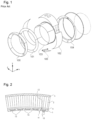
- FIG. 1 is an exploded perspective view of an air intake according to the prior art. This air intake is described in the introduction.
- FIG. 2 is a schematic cross-section view taken along a transverse plane of a portion of an acoustic panel corresponding to a first embodiment of the invention.
- FIG. 3 is a schematic perspective view of the resistive skin according to a second embodiment of an acoustic panel according to the invention.
- FIG. 4 is a schematic perspective view of the resistive skin of the first embodiment in FIG. 2 .
- FIG. 5 is a schematic perspective view of a first embodiment of the join between two successive panels with a resistive skin having transverse ribs.
- FIG. 6 is a schematic top view (in a centripetal direction) of a second embodiment of the join between two successive panels with a resistive skin having transverse ribs.
- FIG. 7 is a schematic top view of a third embodiment of the join between two successive panels with a resistive skin having transverse ribs.
- FIG. 8 is a transverse cross-section view of the join in FIG. 7 .
- FIG. 9 is a schematic perspective view of a fourth embodiment of the join between two successive panels with a resistive skin having transverse and longitudinal ribs.
- FIG. 10 is a schematic cross-section view of a fifth embodiment of the join between two successive panels.
- FIG. 11 is a schematic cross-section view of a sixth embodiment of the join between two successive panels.
- An acoustic panel according to the invention such as the one shown in FIGS. 2 and 4 , includes a resistive skin 1 , a core 2 having a cell structure that can be a honeycomb structure, and optionally a rear skin 3 .
- the resistive skin 1 has a castellated rear face 12 with alternating grooves 13 and ribs 14 , and a “smooth” front face 11 , i.e., with no steps or shoulders or grooves or other deformations/recesses or roughness (with the exception of the noise absorption holes).
- the face 12 of the skin is applied against the core, and therefore covers it entirely, the ribs thus forming recesses at the grooves between the skin and the smooth surface of the core.
- the resistive skin according to the invention has a first layer performing an acoustic function, corresponding to the thickness of the grooves and in which the noise absorption holes are formed, and a second layer performing a structural function on top of the first layer to form the ribs, this second layer therefore not covering the entire surface of the first layer.
- the thickness of the resistive skin 1 in the grooves 13 is preferably at least 30% less than the thickness of the resistive skin in the ribs 14 (thickness of the overlapping of the first acoustic layer and the second structural layer).
- the thickness of the resistive skin in the grooves 13 is preferably at most equal to 150% of the smallest dimension of the noise absorption holes (described below) in the case of circular or square noise absorption holes, or at most equal to 200% in the case of oblong holes.
- the resistive skin 1 is perforated (for example by punching) by noise absorption holes 10 to enable sound waves to penetrate the resistive skin 1 .
- these noise absorption holes are only formed in the grooves 13 .
- noise absorption holes 10 shown in the figures are circular, but the invention is not limited to this shape of hole.
- the diameter of the holes is preferably less than 0.6 mm depending on the ratio between the open surface (the holes) and the closed surface, this ratio being referred to as the open surface ratio (TSO) in the remainder of the description.
- the open surface ratio (TSO) is the percentage of open surface (the holes) in relation to the skin surface in question.
- TSO open surface ratio
- the holes For an open surface ratio (TSO) of between 0% and 2%, the holes have a diameter of less than 0.6 mm.
- the holes have a diameter of less than 0.3 mm.
- the diameter of the noise absorption holes is, for example, 0.1 mm for a resistive skin with a thickness of 0.15 mm in the grooves. According to another example, the diameter of the noise absorption holes is 0.2 mm for a resistive skin with a thickness of 0.3 mm in the grooves.
- the noise absorption holes 10 are then considered to be micro-perforations that cause little drag.
- noise absorption holes 10 can have different diameters or the same diameter, the second option simplifying manufacture.
- holes of different shapes for example oblong holes
- the oblong holes can have a length-to-width ratio of between 5 and 15.
- holes 0.3 mm wide and between 1.5 mm and 30 mm long could, for example, be provided.
- the holes can also be teardrop shaped or be of any other shape.
- At least one of the frontal dimensions of the holes is advantageously greater than or substantially equal to the thickness of the resistive skin in the grooves.
- the noise absorption holes are found at the bottom of the grooves, the thickness of which is significantly less than the thickness of the adjacent zones. This creates very thin open zones that are beneficial in terms of acoustics, and thick unbroken zones that are beneficial in terms of structural strength.
- the thickness at the hole which can be circular, slot shaped or shaped otherwise, can be reduced.
- the width of the grooves 13 and the width of the ribs 14 are determined as a function of the desired open surface ratio (TSO).
- TSO desired open surface ratio
- all of the grooves 13 are of the same width (which is not mandatory), for example on the order of 4 mm.
- all of the ribs are of the same width (which is not mandatory), which can be on the order of 2 mm.
- the resistive skin 1 can be built by assembling a first unbroken ply made of thermoplastic carbon, this first ply being the first acoustic layer, i.e., having the thickness of the skin in the grooves 13 , and a second ply made of thermoplastic carbon that is the second structural layer that forms the ribs 14 , the second ply having large openings in the form of longitudinal strips corresponding to the space between two ribs 14 .
- the first ply (or first layer) can be perforated or micro-perforated (before assembly) or be unperforated, in which case the noise absorption holes 10 are formed after the plies are assembled.
- each (structural, acoustic) layer can be formed by several plies.
- the resistive skin 1 can be formed from a single ply and obtained by molding.
- the absorption holes can be made after demolding or during molding.
- the shape of the section of the ribs and grooves is identical over at least a portion of the length thereof or over the entire length thereof.
- the ribs 14 and the grooves 13 are rectilinear and extend in longitudinal planes when the panel is viewed in position in an air intake.
- the ribs and grooves are at least partially parallelepipedic, i.e., for example of rectangular or trapezoidal or lozenge section, and can be entirely substantially parallelepipedic.
- the recesses formed in the grooves are therefore at least partially parallelepipedic and can be entirely substantially parallelepipedic.
- the acoustic panel also includes strengthening coils 4 between the resistive skin 1 and the core 2 of the panel.
- the strip 4 is interposed between the castellated skin and the core and thus moves the surface of the core away from the surface of the castellated skin described above identically, i.e., by the height of the strip 4 both in the ribs and in the grooves.
- the strip 4 forms a space of constant height that prevents any contact between the castellated skin and the core.
- These strengthening coils 4 are circumferential strips, each extending in a transverse plane (a plane orthogonal to the central axis of the air intake) over the ribs 14 .
- the coils 4 are designed to increase the mechanical strength of the resistive skin 1 .
- the thickness and width of the strengthening coils are determined as a function of the desired mechanical characteristics of the resistive skin 1 .
- the circumferential strips 4 extending in transverse planes can be replaced by a helical coil, i.e., by a single strip that winds about the resistive skin to form a helix, in which case the reinforcing strip does not extend in transverse planes.
- the resistive skin 1 of the first embodiment also has a rear flange 15 and a front flange 16 .
- the rear flange 15 closes the rear end of the panel over the entire thickness thereof, while the flange 16 only covers a portion of this thickness.
- the panel can have a front flange extending transversely as far as the rear skin of the panel, similarly to the rear flange 15 , or inversely a partial rear flange similar to the front flange 16 shown.
- the materials and manufacturing methods used confer a degree of rigidity on the resistive skin that is impossible to obtain from the rear and front flanges (which have opposing curvatures) extending in transverse planes, at 90° to the perforated portion of the resistive skin.
- the flanges are then formed with an “incline” of several degrees, which results in the flange having a significant longitudinal dimension that reduces the space available for the perforations and limits the open surface ratio (TSO) and the acoustic performance of the panel.
- the materials and manufacturing methods that can be implemented do not impose any constraints on the shape of the flanges, so that the entire length of the panel or nearly the entire length of the panel can be used for sound absorption, thereby improving the acoustic performance of the panel.
- FIG. 3 shows the resistive skin according to a second embodiment of an acoustic panel according to the invention.
- the resistive skin of this panel has alternating grooves 13 ′ and ribs 14 ′ extending in transverse planes. Similarly to the first embodiment, micro-perforations are provided in the thickness of the grooves 13 ′.
- the panel has a front flange 16 and a rear flange 15 that are similar to the flanges in the first embodiment.
- the panel does not have strengthening coils since the main forces are absorbed directly by the ribs 14 ′, the thickness of which can be designed to withstand these forces.
- Each panel has opposing longitudinal edges (each edge extending in a longitudinal plane containing the central axis of the air intake when the panel is installed in an air intake) that are rectilinear and have a thin longitudinal edge tongue 17 .
- the edge tongue 17 is wide enough to enable the panel to be correctly fastened to the adjacent panel, for example by swaging and gluing or welding.
- the edge tongue 17 has no absorption holes since it is designed to be covered by the edge tongue of the adjacent panel.
- the thickness of this edge tongue 17 corresponds, for example, to the thickness of the skin in the grooves (thickness of the first acoustic layer made of thermoplastic carbon).
- the thickness of resistive skin at the join between the two panels is therefore equal to twice the thickness in the grooves, i.e., the thickness of the ribs when the ribs are formed by a second layer of the same thickness as the first layer.
- FIG. 5 shows an assembly solution for two successive panels by fish-plating.
- each panel has, on each of the longitudinal sides thereof, a thin edge tongue 17 that is limited to the first skin layer and therefore has no ribs 14 ′.
- a rectangular fishplate 18 is arranged across the smooth rear faces of the adjacent edge tongues 17 of two successive panels. This fishplate 18 can be fastened to the two tongues by any suitable means (gluing, welding, etc.).
- FIG. 6 shows another fishplate 19 that can be used to assemble the resistive skin of the two panels in FIG. 5 .
- This fishplate 19 has a double-H shape.
- the arms 20 of the H-shapes transversely extend the transverse ribs 14 ′ of the panels, while the central bar 21 of the H-shapes extends longitudinally at the join between the two panels.
- FIG. 7 shows another assembly solution for two successive panels by fish-plating, in the case of panels having a resistive skin with transverse ribs 14 ′.
- the ribs themselves act as fishplates.
- Each panel has a first thin edge tongue 17 on one side that is the first acoustic layer, as in the above examples.
- the panel has a second thin edge tongue 22 that is the second structural layer of the skin.
- the second layer comprises transverse strips 14 ′ forming ribs.
- the second edge tongue 22 therefore comprises portions of transverse strips (ribs) that are separated from one another and that project from the edge 24 of the first acoustic layer over an overhang width that is, for example, on the order of 25 mm.
- the panels are arranged such that the ribs 14 ′ of one of the panels extend the ribs 14 ′ of the other panel (and vice versa) and preferably such that the projecting portion 23 of the ribs of the second edge tongue of the first panel overlap the ribs of the second panel over a width “a” (see FIG. 8 ) that is, for example, on the order of 20 mm.
- the first edge tongue 17 of the second panel is then arranged in part beneath the skin of the first panel over a width “b” on the order of 5 mm.
- the first layers of the resistive skins of the two panels can be arranged edge-to-edge, although this is less efficient since it is not desirable for the air to be able to flow directly between the two panels at the join therebetween.
- the step 25 created on the visible face of the panels at the join therebetween has little aerodynamic impact since this step is longitudinal and therefore in the flow direction.
- FIG. 9 shows another assembly solution for two successive panels by fish-plating.
- each panel comprises a first edge tongue formed exclusively by the first layer of the skin and, on the opposite side, a second edge tongue formed exclusively by the second layer of the skin.
- the second structural layer differs from the second structural layer in the previous example in that it includes a continuous surface perforated by rectangular openings 28 to create transverse ribs 26 and longitudinal ribs 27 simultaneously.
- the panels can be arranged edge-to-edge.
- the second edge tongue 22 entirely overlaps the first edge tongue 17 .
- the first edge tongue 17 has noise absorption holes since the second edge tongue 22 has openings 28 that enable passage of the sound waves absorbed through the holes in the first edge tongue 17 .
- the panels in FIG. 9 can also be arranged with an overlap as explained above, in which case the overlap is determined such that the row of openings 28 of the second edge tongue 22 of the first panel overlaps the first row of openings 28 of the second panel.
- FIG. 10 shows another assembly solution for two successive panels by fish-plating.
- the skin of each panel comprises an overlap of at least three plies (it should be noted that the sum of the three plies can constitute the thickness of the skin at the ribs or of the first acoustic layer only).
- Each panel has a first edge tongue 29 with two steps (or shoulders) on the front face thereof, and a second edge tongue 30 with two steps (or shoulders) on the rear face thereof. The steps correspond to the transition from one ply to another.
- Two successive panels are assembled by lapping (and fastening by gluing or welding for example) the first edge tongue 29 of one of the panels and the second edge tongue 30 of the other panel.
- This solution is good for panels in which the resistive skin has longitudinal or transverse ribs or both types of ribs (not shown in FIG. 10 ).
- FIG. 11 shows another assembly solution for two successive panels using a scarf joint.
- Each panel has a first edge tongue 31 with a beveled front face, and a second edge tongue 32 with a beveled rear face.
- the front and back bevels of the edge tongues are formed over a width “c” that can range from 10 mm to 30 mm, and over a thickness that corresponds to the first acoustic layer or to the total thickness of the skin (at the ribs).
- Two successive panels are assembled by lapping and fastening (by gluing or welding for example) the first edge tongue 31 with a front bevel of one of the panels and the second edge tongue 32 with a back bevel of the other panel.
- This solution is good for panels in which the resistive skin has longitudinal or transverse ribs or both types of ribs (not shown in FIG. 11 ).
Landscapes
- Engineering & Computer Science (AREA)
- Chemical & Material Sciences (AREA)
- Combustion & Propulsion (AREA)
- Aviation & Aerospace Engineering (AREA)
- Mechanical Engineering (AREA)
- General Engineering & Computer Science (AREA)
- Physics & Mathematics (AREA)
- Acoustics & Sound (AREA)
- Multimedia (AREA)
- Soundproofing, Sound Blocking, And Sound Damping (AREA)
- Body Structure For Vehicles (AREA)
Applications Claiming Priority (2)
| Application Number | Priority Date | Filing Date | Title |
|---|---|---|---|
| FR1910029A FR3100916A1 (fr) | 2019-09-12 | 2019-09-12 | Panneau acoustique d'entrée d'air de nacelle d'aéronef à peau résistive crénelée, et ensemble propulsif et aéronef équipés de tels panneaux acoustiques |
| FR1910029 | 2019-09-12 |
Publications (2)
| Publication Number | Publication Date |
|---|---|
| US20210078717A1 US20210078717A1 (en) | 2021-03-18 |
| US11649063B2 true US11649063B2 (en) | 2023-05-16 |
Family
ID=69024367
Family Applications (1)
| Application Number | Title | Priority Date | Filing Date |
|---|---|---|---|
| US17/017,429 Active 2041-02-02 US11649063B2 (en) | 2019-09-12 | 2020-09-10 | Acoustic panel for an aircraft nacelle air inlet with castellated resistive skin, propulsion unit and aircraft fitted with such acoustic panels |
Country Status (4)
| Country | Link |
|---|---|
| US (1) | US11649063B2 (fr) |
| EP (1) | EP3792910A1 (fr) |
| CN (1) | CN112478180A (fr) |
| FR (1) | FR3100916A1 (fr) |
Families Citing this family (2)
| Publication number | Priority date | Publication date | Assignee | Title |
|---|---|---|---|---|
| FR3130755A1 (fr) * | 2021-12-20 | 2023-06-23 | Airbus Operations | Dispositif de chauffage à matelas chauffant pour un système de protection contre le givre d’un aéronef. |
| CN116931507B (zh) * | 2023-09-18 | 2024-01-12 | 成都飞机工业(集团)有限责任公司 | 一种群孔穿孔控制方法、装置、存储介质及电子设备 |
Citations (9)
| Publication number | Priority date | Publication date | Assignee | Title |
|---|---|---|---|---|
| US20020157764A1 (en) * | 1999-12-24 | 2002-10-31 | Robert Andre | Method for making a sound reducing panel with resistive layer having structural property and resulting panel |
| US20060219475A1 (en) * | 2005-03-30 | 2006-10-05 | Olsen Ronald F | Flow restrictors for aircraft inlet acoustic treatments, and associated systems and methods |
| EP2216773A1 (fr) | 2009-02-04 | 2010-08-11 | Eichhorn GmbH & Co. KG | Procédé et appareil de fabrication d'un panneau absorbant le son et un tel panneau |
| WO2012145141A1 (fr) | 2011-04-20 | 2012-10-26 | Dresser-Rand Company | Groupement de résonateurs à multiples degrés de liberté |
| US20120317782A1 (en) | 2011-06-20 | 2012-12-20 | Airbus Operations Sas | Process for the Production of a Panel for the Acoustic Treatment Incorporating the Frost Treatment Function with Hot Air |
| US20150071760A1 (en) | 2013-09-11 | 2015-03-12 | Dresser-Rand Company | Acoustic resonators for compressors |
| US20200070949A1 (en) * | 2018-09-05 | 2020-03-05 | Airbus Operations S.A.S. | Sound-Absorbing Panel With A Cellular Core And A De-Icing System |
| US20200276641A1 (en) * | 2017-09-06 | 2020-09-03 | Safran Nacelles | Method for manufacturing a cellular core for an acoustic panel |
| US20210078718A1 (en) * | 2019-09-12 | 2021-03-18 | Airbus Operations Sas | Air inlet, nacelle, propulsive assembly and aircraft with grooved lip |
Family Cites Families (3)
| Publication number | Priority date | Publication date | Assignee | Title |
|---|---|---|---|---|
| JP2009062977A (ja) * | 2007-08-15 | 2009-03-26 | Rohr Inc | 線形音響ライナー |
| FR2956513B1 (fr) * | 2010-02-17 | 2012-08-31 | Snecma | Panneau de traitement acoustique. |
| TWI564456B (zh) * | 2014-09-12 | 2017-01-01 | Gan-Yang Yan | Sound insulation structure of the insulation board |
-
2019
- 2019-09-12 FR FR1910029A patent/FR3100916A1/fr active Pending
-
2020
- 2020-09-09 EP EP20195187.8A patent/EP3792910A1/fr active Pending
- 2020-09-10 US US17/017,429 patent/US11649063B2/en active Active
- 2020-09-11 CN CN202010950492.6A patent/CN112478180A/zh active Pending
Patent Citations (11)
| Publication number | Priority date | Publication date | Assignee | Title |
|---|---|---|---|---|
| US20020157764A1 (en) * | 1999-12-24 | 2002-10-31 | Robert Andre | Method for making a sound reducing panel with resistive layer having structural property and resulting panel |
| US20060219475A1 (en) * | 2005-03-30 | 2006-10-05 | Olsen Ronald F | Flow restrictors for aircraft inlet acoustic treatments, and associated systems and methods |
| EP2216773A1 (fr) | 2009-02-04 | 2010-08-11 | Eichhorn GmbH & Co. KG | Procédé et appareil de fabrication d'un panneau absorbant le son et un tel panneau |
| WO2012145141A1 (fr) | 2011-04-20 | 2012-10-26 | Dresser-Rand Company | Groupement de résonateurs à multiples degrés de liberté |
| US20140034416A1 (en) | 2011-04-20 | 2014-02-06 | Dresser-Rand Company | Multi-degree of freedom resonator array |
| US20120317782A1 (en) | 2011-06-20 | 2012-12-20 | Airbus Operations Sas | Process for the Production of a Panel for the Acoustic Treatment Incorporating the Frost Treatment Function with Hot Air |
| EP2537753A1 (fr) | 2011-06-20 | 2012-12-26 | Airbus Opérations SAS | Procédé de réalisation d'un panneau pour le traitement acoustique integrant la fonction de traitement du givre avec de l'air chaud |
| US20150071760A1 (en) | 2013-09-11 | 2015-03-12 | Dresser-Rand Company | Acoustic resonators for compressors |
| US20200276641A1 (en) * | 2017-09-06 | 2020-09-03 | Safran Nacelles | Method for manufacturing a cellular core for an acoustic panel |
| US20200070949A1 (en) * | 2018-09-05 | 2020-03-05 | Airbus Operations S.A.S. | Sound-Absorbing Panel With A Cellular Core And A De-Icing System |
| US20210078718A1 (en) * | 2019-09-12 | 2021-03-18 | Airbus Operations Sas | Air inlet, nacelle, propulsive assembly and aircraft with grooved lip |
Non-Patent Citations (1)
| Title |
|---|
| French Search Report; priority document. |
Also Published As
| Publication number | Publication date |
|---|---|
| US20210078717A1 (en) | 2021-03-18 |
| FR3100916A1 (fr) | 2021-03-19 |
| EP3792910A1 (fr) | 2021-03-17 |
| CN112478180A (zh) | 2021-03-12 |
Similar Documents
| Publication | Publication Date | Title |
|---|---|---|
| US11649063B2 (en) | Acoustic panel for an aircraft nacelle air inlet with castellated resistive skin, propulsion unit and aircraft fitted with such acoustic panels | |
| EP3324400B1 (fr) | Panneau acoustique avec longerons de paroi latérale | |
| US11208193B2 (en) | Sound attenuation panel for an aircraft | |
| US6761245B2 (en) | Tubular acoustic attenuation piece for an aircraft jet engine air intake | |
| US9897007B2 (en) | Thrust reverser-integrated track beam and inner fixed structure | |
| US8646574B2 (en) | Acoustic skin for an aircraft nacelle acoustic panel | |
| US7798285B2 (en) | Acoustic barrel for aircraft engine nacelle including crack and delamination stoppers | |
| JP6781676B2 (ja) | 成形遮音構造形成方法 | |
| US9162747B2 (en) | Method for manufacturing a sound attenuation panel | |
| US11027817B2 (en) | Acoustic treatment panel comprising a porous acoustically resistive structure comprising connecting canals | |
| US10940935B2 (en) | Acoustic treatment panel comprising cells which each contain a plurality of conduits | |
| US20130133977A1 (en) | Acoustic panel for a turbojet engine nacelle, with in-built fasteners | |
| US10507931B2 (en) | Panel and insert for corner radii | |
| CN112189089B (zh) | 用于飞行器喷气发动机短舱的声学衰减板 | |
| US11459950B2 (en) | Sound attenuation panel for aircraft having a combination of acoustic attenuation properties | |
| CN101636575A (zh) | 一种消音衬垫的实施方法及用此方法获得的衬垫 | |
| US10723476B2 (en) | Ring of turbojet vanes including an acoustic treatment structure | |
| US11066994B2 (en) | Assembly comprising two juxtaposed acoustic panels in which the panels comprise a resistive face which extends as far as an end wall | |
| US20200223158A1 (en) | Method For Producing An Acoustically Resistive Structure, Acoustically Resistive Structure Thus Obtained, And Sound-Absorption Panel Comprising Said Acoustically Resistive Structure | |
| RU2247878C2 (ru) | Способ изготовления звукопоглощающей конструкции газового тракта | |
| US12054275B2 (en) | Resistive skin shell incorporating perforated metal bands, and acoustic inner wall of an aircraft air intake formed from such resistive skin shells | |
| US20220034260A1 (en) | Strip-form acoustic material having an integrated flange, and internal wall of an aircraft air intake made with this material | |
| CN114730559A (zh) | 声音衰减板及其制造方法 | |
| CN117730197A (zh) | 用于飞行器推进单元的加强声学处理面板 |
Legal Events
| Date | Code | Title | Description |
|---|---|---|---|
| FEPP | Fee payment procedure |
Free format text: ENTITY STATUS SET TO UNDISCOUNTED (ORIGINAL EVENT CODE: BIG.); ENTITY STATUS OF PATENT OWNER: LARGE ENTITY |
|
| AS | Assignment |
Owner name: AIRBUS OPERATIONS SAS, FRANCE Free format text: ASSIGNMENT OF ASSIGNORS INTEREST;ASSIGNORS:PORTE, ALAIN;LALANE, JACQUES;PRZYBYLA, BENOIT;AND OTHERS;SIGNING DATES FROM 20200908 TO 20200914;REEL/FRAME:053874/0088 |
|
| STPP | Information on status: patent application and granting procedure in general |
Free format text: APPLICATION DISPATCHED FROM PREEXAM, NOT YET DOCKETED |
|
| STPP | Information on status: patent application and granting procedure in general |
Free format text: DOCKETED NEW CASE - READY FOR EXAMINATION |
|
| STPP | Information on status: patent application and granting procedure in general |
Free format text: NON FINAL ACTION MAILED |
|
| STPP | Information on status: patent application and granting procedure in general |
Free format text: RESPONSE TO NON-FINAL OFFICE ACTION ENTERED AND FORWARDED TO EXAMINER |
|
| STPP | Information on status: patent application and granting procedure in general |
Free format text: NON FINAL ACTION MAILED |
|
| STCF | Information on status: patent grant |
Free format text: PATENTED CASE |