US11648833B2 - Support bracket for mounting transmission and mounting assembly provided with the same - Google Patents
Support bracket for mounting transmission and mounting assembly provided with the same Download PDFInfo
- Publication number
- US11648833B2 US11648833B2 US17/191,232 US202117191232A US11648833B2 US 11648833 B2 US11648833 B2 US 11648833B2 US 202117191232 A US202117191232 A US 202117191232A US 11648833 B2 US11648833 B2 US 11648833B2
- Authority
- US
- United States
- Prior art keywords
- nut
- insert portion
- engaging
- bolt
- support bracket
- Prior art date
- Legal status (The legal status is an assumption and is not a legal conclusion. Google has not performed a legal analysis and makes no representation as to the accuracy of the status listed.)
- Active, expires
Links
- 230000005540 biological transmission Effects 0.000 title claims description 9
- 238000000926 separation method Methods 0.000 claims abstract description 8
- 239000003638 chemical reducing agent Substances 0.000 claims description 4
- 238000004519 manufacturing process Methods 0.000 description 10
- 238000000034 method Methods 0.000 description 5
- 229920003002 synthetic resin Polymers 0.000 description 5
- 239000000057 synthetic resin Substances 0.000 description 5
- 229910052782 aluminium Inorganic materials 0.000 description 2
- XAGFODPZIPBFFR-UHFFFAOYSA-N aluminium Chemical compound [Al] XAGFODPZIPBFFR-UHFFFAOYSA-N 0.000 description 2
- 230000000694 effects Effects 0.000 description 2
- 239000012212 insulator Substances 0.000 description 2
- 239000000463 material Substances 0.000 description 2
- 230000000149 penetrating effect Effects 0.000 description 2
- 238000004512 die casting Methods 0.000 description 1
- 238000001746 injection moulding Methods 0.000 description 1
- 229910052751 metal Inorganic materials 0.000 description 1
- 239000002184 metal Substances 0.000 description 1
- 238000012986 modification Methods 0.000 description 1
- 230000004048 modification Effects 0.000 description 1
Images


Classifications
-
- B—PERFORMING OPERATIONS; TRANSPORTING
- B60—VEHICLES IN GENERAL
- B60K—ARRANGEMENT OR MOUNTING OF PROPULSION UNITS OR OF TRANSMISSIONS IN VEHICLES; ARRANGEMENT OR MOUNTING OF PLURAL DIVERSE PRIME-MOVERS IN VEHICLES; AUXILIARY DRIVES FOR VEHICLES; INSTRUMENTATION OR DASHBOARDS FOR VEHICLES; ARRANGEMENTS IN CONNECTION WITH COOLING, AIR INTAKE, GAS EXHAUST OR FUEL SUPPLY OF PROPULSION UNITS IN VEHICLES
- B60K5/00—Arrangement or mounting of internal-combustion or jet-propulsion units
- B60K5/12—Arrangement of engine supports
- B60K5/1291—Supports comprising stoppers
-
- B—PERFORMING OPERATIONS; TRANSPORTING
- B60—VEHICLES IN GENERAL
- B60K—ARRANGEMENT OR MOUNTING OF PROPULSION UNITS OR OF TRANSMISSIONS IN VEHICLES; ARRANGEMENT OR MOUNTING OF PLURAL DIVERSE PRIME-MOVERS IN VEHICLES; AUXILIARY DRIVES FOR VEHICLES; INSTRUMENTATION OR DASHBOARDS FOR VEHICLES; ARRANGEMENTS IN CONNECTION WITH COOLING, AIR INTAKE, GAS EXHAUST OR FUEL SUPPLY OF PROPULSION UNITS IN VEHICLES
- B60K17/00—Arrangement or mounting of transmissions in vehicles
- B60K17/04—Arrangement or mounting of transmissions in vehicles characterised by arrangement, location, or kind of gearing
- B60K17/06—Arrangement or mounting of transmissions in vehicles characterised by arrangement, location, or kind of gearing of change-speed gearing
-
- F—MECHANICAL ENGINEERING; LIGHTING; HEATING; WEAPONS; BLASTING
- F16—ENGINEERING ELEMENTS AND UNITS; GENERAL MEASURES FOR PRODUCING AND MAINTAINING EFFECTIVE FUNCTIONING OF MACHINES OR INSTALLATIONS; THERMAL INSULATION IN GENERAL
- F16B—DEVICES FOR FASTENING OR SECURING CONSTRUCTIONAL ELEMENTS OR MACHINE PARTS TOGETHER, e.g. NAILS, BOLTS, CIRCLIPS, CLAMPS, CLIPS OR WEDGES; JOINTS OR JOINTING
- F16B39/00—Locking of screws, bolts or nuts
-
- F—MECHANICAL ENGINEERING; LIGHTING; HEATING; WEAPONS; BLASTING
- F16—ENGINEERING ELEMENTS AND UNITS; GENERAL MEASURES FOR PRODUCING AND MAINTAINING EFFECTIVE FUNCTIONING OF MACHINES OR INSTALLATIONS; THERMAL INSULATION IN GENERAL
- F16B—DEVICES FOR FASTENING OR SECURING CONSTRUCTIONAL ELEMENTS OR MACHINE PARTS TOGETHER, e.g. NAILS, BOLTS, CIRCLIPS, CLAMPS, CLIPS OR WEDGES; JOINTS OR JOINTING
- F16B5/00—Joining sheets or plates, e.g. panels, to one another or to strips or bars parallel to them
- F16B5/02—Joining sheets or plates, e.g. panels, to one another or to strips or bars parallel to them by means of fastening members using screw-thread
-
- B—PERFORMING OPERATIONS; TRANSPORTING
- B60—VEHICLES IN GENERAL
- B60K—ARRANGEMENT OR MOUNTING OF PROPULSION UNITS OR OF TRANSMISSIONS IN VEHICLES; ARRANGEMENT OR MOUNTING OF PLURAL DIVERSE PRIME-MOVERS IN VEHICLES; AUXILIARY DRIVES FOR VEHICLES; INSTRUMENTATION OR DASHBOARDS FOR VEHICLES; ARRANGEMENTS IN CONNECTION WITH COOLING, AIR INTAKE, GAS EXHAUST OR FUEL SUPPLY OF PROPULSION UNITS IN VEHICLES
- B60K5/00—Arrangement or mounting of internal-combustion or jet-propulsion units
- B60K5/12—Arrangement of engine supports
- B60K5/1208—Resilient supports
-
- B—PERFORMING OPERATIONS; TRANSPORTING
- B60—VEHICLES IN GENERAL
- B60Y—INDEXING SCHEME RELATING TO ASPECTS CROSS-CUTTING VEHICLE TECHNOLOGY
- B60Y2304/00—Optimising design; Manufacturing; Testing
- B60Y2304/05—Reducing production costs, e.g. by redesign
-
- B—PERFORMING OPERATIONS; TRANSPORTING
- B60—VEHICLES IN GENERAL
- B60Y—INDEXING SCHEME RELATING TO ASPECTS CROSS-CUTTING VEHICLE TECHNOLOGY
- B60Y2304/00—Optimising design; Manufacturing; Testing
- B60Y2304/07—Facilitating assembling or mounting
Definitions
- the present disclosure relates to a support bracket for mounting a power train and a mounting assembly including the same. More particularly, the present disclosure relates to a support bracket for mounting a power train and a mounting assembly including the same, which can simplify the assembly process and reduce manufacturing cost.
- a power train of a vehicle is a device that generates power and transmits the power to the driving wheel by changing torque and speed to suit the vehicle's running state.
- the power train generates a lot of vibration and noise due to the influence of engine and transmission driving.
- a power train is mounted on the vehicle body frame using a power train mount.
- the powertrain mount is bolted to a front side member forming an engine compartment.
- This powertrain mount is connected to a powertrain fixing bracket which is bolted to a powertrain case, and the powertrain mount is connected to the bracket for mounting the powertrain through a bolt penetrating through an insulator provided therein.
- the conventional powertrain fixing bracket used as a medium connecting the powertrain and the powertrain mount is mainly made of the same aluminum as the powertrain case, and a square nut is used to be fastened with a bolt penetrating the powertrain mount.
- the conventional power train fixing bracket forms a pocket in which a square nut can be installed, so that the square nut is positioned in the pocket.
- a stopper made of metal plate is fixed to the bracket for mounting the power train by bolts so that the square nut positioned in the pocket does not come off.
- Conventional powertrain fixing brackets have an inferior moldability compared to injection molding using synthetic resin because the material is made of aluminum, the material cost is high, and it is manufactured by die casting.
- the stopper preventing the separation of the square nut has a complicated bent shape so that the square nut allows movement in the pocket and does not escape from the pocket, the manufacturing cost increases and the manufacturing process is complicated.
- the present disclosure has been made in an effort to provide a support bracket for mounting a power train and a mounting assembly including the same, which can simplify the assembly process and reduce manufacturing cost.
- a support bracket for mounting a power train may include a bracket body including an engaging hole formed to insert an engaging bolt of a power train mount, an insert portion formed adjacent to the engaging hole, and a pocket formed adjacent to the insert portion, and an engaging nut inserted in the insert portion along the insert direction to engage the engaging bolt, and a stopper configured to prevent the engaging nut from separation.
- the engaging bolt may include a first bolt and a second bolt parallel to the first bolt, the engaging hole may include a first engaging hole and a second engaging hole into which the first bolt and the second bolt are respectively inserted, the engaging nut may include a first nut and a second nut that are respectively engaged with the first bolt and the second bolt, and the insert portion may include a first insert portion and a second insert portion into which the first nut and the second nut are respectively inserted.
- the insert direction may be an axial direction of the engaging bolt, and the stopper may be formed to limit the movement of the engaging nut along the axial direction of the engaging bolt.
- the support bracket according to an exemplary embodiment of the present disclosure may further include a rib formed inside the pocket to divide the first insert portion and the second insert portion.
- the stopper may be formed on at least one of the interior surfaces of the rib or the pocket.
- the stopper may include a first stopper formed on the rib, and a second stopper formed on the interior surface of the pocket.
- the stopper may include an inclined portion formed along the insert direction of the engaging nut.
- An assemble hole into which the engaging nut is inserted may be formed in a direction perpendicular to the axial direction of the engaging bolt in the bracket body, and the first insert portion and the second insert portion may be formed in the assemble hole.
- the stopper may be formed so that the first nut and the second nut are not separated from the first insert portion and the second insert portion.
- the support bracket according to an exemplary embodiment of the present disclosure may further include ribs formed adjacent to the first insert portion and the second insert portion.
- the ribs may include a horizontal rib and a vertical rib connected to the horizontal rib perpendicularly and formed adjacent to the first insert portion and the second insert portion.
- a first rib hole in which the first bolt protrudes and a second rib hole in which the second bolt protrudes may be formed in the vertical rib.
- the power train mount may combine at least one of an engine, a transmission, a motor and a reducer to the vehicle body.
- a mounting assembly may include a power train mount, a first nut and a second nut, a bracket body in which a first engaging hole and a second engaging hole are formed, a first insert portion and a second insert portion into which the first nut and the second nut are respectively inserted are formed, and a pocket is formed adjacent to the first insert portion and the second insert portion, and a first bolt and a second bolt that engage with the first nut and second nut, respectively, to connect the power train mount and the bracket body, wherein, a stopper may be formed to prevent the first nut and second nut from separation.
- the mounting assembly may further include a rib formed inside the pocket to divide the first insert portion and the second insert portion.
- the stopper may be formed on at least one of the interior surfaces of the rib or the pocket.
- the stopper may include an inclined portion formed along the insert direction of the engaging nut.
- An assemble hole into which the engaging nut is inserted may be formed in a direction perpendicular to the axial direction of the engaging bolt in the bracket body, and the first insert portion and the second insert portion may be formed in the assemble hole.
- the mounting assembly may further include ribs formed adjacent to the first insert portion and the second insert portion.
- the ribs may include a horizontal rib, and a vertical rib connected to the horizontal rib perpendicularly and formed adjacent to the first insert portion and the second insert portion.
- a support bracket for mounting a power train and a mounting assembly including the same can simplify the configuration and reduce the number of parts, thereby simplifying the assembly process and reducing manufacturing costs.
- FIG. 1 is a perspective view of a mounting assembly according to an exemplary embodiment of the present disclosure.
- FIG. 2 is a cross-sectional view along the line II-II of FIG. 1 .
- FIG. 3 is a perspective view of a support bracket for mounting a power train according to an exemplary embodiment of the present disclosure.
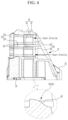
- FIG. 4 is a cross-sectional view along the line IV-IV of FIG. 3 .
- FIG. 5 is a perspective view of a support bracket for mounting a power train according to another exemplary embodiment of the present disclosure.
- FIG. 6 is a cross-sectional view along the line VI-VI of FIG. 5 .
- FIG. 7 is a perspective cross-sectional view along the line VI-VI of FIG. 5 .
- FIG. 1 is a perspective view of a mounting assembly according to an exemplary embodiment of the present disclosure
- FIG. 2 is a cross-sectional view along the line II-II of FIG. 1 .
- a mounting assembly 10 includes a power train mount 20 mounted on a vehicle body 12 and a support bracket 30 for mounting a power train connected to a power train 14 .
- the vehicle body 12 may be, for example, a side member, and the support bracket 30 for mounting a power train may be mounted to, for example, a power train housing 14 .
- the power train mount 20 and the support bracket 30 can be joined via engaging bolt 22 .
- the power train 14 may include at least one of an engine, a transmission, a motor and a reducer, and the power train mount 20 may combine at least one of the engine, the transmission, the motor and the reducer to the vehicle body 12 can do.
- FIG. 3 is a perspective view of a support bracket for mounting a power train according to an exemplary embodiment of the present disclosure
- FIG. 4 is a cross-sectional view along the line IV-IV of FIG. 3 .
- the support bracket 30 which can be applied to the mounting assembly 10 according to an exemplary embodiment of the present disclosure, may include a bracket body 50 including an engaging hole 52 formed to insert the engaging bolt 22 of the power train mount 20 , an insert portion 60 formed adjacent to the engaging hole 52 and a pocket 70 formed adjacent to the insert portion 60 .
- the support bracket 30 may further include an engaging nut 40 inserted in the insert portion 60 along the insert direction to engage the engaging bolt 22 .
- a stopper 80 can be formed to prevent the engaging nut 40 from separation.
- the engaging bolt 22 may include a first bolt 24 and a second bolt 26 parallel to the first bolt 24 . That is, the first bolt 24 and the second bolt 26 are formed in a direction parallel to the vibration transmission direction transmitted from the power train housing 14 , so that the vibration transmitted to the insulator of the power train mount 20 can be reduced.
- the engaging hole 52 may include a first engaging hole 54 and a second engaging hole 56 into which the first bolt 24 and the second bolt 26 are respectively inserted, and the engaging nut 40 may include a first nut 42 and a second nut 44 that are respectively engaged with the first bolt 24 and the second bolt 26 .
- Bushes 95 may be inserted into the first engaging hole 54 and the second engaging hole 56 , respectively, to support the first bolt 24 and the second bolt 26 .
- the insert portion 60 may include a first insert portion 62 and a second insert portion 64 into which the first nut 42 and the second nut 44 are respectively inserted.
- the insert direction may be an axial direction of the engaging bolt 22
- the stopper 80 may be formed to limit the movement of the engaging nut 40 along the axial direction of the engaging bolt 22 .
- first insert portion 62 and the second insert portion 64 may be formed inside the pocket 70 along the axial direction of the first bolt 24 and the second bolt 26 .
- a support bracket 30 for mounting a power train may further include a rib 90 formed inside the pocket 70 to divide the first insert portion 62 and the second insert portion 64 .
- the shape of the pocket 70 formed in the bracket body 50 facilitates the assemble of the first nut 42 and the second nut 44 , and deformation of the bracket body 50 by the vibration and load transmitted from the power train housing 14 can be prevented.
- the rib 90 is formed inside the pocket 70 , so that the strength of the bracket body 50 can be additionally increased.
- the stopper 80 is formed on at least one of the interior surfaces of the rib 90 or the pocket 70 to prevent the first nut 42 and the second nut 44 from separation.
- the stopper 80 may include a first stopper 82 formed on the rib 90 and a second stopper 84 formed on the interior surface of the pocket 70 , but is not limited thereto, may be formed above and below the rib 90 , may be formed on the inner side of the first insert portion 62 and the second insert portion 64 .
- the stopper 80 may include an inclined portion 86 formed along the insert direction of the engaging nut 40 .
- the bracket body 50 may be formed of synthetic resin.
- the first nut 42 and the second nut 44 are smoothly inserted into the first insert portion 62 and the second insert portion 64 by the inclined portion 86 , but are prevented from being separated from the first insert portion 62 and the second insert portion 64 .
- the bracket body 50 is formed of synthetic resin, the stopper 80 can be transformed to a small degree, making it easy to insert the first nut 42 and the second nut 44 .
- the engaging nut 40 contacts the interior surfaces of the first insert portion 62 and the second insert portion 64 , and can be fixed when it is combined with the first bolt 24 and the second bolt 26 .
- the engaging nut 40 is shown as a square shape in the drawing, but is not limited thereto, and can be formed in a polygon shape, for example a pentagonal, hexagonal, or octagonal shape. In other words, various shapes that is fixed when combined with the first bolt 24 and the second bolt 26 can be applied.
- FIG. 5 is a perspective view of a support bracket for mounting a power train according to another exemplary embodiment of the present disclosure
- FIG. 6 is a cross-sectional view along the line VI-VI of FIG. 5
- FIG. 7 is a perspective cross-sectional view along the line VI-VI of FIG. 5 .
- a support bracket 31 for mounting a power train includes a bracket body 51 , and in the bracket body 51 , an assemble hole 100 into which the engaging nut 40 is inserted is formed in perpendicular to the axial direction of the engaging bolt 22 .
- An insert portion 101 into which the engaging nut 40 is inserted is formed in the assemble hole 100 . That is, a first insert portion 102 and a second insert portion 104 into which the first nut 42 and the second nut 44 coupled with the first bolt 24 and the second bolt 26 are respectively inserted may be formed in the assemble hole 100 .
- a support bracket 31 for mounting a power train the first nut 42 and the second nut 44 may be inserted from the lower portion of the bracket body 51 to the upper portion.
- Stoppers 110 may be formed so that the first nut 42 and the second nut 44 are not separated from the first insert portion 102 and the second insert portion 104 , respectively.
- a support bracket 31 for mounting a power train may further include ribs 130 formed adjacent to the first insert portion 102 and the second insert portion 104 .
- the ribs 130 may include a horizontal rib 132 and a vertical rib 134 connected to the horizontal rib 132 perpendicularly and formed adjacent to the first insert portion 102 and the second insert portion 104 .
- a first rib hole 136 in which the first bolt 24 is protruded and a second rib hole 138 in which the second bolt 26 is protruded may be formed in the vertical rib 134 .
- the first bolt 24 and the second bolt 26 may protrude through the first rib hole 136 and the second rib hole 138 .
- the horizontal rib 132 can reinforce the strength of the bracket body 51 by connecting the inside of pocket 12 formed in the bracket body 51 , and the first and second rib holes 136 , and 138 of the vertical rib 134 support the first bolt 24 and the second bolt 26 to reinforce the strength of the bracket body 51 .
- a support bracket for mounting a power train and a mounting assembly including the same can simplify the configuration and reduce the number of parts, thereby simplifying the assembly process and reducing manufacturing costs.
- the assemble process of the engaging bolt and the engaging nut can be simplified by fixing the engaging nut without separate components of a complex configuration.
Landscapes
- Engineering & Computer Science (AREA)
- Mechanical Engineering (AREA)
- Chemical & Material Sciences (AREA)
- Combustion & Propulsion (AREA)
- Transportation (AREA)
- General Engineering & Computer Science (AREA)
- Arrangement Or Mounting Of Propulsion Units For Vehicles (AREA)
Applications Claiming Priority (2)
| Application Number | Priority Date | Filing Date | Title |
|---|---|---|---|
| KR1020200127880A KR20220045320A (ko) | 2020-10-05 | 2020-10-05 | 파워트레인 고정용 서포트 브라켓 및 이를 포함하는 마운팅 어셈블리 |
| KR10-2020-0127880 | 2020-10-05 |
Publications (2)
| Publication Number | Publication Date |
|---|---|
| US20220105792A1 US20220105792A1 (en) | 2022-04-07 |
| US11648833B2 true US11648833B2 (en) | 2023-05-16 |
Family
ID=80738150
Family Applications (1)
| Application Number | Title | Priority Date | Filing Date |
|---|---|---|---|
| US17/191,232 Active 2041-08-31 US11648833B2 (en) | 2020-10-05 | 2021-03-03 | Support bracket for mounting transmission and mounting assembly provided with the same |
Country Status (4)
| Country | Link |
|---|---|
| US (1) | US11648833B2 (zh) |
| KR (1) | KR20220045320A (zh) |
| CN (1) | CN114379351A (zh) |
| DE (1) | DE102021109641A1 (zh) |
Families Citing this family (1)
| Publication number | Priority date | Publication date | Assignee | Title |
|---|---|---|---|---|
| KR20230010288A (ko) * | 2021-07-12 | 2023-01-19 | 현대자동차주식회사 | 자동차용 트랜스미션 마운트 |
Citations (5)
| Publication number | Priority date | Publication date | Assignee | Title |
|---|---|---|---|---|
| US4056249A (en) * | 1975-06-25 | 1977-11-01 | Kabushiki Kaisha Komatsu Seisakusho | Engine mounting apparatus |
| KR101818662B1 (ko) | 2017-05-29 | 2018-01-15 | 인지컨트롤스 주식회사 | 차량용 트랜스미션 고정용 브라켓 |
| US20180172135A1 (en) * | 2016-12-16 | 2018-06-21 | Hyundai Motor Company | Low porosity solid electrolyte membrane and method for manufacturing the same |
| US10208847B1 (en) * | 2017-08-21 | 2019-02-19 | Hyundai Motor Company | Structure of transmission mount |
| US20190120365A1 (en) * | 2017-10-23 | 2019-04-25 | Hyundai Motor Company | Transmission mount |
-
2020
- 2020-10-05 KR KR1020200127880A patent/KR20220045320A/ko active Search and Examination
-
2021
- 2021-03-03 US US17/191,232 patent/US11648833B2/en active Active
- 2021-04-16 DE DE102021109641.3A patent/DE102021109641A1/de active Pending
- 2021-04-23 CN CN202110442337.8A patent/CN114379351A/zh active Pending
Patent Citations (5)
| Publication number | Priority date | Publication date | Assignee | Title |
|---|---|---|---|---|
| US4056249A (en) * | 1975-06-25 | 1977-11-01 | Kabushiki Kaisha Komatsu Seisakusho | Engine mounting apparatus |
| US20180172135A1 (en) * | 2016-12-16 | 2018-06-21 | Hyundai Motor Company | Low porosity solid electrolyte membrane and method for manufacturing the same |
| KR101818662B1 (ko) | 2017-05-29 | 2018-01-15 | 인지컨트롤스 주식회사 | 차량용 트랜스미션 고정용 브라켓 |
| US10208847B1 (en) * | 2017-08-21 | 2019-02-19 | Hyundai Motor Company | Structure of transmission mount |
| US20190120365A1 (en) * | 2017-10-23 | 2019-04-25 | Hyundai Motor Company | Transmission mount |
Also Published As
| Publication number | Publication date |
|---|---|
| US20220105792A1 (en) | 2022-04-07 |
| DE102021109641A1 (de) | 2022-04-07 |
| CN114379351A (zh) | 2022-04-22 |
| KR20220045320A (ko) | 2022-04-12 |
Similar Documents
| Publication | Publication Date | Title |
|---|---|---|
| US10632827B2 (en) | Vehicle lower portion structure | |
| US10471994B2 (en) | Vehicle front structure | |
| US10086881B2 (en) | Front vehicle body structure | |
| US20100032229A1 (en) | Rear Body Structure of Vehicle | |
| US20160214662A1 (en) | Vehicle body lateral structure | |
| US20160304130A1 (en) | Module bracket device for suspension system | |
| KR102586934B1 (ko) | 자동차의 전방 차체 구조 | |
| EP2602142B1 (en) | Engine mount support structure | |
| US20190016392A1 (en) | Center pillar structure for vehicle | |
| US11548364B2 (en) | Vehicle body connection structure | |
| US11648833B2 (en) | Support bracket for mounting transmission and mounting assembly provided with the same | |
| CN113260531A (zh) | 车辆行李箱盖 | |
| US8888164B2 (en) | Connecting structure for heavy vehicle | |
| US20220177044A1 (en) | Vehicle body structure | |
| KR101818662B1 (ko) | 차량용 트랜스미션 고정용 브라켓 | |
| US11230321B2 (en) | Body of vehicle equipped with high-voltage battery | |
| US20230182820A1 (en) | Vehicle Front Structure | |
| US11607942B2 (en) | Mounting structure for power electric module and vehicle body provided with the same | |
| US9738326B2 (en) | Structure of rear package tray | |
| US20210139077A1 (en) | Vehicle Front Structure | |
| US11634182B2 (en) | Vehicle front structure | |
| US20230040325A1 (en) | Front body structure | |
| US20240140533A1 (en) | Side Sill Reinforcement Structure of Vehicle | |
| KR100440331B1 (ko) | 자동차용 카울크로스바의 조립체 | |
| CN118665604A (zh) | 车辆的前端模块框架 |
Legal Events
| Date | Code | Title | Description |
|---|---|---|---|
| AS | Assignment |
Owner name: MAHLE DONGHYUN FILTER SYSTEMS CO., LTD, KOREA, REPUBLIC OF Free format text: ASSIGNMENT OF ASSIGNORS INTEREST;ASSIGNORS:CHOI, SEUNG HUN;KIM, DAEJUNG;REEL/FRAME:055482/0867 Effective date: 20210209 Owner name: KIA MOTORS CORPORATION, KOREA, REPUBLIC OF Free format text: ASSIGNMENT OF ASSIGNORS INTEREST;ASSIGNORS:CHOI, SEUNG HUN;KIM, DAEJUNG;REEL/FRAME:055482/0867 Effective date: 20210209 Owner name: HYUNDAI MOTOR COMPANY, KOREA, REPUBLIC OF Free format text: ASSIGNMENT OF ASSIGNORS INTEREST;ASSIGNORS:CHOI, SEUNG HUN;KIM, DAEJUNG;REEL/FRAME:055482/0867 Effective date: 20210209 |
|
| FEPP | Fee payment procedure |
Free format text: ENTITY STATUS SET TO UNDISCOUNTED (ORIGINAL EVENT CODE: BIG.); ENTITY STATUS OF PATENT OWNER: LARGE ENTITY |
|
| STPP | Information on status: patent application and granting procedure in general |
Free format text: DOCKETED NEW CASE - READY FOR EXAMINATION |
|
| STPP | Information on status: patent application and granting procedure in general |
Free format text: NON FINAL ACTION MAILED |
|
| STCF | Information on status: patent grant |
Free format text: PATENTED CASE |