US11648629B2 - Laser processing apparatus, laser processing method, and correction data generation method - Google Patents
Laser processing apparatus, laser processing method, and correction data generation method Download PDFInfo
- Publication number
- US11648629B2 US11648629B2 US16/853,742 US202016853742A US11648629B2 US 11648629 B2 US11648629 B2 US 11648629B2 US 202016853742 A US202016853742 A US 202016853742A US 11648629 B2 US11648629 B2 US 11648629B2
- Authority
- US
- United States
- Prior art keywords
- processing
- mirror
- laser
- data
- measurement
- Prior art date
- Legal status (The legal status is an assumption and is not a legal conclusion. Google has not performed a legal analysis and makes no representation as to the accuracy of the status listed.)
- Active, expires
Links
Images


Classifications
-
- B—PERFORMING OPERATIONS; TRANSPORTING
- B23—MACHINE TOOLS; METAL-WORKING NOT OTHERWISE PROVIDED FOR
- B23K—SOLDERING OR UNSOLDERING; WELDING; CLADDING OR PLATING BY SOLDERING OR WELDING; CUTTING BY APPLYING HEAT LOCALLY, e.g. FLAME CUTTING; WORKING BY LASER BEAM
- B23K26/00—Working by laser beam, e.g. welding, cutting or boring
- B23K26/36—Removing material
-
- B—PERFORMING OPERATIONS; TRANSPORTING
- B23—MACHINE TOOLS; METAL-WORKING NOT OTHERWISE PROVIDED FOR
- B23K—SOLDERING OR UNSOLDERING; WELDING; CLADDING OR PLATING BY SOLDERING OR WELDING; CUTTING BY APPLYING HEAT LOCALLY, e.g. FLAME CUTTING; WORKING BY LASER BEAM
- B23K26/00—Working by laser beam, e.g. welding, cutting or boring
- B23K26/50—Working by transmitting the laser beam through or within the workpiece
-
- B—PERFORMING OPERATIONS; TRANSPORTING
- B23—MACHINE TOOLS; METAL-WORKING NOT OTHERWISE PROVIDED FOR
- B23K—SOLDERING OR UNSOLDERING; WELDING; CLADDING OR PLATING BY SOLDERING OR WELDING; CUTTING BY APPLYING HEAT LOCALLY, e.g. FLAME CUTTING; WORKING BY LASER BEAM
- B23K26/00—Working by laser beam, e.g. welding, cutting or boring
- B23K26/08—Devices involving relative movement between laser beam and workpiece
- B23K26/082—Scanning systems, i.e. devices involving movement of the laser beam relative to the laser head
-
- B—PERFORMING OPERATIONS; TRANSPORTING
- B23—MACHINE TOOLS; METAL-WORKING NOT OTHERWISE PROVIDED FOR
- B23K—SOLDERING OR UNSOLDERING; WELDING; CLADDING OR PLATING BY SOLDERING OR WELDING; CUTTING BY APPLYING HEAT LOCALLY, e.g. FLAME CUTTING; WORKING BY LASER BEAM
- B23K26/00—Working by laser beam, e.g. welding, cutting or boring
- B23K26/02—Positioning or observing the workpiece, e.g. with respect to the point of impact; Aligning, aiming or focusing the laser beam
- B23K26/03—Observing, e.g. monitoring, the workpiece
- B23K26/032—Observing, e.g. monitoring, the workpiece using optical means
-
- B—PERFORMING OPERATIONS; TRANSPORTING
- B23—MACHINE TOOLS; METAL-WORKING NOT OTHERWISE PROVIDED FOR
- B23K—SOLDERING OR UNSOLDERING; WELDING; CLADDING OR PLATING BY SOLDERING OR WELDING; CUTTING BY APPLYING HEAT LOCALLY, e.g. FLAME CUTTING; WORKING BY LASER BEAM
- B23K26/00—Working by laser beam, e.g. welding, cutting or boring
- B23K26/02—Positioning or observing the workpiece, e.g. with respect to the point of impact; Aligning, aiming or focusing the laser beam
- B23K26/06—Shaping the laser beam, e.g. by masks or multi-focusing
- B23K26/062—Shaping the laser beam, e.g. by masks or multi-focusing by direct control of the laser beam
-
- B—PERFORMING OPERATIONS; TRANSPORTING
- B23—MACHINE TOOLS; METAL-WORKING NOT OTHERWISE PROVIDED FOR
- B23K—SOLDERING OR UNSOLDERING; WELDING; CLADDING OR PLATING BY SOLDERING OR WELDING; CUTTING BY APPLYING HEAT LOCALLY, e.g. FLAME CUTTING; WORKING BY LASER BEAM
- B23K26/00—Working by laser beam, e.g. welding, cutting or boring
- B23K26/02—Positioning or observing the workpiece, e.g. with respect to the point of impact; Aligning, aiming or focusing the laser beam
- B23K26/06—Shaping the laser beam, e.g. by masks or multi-focusing
- B23K26/064—Shaping the laser beam, e.g. by masks or multi-focusing by means of optical elements, e.g. lenses, mirrors or prisms
- B23K26/0643—Shaping the laser beam, e.g. by masks or multi-focusing by means of optical elements, e.g. lenses, mirrors or prisms comprising mirrors
-
- B—PERFORMING OPERATIONS; TRANSPORTING
- B23—MACHINE TOOLS; METAL-WORKING NOT OTHERWISE PROVIDED FOR
- B23K—SOLDERING OR UNSOLDERING; WELDING; CLADDING OR PLATING BY SOLDERING OR WELDING; CUTTING BY APPLYING HEAT LOCALLY, e.g. FLAME CUTTING; WORKING BY LASER BEAM
- B23K26/00—Working by laser beam, e.g. welding, cutting or boring
- B23K26/02—Positioning or observing the workpiece, e.g. with respect to the point of impact; Aligning, aiming or focusing the laser beam
- B23K26/06—Shaping the laser beam, e.g. by masks or multi-focusing
- B23K26/064—Shaping the laser beam, e.g. by masks or multi-focusing by means of optical elements, e.g. lenses, mirrors or prisms
- B23K26/0648—Shaping the laser beam, e.g. by masks or multi-focusing by means of optical elements, e.g. lenses, mirrors or prisms comprising lenses
-
- B—PERFORMING OPERATIONS; TRANSPORTING
- B23—MACHINE TOOLS; METAL-WORKING NOT OTHERWISE PROVIDED FOR
- B23K—SOLDERING OR UNSOLDERING; WELDING; CLADDING OR PLATING BY SOLDERING OR WELDING; CUTTING BY APPLYING HEAT LOCALLY, e.g. FLAME CUTTING; WORKING BY LASER BEAM
- B23K26/00—Working by laser beam, e.g. welding, cutting or boring
- B23K26/20—Bonding
- B23K26/21—Bonding by welding
-
- B—PERFORMING OPERATIONS; TRANSPORTING
- B23—MACHINE TOOLS; METAL-WORKING NOT OTHERWISE PROVIDED FOR
- B23K—SOLDERING OR UNSOLDERING; WELDING; CLADDING OR PLATING BY SOLDERING OR WELDING; CUTTING BY APPLYING HEAT LOCALLY, e.g. FLAME CUTTING; WORKING BY LASER BEAM
- B23K26/00—Working by laser beam, e.g. welding, cutting or boring
- B23K26/36—Removing material
- B23K26/38—Removing material by boring or cutting
- B23K26/382—Removing material by boring or cutting by boring
-
- B—PERFORMING OPERATIONS; TRANSPORTING
- B23—MACHINE TOOLS; METAL-WORKING NOT OTHERWISE PROVIDED FOR
- B23K—SOLDERING OR UNSOLDERING; WELDING; CLADDING OR PLATING BY SOLDERING OR WELDING; CUTTING BY APPLYING HEAT LOCALLY, e.g. FLAME CUTTING; WORKING BY LASER BEAM
- B23K26/00—Working by laser beam, e.g. welding, cutting or boring
- B23K26/70—Auxiliary operations or equipment
- B23K26/702—Auxiliary equipment
-
- G—PHYSICS
- G01—MEASURING; TESTING
- G01B—MEASURING LENGTH, THICKNESS OR SIMILAR LINEAR DIMENSIONS; MEASURING ANGLES; MEASURING AREAS; MEASURING IRREGULARITIES OF SURFACES OR CONTOURS
- G01B11/00—Measuring arrangements characterised by the use of optical techniques
- G01B11/22—Measuring arrangements characterised by the use of optical techniques for measuring depth
Definitions
- the present disclosure relates to a laser processing apparatus, a laser processing method, and a correction data generation method used for processing a workpiece.
- FIG. 38 is a diagram illustrating a configuration of a laser processing apparatus according to the prior art, which is disclosed in JP-A-2013-501964.
- a processing laser beam 107 and a measurement beam 105 are introduced into a welding head 108 .
- the measurement beam 105 is arranged to have a coaxial configuration sharing an optical axis with the processing laser beam 107 via a collimator module 106 and a dichroic mirror 110 .
- An OCT optical system using an optical interferometer which includes an analysis unit 100 , an optical fiber 101 , a beam splitter 103 , an optical fiber 104 , a reference arm 102 , and a measurement arm 109 , is configured as a measurement instrument, and the measurement beam 105 as a measurement beam of the OCT is irradiated through the optical fiber 104 .
- the processing laser beam 107 and the measurement beam 105 are focused by a condenser lens 111 and are irradiated on an artifact 112 , and the artifact 112 is processed by the processing laser beam 107 .
- the focused processing laser beam 107 is irradiated to a processing portion 113 of the artifact 112 , metal constituting the artifact 112 is melted, and the measurement beam 105 is irradiated to the bottom surface of a keyhole formed by a pressure when the molten metal is evaporated, so that the depth of the keyhole can be obtained based on an interference signal generated according to an optical path difference between the measurement beam 105 reflected by the keyhole and a light beam (reference beam) on the reference arm 102 side.
- the depth of the keyhole is substantially the same as the depth (penetration depth) of a molten portion of a metal processing portion. Accordingly, the penetration depth of the processing portion 113 is measured.
- a deviation may occur between a processing laser beam and a measurement beam on a surface of a workpiece due to chromatic aberration characteristics of the f ⁇ lens due to a difference between wavelengths of a processing laser beam and a measurement beam. Therefore, it is difficult to accurately measure the depth of a keyhole.
- an objective of the present disclosure is to provide a laser processing apparatus, a control method, and a method of generating corrected data, which can realize accurate measurement of the depth of a keyhole.
- a laser processing apparatus which includes: a laser oscillator that oscillates a processing laser beam at a processing point to be processed on a surface of a workpiece; an optical interferometer that emits a measurement beam to the processing point and generates an optical interference intensity signal based on interference generated due to an optical path difference between the measurement beam and a reference beam reflected at the processing point; a first mirror that changes traveling directions of the processing laser beam and the measurement beam; a second mirror that changes an incident angle of the measurement beam onto the first mirror; a lens that focuses the processing laser beam and the measurement beam on the processing point; a memory that stores corrected processing data; a control unit that controls the laser oscillator, the first mirror, and the second mirror based on the corrected processing data; and a measurement processing unit that derives a depth of a keyhole generated at the processing point by the processing laser beam, based on the optical interference intensity signal.
- a laser processing method is used in which the laser processing method is performed by a laser processing apparatus having: a first mirror that changes traveling directions of a processing laser beam and a measurement beam; a second mirror that changes an incident angle of the measurement beam onto the first mirror; a beam shift mechanism that changes an incident position of the measurement beam onto the first mirror; and a lens that focuses the processing laser beam and the measurement beam on a processing point on a surface of a workpiece, the first mirror, the second mirror, and the beam shift mechanism are controlled based on corrected processing data, the workpiece is irradiated with the processing laser beam and the measurement beam, the depth of a keyhole generated at the processing point by being irradiated with the processing laser beam is measured based on interference caused by an optical path difference between the measurement beam and a reference beam reflected at the processing point, and the corrected processing data is data obtained by correcting processing data generated in advance for processing the workpiece to eliminate a deviation of an arrival position of at least one of the processing laser beam and the measurement beam on the surface of the workpiece
- a first corrected data generation method is used in which in a method of generating corrected data, corrected processing data obtained by correcting processing data generated in advance for processing the workpiece to eliminate the deviation of the arrival position of at least one of the processing laser beam and the measurement beam onto the workpiece, which is caused by chromatic aberration of the lens, is generated in a laser processing apparatus having: a first mirror that changes traveling directions of a processing laser beam and a measurement beam; a second mirror that changes an incident angle of the measurement beam onto the first mirror; and a lens that focuses the processing laser beam and the measurement beam on a surface of a workpiece,
- processing data including an output intensity of the processing laser beam, which is set for each processing point where the surface of the workpiece is to be processed and with which the processing point is irradiated, and a first operation amount by which the first mirror is operated such that the processing laser beam arrives at the processing point is generated,
- a third operation amount by which the second mirror is operated such that the measurement beam arrives at each processing point is calculated for the processing point based on the second operation amount, and is added to the processing data, so that the corrected processing data is generated.
- the first corrected data generation method is used in which when the third operation amount is calculated for each processing point based on the second operation amount, and is added to the processing data, so that the corrected processing data is generated, if the processing point and the position do not coincide with each other, the third operation amount is calculated by performing interpolation processing at a predetermined number of the positions using the second operation amount in an order close to the processing point.
- the first corrected data generation method is used in which the position is set in a range of the surface of the workpiece corresponding to a movable range of the first mirror and is set such that the interpolation processing is possible within the range.
- a second corrected data generation method is used in which in a method of generating corrected data, the method being performed by a laser processing apparatus having: a first mirror that changes traveling directions of a processing laser beam and a measurement beam; a second mirror that changes an incident angle of the measurement beam to the first mirror; a beam shift mechanism that changes an incident position of the measurement beam to the first mirror; and a lens that focuses the processing laser beam and the measurement beam onto a surface of a workpiece,
- processing data in which an output intensity of the processing laser beam and an operation amount of the first mirror for causing the processing laser beam to arrive at the processing point are set is generated for each processing point on the surface of the workpiece
- a first operation amount that is an operation amount of the second mirror for causing the measurement beam to arrive at each predetermined position on the surface of the workpiece is calculated for the predetermined position
- a second operation amount that is an operation amount of the second mirror for causing the measurement beam to arrive at the processing point is calculated for each processing point based on the first operation amount
- a third operation amount that is an operation amount of the beam shift mechanism for causing the measurement beam to arrive at each predetermined position on the surface of the workpiece is calculated for the predetermined position and each processing speed
- a fourth operation amount that is an operation amount of the beam shift mechanism for causing the measurement beam to arrive at each processing point is calculated at the processing point based on the third operation amount
- the second corrected data generation method is used in which in calculating the second operation amount, when the processing point and the predetermined position do not coincide with each other, the second operation amount is calculated by performing interpolation processing at a predetermined number of the predetermined positions in an order close to the processing point using the first operation amount.
- the second corrected data generation method is used in which in calculating the fourth operation amount, when the processing point and the predetermined position do not coincide with each other, the fourth operation amount is calculated by performing interpolation processing at the predetermined number of the positions in an order close to the processing point using the third operation amount.
- the second corrected data generation method is used in which the predetermined position is set in a range of the surface of the workpiece corresponding to a movable range of the first mirror and is set such that the interpolation processing can be executed within the range.
- FIG. 1 is a diagram illustrating a configuration of a laser processing apparatus according to an embodiment of the present disclosure
- FIG. 2 is a diagram illustrating the laser processing apparatus in a state in which a first mirror is operated from an original position
- FIG. 3 is a diagram illustrating the laser processing apparatus in a state in which a deviation between arrival positions of a processing laser beam and a measurement beam due to the chromatic aberration of magnification is corrected;
- FIG. 4 is a diagram illustrating trajectories of the processing laser beam and the measurement beam on a processing surface when the surface of a workpiece is scanned in a grid shape by operating only a first mirror without operating a second mirror in a state in which the processing surface is viewed from a lens side;
- FIG. 5 is a flowchart illustrating a first example of a method of creating correction number table data
- FIG. 6 is a flowchart illustrating a second example of the method of creating correction number table data
- FIG. 7 is a diagram illustrating a data configuration of corrected processing data
- FIG. 8 is a flowchart for illustrating a process of creating the corrected processing data
- FIG. 9 is a diagram for illustrating a correction number table schematically illustrating a data configuration of correction number table data
- FIG. 10 is a flowchart illustrating a correction angle setting process
- FIG. 11 is a diagram illustrating a relationship between a scanning angle X ( ⁇ x k , ⁇ y k ) and a surrounding correction data point when the scanning angle X ( ⁇ x k , ⁇ y k ) set as processing data by a user does not coincide with a correction number table scanning angle at any data point on the correction number table;
- FIG. 12 is a flowchart illustrating a laser processing process
- FIG. 13 is a flowchart illustrating a keyhole depth measurement process
- FIG. 14 is a diagram illustrating the trajectories of the processing laser beam and the measurement beam on the processing surface in a state in which influence of the chromatic aberration of magnification is corrected due to operation of the second mirror;
- FIG. 15 is a diagram illustrating a modification of the second mirror
- FIG. 16 is a diagram schematically illustrating a configuration of the laser processing apparatus according to an embodiment of the present disclosure.
- FIG. 17 is a diagram schematically illustrating the laser processing apparatus in a state in which the first mirror is operated from an original position
- FIG. 18 is a diagram schematically illustrating the laser processing apparatus in a state in which the difference between the arrival positions of the processing laser beam and the measurement beam due to the chromatic aberration of magnification is corrected;
- FIG. 19 is a diagram schematically illustrating an example of a state in which a keyhole is formed when a processing speed is high;
- FIG. 20 is a diagram schematically illustrating the laser processing apparatus in a state in which an angle difference between a keyhole forming axis and a measurement optical axis of the measurement beam is corrected;
- FIG. 21 is a diagram schematically illustrating the trajectories of the processing laser beam and the measurement beam on the processing surface when the surface of the workpiece is scanned in a grid shape by operating only the first mirror;
- FIG. 22 is a flowchart illustrating a first example of a method of creating first correction number table data
- FIG. 23 is a flowchart illustrating a second example of the method of creating first correction number table data
- FIG. 24 is a flowchart illustrating a method for creating correction number table data of a position correction movement amount
- FIG. 25 is a flowchart illustrating a method of creating correction number table data of a speed correction movement amount
- FIG. 26 is a diagram illustrating correction number table data of the speed correction movement amount
- FIG. 27 is a diagram illustrating an example of a configuration of the corrected processing data
- FIG. 28 is a flowchart illustrating a method for creating processing data
- FIG. 29 is a diagram illustrating the correction number table schematically representing a configuration of the correction number table data
- FIG. 30 is a flowchart illustrating a method of setting a correction angle
- FIG. 31 is a diagram illustrating a relationship between the scanning angle X and the surrounding correction data point when the scanning angle X set by the user does not coincide with the correction number table scanning angle at any data point on the correction number table;
- FIG. 32 is a flowchart illustrating a method of setting a correction movement amount
- FIG. 33 is a flowchart illustrating a laser processing method
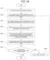
- FIG. 34 is a flowchart illustrating a method of measuring the depth of a keyhole
- FIG. 35 is a diagram schematically illustrating the trajectories of the processing laser beam and the measurement beam on the processing surface in a state in which the influence of the chromatic aberration of magnification is corrected by operating the second mirror;
- FIG. 36 is a diagram schematically illustrating a configuration of a laser processing apparatus according to modification 1 of the present disclosure
- FIG. 37 is a diagram schematically illustrating a configuration of a laser processing apparatus according to modification 4 of the present disclosure.
- FIG. 38 is a diagram illustrating an example of a laser processing apparatus according to the prior art.
- FIG. 1 is a diagram illustrating a configuration of a laser processing apparatus 1 according to embodiment 1 of the present disclosure.
- the laser processing apparatus 1 includes a processing head 2 , an optical interferometer 3 , a measurement processing unit 4 , a laser oscillator 5 , and a control unit 6 .
- the optical interferometer 3 emits a measurement beam 15 for OCT measurement, and the laser oscillator 5 oscillates a processing laser beam 11 for laser processing.
- the measurement beam 15 is input to the processing head 2 from a measurement beam inlet 9
- the processing laser beam 11 oscillated by the laser oscillator 5 is input to the processing head 2 from a processing beam inlet 10 .
- the processing laser beam 11 introduced from the processing beam inlet 10 passes through a dichroic mirror 12 , is reflected by a first mirror 13 , passes through a lens 14 , and is focused on a processing surface 19 on the surface of a workpiece 18 . Accordingly, a processing point 20 of the workpiece 18 is laser-processed. At this time, the processing point 20 irradiated with the processing laser beam 11 is melted, and a molten pool 21 is formed. Further, the molten metal is evaporated from the molten pool 21 , and a keyhole 22 is formed by the pressure of steam generated during the evaporation.
- the measurement beam 15 introduced from the measurement beam inlet 9 is converted into a parallel beam by a collimating lens 16 , is reflected by a second mirror 17 and the dichroic mirror 12 , is reflected by the first mirror 13 , passes through the lens 14 , and is focused on the processing point 20 on the surface of the workpiece 18 . Then, the measurement beam 15 is reflected by the bottom surface of the keyhole 22 , reaches the optical interferometer 3 along a propagation path, and generates an interference signal in the optical interferometer 3 due to optical interference with a reference beam that is not illustrated.
- the measurement processing unit 4 derives the depth of the keyhole 22 , that is, the penetration depth of the processing point 20 , from the interference signal.
- the penetration depth means a distance between the highest point of a melted portion of the workpiece 18 and the processing surface 19 .
- the wavelength of the processing laser beam 11 and the wavelength of the measurement beam 15 are different from each other.
- the dichroic mirror 12 has such characteristics that the dichroic mirror 12 transmits a light beam having the wavelength of the processing laser beam 11 and reflects a light beam having the wavelength of the measurement beam 15 .
- the first mirror 13 and the second mirror 17 are movable mirrors that can be rotated about two or more axes.
- each of the first mirror 13 and the second mirror 17 is a galvanometer mirror.
- the first mirror 13 and the second mirror 17 are connected to the control unit 6 via a first driver 7 and a second driver 8 , respectively, and are operated under control of the control unit 6 .
- the control unit 6 has a built-in memory 31 for holding processing data for performing desired processing on the workpiece 18 and correction data for performing correction, which will be described below.
- first mirror 13 and the second mirror 17 are configured to be rotatable about two or more axes as described above, and for example, can rotate about a rotation axis parallel to the paper surface.
- first mirror 13 and the second mirror 17 perform only a rotation operation about the rotation axis perpendicular to the paper surface.
- the present disclosure is not limited thereto, and the first mirror 13 and the second mirror 17 can also perform a rotation operation about another rotation axis.
- a measurement optical axis 23 of the measurement beam 15 coincides with a processing optical axis 24 of the processing laser beam 11 after being reflected by the dichroic mirror 12 .
- the processing optical axis 24 of the processing laser beam 11 coincides with a lens optical axis 25 that is the center of the lens 14 .
- an arrival position (irradiation position) of the processing laser beam 11 and the measurement beam 15 on the processing surface 19 of the workpiece 18 is described as a processing original point 26 .
- the original positions of the first mirror 13 and the second mirror 17 are positions where the processing laser beam 11 and the measurement beam 15 pass through the center of the lens 14 .
- the lens 14 is a lens for focusing the processing laser beam 11 and the measurement beam 15 on the processing point 20 .
- the lens 14 is an f ⁇ lens.
- the first mirror 13 and the lens 14 constitute a general optical scanning system including a galvanometer mirror and an f ⁇ lens. Therefore, by rotating the first mirror 13 from the original position by a predetermined operation amount, a position where the processing laser beam 11 reaches the processing surface 19 can be controlled.
- the operation amount of the first mirror 13 for irradiating a desired processing point 20 with the processing laser beam 11 can be uniquely set when a positional relationship between optical members constituting the processing head 2 and a distance from the lens 14 to the processing surface 19 are determined.
- a focal position where the processing laser beam 11 is most focused and the processing surface 19 are arranged to coincide with each other such that the processing by the processing laser beam 11 is performed most efficiently.
- the present disclosure is not limited thereto, and the distance from the lens 14 to the processing surface 19 may be determined to a predetermined distance according to a processing application.
- the position of the processing point 20 on the processing surface 19 can be scanned. Further, as the laser oscillator 5 is switched between an ON state and an OFF state under control of the control unit 6 , a predetermined position on the processing surface 19 can be laser-processed in a predetermined pattern within a scannable range of the processing laser beam 11 .
- FIG. 2 is a diagram illustrating the laser processing apparatus 1 in a state in which a first mirror 13 is operated from the original position. In FIG. 2 , it is assumed that the second mirror 17 is at the original position.
- the processing laser beam 11 and the measurement beam 15 reflected by the first mirror 13 travel on the same optical axis until the processing laser beam 11 and the measurement beam 15 reach the lens 14 .
- a deviation occurs in a traveling direction of the processing laser beam 11 and the measurement beam 15 , and the measurement beam 15 thus reaches a position different from the processing point 20 .
- an optical axis of the processing laser beam 11 is referred to as a processing optical axis 24 a
- an optical axis of the measurement beam 15 is referred to as a measurement optical axis 23 a.
- the chromatic aberration is an aberration generated since a general optical material including the lens 14 has a property that the refractive index varies depending on the wavelength of light.
- the chromatic aberration refers to a property that a focal position of a lens varies depending on the wavelength of light
- the chromatic aberration of magnification refers to a property that an image height on a focal plane varies depending on the wavelength of light.
- the deviation in the traveling direction of the processing laser beam 11 and the measurement beam 15 after the processing laser beam 11 and the measurement beam 15 pass through the lens 14 is caused by the chromatic aberration of magnification.
- the axial chromatic aberration also occurs.
- a distance between the collimating lens 16 and the measurement beam inlet 9 is adjusted, and the measurement beam 15 immediately after passing through the collimating lens 16 slightly diverges or converges from a parallel light state, so that it is possible to cope with the deviation.
- the measurement beam 15 reaches a position on the processing surface 19 which is farther than a position which the processing laser beam 11 reaches.
- the measurement beam 15 may reach a position that is closer to the processing original point 26 than the processing laser beam 11 due to a lens configuration of the lens 14 and a magnitude relationship between the wavelengths of the processing laser beam 11 and the measurement beam 15 .
- a beam having a longer wavelength reaches a position farther from the processing original point 26 .
- a method of making the lens 14 have properties of an achromatic lens exists as a method of correcting the chromatic aberration of magnification.
- a very advanced optical design technique is required, and large amounts of time and costs are required for designing the lens 14 . Therefore, in the present disclosure, as described below, the chromatic aberration of magnification is corrected with low costs by operating the second mirror 17 .
- FIG. 3 is a diagram illustrating the laser processing apparatus 1 in a state in which a deviation between arrival positions of the processing laser beam 11 and the measurement beam 15 due to the chromatic aberration of magnification is corrected.
- the second mirror 17 is operated by a predetermined operation angle (movement amount) from the original position. Accordingly, the processing optical axis 24 of the processing laser beam 11 and the measurement optical axis 23 of the measurement beam 15 are not coaxial from the dichroic mirror 12 to the lens 14 . However, after passing through the lens 14 , the processing laser beam 11 and the measurement beam 15 reach the same processing point 20 on the processing surface 19 . In FIG. 3 , the processing optical axis 24 a of the processing laser beam 11 passes through the same position as in FIG. 2 , and a measurement optical axis 23 b of the measurement beam 15 after being corrected by the operation of the second mirror 17 passes through a position different from the measurement optical axis 23 a as in FIG. 2 .
- a predetermined operation amount by which the second mirror 17 is operated from the original position is associated with an operation amount of the first mirror 13 on a one-to-one basis. Since the operation amount of the first mirror 13 is uniquely determined by the position of the processing point 20 at which the processing laser beam 11 (and the measurement beam 15 ) is irradiated, an operation amount of a second movable mirror is also uniquely determined by the position of the processing point 20 at which the measurement beam 15 is irradiated.
- the operation amount of the second mirror 17 from the original position is referred to as a correction angle in the following description. Hereinafter, a method of obtaining the correction angle will be described.
- the lens 14 which is an f ⁇ lens
- the focal length of the lens 14 is f
- the angle of a light beam incident on the lens 14 from the lens optical axis 25 is ⁇
- the distance (referred to as an image height) of a light beam passing through the lens 14 from an optical axis on an image plane is h
- the first mirror 13 has two rotating axes.
- the two axes are an x axis and a y axis
- an arrival position of the processing laser beam 11 on the processing surface 19 that is, the position (x, y) of the processing point 20 , is also determined.
- the scanning angle is uniquely determined by the position of the processing point 20
- the correction angle is uniquely determined by the position of the processing point 20 . That is, a relationship between the scanning angle and the correction angle is derived in advance for each position of the processing point 20 , and the second mirror 17 is operated only by the correction angle corresponding to the position of the processing point 20 during processing, so that the deviation of the measurement beam 15 due to the chromatic aberration of magnification can be corrected.
- FIG. 4 is a diagram illustrating trajectories of the processing laser beam 11 and the measurement beam 15 on the processing surface 19 when the surface of the workpiece 18 is scanned in a grid shape with operating only the first mirror 13 without operating the second mirror 17 in a state in which the processing surface 19 is viewed from the lens 14 side.
- a processing beam trajectory 28 which is a trajectory of the processing laser beam 11 is indicated by a solid line
- a measurement beam trajectory 27 which is a trajectory of the measurement beam 15 is indicated by a broken line.
- the chromatic aberration of magnification is not corrected since the second mirror 17 is not operated. Therefore, although the trajectories of the processing laser beam 11 and the measurement beam 15 coincide with each other in the vicinity of the processing original point 26 , the deviation between both trajectories increases as a distance from the processing original point 26 increases. Accordingly, while the processing beam trajectory 28 describes a grid-like pattern without distortion, the measurement beam trajectory 27 describes a distorted pincushion trajectory.
- the shape of the measurement beam trajectory 27 illustrated in FIG. 4 is an example, and the distortion shape of the measurement beam trajectory 27 can change depending on optical characteristics of the lens 14 .
- FIG. 4 illustrates a grid pattern of 4 ⁇ 4 squares at equal intervals as an example, the present disclosure is not limited thereto.
- the grid pattern for scanning may be set to a grid having a smaller number of squares, or a grid interval of a region requiring particularly accuracy may be reduced in relation to the chromatic aberration of magnification of the f ⁇ lens.
- a radial grid pattern may be set.
- an orthogonal grid pattern as illustrated in FIG. 4 is more preferable.
- FIG. 5 is a flowchart illustrating a first example of a method of creating correction number table data.
- step S 1 as in the processing beam trajectory 28 illustrated in FIG. 4 , a grid pattern in a range in which laser processing is performed on the processing surface 19 is set.
- step S 2 a two-dimensional beam profiler (not illustrated) is installed at a position of the grid pattern. At this time, the height position of the detection surface of the two-dimensional beam profiler is set to coincide with the processing surface 19 .
- step S 3 the scanning angle of the first mirror 13 is set such that the processing laser beam 11 reaches the grid point position.
- step S 4 the processing laser beam 11 is irradiated, and the arrival position where the processing laser beam 11 actually reaches the processing surface 19 is obtained using the two-dimensional beam profiler.
- step S 5 the measurement beam 15 is irradiated, and the arrival position where the measurement beam 15 actually reaches the processing surface 19 is obtained using the two-dimensional beam profiler.
- step S 6 the correction angle of the second mirror 17 is set with reference to the measurement result of the two-dimensional beam profiler such that the arrival position of the processing laser beam 11 obtained in step S 4 and the arrival position of the measurement beam 15 coincide with each other.
- step S 7 the set scanning angle and the set correction angle are stored in the memory 31 as data of a correction number table.
- step S 8 it is determined whether or not the data of the correction number table is acquired at all grid points of the grid pattern set in step S 1 . If the data is acquired at all the grid points (step S 8 : Yes), the process is terminated, otherwise (step S 8 : No), the process proceeds to step S 9 .
- step S 9 different grid point positions are set, and the process returns to step S 2 .
- FIG. 6 is a flowchart illustrating a second example of the method of creating correction number table data.
- a metal flat plate (hereinafter, referred to as a metal plate) or the like is installed as a temporary workpiece, and as in the processing beam trajectory 28 illustrated in FIG. 4 , a grid pattern in a range in which laser processing is performed is set on the processing surface 19 .
- step S 12 the scanning angle of the first mirror 13 is set such that the processing laser beam 11 reaches the grid point position.
- step S 13 the processing laser beam 11 is irradiated to make a minute hole in the surface of the metal plate. At this time, the output intensity and the irradiation time of the processing laser beam 11 are adjusted such that the workpiece 18 is penetrated. It is preferable that the diameter of the minute hole is about two to three times as large as a measurement resolution of the optical interferometer 3 .
- step S 14 the shape of the made minute hole is measured by the optical interferometer 3 .
- the optical interferometer 3 by operating the second mirror 17 to some extent from an angular position and scanning the measurement beam 15 , it is possible to measure a three-dimensional shape near the minute hole.
- step S 15 a correction angle at which the measurement beam 15 reaches the deepest part of the minute hole is obtained using the shape measurement data measured in step S 14 .
- step S 16 the correction angle obtained in step S 15 , the scanning angle at this time, and the correction number table data are stored in the memory 31 .
- step S 17 it is determined whether or not the data of the correction number table is acquired at all the grid points of the grid pattern set in step S 10 . If the data is acquired at all the grid points (step S 17 : Yes), the process is terminated, otherwise (step S 17 : No), the process proceeds to step S 18 .
- step S 18 different grid point positions are set, and the process returns to step S 12 .
- the correction number table data is obtained by the method described above. In the example illustrated in FIG. 4 , only the correction number table data at 16 grid points on the 4 ⁇ 4 grid pattern can be created. However, actually, it is preferable that the grid pattern is made finer, so that the correction number table data at more grid points is acquired. However, even when the very fine grid pattern data is used to create the correction number table data, the operation angle (scanning angle) of the first mirror 13 can be set to any value as long as the value belongs to an operation range of a mechanism, and thus the scanning angle may not coincide with the correction number table data. In such a case, it is necessary to obtain the correction angle by interpolating the correction number table data. A method of obtaining the correction angle by interpolating the correction number table data will be described below.
- a control unit controls the laser oscillator and the galvanometer mirror by using processing data in which an output indication value to a laser oscillator and a scanning angle data item are set for each processing point.
- the processing data is arranged in a chronological order, and the laser processing of the entire workpiece is performed by processing all the processing points on the surface of the workpiece in a chronological order.
- the correction angle is added as a data item of the processing data in addition to the output indication value to the laser oscillator, the position of the processing point, and the scanning angle.
- the processed data to which the correction angle is added as the data item in this manner is referred to as corrected processing data.
- FIG. 7 is a diagram illustrating a data configuration of the corrected processing data.
- the corrected processing data includes: as a set of data items, a data number k indicating an order of the processing data; a processing point position x k in the x direction; a processing point position y k in the y direction; laser output data L k indicating the output indication value to the laser oscillator; a scanning angle ⁇ x k of the first mirror 13 responsible for scanning in the x direction; a scanning angle ⁇ y k of the first mirror 13 responsible for scanning in the y direction; a correction angle ⁇ x k of the second mirror 17 responsible for correction of a measurement beam in the x direction; and a correction angle ⁇ y k of the second mirror 17 responsible for correction of a measurement beam in the y direction.
- the suffix k of each data item other than the data number k indicates that the data item corresponds to the data number k.
- the scanning angle in the corrected processed data is an example of a first indication value of the present disclosure
- the correction angle in the corrected processed data is an example of a second indication value of the present disclosure.
- FIG. 8 is a flowchart for illustrating a process of creating the corrected processing data.
- step S 21 the data number k attached to the area in the memory 31 where the processing data is stored is set to 0.
- step S 22 the laser output data L k and the processing point positions x k and y k are stored in the area of the data number k in the memory 31 .
- These values are set values set by a user of the laser processing apparatus 1 using a manipulation unit (a keyboard, a mouse, a touch panel, or the like) that is not illustrated, in order to realize desired laser processing.
- step S 23 the scanning angles ⁇ x k and ⁇ y k of the first mirror 13 are calculated from the processing point positions x k and y k stored in step S 22 , and are stored in the area of the data number k in the memory 31 .
- the focal length of the lens 14 is f
- a relational expression between the processing point position and the scanning angle, a correspondence number table, and the like may be set by the user in advance, and in this case, the scanning angle may be determined using the set items.
- step S 24 it is determined whether or not all the settings of the corrected processing data are completed. When all the settings of the corrected processing data are completed (step S 24 : Yes), the process is terminated, otherwise (step S 24 : No), the process proceeds to step S 25 .
- step S 25 the data number k to be referenced is increased by one, and the process returns to step S 22 . Accordingly, the corrected processing data is set for all the data numbers k.
- FIG. 9 is a diagram for illustrating a correction number table 34 schematically illustrating a data configuration of correction number table data.
- FIG. 9 is a diagram schematically illustrating data set for each grid point as a data point 32 at a grid point in the processing surface 19 .
- each data point 32 in FIG. 9 includes the position on the processing surface (processing point position), the scanning angle, and the correction angle.
- a correction data point 33 is a point corresponding to the processing original point 26 on the processing surface 19 .
- each data point in the correction number table 34 is indicated by a scanning angle ( ⁇ x, ⁇ y) for convenience.
- a data number in a direction corresponding to the scanning angle ⁇ x is i
- the data number in a direction corresponding to the scanning angle ⁇ y is j.
- the data point 32 holds ( ⁇ x i , ⁇ y j , ⁇ x ij , ⁇ y ij ) which is a set of a correction number table scanning angle ( ⁇ x i , ⁇ y j ) and a correction number table correction angle ( ⁇ x ij , ⁇ y ij ).
- FIG. 10 is a flowchart illustrating a correction angle setting process.
- step S 31 the data number k is set to “0”.
- step S 32 Yes
- step S 33 it is determined whether or not a data item including the same scanning angle as the correction angle set by the user exists in the correction number table 34 .
- step S 33 since a data item including the scanning angle which is exactly the same as the correction angle set by the user exists, the corresponding correction number table correction angle is set as the correction angle as it is.
- step S 34 the correction angle ( ⁇ x k , ⁇ y k ) is set by performing interpolation processing using data of four closest points in the correction number table data with respect to the scanning angle ( ⁇ x k , ⁇ y k ) set by the user. Details of step S 34 will be described below.
- step S 35 the correction angle ( ⁇ x k , ⁇ y k ) set in step S 33 or step S 34 is stored in the area of the data number k of the processing data in the memory 31 .
- step S 36 it is determined whether or not the correction angles are set for all of the processing data stored in the memory 31 .
- Step S 36 it is determined whether or not the correction angles are set for all of the processing data stored in the memory 31 .
- step S 37 the data number k to be referenced is increased by one, and the process returns to step S 32 . Accordingly, the corrected processing data is set for all the data numbers k.
- Step S 34 (interpolation processing) in FIG. 10 will be described in detail.
- the scanning angle ( ⁇ x k , ( ⁇ y k ) set by the user does not coincide with any of the correction number table scanning angle ( ⁇ x i , ⁇ y j ) in the data point 32 .
- FIG. 11 is a diagram illustrating a relationship between a scanning angle X ( ⁇ x k , ⁇ y k ) and a surrounding correction data point when the scanning angle X ( ⁇ x k , ⁇ y k ) set as processing data by the user does not coincide with the correction number table scanning angle at any data point 32 on the correction number table 34 .
- the point corresponding to the scanning angle X ( ⁇ x k , ⁇ y k ) is located in a grid formed by four points including the correction data point A (( ⁇ x i , ⁇ y j , ⁇ x ij , ⁇ y ij ), the correction data point B ( ⁇ x i+1 , ⁇ y j , ⁇ x i+1j , ⁇ y i+1j ), the correction data point C ( ⁇ x i , ⁇ y j+1 , ⁇ x ij+1 , ⁇ y ij+1 ), and the correction data point D ( ⁇ x i+1 , ⁇ y j+1 , ⁇ x i+1j+1 , ⁇ y i+1j+1 ).
- Equations (1) and (2) are obtained by Equations (3) to (7).
- E ( ⁇ x k ⁇ x i )( ⁇ y k ⁇ y j ) (3)
- F ( ⁇ x i+1 ⁇ x k )(( ⁇ y k ⁇ y j ) (4)
- G ( ⁇ x k ⁇ x i )( ⁇ y j+1 ⁇ y k ) (5)
- H ( ⁇ x i+1 ⁇ x k )( ⁇ y j+1 ⁇ y k ) (6)
- J ( ⁇ x i+1 ⁇ x i )( ⁇ y j+1 ⁇ y j ) (7)
- the correction angle can be derived by the interpolation processing based on the scanning angle set by the user.
- the correction angle after the interpolation processing is an example of a third operation amount according to the present disclosure.
- a linear interpolation method is used as an interpolation method.
- other known two-dimensional interpolation methods spline interpolation, quadratic surface approximation, and the like
- a high-order approximate continuous curved surface for the correction angle with respect to the scanning angle may be calculated in advance from the correction number table correction angle ( ⁇ x ij , ⁇ y ij ) on the correction number table 34 , and the correction angle corresponding to the scanning angle may be derived.
- FIG. 12 is a flowchart illustrating the laser processing process.
- step S 41 the data number k is set to 0.
- step S 42 the laser output data L k , the scanning angle ⁇ x k , ⁇ y k , and the correction angles ⁇ x k , ⁇ y k corresponding to the data number k are read.
- step S 43 the control unit 6 operates the first mirror 13 via the first driver 7 using the scanning angle ⁇ x k and ⁇ y k as an operation amount, and operates the second mirror 17 via the second driver 8 using the correction angle ⁇ x k and ⁇ y k as an operation amount.
- step S 44 the control unit 6 transmits the laser output data L k as a laser output value to the laser oscillator 5 and causes the processing laser beam 11 to oscillate.
- step S 45 it is determined whether or not the laser processing corresponding to all the data numbers k stored in the memory 31 is completed.
- step S 45 : Yes the process is terminated, otherwise (step S 45 : No), the process proceeds to step S 46 .
- step S 46 the data number k to be referenced is increased by one, and the process returns to step S 42 . Accordingly, the processing is performed for all the data numbers k.
- FIG. 13 is a flowchart illustrating a keyhole depth measurement process.
- step S 51 before the laser processing process described with reference to FIG. 12 starts, position data of the processing surface 19 of the unprocessed workpiece 18 is obtained.
- step S 52 the measurement processing unit 4 generates an optical interference signal corresponding to an optical path difference between the reference beam and the measurement beam 15 reflected back from the keyhole 22 in the optical interferometer 3 .
- step S 53 the measurement processing unit 4 derives the depth (penetration depth) of the keyhole 22 using the optical interference signal.
- the derived depth of the keyhole 22 is stored in the memory 31 .
- step S 54 it is determined whether or not to terminate the keyhole depth measurement process.
- the process proceeds to step S 55 ; otherwise (Step S 54 : No), the process returns to step S 52 .
- step S 55 the control unit 6 outputs, to the measurement processing unit 4 , an instruction to terminate the keyhole depth measurement process.
- Instructions to start the keyhole depth measurement process and terminate the keyhole depth measurement process may not be performed by the control unit 6 , but may be performed by using the manipulation unit or the like, which is not illustrated, of the user.
- the laser processing apparatus 1 has: the laser oscillator 5 that oscillates the processing laser beam at the processing point where the workpiece is to be processed; an optical interferometer 3 that emits the measurement beam to the processing point and generates an optical interference intensity signal based on interference caused by an optical path difference between the measurement beam and the reference beam reflected at the processing point; a first mirror 13 that changes the traveling directions of the processing laser beam and the measurement beam; the second mirror 17 that changes an incident angle of the measurement beam to the first mirror 13 ; a lens 14 that focuses the processing laser beam and the measurement beam on the processing point; a memory 31 that stores the corrected processing data corrected in advance to eliminate a deviation between irradiation positions of the processing laser beam and the measurement beam caused by chromatic aberration of the lens on the surface of the workpiece, the corrected processing data being for processing the workpiece; the control unit that controls the laser oscillator 5 , the first mirror 13 , and the second mirror 17 based on the corrected processing data; and the measurement processing unit
- FIG. 14 is a diagram illustrating the trajectories of the processing laser beam 11 and the measurement beam 15 on the processing surface 19 in a state in which influence of the chromatic aberration of magnification is corrected due to operation of the second mirror 17 .
- the processing beam trajectory 28 which is a trajectory of the processing laser beam 11
- the measurement beam trajectory 27 a which is a trajectory of the measurement beam 15
- the respective grid points coincide with each other.
- the second mirror 17 which is a galvanometer mirror is used to change an optical axis direction of the measurement beam 15
- the present disclosure is not limited thereto.
- a configuration may be adopted which is installed between the measurement beam inlet 9 and the dichroic mirror 12 and can change an optical axis direction of the measurement beam 15 based on control of the control unit 6 .
- FIG. 15 is a diagram illustrating a modification of the second mirror 17 .
- a second mirror 35 as the second mirror 17 is fixed between the measurement beam inlet 9 and the dichroic mirror 12 and the measurement beam inlet 9 is provided with a movable stage 36 for moving a measurement beam emission end.
- the measurement beam emission end of the measurement beam inlet 9 is disposed be located at a focal point of the second mirror 35 , becomes a parallel beam after being reflected by the second mirror 35 , and travels toward the dichroic mirror 12 .
- the movable stage 36 is operated based on control of the control unit 6 via a stage driver 37 .
- An operation direction of the movable stage 36 is a two-axis direction perpendicular to the measurement optical axis 23 .
- the angle of the measurement optical axis 23 from the second mirror 35 to the dichroic mirror 12 is changed by operating the movable stage 36 , in the above-described embodiment, the same effect as the second mirror 17 employing the galvanometer mirror can be obtained.
- a microelectromechanical systems (MEMS) mirror or the like may be employed as the second mirror 17 .
- the laser processing apparatus and the laser processing method of the present disclosure can be applied to a laser processing apparatus that performs laser processing on automobiles, electronic components, and the like.
- a configuration of the laser processing apparatus 1 according to the embodiment of the present disclosure will be described with reference to FIG. 16 .
- FIG. 16 is a diagram schematically illustrating a configuration of the laser processing apparatus 1 according to the present embodiment.
- the laser processing apparatus 1 includes a processing head 2 , an optical interferometer 3 , a measurement processing unit 4 , a laser oscillator 5 , a control unit 6 , a first driver 7 , a second driver 8 , and a third driver 41 .
- the optical interferometer 3 emits the measurement beam 15 for OCT measurement.
- the emitted measurement beam 15 is input to the processing head 2 from the measurement beam inlet 9 .
- the measurement beam inlet 9 is installed on the second mirror 17 .
- the laser oscillator 5 oscillates the processing laser beam 11 for laser processing.
- the oscillated processing laser beam 11 is input to the processing head 2 from the processing beam inlet 10 .
- the processing laser beam 11 input to the processing head 2 passes through the dichroic mirror 12 , is reflected by the first mirror 13 , passes through the lens 14 , and is focused on the processing surface 19 on the surface of the workpiece 18 . Accordingly, a processing point 20 of the workpiece 18 is laser-processed. At this time, the processing point 20 irradiated with the processing laser beam 11 is melted, and a molten pool 21 is formed. Further, the molten metal is evaporated from the molten pool 21 , and a keyhole 22 is formed by the pressure of steam generated during the evaporation.
- the measurement beam 15 input to the processing head 2 is converted into a parallel beam by the collimating lens 16 , is reflected by the second mirror 17 , and then passes through a beam shift mechanism 38 . Thereafter, the measurement beam 15 is reflected by the dichroic mirror 12 , is reflected by the first mirror 13 , passes through the lens 14 , and is then focused on the processing point 20 on the surface of the workpiece 18 . Then, the measurement beam 15 is reflected by the bottom surface of the keyhole 22 , reaches the optical interferometer 3 along a propagation path, and generates an interference signal in the optical interferometer 3 due to optical interference with a reference beam that is not illustrated.
- the measurement processing unit 4 measures the depth of the keyhole 22 , that is, the penetration depth of the processing point 20 , from the interference signal.
- the penetration depth means a distance between the processing surface 19 and the highest point of the melted portion of the workpiece 18 .
- the wavelength of the processing laser beam 11 and the wavelength of the measurement beam 15 are different from each other.
- the dichroic mirror 12 has a property of transmitting a beam having the wavelength of the processing laser beam 11 and reflecting a beam having the wavelength of the measurement beam 15 .
- the wavelength of the processing laser beam 11 is 1064 nm.
- the wavelength of the measurement beam 15 is 1300 nm.
- the first mirror 13 and the second mirror 17 are movable mirrors that can rotate about two or more axes.
- the first mirror 13 and the second mirror 17 are, for example, galvanometer mirrors.
- the first mirror 13 and the second mirror 17 are connected to the control unit 6 via the first driver 7 and the second driver 8 , respectively, and are operated under the control of the control unit 6 .
- the first driver 7 operates the first mirror 13 based on an instruction from the control unit 6 .
- the second driver 8 operates the second mirror 17 based on the instruction from the control unit 6 .
- the control unit 6 has a memory 31 .
- the memory 31 stores processing data for performing desired processing on the workpiece 18 and correction data for performing correction which will be described below.
- FIG. 16 illustrates, as an example, only rotation of each of the first mirror 13 and the second mirror 17 about a rotation axis in the y direction (see a dotted line and a two-way arrow in the drawing).
- each of the first mirror 13 and the second mirror 17 is configured to be rotatable about two or more axes as described above. Therefore, each of the first mirror 13 and the second mirror 17 can also perform a rotation operation about, for example, a rotation axis in the x direction.
- each of the first mirror 13 and the second mirror 17 performs a rotation operation about the rotation axis in the y direction.
- the measurement optical axis 23 of the measurement beam 15 coincides with the processing optical axis 24 of the processing laser beam 11 after the measurement beam 15 is reflected by the dichroic mirror 12 .
- the processing optical axis 24 of the processing laser beam 11 coincides with the lens optical axis 25 that is the center of the lens 14 when the processing laser beam 11 passes through the lens 14 after being reflected by the first mirror 13 .
- the positions (referred to as an irradiation position) at which the processing laser beam 11 and the measurement beam 15 having passed through the center of the lens 14 reach the processing surface 19 of the workpiece 18 are referred to as a “processing original point 26 (see FIG. 17 ).” That is, the original positions of the first mirror 13 and the second mirror 17 are positions at which the processing laser beam 11 and the measurement beam 15 pass through the center of the lens 14 .
- the lens 14 is a lens for focusing the processing laser beam 11 and the measurement beam 15 on the processing point 20 .
- the lens 14 is, for example, an f ⁇ lens.
- the first mirror 13 and the lens 14 constitute a general optical scanning system including a galvanometer mirror and an f ⁇ lens. Therefore, as the first mirror 13 is rotated by a predetermined angle from the original position, the position where the processing laser beam 11 reaches the processing surface 19 can be controlled.
- an angle by which the first mirror 13 is rotated from the original position thereof is referred to as an “operation amount of the first mirror 13 ”.
- the operation amount of the first mirror 13 for irradiating a desired processing point 20 with the processing laser beam 11 can be uniquely set when a positional relationship between optical members constituting the processing head 2 and a distance from the lens 14 to the processing surface 19 are determined.
- the distance from the lens 14 to the processing surface 19 is a distance in which the focal position where the processing laser beam 11 is most focused coincides with the processing surface 19 such that the processing with the processing laser beam 11 is performed most efficiently.
- the present disclosure is not limited thereto, and the distance from the lens 14 to the processing surface 19 may be determined as a predetermined distance according to a processing application.
- the position of the processing point 20 can be scanned on the processing surface 19 . Further, as the laser oscillator 5 is turned on and off under the control of the control unit 6 , a predetermined position on the processing surface 19 can be laser-processed in a predetermined pattern within a scannable range of the processing laser beam 11 .
- the beam shift mechanism 38 is a mechanism for parallel translation of the measurement optical axis 23 of the measurement beam 15 in two or more axes.
- the beam shift mechanism 38 is a parallel translation stage.
- the beam shift mechanism 38 is configured to perform the parallel translation in two or more axes in a direction (see the xy axis and a linear two-way arrow in the drawing) perpendicular to the measurement optical axis 23 of the measurement beam 15 when the second mirror 17 is located at the original position.
- the beam shift mechanism 38 is connected to the control unit 6 via the third driver 41 , and is operated based on the control of the control unit 6 .
- the third driver 41 operates the beam shift mechanism 38 based on an instruction from the control unit 6 .
- the beam shift mechanism 38 is provided with a first lens 39 and a second lens 40 .
- a distance between a principal point of the first lens 39 and a principal point of the second lens 40 is set to a distance obtained by adding the focal lengths of the two lenses.
- the focal length of the first lens 39 and the focal length of the second lens 40 are the same.
- the measurement optical axis 23 of the measurement beam 15 coincides with the processing optical axis 24 of the processing laser beam 11 after the measurement beam 15 reflected by the dichroic mirror 12 .
- FIG. 17 is a diagram schematically illustrating the laser processing apparatus 1 in a state in which the first mirror 13 is operated from the original position. In FIG. 17 , it is assumed that the second mirror 17 is located at the original position.
- the processing laser beam 11 and the measurement beam 15 reflected by the first mirror 13 travel on the same optical axis until the processing laser beam 11 and the measurement beam 15 reach the lens 14 .
- a deviation occurs in the traveling direction of the processing laser beam 11 and the measurement beam 15 . That is, as illustrated in FIG. 17 , the processing optical axis 24 a , which is an optical axis of the processing laser beam 11 , and the measurement optical axis 23 a , which is an optical axis of the measurement beam 15 , are shifted. Therefore, the measurement beam 15 reaches a position different from the processing point 20 .
- the chromatic aberration is an aberration generated since a general optical material including the lens 14 has a property that the refractive index varies depending on the wavelength of light.
- the chromatic aberration refers to a property that the focal position of a lens differs depending on the wavelength of light.
- the chromatic aberration of magnification refers to a property that the image height on the focal plane varies depending on the wavelength of light.
- the deviation the processing laser beam 11 (the processing optical axis 24 a ) and the measurement beam 15 (the measurement optical axis 23 a ) in the traveling direction after the processing laser beam 11 and the measurement beam 15 pass through the lens 14 is caused by the chromatic aberration of magnification.
- the axial chromatic aberration also occurs at the same time.
- a distance between the collimating lens 16 and the measurement beam inlet 9 is adjusted, and the measurement beam 15 immediately after passing through the collimating lens 16 slightly diverges or converges from a parallel light state, so that it is possible to cope with the deviation.
- a position where the measurement beam 15 reaches the processing surface 19 is farther than a position where the processing laser beam 11 reaches the processing surface 19 .
- the measurement beam 15 may reach a position that is closer to the processing original point 26 than the processing laser beam 11 due to a lens configuration of the lens 14 and a magnitude relationship between the wavelengths of the processing laser beam 11 and the measurement beam 15 .
- a beam having a longer wavelength reaches a position farther from the processing original point 26 .
- a method of making the lens 14 have a property of an achromatic lens exists as a method of correcting the chromatic aberration of magnification.
- a very advanced optical design technique is required, and large amounts of time and costs are required for designing the lens 14 . Therefore, in the present embodiment, as described below, the chromatic aberration of magnification is corrected at a low cost by operating the second mirror 17 .
- FIG. 18 is a diagram schematically illustrating the laser processing apparatus 1 in a state in which the deviation between the arrival positions of the processing laser beam 11 and the measurement beam 15 due to the chromatic aberration of magnification is corrected.
- the second mirror 17 is operated from the original position by a predetermined operation amount (referred to as an operation angle). Accordingly, as illustrated in FIG. 18 , while the processing laser beam 11 and the measurement beam 15 move from the dichroic mirror 12 to the lens 14 , the processing optical axis 24 of the processing laser beam 11 and the measurement optical axis 23 of the measurement beam 15 are not coaxial. However, after passing through the lens 14 , the processing laser beam 11 and the measurement beam 15 reach the same position on the processing surface 19 , that is, the processing point 20 .
- a predetermined operation amount referred to as an operation angle
- the processing optical axis 24 a of the processing laser beam 11 passes through the same position as the processing optical axis 24 a illustrated in FIG. 17 .
- the measurement optical axis 23 b of the measurement beam 15 corrected by operating the second mirror 17 passes through a position different from the measurement optical axis 23 a illustrated in FIG. 17 .
- the operation amount (that is, an angle by which the second mirror 17 is rotated from the original position thereof) of the second mirror 17 is associated with the operation amount of the first mirror 13 on a one-to-one basis. Since the operation amount of the first mirror 13 is uniquely determined by the position of the processing point 20 at which the processing laser beam 11 (and the measurement beam 15 ) is irradiated, the operation amount of the second mirror 17 is also uniquely determined by the position of the processing point 20 at which the measurement beam 15 is irradiated. Hereinafter, the operation amount of the second mirror 17 is also described as a “correction angle”, and a method of obtaining the correction angle will be described.
- the arrival position of the processing laser beam 11 on the processing surface 19 that is, the position (x, y) of the processing point 20 , is also determined.
- the scanning angle is uniquely determined by the position of the processing point 20
- the correction amount is also uniquely determined by the position of the processing point 20 . That is, a relationship between the scanning angle and the correction amount is calculated in advance for each position of a certain processing point 20 , and the second mirror 17 is operated by the correction amount corresponding to the position of the processing point 20 during processing, so that the deviation of the measurement beam 15 due to the chromatic aberration of magnification can be corrected.
- the processing optical axis 24 a of the processing laser beam 11 and the measurement optical axis 23 b of the measurement beam 15 do not coincide with each other.
- a processing speed of the processing laser beam 11 When the scanning speed (hereinafter, referred to as a processing speed) of the processing laser beam 11 is low, a direction in which the keyhole 22 is formed coincides with the processing optical axis 24 a of the processing laser beam 11 , and thus the measurement beam 15 is incident obliquely to the direction in which the keyhole 22 is formed. Accordingly, a case occurs in which the measurement beam 15 cannot reach the bottom of the keyhole 22 . As a result, measurement accuracy of the depth of the keyhole 22 deteriorates.
- FIG. 19 schematically illustrates an example of a state in which the keyhole 22 is formed when the processing speed is high.
- the processing optical axis 24 a of the processing laser beam 11 moves in a positive direction of the x axis
- the keyhole 22 is formed in a state in which a keyhole forming axis 42 is inclined in a processing direction (the positive direction of the x axis) with the processing point 20 as a starting point. Therefore, even in a state in which the deviation between the arrival positions of the processing laser beam 11 and the measurement beam 15 due to the chromatic aberration of magnification is corrected, a case may occur in which the measurement beam 15 does not reach the bottom of the keyhole 22 . As a result, measurement accuracy of the depth of the keyhole 22 deteriorates.
- the spot diameter of the processing laser beam 11 at the processing point 20 is reduced to, for example, 50 ⁇ m or less. Therefore, the diameter of the generated keyhole 22 is also reduced, and the deviation between an angle of the keyhole forming axis 42 of the keyhole 22 and an angle of the measurement optical axis 23 b of the measurement beam 15 is a factor that causes great deterioration of measurement accuracy of the depth of the keyhole 22 .
- the beam shift mechanism 38 by operating the beam shift mechanism 38 , the angle of the measurement optical axis 23 b of the measurement beam 15 is corrected, so that the measurement optical axis 23 b and the keyhole forming axis 42 coincide with each other.
- FIG. 20 is a diagram schematically illustrating the laser processing apparatus 1 in a state in which the angle deviation between the keyhole forming axis 42 and the measurement optical axis 23 b of the measurement beam 15 illustrated in FIG. 18 is corrected.
- the beam shift mechanism 38 is operated from an original position by a predetermined operation amount (which may be referred to as an operation distance). Accordingly, while the measurement beam 15 and the processing laser beam 11 move from the dichroic mirror 12 to the lens 14 , the measurement optical axis 23 of the measurement beam 15 is shifted in parallel to the processing optical axis 24 of the processing laser beam 11 . However, after passing through the lens 14 , the processing laser beam 11 and the measurement beam 15 reach the same processing point 20 on the processing surface 19 .
- a predetermined operation amount which may be referred to as an operation distance
- the processing optical axis 24 a of the processing laser beam 11 passes through the same position as the processing optical axis 24 a illustrated in FIG. 18 .
- a measurement optical axis 23 c is obtained by correcting the measurement optical axis 23 b illustrated in FIG. 18 by operating the beam shift mechanism 38 .
- An angle of the measurement optical axis 23 c illustrated in FIG. 20 is different from the angle of the measurement optical axis 23 b illustrated in FIG. 18 , and coincides with an angle of the keyhole forming axis 42 of the keyhole 22 .
- a predetermined operation amount (hereinafter, referred to as a correction movement amount) for operating the beam shift mechanism 38 from the original position is associated with the operation amount and the processing speed of the first mirror 13 . Since the operation amount and the processing speed of the first mirror 13 are uniquely determined by the position of the processing point 20 where the processing laser beam 11 (and the measurement beam 15 ) is irradiated, the correction movement amount is also uniquely determined by the position of the processing point 20 where the measurement beam 15 is irradiated.
- a relationship between the scanning angle and the correction movement amount is calculated in advance for each position of the processing point 20 , and the beam shift mechanism 38 is operated by the correction movement amount corresponding to the position of the processing point 20 during the processing, so that the angle deviation between the keyhole forming axis 42 and the measurement optical axis 23 b illustrated in FIG. 18 can be corrected.
- the first correction number table data is data indicating a correspondence between the scanning angle and the correction angle for each processing point 20 .
- the first correction number table data may be referred to as correction number table data for a correction angle.
- FIG. 21 is a diagram schematically illustrating the trajectories of the processing laser beam 11 and the measurement beam 15 on the processing surface 19 when the surface (that is, the processing surface 19 ) of the workpiece 18 is scanned in a grid pattern by operating only the first mirror 13 without operating the second mirror 17 .
- FIG. 21 illustrates a state in which the processing surface 19 is viewed from the lens 14 side.
- the processing beam trajectory 28 which is a trajectory of the processing laser beam 11
- the measurement beam trajectory 27 which a trajectory of the measurement beam 15
- the second mirror 17 since the second mirror 17 is not operated, the chromatic aberration of magnification is not corrected. Therefore, although the trajectories of the processing laser beam 11 and the measurement beam 15 coincide with each other in the vicinity of the processing original point 26 , the deviation therebetween increases as a distance from the processing original point 26 increases. Accordingly, while the processing beam trajectory 28 describes a grid-like pattern without distortion, the measurement beam trajectory 27 describes a distorted pincushion trajectory.
- the shape of the measurement beam trajectory 27 illustrated in FIG. 21 is an example, and the distortion shape of the measurement beam trajectory 27 can change depending on optical characteristics of the lens 14 .
- the amount of deviation between the positions corresponding to the processing beam trajectory 28 and the measurement beam trajectory 27 also depends on optical characteristics and an optical design of the lens 14 .
- a deviation of 0.2 mm to 0.4 mm occurs near the outermost periphery of the processing surface area.
- the diameter of the keyhole 22 (for example, see FIG. 16 ) generated by irradiating the processing point 20 with the processing laser beam 11 is as small as about 0.03 mm to 0.2 mm depending on power and quality of the processing laser beam. For this reason, the measurement beam 15 does not reach the bottom surface of the keyhole 22 due to a positional deviation between the processing laser beam 11 and the measurement beam 15 caused by the chromatic aberration of the lens 14 , and thus a correct penetration depth cannot be measured.
- FIG. 21 illustrates a grid pattern of 4 ⁇ 4 squares at equal intervals as an example, the present disclosure is not limited thereto.
- the grid pattern for scanning may be set to a grid having a finer square count or may have a reduced grid interval of a region requiring particularly high accuracy in relation to the chromatic aberration of magnification of the f ⁇ lens.
- a radial grid pattern may be set.
- the orthogonal grid pattern illustrated in FIG. 21 is more preferable.
- FIG. 22 is a flowchart illustrating the first example of the method of creating the first correction number table data.
- step S 1 the control unit 6 sets a grid pattern (for example, the processing beam trajectory 28 illustrated in FIG. 21 ) in a range in which the laser processing is performed on the processing surface 19 of the workpiece 18 .
- a grid pattern for example, the processing beam trajectory 28 illustrated in FIG. 21
- control unit 6 selects one grid point from a plurality of grid points included in the grid pattern.
- step S 2 the control unit 6 sets a two-dimensional beam profiler (not illustrated) at the selected grid point. At this time, the height position of a detection surface of the two-dimensional beam profiler is set to coincide with the processing surface 19 .
- step S 3 the control unit 6 sets the scanning angle of the first mirror 13 such that the processing laser beam 11 reaches the selected grid point.
- step S 4 The control unit 6 obtains a position (hereinafter, referred to as an arrival position of the processing laser beam 11 ) where the processing laser beam 11 actually reaches the processing surface 19 , by irradiating the processing laser beam 11 and using the two-dimensional beam profiler.
- step S 5 the control unit 6 obtains a position (hereinafter, referred to as an arrival position of the measurement beam 15 ) where the measurement beam 15 actually reaches the processing surface 19 , by irradiating the measurement beam 15 and using the two-dimensional beam profiler.
- step S 6 the control unit 6 sets the correction angle of the second mirror 17 with reference to the measurement result of the two-dimensional beam profiler such that the arrival position of the processing laser beam 11 coincides with the arrival position of the measurement beam 15 .
- step S 7 the control unit 6 stores, in the memory 31 , the scanning angle set in step S 3 and the correction angle set in step S 6 as the correction number table data.
- step S 8 the control unit 6 determines whether or not the correction number table data is stored at all the grid points of the grid pattern.
- step S 8 : YES the flow is terminated.
- step S 9 the flow proceeds to step S 9 .
- step S 9 the control unit 6 selects one new grid point (that is, a grid point at which the correction number table data is not stored). Thereafter, the flow returns to step S 2 .
- FIG. 23 is a flowchart illustrating the second example of the method of creating the first correction number table data.
- a metal flat plate (hereinafter, referred to as a metal plate) is used as a temporary workpiece.
- step S 11 the control unit 6 sets a grid pattern (for example, the processing beam trajectory 28 illustrated in FIG. 21 ) in a range in which the laser processing is performed on the processing surface 19 of the metal plate. Further, the control unit 6 selects one grid point from a plurality of grid points included in the grid pattern.
- a grid pattern for example, the processing beam trajectory 28 illustrated in FIG. 21
- step S 12 the control unit 6 sets the scanning angle of the first mirror 13 such that the processing laser beam 11 reaches the selected grid point.
- step S 13 the control unit 6 irradiates the selected grid point with the processing laser beam 11 , and makes a minute hole in the surface of the metal plate.
- the output intensity and the irradiation time of the processing laser beam 11 are adjusted such that the processing laser beam 11 passes through the metal plate.
- the diameter of the minute hole formed herein is about two to three times as large as the measurement resolution of the optical interferometer 3 .
- step S 14 the control unit 6 causes the optical interferometer 3 to measure the shape of the formed minute hole. At this time, a three-dimensional shape near the minute hole can be measured by operating the second mirror 17 from the original position to some extent and scanning the measurement beam 15 .
- step S 15 the control unit 6 obtains the correction angle of the second mirror 17 at which the measurement beam 15 can reach the deepest part of the minute hole, by using data indicating the result measured in step S 14 .
- step S 16 the control unit 6 stores, in the memory 31 , the scanning angle set in step S 12 and the correction angle obtained in step S 15 as the correction number table data.
- step S 17 the control unit 6 determines whether or not the correction number table data is stored at all the grid points of the grid pattern.
- step S 17 : YES the flow is terminated.
- step S 18 the flow proceeds to step S 18 .
- step S 18 the control unit 6 selects one new grid point (that is, a grid point at which correction number table data is not stored). Thereafter, the flow returns to step S 12 .
- the first correction number table data is obtained.
- the grid pattern set in step S 1 or step S 11 is the 4 ⁇ 4 grid pattern illustrated in FIG. 21 . Therefore, it is preferable that more correction number table data is created by setting a grid-like pattern including 16 or more grid points.
- the scanning angle of the first mirror 13 can be set to any value within an operation range of a mechanism, and thus the scanning angle may not coincide with the correction number table data. In such a case, it is necessary to obtain the correction angle by interpolating the correction number table data. A method of obtaining a correction angle by interpolating the correction number table data will be described below.
- the second correction number table data is data indicating a correspondence between the scanning angle and the correction movement amount.
- the correction movement amount corresponds to the position (hereinafter, referred to as a processing position) and the processing speed of the processing point 20 .
- the second correction number table data is created after the above-described first correction number table data is created.
- the second correction number table data is created separately for the processing position and the processing speed.
- the correction movement amount related to the processing position is referred to as a “position correction movement amount”
- the correction movement amount related to the processing speed is referred to as a “speed correction movement amount”.
- correction number table data of the position correction movement amount and correction number table data of the speed correction movement amount are created as the second correction number table data.
- FIG. 24 is a flowchart illustrating an example of the method of creating the correction number table data of the position correction movement amount.
- a metal flat plate (hereinafter, referred to as a metal plate) is used as a temporary workpiece.
- step S 21 the control unit 6 sets a grid pattern (for example, the processing beam trajectory 28 illustrated in FIG. 21 ) in a range in which the laser processing is performed on the processing surface 19 of the metal plate. Further, the control unit 6 selects one grid point from a plurality of grid points included in the grid pattern.
- a grid pattern for example, the processing beam trajectory 28 illustrated in FIG. 21
- step S 22 the control unit 6 sets the scanning angle of the first mirror 13 such that the processing laser beam 11 reaches the selected grid point.
- step S 23 the control unit 6 sets the correction angle of the second mirror 17 such that the measurement beam 15 reaches the selected grid point.
- the correction angle is a value stored as the above-described first correction number table data.
- step S 24 the control unit 6 makes a minute hole in the surface of the metal plate by irradiating the selected grid point with the processing laser beam 11 .
- the output intensity and the irradiation time of the processing laser beam 11 are adjusted such that the processing laser beam 11 passes through the metal plate.
- the diameter of the minute hole formed herein is about two to three times as large as the measurement resolution of the optical interferometer 3 .
- step S 25 the control unit 6 obtains the position correction movement amount, at which the depth of the keyhole 22 is maximized, by scanning an angle of the measurement optical axis 23 to the beam shift mechanism 38 .
- step S 26 the control unit 6 stores, in the memory 31 , the scanning angle set in step S 22 and the position correction movement amount obtained in step S 25 in the memory 31 as the correction number table data.
- step S 27 the control unit 6 determines whether or not the correction number table data is stored at all the grid points of the grid pattern.
- step S 27 : YES the flow is terminated.
- step S 27 : NO the flow proceeds to step S 28 .
- step S 28 the control unit 6 selects one new grid point (that is, a grid point at which the correction number table data is not stored). Thereafter, the flow returns to step S 22 .
- the correction number table data for the position correction movement amount is obtained.
- the grid pattern set in step S 21 is the same as the grid pattern set in the above-described method of creating the first correction number table data. Therefore, when the scanning angle does not coincide with the correction number table data, the position correction movement amount can be obtained by interpolating the correction number table data in the same manner as that described in the method of creating the first correction number table data.
- the correction number table data for the position correction movement amount and the first correction number table data are set as a correction number table of the processing position.
- FIG. 25 is a flowchart illustrating an example of the method of creating the correction number table data of the speed correction movement amount.
- a metal plate is used as a temporary workpiece.
- step S 31 the control unit 6 sets the scanning angle of the first mirror and the correction angle of the second mirror passing through a scanning line including the processing original point 26 (see FIGS. 17 and 18 ).
- a scanning line on the x axis passing through the processing original point 26 is used as the scanning line, and values stored as the first correction number table data are used as the scanning angle and the correction angle.
- step S 32 the control unit 6 sets a range of the processing speed. For example, the control unit 6 sets a range from the maximum value to the minimum value of the processing speed included in the processing data for processing the workpiece 18 to a range of the processing speed.
- step S 33 the control unit 6 sets a range of the correction movement amount.
- the control unit 6 sets a range in which the angle of the measurement optical axis 23 of the measurement beam 15 incident on the processing point 20 is ⁇ 10 deg in the scanning direction to a range of the correction movement amount.
- step S 34 the control unit 6 sets an initial value of the processing speed.
- the minimum value of the range of the processing speed is set as the initial value of the processing speed.
- step S 35 the control unit 6 sets an initial value of the correction movement amount.
- the minimum value of the range of the correction movement amount is set as the initial value of the correction movement amount.
- step S 36 the control unit 6 simultaneously scans the scanning line with the processing laser beam 11 and the measurement beam 15 at the set processing speed, and measures the depth of the keyhole 22 .
- step S 37 the control unit 6 records the depth of the keyhole 22 at the position of the processing original point 26 among the depths of the keyhole 22 measured in step S 36 .
- step S 38 the control unit 6 determines whether or not data corresponding to all values included in the range of the correction movement amount set in step S 33 is acquired.
- the data referred to here is data indicating the depth of the keyhole 22 at the position of the processing original point 26 .
- step S 38 When the data corresponding to all the values in the range of the correction movement amount is acquired (step S 38 : YES), the flow proceeds to step S 310 . On the other hand, when the data corresponding to all the values in the range of the correction movement amount is not acquired (step S 38 : NO), the flow proceeds to step S 39 .
- step S 39 the control unit 6 sets another correction movement amount. Thereafter, the flow returns to step S 36 .
- step S 310 the control unit 6 obtains a correction movement amount at which the depth of the keyhole 22 is maximized, based on the depth of the keyhole 22 recorded in step S 37 .
- step S 311 the control unit 6 stores, in the memory 31 , a current processing speed and the correction movement amount, at which the depth of the keyhole 22 obtained in step S 310 is maximized, as the correction number table data of the speed correction movement amount.
- step S 312 the control unit 6 determines whether or not the data corresponding to all the values included in the range of the processing speed set in step S 32 is acquired.
- the data referred to here is the correction number table data indicating the current processing speed and the correction movement amount at which the depth of the keyhole 22 is maximized.
- step S 312 When the data corresponding to all the values included in the range of the processing speed is acquired (step S 312 : YES), the flow is terminated. On the other hand, when the data corresponding to all the values included in the range of the processing speed is not acquired (step S 312 : NO), the flow proceeds to step S 313 .
- step S 313 the control unit 6 sets another processing speed. Thereafter, the flow returns to step S 35 .
- the correction number table data for the speed correction movement amount is obtained.
- FIG. 26 illustrates an example of the correction number table data for the speed correction movement amount.
- are associated with each other.
- is recorded as the magnitude of inclination in the scanning direction.
- the correction number table data for the speed correction movement amount illustrated in FIG. 26 is used as a correction number table for the processing speed (see FIG. 32 described below).
- a control unit controls a laser oscillator and a galvanometer mirror using a plurality of pieces of processing data (for example, data in which an output indication value to the laser oscillator and data items of a scanning angle and a processing speed are set for each processing point) set in a time series. Accordingly, each processing point on the surface of the workpiece is processed in time series.
- the data items of the processing data used by the laser processing apparatus 1 further include the correction angle and the correction movement amount in addition to the output indication value (also referred to as laser output data) to the laser oscillator 5 , the position (also referred to as a processing point position) of the processing point 20 , the processing speed, and the scanning angle.
- the processing data to which the correction angle and the correction movement amount are added as data items will be referred to as “corrected processing data”.
- FIG. 27 is a diagram illustrating an example of a configuration of the corrected processing data.
- the corrected processed data includes, as a set of data items, the data number k, the laser output data L k , the processing point position x k , the processing point position y k , the processing speed V k , the scanning angle ⁇ x k , the scanning angle ⁇ y k , the correction angle ⁇ x k , the correction angle ⁇ y k , the correction movement amount Dx k , and the correction movement amount Dy k .
- the data number k indicates the order of the processed data.
- the laser output data L k indicates the output indication value to the laser oscillator 5 .
- the processing point position x k indicates the position of the processing point 20 in the x direction.
- the processing point position y k indicates the position of the processing point 20 in the y direction.
- the processing speed V k indicates the scanning speed of the processing laser beam 11 .
- the scanning angle ⁇ x k indicates the scanning angle of the first mirror 13 responsible for the scanning in the x direction.
- the scanning angle ⁇ y k indicates the scanning angle of the first mirror 13 responsible for the scanning in the y direction.
- the correction angle ⁇ x k indicates the correction angle of the second mirror 17 responsible for correcting the position of the measurement beam 15 in the x direction.
- the correction angle ⁇ y k indicates the correction angle of the second mirror 17 responsible for correcting the position of the measurement beam 15 in the y direction.
- the suffix k added to each data item other than the data number k indicates that the data item corresponds to the data number k.
- the scanning angle in the corrected processed data is an example of a “first indication value”. Further, the correction angle in the corrected processed data is an example of a “second indication value”. Further, the correction movement amount in the corrected processed data is an example of a “third indication value”.
- FIG. 28 is a flowchart illustrating the method for creating processing data.
- step S 41 the control unit 6 sets the data number k to be referenced to zero.
- the data number k is assigned to an area in the memory 31 in which the processing data is stored.
- step S 42 the control unit 6 sets (which may be referred to as “stores”) the laser output data L k , the processing point positions x k and y k , and the processing speed V k in the area of the data number k in the memory 31 (which may be referred to as a memory position).
- These values are set values set by the user of the laser processing apparatus 1 using a manipulation unit (for example, a keyboard, a mouse, a touch panel, or the like) that is not illustrated, in order to realize desired laser processing.
- step S 43 the control unit 6 calculates the scanning angles ⁇ x k and ⁇ y k of the first mirror 13 on the basis of the processing point positions x k and y k set in step S 42 , and stores the scanning angles ⁇ x k and ⁇ y k in the area of the data number k in the memory 31 .
- the focal length of the lens 14 is f
- a relational expression between the processing point position and the scanning angle, a correspondence table, and the like may be set in advance by the user.
- the control unit 6 may determine the scanning angles ⁇ x k and ⁇ y k of the first mirror 13 using a relational expression between the processing point position and the scanning angle, a correspondence number table, and the like.
- step S 44 the control unit 6 determines whether or not the processing data is completely set for all the data numbers k.
- step S 44 the control unit 6 determines whether or not the processing data is completely set for all the data numbers k.
- step S 44 : YES the flow is terminated.
- step S 44 : NO the flow proceeds to step S 45 .
- step S 45 the data number k to be referenced is increased by one. Thereafter, the flow returns to step S 42 .
- the processing data is set for all the data numbers k.
- FIG. 29 is a diagram illustrating a correction number table 34 for a processing position, which schematically represents a configuration of the correction number table data for a processing position.
- FIG. 29 schematically illustrates, as the data point 32 , the corrected processing data set for each grid point on the processing surface 19 .
- each of the data points 32 as the corrected processing data includes the position (that is, the processing point position) on the processing surface 19 , the scanning angle, the correction angle, and the position correction movement amount.
- a correction data point 33 is a point corresponding to the processing original point 26 on the processing surface 19 .
- each data point 32 in the correction number table 34 for a processing position is indicated by the scanning angle ( ⁇ x, ⁇ y).
- the data number in a direction corresponding to the scanning angle ⁇ x is i
- the data number in a direction corresponding to the scanning angle ⁇ y is j.
- the data point 32 holds a set ( ⁇ x i , ⁇ y j , ⁇ x ij , ⁇ y ij , Dpx ij , Dpy ij ) of the correction number table scanning angle ( ⁇ x i , ⁇ y j ), the correction number table correction angle ( ⁇ x ij , ⁇ y ij ), and the correction number table position correction movement amount (Dpx ij , Dpy ij ).
- the correction number table scanning angle ( ⁇ x i , ⁇ y j ) has an element of the scanning angle ( ⁇ x, ⁇ y).
- FIG. 30 is a flowchart illustrating the method of setting a correction angle.
- step S 51 the control unit 6 sets the data number k to be referenced to zero.
- step S 52 YES
- step S 53 the flow proceeds to step S 53 .
- step S 54 the flow proceeds to step S 54 .
- step S 54 the control unit 6 sets the correction angle ( ⁇ x k , ⁇ y k ) by performing the interpolation processing using the data of the four closest points surrounding the scanning angle ( ⁇ x k , ⁇ y k ) set by the user in the correction number table 34 .
- step S 54 Details of step S 54 will be described below.
- step S 55 the control unit 6 sets (stores) the correction angle ( ⁇ x k , ⁇ y k ) set in step S 53 or step S 54 in the area of the data number k of the processing data in the memory 31 .
- step S 56 the control unit 6 determines whether or not the correction angle is completely set for all the processing data stored in the memory 31 .
- step S 56 : YES the flow is terminated.
- step S 56 : NO the flow proceeds to step S 57 .
- step S 57 the control unit 6 increases, by one, the data number k to be referenced. Thereafter, the flow returns to step S 52 .
- the correction angles are set for all the data numbers k in the processing data set by the flow of FIG. 28 .
- step S 54 interpolation processing illustrated in FIG. 30 will be described in detail.
- the interpolation processing in step S 54 is performed when the scanning angle ( ⁇ x k , ⁇ y k ) set by the user does not coincide with any of the correction number table scanning angle ( ⁇ x i , ⁇ y j ) in the data point 32 .
- FIG. 31 is a diagram illustrating a relationship between the scanning angle X ( ⁇ x k , ⁇ y k ) and the surrounding correction data point when the scanning angle X ( ⁇ x k , ⁇ y k ) set as the processing data by the user does not coincide with the correction number table scanning angle ( ⁇ x i , ⁇ y j ) of the data point 32 of any of the correction number table 34 for a processing position illustrated in FIG. 29 .
- points corresponding to the scanning angle X are located in a grid made by four points including the correction data point A ( ⁇ x i , ⁇ y j , ⁇ x ij , ⁇ y ij , Dpx ij , Dpy ij ), the correction data point B ( ⁇ x i+1 , ⁇ y j , ⁇ x i+1j , ⁇ x i+1j , Dpx i+1j , Dpy i+1j ), the correction data point C ( ⁇ x i , ⁇ y j+1 , ⁇ x ij+1 , ⁇ y ij+1 , Dpx ij+1 , Dpy ij+1 ), and the correction data point D ( ⁇ x i+1 , ⁇ y j+1 ,
- the correction angle ( ⁇ x k , ⁇ y k ) is obtained by using a value of the scanning angle X ( ⁇ x k , ⁇ y k ) and values of the correction data points A, B, C, and D, by Equations (1) and (2).
- Equations (1) and (2) are obtained by Equations (3) to (7).
- E ( ⁇ x k ⁇ x i )( ⁇ y k ⁇ y j ) (3)
- F ( ⁇ x i+1 ⁇ x k )( ⁇ y k ⁇ y j ) (4)
- G ( ⁇ x k ⁇ x i )( ⁇ y j+1 ⁇ y k ) (5)
- H ( ⁇ x i+1 ⁇ x k )( ⁇ y i+1 ⁇ y k ) (6)
- J ( ⁇ x i+1 ⁇ x i )( ⁇ y j+1 ⁇ y j ) (7)
- the correction angle can be calculated based on the scanning angle set by the user.
- the linear interpolation method is used as an example.
- other known two-dimensional interpolation methods spline interpolation, quadratic surface approximation, and the like
- a high-order approximate continuous curved surface for the correction angle with respect to the scanning angle may be calculated in advance from the correction number table correction angle ( ⁇ x ij , ⁇ y ij ) on the correction number table 34 , and the correction angle corresponding to the scanning angle may be calculated.
- a position correction movement amount and a speed correction movement amount are set as the correction movement amount.
- FIG. 32 is a flowchart illustrating the method of setting a correction movement amount.
- step S 61 the control unit 6 sets the data number k to be referenced to zero.
- step S 62 YES
- step S 63 the flow proceeds to step S 64 .
- step S 64 the control unit 6 sets the position correction movement amount (Dpx k , Dpy k ) by performing the interpolation processing using the data of the four closest points surrounding the scanning angle ( ⁇ x k , ⁇ y k ) set by the user in the correction number table 34 for a processing position.
- the interpolation processing in step S 64 can be performed in the same manner as the above-described interpolation processing in step S 54 of FIG. 30 .
- step S 65 the control unit 6 sets the speed correction movement amount (Dvx k , Dvy k ) from the processing speed V k using the processing speed correction number table.
- the control unit 6 obtains the magnitude Dv of the speed correction movement amount corresponding to the processing speed V k from the processing speed correction number table illustrated in FIG. 26 .
- the control unit 6 obtains the speed correction movement amount (Dvx k , Dvy k ) from the processing point position (x k , y k ) of the current data number k and the processing point position (x k+1 , y k+1 ) of a next data number k+1 using Equations (8) to (10).
- step S 67 the control unit 6 sets (stores) the correction movement amount (Dx k , Dy k ) set in step S 66 in the area of the data number k of the processing data in the memory 31 .
- step S 68 the control unit 6 determines whether or not the correction movement amount is completely set for all the processing data stored in the memory 31 .
- the correction movement amount is completely set all the processing data (step S 68 : YES)
- the flow is terminated.
- step S 68 when the correction movement amount is not completely set for all the processing data (step S 68 : NO), the flow proceeds to step S 69 .
- step S 69 the control unit 6 increases the data number k to be referenced by one. Thereafter, the flow returns to step S 62 .
- the correction movement amount is set for all the data numbers k.
- FIG. 33 is a flowchart illustrating the laser processing method.
- step S 71 the control unit 6 sets the data number k to be reference to zero.
- step S 72 the control unit 6 reads out, from the memory 31 , the corrected processed data (the laser output data L k , the scanning angle ⁇ x k , ⁇ y k , the correction angle ⁇ x k , ⁇ y k , and the correction movement amount Dx k , Dy k ) corresponding to the data number k.
- the corrected processed data the laser output data L k , the scanning angle ⁇ x k , ⁇ y k , the correction angle ⁇ x k , ⁇ y k , and the correction movement amount Dx k , Dy k
- step S 73 the control unit 6 operates the first mirror 13 based on the scanning angle ( ⁇ x k , ⁇ y k ), operates the second mirror 17 based on the correction angle ( ⁇ x k , ⁇ y k ), and operates the beam shift mechanism 38 based on the correction movement amount (Dx k , Dy k ).
- the control unit 6 notifies the first driver 7 of the scanning angle ( ⁇ x k , ⁇ y k ). Accordingly, the first driver 7 operates the first mirror 13 based on the scanning angle ( ⁇ x k , ⁇ y k ). Further, the control unit 6 notifies the second driver 8 of the correction angle ( ⁇ x k , ⁇ y k ). Accordingly, the second driver 8 operates the second mirror 17 based on the correction angle ( ⁇ x k , ⁇ y k ). Further, the control unit 6 notifies the third driver 41 of the correction movement amount (Dx k , Dy k ). Accordingly, the second driver 8 operates the beam shift mechanism 38 based on the correction movement amount (Dx k , Dy k ).
- step S 74 the control unit 6 transmits the laser output data L k as a laser output value to the laser oscillator 5 , and causes the laser oscillator 5 to oscillate the processing laser beam 11 based on the laser output data L k .
- step S 75 the control unit 6 determines whether or not the laser processing corresponding to all the data numbers k stored in the memory 31 is completed. When the laser processing corresponding to all the data numbers k is completed (step S 75 : YES), the flow is terminated. On the other hand, when the laser processing corresponding to all the data numbers k is not completed (step S 75 : NO), the flow proceeds to step S 76 .
- step S 76 the control unit 6 increases the data number k to be referenced, by one. Thereafter, the flow returns to step S 72 .
- the laser processing is executed for all the data numbers k.
- FIG. 34 is a flowchart illustrating the method of measuring the depth of the keyhole 22 .
- step S 81 before starting the laser processing method described with reference to FIG. 33 , the control unit 6 acquires the position data of the processing surface 19 of the unprocessed workpiece 18 .
- the position data is data indicating the height of the unprocessed processing surface 19 (in other words, the position of the processing surface 19 in the Z-axis direction illustrated in FIG. 16 and the like). Further, the control unit 6 issues an instruction to start measuring the depth of the keyhole 22 to the measurement processing unit 4 .
- the measurement processing unit 4 causes the optical interferometer 3 to emit the measurement beam 15 in step S 82 . Then, the measurement processing unit 4 generates an optical interference signal according to an optical path difference between the measurement beam 15 reflected and returned from the keyhole 22 and the reference beam.
- step S 83 the measurement processing unit 4 calculates the depth (that is, the penetration depth) of the keyhole 22 using the position data and the optical interference signal. Then, the control unit 6 stores data (hereinafter, referred to as keyhole depth data) indicating the calculated depth of the keyhole 22 in the memory 31 .
- step S 84 the control unit 6 determines whether or not the measurement of the depth of keyhole 22 is completed.
- step S 84 the control unit 6 determines whether or not the measurement of the depth of keyhole 22 is completed.
- step S 84 YES
- the flow proceeds to step S 85 .
- Step S 84 NO
- the flow returns to Step S 82 .
- step S 85 after the laser processing method illustrated in FIG. 33 is terminated, the control unit 6 issues an instruction to terminate the measurement of the depth of the keyhole 22 to the measurement processing unit 4 .
- the instruction to start the measurement of the depth of the keyhole 22 and the instruction to terminate the measurement of the depth of the keyhole 22 are issued not by the control unit 6 but by the user using a manipulation unit or the like that is not illustrated.
- the laser processing apparatus 1 has: the laser oscillator 5 that oscillates the processing laser beam 11 to the processing point 20 to be processed on the surface (processing surface 19 ) of the workpiece 18 ; the optical interferometer 3 that emits the measurement beam 15 to the processing point 20 and generates an optical interference intensity signal based on interference caused by an optical path difference between the measurement beam 15 and the reference beam reflected at the processing point 20 ; the first mirror 13 that changes the traveling directions of the processing laser beam 11 and the measurement beam 15 ; the second mirror 17 that changes the incident angle of the measurement beam 15 to the first mirror 13 ; the beam shift mechanism 38 that changes an incident position of the measurement beam 15 to the first mirror 13 ; the lens 14 that focuses the processing laser beam 11 and the measurement beam 15 on the processing point; the memory 31 that stores the corrected processing data corrected in advance to eliminate the deviation of the arrival position of at least one of the processing laser beam 11 and the measurement beam 15 on the surface of the workpiece 18 , which is caused by chromatic aberration of the lens 14 and
- the depth of the keyhole 22 by the optical interferometer 3 can be suitably measured. That is, the depth of the keyhole can be accurately measured.
- FIG. 35 is a diagram illustrating the trajectories of the processing laser beam 11 and the measurement beam 15 on the processing surface 19 in a state in which influence of the chromatic aberration of magnification is corrected due to operation of the second mirror 17 .
- the processing beam trajectory 28 which is a trajectory of the processing laser beam 11
- the measurement beam trajectory 27 which is a trajectory of the measurement beam 15
- the respective grid points coincide with each other.
- the measurement optical axis 23 c (see FIG. 20 ) of the measurement beam 15 coincides with the keyhole forming axis 42 (see FIG. 19 ).
- the second mirror 17 which is a galvanometer mirror is used to change the optical axis direction of the measurement beam 15 has been described as an example.
- the present disclosure is not limited thereto.
- the second mirror used in the laser processing apparatus 1 is installed, for example, between the measurement beam inlet 9 and the dichroic mirror 12 , and may change the optical axis direction of the measurement beam 15 under the control of the control unit 6 .
- FIG. 36 illustrates the second mirror 35 having such a configuration.
- FIG. 36 is a diagram schematically illustrating the laser processing apparatus 1 using the second mirror 35 .
- the laser processing apparatus 1 illustrated in FIG. 36 has a second mirror 35 instead of the second mirror 17 illustrated in FIG. 16 and the like, and further has a movable stage 36 and a stage driver 37 .
- the laser processing apparatus 1 illustrated in FIG. 36 does not have the collimating lens 16 illustrated in FIG. 16 and the like.
- the second mirror 35 is a parabolic mirror fixed between the measurement beam inlet 9 and the dichroic mirror 12 .
- the movable stage 36 is provided at the measurement beam inlet 9 .
- the stage driver 37 is electrically connected to the control unit 6 , and operates the movable stage 36 on the basis of an instruction from the control unit 6 . Accordingly, the movable stage 36 moves in the yz direction (see a vertical two-way arrow in the drawing) in the drawing. That is, the movement direction of the movable stage 36 is a two-axis direction perpendicular to the measurement optical axis 23 .
- An emission end of the measurement beam 15 in the measurement beam inlet 9 is disposed to coincide with a focal point of the second mirror 35 . Accordingly, the measurement beam 15 becomes a parallel beam after being reflected by the second mirror 35 and travels to the dichroic mirror 12 .
- the angle of the measurement optical axis 23 from the second mirror 35 to the dichroic mirror 12 changes. Accordingly, the same effect as in a case where the second mirror 17 which is a galvanometer mirror is used can be obtained.
- the second mirror used in the laser processing apparatus 1 may be a MEMS mirror or the like.
- the focal length of the second lens 40 may be made longer than the focal length of the first lens 39 , and a distance between the lens principal points of the first lens 39 and the second lens 40 may be a sum of the focal length of the first lens 39 and the focal length of the second lens 40 .
- Such a configuration is generally called a Kepler beam expander.
- the amount by which the measurement optical axis 23 of the measurement beam 15 moves in parallel is increased in proportion to a ratio of the focal length of the second lens 40 to the focal length of the first lens 39 . Accordingly, the movement range of the beam shift mechanism 38 can be set small. Therefore, a stage driven by a piezoelectric element can be adopted as a parallel translation stage of the beam shift mechanism 38 . Therefore, quick and accurate positioning can be realized.
- the above-described configuration is also suitable for synchronizing the first mirror 13 and the second mirror 17 . Further, the angle of the measurement optical axis 23 of the measurement beam 15 is reduced in inverse proportion to the ratio of the focal length of the second lens 40 to the focal length of the first lens 39 . Therefore, the influence of a positioning error such as a temperature drift of the second mirror 17 can be reduced. Therefore, highly accurate positioning can be realized.
- the second mirror 17 may be disposed after the beam shift mechanism 38 .
- the beam diameter of the measurement beam 15 incident on the lens 14 needs to be set large. Therefore, when the second mirror 17 is disposed after the beam shift mechanism 38 , the mirror size of the second mirror 17 needs to be increased in accordance with the beam diameter of the measurement beam 15 , which may have a disadvantage in that a measurement head becomes large.
- the beam shift mechanism 38 is disposed between the measurement beam inlet 9 and the dichroic mirror 12 after the second mirror 17 , and the beam shift mechanism 38 is configured as a beam expander. With such a configuration, the spot diameter of the measurement beam 15 at the processing point 20 can be set small while the size of the second mirror 17 is maintained small.
- the depth of the keyhole 22 having a small diameter can be measured with high accuracy without increasing the size of the measurement head.
- the beam shift mechanism 38 used in the laser processing apparatus 1 is installed, for example, between the measurement beam inlet 9 and the dichroic mirror 12 , and may parallel translate the measurement optical axis 23 under the control of the control unit 6 .
- FIG. 37 illustrates a beam shift mechanism 50 having such a configuration.
- FIG. 37 is a diagram schematically illustrating the laser processing apparatus 1 using the beam shift mechanism 50 .
- the laser processing apparatus 1 illustrated in FIG. 37 has the beam shift mechanism 50 instead of the beam shift mechanism 38 illustrated in FIG. 16 .
- the beam shift mechanism 50 is fixed between the measurement beam inlet 9 and the dichroic mirror 12 .
- the beam shift mechanism 50 has a first parallel plane substrate 43 and a second parallel plane substrate 44 .
- the first parallel plane substrate 43 and the second parallel plane substrate 44 are made of, for example, glass.
- each of the first parallel plane substrate 43 and the second parallel plane substrate 44 is inclined with respect to the measurement optical axis 23 of the measurement beam 15 when the second mirror 17 is located at the original position.
- each of the first parallel plane substrate 43 and the second parallel plane substrate 44 rotates about the measurement optical axis 23 of the measurement beam 15 from the second mirror 17 .
- a rotation position (which may be referred to as a rotation angle) of each of the first parallel plane substrate 43 and the second parallel plane substrate 44 is controlled based on an instruction value from the third driver 41 .
- the outgoing beam is moved and emitted parallel to the incident beam. Therefore, it is possible to parallel translate the measurement optical axis 23 of the measurement beam 15 to a predetermined position in the xy direction in the drawing according to a combination of the rotation positions of the first parallel plane substrate 43 and the second parallel plane substrate 44 . Therefore, even when the beam shift mechanism 50 is used, the same effect as in a case where the beam shift mechanism 38 having the first lens 39 and the second lens 40 illustrated in FIG. 16 and the like is used can be obtained.
- the laser processing apparatus, the laser processing method, and the correction data generation method of the present disclosure are useful for laser-processing, for example, automobiles, electronic components, and the like.
Landscapes
- Physics & Mathematics (AREA)
- Optics & Photonics (AREA)
- Engineering & Computer Science (AREA)
- Plasma & Fusion (AREA)
- Mechanical Engineering (AREA)
- General Physics & Mathematics (AREA)
- Chemical & Material Sciences (AREA)
- Chemical Kinetics & Catalysis (AREA)
- General Chemical & Material Sciences (AREA)
- Oil, Petroleum & Natural Gas (AREA)
- Laser Beam Processing (AREA)
Abstract
Description
Ψx k=(EΨx ij +FΨx i+1j +GΨx ij+1 +HΨx i+1j+1)/J (1)
ψy k=(EΨy ij +FΨy i+1j +GΨy ij+1 +HΨy i+1j+1)/J (2)
E=(φx k −φx i)(φy k −φy j) (3)
F=(Φx i+1 −φx k)((φy k −Φy j) (4)
G=(φx k −φx i)(φy j+1 −φy k) (5)
H=(Φx i+1 −φx k)(Φy j+1 −Φy k) (6)
J=(Φx i+1 −Φx i)(Φy j+1 −Φy j) (7)
ψx k=(EΨx ij +FΨx i+1j +GΨx ij+1 +HΨx i+1j+1)/J (1)
ψy k=(EΨy ij +FΨy i+1j +GΨy ij+1 +HΨy i+1j+1)/J (2)
E=(φx k −Φx i)(φy k −Φy j) (3)
F=(Φx i+1 −φx k)(φy k −Φy j) (4)
G=(φx k −φx i)(φy j+1 −φy k) (5)
H=(Φx i+1 −φx k)(Φy i+1 −φy k) (6)
J=(Φx i+1 −Φx i)(Φy j+1 −Φy j) (7)
Dvx k =Dv×(x k+1 −x k)/R (8)
Dvy k =Dv×(y k+1 −y k)/R (9)
R=√((x k+1 −x k)2+(y k+1 −y k)2) (10)
In step S66, the
Claims (22)
Applications Claiming Priority (6)
| Application Number | Priority Date | Filing Date | Title |
|---|---|---|---|
| JP2019092936A JP7398725B2 (en) | 2019-05-16 | 2019-05-16 | Laser processing equipment, control method, and correction data generation method |
| JPJP2019-092936 | 2019-05-16 | ||
| JP2019-092936 | 2019-05-16 | ||
| JP2019-151157 | 2019-08-21 | ||
| JP2019151157A JP7285465B2 (en) | 2019-08-21 | 2019-08-21 | LASER PROCESSING DEVICE, LASER PROCESSING METHOD, AND CORRECTION DATA GENERATION METHOD |
| JPJP2019-151157 | 2019-08-21 |
Publications (2)
| Publication Number | Publication Date |
|---|---|
| US20200361038A1 US20200361038A1 (en) | 2020-11-19 |
| US11648629B2 true US11648629B2 (en) | 2023-05-16 |
Family
ID=73019098
Family Applications (1)
| Application Number | Title | Priority Date | Filing Date |
|---|---|---|---|
| US16/853,742 Active 2041-06-29 US11648629B2 (en) | 2019-05-16 | 2020-04-20 | Laser processing apparatus, laser processing method, and correction data generation method |
Country Status (3)
| Country | Link |
|---|---|
| US (1) | US11648629B2 (en) |
| CN (2) | CN118789117A (en) |
| DE (1) | DE102020206089A1 (en) |
Families Citing this family (15)
| Publication number | Priority date | Publication date | Assignee | Title |
|---|---|---|---|---|
| WO2019159660A1 (en) * | 2018-02-16 | 2019-08-22 | パナソニックIpマネジメント株式会社 | Laser welding device and laser welding method |
| CN111971144B (en) * | 2018-04-13 | 2022-09-13 | 松下知识产权经营株式会社 | Laser welding method |
| CN111971143B (en) * | 2018-04-13 | 2022-11-11 | 松下知识产权经营株式会社 | Laser welding device |
| DE102018217526A1 (en) * | 2018-10-12 | 2020-04-16 | Trumpf Werkzeugmaschinen Gmbh + Co. Kg | Method for determining a parameter of a machining process and machine tool |
| JP7270216B2 (en) | 2019-08-23 | 2023-05-10 | パナソニックIpマネジメント株式会社 | LASER PROCESSING DEVICE, LASER PROCESSING METHOD, AND CORRECTION DATA GENERATION METHOD |
| US12064830B2 (en) * | 2020-03-12 | 2024-08-20 | Rohr, Inc. | Substrate perforation system and method using beamlets |
| US20220055147A1 (en) * | 2020-08-19 | 2022-02-24 | Panasonic Intellectual Property Management Co., Ltd. | Laser processing apparatus and laser processing method |
| JP2022098586A (en) * | 2020-12-22 | 2022-07-04 | 大船企業日本株式会社 | Adjusting method of machining point power in aperture mounted on printed circuit board laser processing apparatus, and printed circuit board laser processing apparatus that implements adjusting method of machining point power in aperture mounted on printed circuit board laser processing apparatus |
| WO2022180808A1 (en) * | 2021-02-26 | 2022-09-01 | 株式会社ニコン | Optical processing device |
| DE102021108662A1 (en) * | 2021-04-07 | 2022-10-13 | Precitec Gmbh & Co. Kg | Method for monitoring a laser processing process and associated laser processing system |
| DE102021109787A1 (en) * | 2021-04-19 | 2022-10-20 | Precitec Gmbh & Co. Kg | Method for comparing laser processing systems and method for monitoring a laser processing process and associated laser processing system |
| DE102021116362A1 (en) | 2021-06-24 | 2022-12-29 | Blackbird Robotersysteme Gmbh | Method for operating a laser processing device for material processing |
| CN115533347B (en) * | 2022-09-28 | 2024-06-11 | 广西科技大学 | Online monitoring method for femtosecond laser extreme micropore machining |
| TWI870004B (en) * | 2023-09-04 | 2025-01-11 | 欣竑科技有限公司 | Improving the non-contact light probe for measuring back-drilled hole profile depth |
| CN119407323A (en) * | 2024-11-13 | 2025-02-11 | 北京工业大学 | Hybrid welding method using outer laser beam surrounding rotation to assist high power laser |
Citations (13)
| Publication number | Priority date | Publication date | Assignee | Title |
|---|---|---|---|---|
| JP2000033488A (en) | 1998-07-15 | 2000-02-02 | Matsushita Electric Ind Co Ltd | Laser processing apparatus and method |
| JP2002035981A (en) | 2000-07-18 | 2002-02-05 | Tdk Corp | Scanning type laser beam processing device and laser beam processing method capable of processing simulation |
| JP2003290960A (en) | 2002-03-28 | 2003-10-14 | Sumitomo Heavy Ind Ltd | Laser beam machining method and device therefor |
| JP2008030109A (en) | 2006-07-31 | 2008-02-14 | Sunx Ltd | Laser beam machining apparatus |
| WO2009120706A2 (en) | 2008-03-28 | 2009-10-01 | Electro Scientific Industries, Inc. | Autofocus method and apparatus for wafer scribing |
| US20110222024A1 (en) * | 2010-03-15 | 2011-09-15 | Walsin Lihwa Corporation | Illumination system for projection display |
| US20110284508A1 (en) * | 2010-05-21 | 2011-11-24 | Kabushiki Kaisha Toshiba | Welding system and welding method |
| JP2012115875A (en) | 2010-12-01 | 2012-06-21 | Pulstec Industrial Co Ltd | Laser beam machining apparatus, and servo control method of the same |
| JP2012236196A (en) | 2011-05-10 | 2012-12-06 | Panasonic Corp | Laser welding apparatus and laser welding method |
| JP2013501964A (en) | 2009-08-10 | 2013-01-17 | エクセリス インコーポレイテッド | System and method for dual focusing in night vision devices |
| JP2015196169A (en) | 2014-03-31 | 2015-11-09 | ブラザー工業株式会社 | Laser processing apparatus, control method, and program |
| US20160039045A1 (en) * | 2013-03-13 | 2016-02-11 | Queen's University At Kingston | Methods and Systems for Characterizing Laser Machining Properties by Measuring Keyhole Dynamics Using Interferometry |
| US20170326669A1 (en) * | 2014-10-20 | 2017-11-16 | Precitec Gmbh & Co. Kg | Device for measuring the depth of a weld seam in real time |
Family Cites Families (7)
| Publication number | Priority date | Publication date | Assignee | Title |
|---|---|---|---|---|
| JPH09318873A (en) * | 1996-05-31 | 1997-12-12 | Nitto Kogaku Kk | Chromatic aberration correcting optical system and optical pickup |
| JP2004276101A (en) * | 2003-03-18 | 2004-10-07 | Sumitomo Heavy Ind Ltd | Laser beam machining method and laser beam machining apparatus |
| JP2009230020A (en) * | 2008-03-25 | 2009-10-08 | Lasertec Corp | Defect correction device, defect correction method and method for manufacturing patterned substrate |
| JP2010149146A (en) * | 2008-12-25 | 2010-07-08 | Hitachi High-Technologies Corp | Laser processing apparatus |
| JP5931537B2 (en) * | 2012-03-28 | 2016-06-08 | 東レエンジニアリング株式会社 | Laser optical axis alignment method and laser processing apparatus using the same |
| JP6249225B2 (en) * | 2014-03-13 | 2017-12-20 | パナソニックIpマネジメント株式会社 | Laser processing apparatus and laser processing method |
| JP6579400B2 (en) * | 2017-10-26 | 2019-09-25 | パナソニックIpマネジメント株式会社 | Laser welding apparatus and laser welding method |
-
2020
- 2020-04-13 CN CN202411101137.6A patent/CN118789117A/en active Pending
- 2020-04-13 CN CN202010287867.5A patent/CN111940910B/en active Active
- 2020-04-20 US US16/853,742 patent/US11648629B2/en active Active
- 2020-05-14 DE DE102020206089.4A patent/DE102020206089A1/en active Pending
Patent Citations (17)
| Publication number | Priority date | Publication date | Assignee | Title |
|---|---|---|---|---|
| JP2000033488A (en) | 1998-07-15 | 2000-02-02 | Matsushita Electric Ind Co Ltd | Laser processing apparatus and method |
| JP2002035981A (en) | 2000-07-18 | 2002-02-05 | Tdk Corp | Scanning type laser beam processing device and laser beam processing method capable of processing simulation |
| JP2003290960A (en) | 2002-03-28 | 2003-10-14 | Sumitomo Heavy Ind Ltd | Laser beam machining method and device therefor |
| JP2008030109A (en) | 2006-07-31 | 2008-02-14 | Sunx Ltd | Laser beam machining apparatus |
| WO2009120706A2 (en) | 2008-03-28 | 2009-10-01 | Electro Scientific Industries, Inc. | Autofocus method and apparatus for wafer scribing |
| JP2011517428A (en) | 2008-03-28 | 2011-06-09 | エレクトロ サイエンティフィック インダストリーズ インコーポレーテッド | Autofocus method and apparatus for wafer scribe |
| US20140153085A1 (en) | 2009-08-10 | 2014-06-05 | Itt Manufacturing Enterprises, Inc. | System and method for binary focus in night vision devices |
| JP2013501964A (en) | 2009-08-10 | 2013-01-17 | エクセリス インコーポレイテッド | System and method for dual focusing in night vision devices |
| US20110222024A1 (en) * | 2010-03-15 | 2011-09-15 | Walsin Lihwa Corporation | Illumination system for projection display |
| US20110284508A1 (en) * | 2010-05-21 | 2011-11-24 | Kabushiki Kaisha Toshiba | Welding system and welding method |
| JP2012115875A (en) | 2010-12-01 | 2012-06-21 | Pulstec Industrial Co Ltd | Laser beam machining apparatus, and servo control method of the same |
| JP2012236196A (en) | 2011-05-10 | 2012-12-06 | Panasonic Corp | Laser welding apparatus and laser welding method |
| US8735768B2 (en) | 2011-05-10 | 2014-05-27 | Panasonic Corporation | Laser welding apparatus |
| US20160039045A1 (en) * | 2013-03-13 | 2016-02-11 | Queen's University At Kingston | Methods and Systems for Characterizing Laser Machining Properties by Measuring Keyhole Dynamics Using Interferometry |
| JP2015196169A (en) | 2014-03-31 | 2015-11-09 | ブラザー工業株式会社 | Laser processing apparatus, control method, and program |
| US20170326669A1 (en) * | 2014-10-20 | 2017-11-16 | Precitec Gmbh & Co. Kg | Device for measuring the depth of a weld seam in real time |
| JP6462140B2 (en) | 2014-10-20 | 2019-01-30 | プレシテック ゲーエムベーハー ウント ツェーオー カーゲー | Equipment for measuring weld seam depth in real time |
Also Published As
| Publication number | Publication date |
|---|---|
| CN111940910B (en) | 2024-08-30 |
| US20200361038A1 (en) | 2020-11-19 |
| CN118789117A (en) | 2024-10-18 |
| DE102020206089A1 (en) | 2020-11-19 |
| CN111940910A (en) | 2020-11-17 |
Similar Documents
| Publication | Publication Date | Title |
|---|---|---|
| US11648629B2 (en) | Laser processing apparatus, laser processing method, and correction data generation method | |
| US11975403B2 (en) | Laser processing apparatus, laser processing method, and correction data generation method | |
| CN105829828B (en) | Method for measuring penetration depth of laser beam into workpiece and laser processing equipment | |
| US20240416453A1 (en) | Laser processing apparatus and laser processing method | |
| US7333255B2 (en) | Laser processing device | |
| US20220055147A1 (en) | Laser processing apparatus and laser processing method | |
| CN109219496B (en) | Device for monitoring a process during laser machining, comprising an optical distance measuring device and a prism deflection unit, and laser machining head comprising such a device | |
| JP2013202658A (en) | Optical axis alignment method for laser beam and laser beam machining apparatus using the same | |
| CN110799301A (en) | Device and method for measuring a distance for a laser processing system and laser processing system | |
| CN112433365A (en) | Light beam pointing control system based on cone mirror and deviation correction method thereof | |
| CN112676696A (en) | Control device, control system, and recording medium having program recorded thereon | |
| US11648624B2 (en) | Laser processing apparatus and optical adjustment method | |
| JP7398725B2 (en) | Laser processing equipment, control method, and correction data generation method | |
| JP7285465B2 (en) | LASER PROCESSING DEVICE, LASER PROCESSING METHOD, AND CORRECTION DATA GENERATION METHOD | |
| JP7308439B2 (en) | LASER PROCESSING DEVICE AND OPTICAL ADJUSTMENT METHOD | |
| CN115461187A (en) | Laser processing apparatus | |
| JP7478984B2 (en) | Laser processing device and laser processing method | |
| JP7539066B2 (en) | Laser processing device and laser processing method | |
| JP2005064331A (en) | Beam irradiation device. | |
| CN120533256A (en) | Laser processing device and optical adjustment method of laser processing device | |
| JP6014767B2 (en) | Method and apparatus for converging laser light | |
| CN116909014A (en) | An ellipsoid-based galvanometer plane scanning device and scanning method |
Legal Events
| Date | Code | Title | Description |
|---|---|---|---|
| FEPP | Fee payment procedure |
Free format text: ENTITY STATUS SET TO UNDISCOUNTED (ORIGINAL EVENT CODE: BIG.); ENTITY STATUS OF PATENT OWNER: LARGE ENTITY |
|
| STPP | Information on status: patent application and granting procedure in general |
Free format text: APPLICATION DISPATCHED FROM PREEXAM, NOT YET DOCKETED |
|
| AS | Assignment |
Owner name: PANASONIC INTELLECTUAL PROPERTY MANAGEMENT CO., LTD., JAPAN Free format text: ASSIGNMENT OF ASSIGNORS INTEREST;ASSIGNORS:TAKECHI, YOHEI;YOKOYAMA, JUN;URASHIMA, TAKASHI;REEL/FRAME:053065/0229 Effective date: 20200406 |
|
| STPP | Information on status: patent application and granting procedure in general |
Free format text: DOCKETED NEW CASE - READY FOR EXAMINATION |
|
| STPP | Information on status: patent application and granting procedure in general |
Free format text: NON FINAL ACTION MAILED |
|
| STPP | Information on status: patent application and granting procedure in general |
Free format text: RESPONSE TO NON-FINAL OFFICE ACTION ENTERED AND FORWARDED TO EXAMINER |
|
| STCF | Information on status: patent grant |
Free format text: PATENTED CASE |
|
| RF | Reissue application filed |
Effective date: 20240815 |