US11637139B2 - Semiconductor device including light-collimating layer and biometric device using the same - Google Patents
Semiconductor device including light-collimating layer and biometric device using the same Download PDFInfo
- Publication number
- US11637139B2 US11637139B2 US17/719,918 US202217719918A US11637139B2 US 11637139 B2 US11637139 B2 US 11637139B2 US 202217719918 A US202217719918 A US 202217719918A US 11637139 B2 US11637139 B2 US 11637139B2
- Authority
- US
- United States
- Prior art keywords
- light
- shielding layer
- layer
- semiconductor device
- disposed
- Prior art date
- Legal status (The legal status is an assumption and is not a legal conclusion. Google has not performed a legal analysis and makes no representation as to the accuracy of the status listed.)
- Active
Links
- 239000004065 semiconductor Substances 0.000 title claims abstract description 62
- 239000012780 transparent material Substances 0.000 claims abstract description 60
- 239000000758 substrate Substances 0.000 claims abstract description 47
- 239000000463 material Substances 0.000 claims description 51
- 229920002120 photoresistant polymer Polymers 0.000 claims description 15
- 150000001875 compounds Chemical class 0.000 claims description 14
- 238000000465 moulding Methods 0.000 claims description 13
- 229910000679 solder Inorganic materials 0.000 claims description 13
- 239000003822 epoxy resin Substances 0.000 claims description 3
- 229920000647 polyepoxide Polymers 0.000 claims description 3
- 238000000034 method Methods 0.000 description 45
- 238000000059 patterning Methods 0.000 description 10
- 238000001723 curing Methods 0.000 description 8
- 239000010949 copper Substances 0.000 description 6
- 238000010586 diagram Methods 0.000 description 6
- 238000001029 thermal curing Methods 0.000 description 6
- 238000001035 drying Methods 0.000 description 5
- 238000002955 isolation Methods 0.000 description 5
- RYGMFSIKBFXOCR-UHFFFAOYSA-N Copper Chemical compound [Cu] RYGMFSIKBFXOCR-UHFFFAOYSA-N 0.000 description 4
- 239000004593 Epoxy Substances 0.000 description 4
- 229910052802 copper Inorganic materials 0.000 description 4
- 229910052751 metal Inorganic materials 0.000 description 4
- 239000002184 metal Substances 0.000 description 4
- 229920000642 polymer Polymers 0.000 description 4
- JBRZTFJDHDCESZ-UHFFFAOYSA-N AsGa Chemical compound [As]#[Ga] JBRZTFJDHDCESZ-UHFFFAOYSA-N 0.000 description 3
- XUIMIQQOPSSXEZ-UHFFFAOYSA-N Silicon Chemical compound [Si] XUIMIQQOPSSXEZ-UHFFFAOYSA-N 0.000 description 3
- 229910000577 Silicon-germanium Inorganic materials 0.000 description 3
- BQCADISMDOOEFD-UHFFFAOYSA-N Silver Chemical compound [Ag] BQCADISMDOOEFD-UHFFFAOYSA-N 0.000 description 3
- 238000011049 filling Methods 0.000 description 3
- 230000003287 optical effect Effects 0.000 description 3
- 229910052710 silicon Inorganic materials 0.000 description 3
- 239000010703 silicon Substances 0.000 description 3
- 229910052709 silver Inorganic materials 0.000 description 3
- 239000004332 silver Substances 0.000 description 3
- GPXJNWSHGFTCBW-UHFFFAOYSA-N Indium phosphide Chemical compound [In]#P GPXJNWSHGFTCBW-UHFFFAOYSA-N 0.000 description 2
- 239000004642 Polyimide Substances 0.000 description 2
- 229910052581 Si3N4 Inorganic materials 0.000 description 2
- LEVVHYCKPQWKOP-UHFFFAOYSA-N [Si].[Ge] Chemical compound [Si].[Ge] LEVVHYCKPQWKOP-UHFFFAOYSA-N 0.000 description 2
- 229910045601 alloy Inorganic materials 0.000 description 2
- 239000000956 alloy Substances 0.000 description 2
- 230000004075 alteration Effects 0.000 description 2
- 230000004888 barrier function Effects 0.000 description 2
- 230000015572 biosynthetic process Effects 0.000 description 2
- 238000000576 coating method Methods 0.000 description 2
- 238000005530 etching Methods 0.000 description 2
- 239000011521 glass Substances 0.000 description 2
- 239000011810 insulating material Substances 0.000 description 2
- 239000012212 insulator Substances 0.000 description 2
- 238000004519 manufacturing process Methods 0.000 description 2
- 238000005498 polishing Methods 0.000 description 2
- 229920001721 polyimide Polymers 0.000 description 2
- 239000002861 polymer material Substances 0.000 description 2
- HQVNEWCFYHHQES-UHFFFAOYSA-N silicon nitride Chemical compound N12[Si]34N5[Si]62N3[Si]51N64 HQVNEWCFYHHQES-UHFFFAOYSA-N 0.000 description 2
- 239000000126 substance Substances 0.000 description 2
- 238000006467 substitution reaction Methods 0.000 description 2
- GYHNNYVSQQEPJS-UHFFFAOYSA-N Gallium Chemical compound [Ga] GYHNNYVSQQEPJS-UHFFFAOYSA-N 0.000 description 1
- VYPSYNLAJGMNEJ-UHFFFAOYSA-N Silicium dioxide Chemical compound O=[Si]=O VYPSYNLAJGMNEJ-UHFFFAOYSA-N 0.000 description 1
- 229910052782 aluminium Inorganic materials 0.000 description 1
- XAGFODPZIPBFFR-UHFFFAOYSA-N aluminium Chemical compound [Al] XAGFODPZIPBFFR-UHFFFAOYSA-N 0.000 description 1
- 239000004020 conductor Substances 0.000 description 1
- 238000010276 construction Methods 0.000 description 1
- 238000009792 diffusion process Methods 0.000 description 1
- 229910052733 gallium Inorganic materials 0.000 description 1
- 229910052732 germanium Inorganic materials 0.000 description 1
- GNPVGFCGXDBREM-UHFFFAOYSA-N germanium atom Chemical compound [Ge] GNPVGFCGXDBREM-UHFFFAOYSA-N 0.000 description 1
- 238000000227 grinding Methods 0.000 description 1
- RPQDHPTXJYYUPQ-UHFFFAOYSA-N indium arsenide Chemical compound [In]#[As] RPQDHPTXJYYUPQ-UHFFFAOYSA-N 0.000 description 1
- 238000005468 ion implantation Methods 0.000 description 1
- HBMJWWWQQXIZIP-UHFFFAOYSA-N silicon carbide Chemical compound [Si+]#[C-] HBMJWWWQQXIZIP-UHFFFAOYSA-N 0.000 description 1
- 229910052814 silicon oxide Inorganic materials 0.000 description 1
- WFKWXMTUELFFGS-UHFFFAOYSA-N tungsten Chemical compound [W] WFKWXMTUELFFGS-UHFFFAOYSA-N 0.000 description 1
- 229910052721 tungsten Inorganic materials 0.000 description 1
- 239000010937 tungsten Substances 0.000 description 1
Images


Classifications
-
- H01L27/14623—
-
- H—ELECTRICITY
- H10—SEMICONDUCTOR DEVICES; ELECTRIC SOLID-STATE DEVICES NOT OTHERWISE PROVIDED FOR
- H10F—INORGANIC SEMICONDUCTOR DEVICES SENSITIVE TO INFRARED RADIATION, LIGHT, ELECTROMAGNETIC RADIATION OF SHORTER WAVELENGTH OR CORPUSCULAR RADIATION
- H10F39/00—Integrated devices, or assemblies of multiple devices, comprising at least one element covered by group H10F30/00, e.g. radiation detectors comprising photodiode arrays
- H10F39/80—Constructional details of image sensors
- H10F39/806—Optical elements or arrangements associated with the image sensors
- H10F39/8067—Reflectors
-
- G—PHYSICS
- G02—OPTICS
- G02B—OPTICAL ELEMENTS, SYSTEMS OR APPARATUS
- G02B19/00—Condensers, e.g. light collectors or similar non-imaging optics
- G02B19/0033—Condensers, e.g. light collectors or similar non-imaging optics characterised by the use
- G02B19/0047—Condensers, e.g. light collectors or similar non-imaging optics characterised by the use for use with a light source
- G02B19/0061—Condensers, e.g. light collectors or similar non-imaging optics characterised by the use for use with a light source the light source comprising a LED
- G02B19/0066—Condensers, e.g. light collectors or similar non-imaging optics characterised by the use for use with a light source the light source comprising a LED in the form of an LED array
-
- G—PHYSICS
- G02—OPTICS
- G02B—OPTICAL ELEMENTS, SYSTEMS OR APPARATUS
- G02B27/00—Optical systems or apparatus not provided for by any of the groups G02B1/00 - G02B26/00, G02B30/00
- G02B27/30—Collimators
-
- G—PHYSICS
- G02—OPTICS
- G02B—OPTICAL ELEMENTS, SYSTEMS OR APPARATUS
- G02B5/00—Optical elements other than lenses
- G02B5/005—Diaphragms
-
- H01L27/14625—
-
- H01L27/14678—
-
- H01L27/14685—
-
- H01L27/14687—
-
- H—ELECTRICITY
- H10—SEMICONDUCTOR DEVICES; ELECTRIC SOLID-STATE DEVICES NOT OTHERWISE PROVIDED FOR
- H10F—INORGANIC SEMICONDUCTOR DEVICES SENSITIVE TO INFRARED RADIATION, LIGHT, ELECTROMAGNETIC RADIATION OF SHORTER WAVELENGTH OR CORPUSCULAR RADIATION
- H10F39/00—Integrated devices, or assemblies of multiple devices, comprising at least one element covered by group H10F30/00, e.g. radiation detectors comprising photodiode arrays
- H10F39/011—Manufacture or treatment of image sensors covered by group H10F39/12
- H10F39/024—Manufacture or treatment of image sensors covered by group H10F39/12 of coatings or optical elements
-
- H—ELECTRICITY
- H10—SEMICONDUCTOR DEVICES; ELECTRIC SOLID-STATE DEVICES NOT OTHERWISE PROVIDED FOR
- H10F—INORGANIC SEMICONDUCTOR DEVICES SENSITIVE TO INFRARED RADIATION, LIGHT, ELECTROMAGNETIC RADIATION OF SHORTER WAVELENGTH OR CORPUSCULAR RADIATION
- H10F39/00—Integrated devices, or assemblies of multiple devices, comprising at least one element covered by group H10F30/00, e.g. radiation detectors comprising photodiode arrays
- H10F39/011—Manufacture or treatment of image sensors covered by group H10F39/12
- H10F39/026—Wafer-level processing
-
- H—ELECTRICITY
- H10—SEMICONDUCTOR DEVICES; ELECTRIC SOLID-STATE DEVICES NOT OTHERWISE PROVIDED FOR
- H10F—INORGANIC SEMICONDUCTOR DEVICES SENSITIVE TO INFRARED RADIATION, LIGHT, ELECTROMAGNETIC RADIATION OF SHORTER WAVELENGTH OR CORPUSCULAR RADIATION
- H10F39/00—Integrated devices, or assemblies of multiple devices, comprising at least one element covered by group H10F30/00, e.g. radiation detectors comprising photodiode arrays
- H10F39/10—Integrated devices
- H10F39/12—Image sensors
- H10F39/198—Contact-type image sensors [CIS]
-
- H—ELECTRICITY
- H10—SEMICONDUCTOR DEVICES; ELECTRIC SOLID-STATE DEVICES NOT OTHERWISE PROVIDED FOR
- H10F—INORGANIC SEMICONDUCTOR DEVICES SENSITIVE TO INFRARED RADIATION, LIGHT, ELECTROMAGNETIC RADIATION OF SHORTER WAVELENGTH OR CORPUSCULAR RADIATION
- H10F39/00—Integrated devices, or assemblies of multiple devices, comprising at least one element covered by group H10F30/00, e.g. radiation detectors comprising photodiode arrays
- H10F39/80—Constructional details of image sensors
- H10F39/805—Coatings
- H10F39/8057—Optical shielding
-
- H—ELECTRICITY
- H10—SEMICONDUCTOR DEVICES; ELECTRIC SOLID-STATE DEVICES NOT OTHERWISE PROVIDED FOR
- H10F—INORGANIC SEMICONDUCTOR DEVICES SENSITIVE TO INFRARED RADIATION, LIGHT, ELECTROMAGNETIC RADIATION OF SHORTER WAVELENGTH OR CORPUSCULAR RADIATION
- H10F39/00—Integrated devices, or assemblies of multiple devices, comprising at least one element covered by group H10F30/00, e.g. radiation detectors comprising photodiode arrays
- H10F39/80—Constructional details of image sensors
- H10F39/806—Optical elements or arrangements associated with the image sensors
-
- H—ELECTRICITY
- H10—SEMICONDUCTOR DEVICES; ELECTRIC SOLID-STATE DEVICES NOT OTHERWISE PROVIDED FOR
- H10F—INORGANIC SEMICONDUCTOR DEVICES SENSITIVE TO INFRARED RADIATION, LIGHT, ELECTROMAGNETIC RADIATION OF SHORTER WAVELENGTH OR CORPUSCULAR RADIATION
- H10F77/00—Constructional details of devices covered by this subclass
- H10F77/30—Coatings
- H10F77/306—Coatings for devices having potential barriers
- H10F77/331—Coatings for devices having potential barriers for filtering or shielding light, e.g. multicolour filters for photodetectors
- H10F77/334—Coatings for devices having potential barriers for filtering or shielding light, e.g. multicolour filters for photodetectors for shielding light, e.g. light blocking layers or cold shields for infrared detectors
-
- H—ELECTRICITY
- H10—SEMICONDUCTOR DEVICES; ELECTRIC SOLID-STATE DEVICES NOT OTHERWISE PROVIDED FOR
- H10F—INORGANIC SEMICONDUCTOR DEVICES SENSITIVE TO INFRARED RADIATION, LIGHT, ELECTROMAGNETIC RADIATION OF SHORTER WAVELENGTH OR CORPUSCULAR RADIATION
- H10F77/00—Constructional details of devices covered by this subclass
- H10F77/40—Optical elements or arrangements
- H10F77/407—Optical elements or arrangements indirectly associated with the devices
-
- H01L27/14621—
-
- H01L31/173—
-
- H—ELECTRICITY
- H10—SEMICONDUCTOR DEVICES; ELECTRIC SOLID-STATE DEVICES NOT OTHERWISE PROVIDED FOR
- H10F—INORGANIC SEMICONDUCTOR DEVICES SENSITIVE TO INFRARED RADIATION, LIGHT, ELECTROMAGNETIC RADIATION OF SHORTER WAVELENGTH OR CORPUSCULAR RADIATION
- H10F39/00—Integrated devices, or assemblies of multiple devices, comprising at least one element covered by group H10F30/00, e.g. radiation detectors comprising photodiode arrays
- H10F39/80—Constructional details of image sensors
- H10F39/805—Coatings
- H10F39/8053—Colour filters
-
- H—ELECTRICITY
- H10—SEMICONDUCTOR DEVICES; ELECTRIC SOLID-STATE DEVICES NOT OTHERWISE PROVIDED FOR
- H10F—INORGANIC SEMICONDUCTOR DEVICES SENSITIVE TO INFRARED RADIATION, LIGHT, ELECTROMAGNETIC RADIATION OF SHORTER WAVELENGTH OR CORPUSCULAR RADIATION
- H10F55/00—Radiation-sensitive semiconductor devices covered by groups H10F10/00, H10F19/00 or H10F30/00 being structurally associated with electric light sources and electrically or optically coupled thereto
- H10F55/20—Radiation-sensitive semiconductor devices covered by groups H10F10/00, H10F19/00 or H10F30/00 being structurally associated with electric light sources and electrically or optically coupled thereto wherein the electric light source controls the radiation-sensitive semiconductor devices, e.g. optocouplers
- H10F55/25—Radiation-sensitive semiconductor devices covered by groups H10F10/00, H10F19/00 or H10F30/00 being structurally associated with electric light sources and electrically or optically coupled thereto wherein the electric light source controls the radiation-sensitive semiconductor devices, e.g. optocouplers wherein the radiation-sensitive devices and the electric light source are all semiconductor devices
- H10F55/255—Radiation-sensitive semiconductor devices covered by groups H10F10/00, H10F19/00 or H10F30/00 being structurally associated with electric light sources and electrically or optically coupled thereto wherein the electric light source controls the radiation-sensitive semiconductor devices, e.g. optocouplers wherein the radiation-sensitive devices and the electric light source are all semiconductor devices formed in, or on, a common substrate
Definitions
- Embodiments of the present disclosure relate to a semiconductor device, and in particular they relate to a semiconductor device that includes a light-collimating layer.
- a semiconductor device may be used as at least one portion of a biometric device, such as a fingerprint identification device, a facial-recognition device, an iris scanner, etc.
- a biometric device may be composed of a large number of optical components, which may include a light collimator.
- the light collimator may be used to collimate the light for reducing the energy lost due to light divergence. Therefore, a light collimator may be applied in a biometric device (e.g., a fingerprint identification device) to enhance the efficiency of identification.
- a biometric device e.g., a fingerprint identification device
- the semiconductor device includes a substrate and a light-collimating layer.
- the substrate has a plurality of pixels.
- the light-collimating layer is disposed on the substrate, and the light-collimating layer includes a transparent material layer, a first light-shielding layer, a second light-shielding layer and a plurality of transparent pillars.
- the transparent material layer covers the pixels.
- the first light-shielding layer is disposed on the substrate and the first light-shielding layer has a plurality of holes corresponding to the pixels.
- the second light-shielding layer is disposed on the first light-shielding layer.
- the transparent pillars are disposed in the second light-shielding layer.
- the semiconductor device includes a substrate and a light-collimating layer.
- the substrate has a plurality of pixels.
- the light-collimating layer is disposed on the substrate, and the light-collimating layer includes a plurality of light-shielding layers and a transparent material layer.
- the light-shielding layers are disposed on the substrate, and each of the light-shielding layers has a plurality of holes corresponding to the pixels.
- the transparent material layer is disposed between the light-shielding layers and filling the holes.
- FIGS. 1 A, 1 B, 1 C, 1 D, 1 E, 1 F and 1 G are a series of cross-sectional views illustrating a method for forming the semiconductor device according to an embodiment of the present disclosure.
- FIG. 1 G ′ is a top view illustrating the structure in the step of FIG. 1 G .
- FIG. 2 is a schematic diagram illustrating the application of the semiconductor device of the embodiments according to the present disclosure to a biometric device.
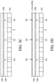
- FIGS. 3 A, 3 B, 3 C, 3 D, 3 E and 3 F are a series of cross-sectional views illustrating a method for forming the semiconductor device according to another embodiment of the present disclosure.
- FIG. 4 is a schematic diagram illustrating the application of the semiconductor device of the embodiments according to the present disclosure to a biometric device.
- FIG. 5 is a schematic diagram illustrating the application of the semiconductor device of the embodiments according to the present disclosure to a biometric device.
- first and second features are formed in direct contact
- additional features may be formed between the first and second features, such that the first and second features may not be in direct contact
- spatially relative terms such as “beneath,” “below,” “lower,” “on,” “above,” “upper” and the like, may be used herein for ease of description to describe one element or feature's relationship to another element(s) or feature(s) as illustrated in the figures.
- the spatially relative terms are intended to encompass different orientations of the device in use or operation in addition to the orientation depicted in the figures.
- the apparatus may be otherwise oriented (rotated 45 degrees or at other orientations) and the spatially relative descriptors used herein may likewise be interpreted accordingly.
- the terms “about” and “substantially” typically mean +/ ⁇ 20% of the stated value, more typically +/ ⁇ 10% of the stated value, more typically +/ ⁇ 5% of the stated value, more typically +/ ⁇ 3% of the stated value, more typically +/ ⁇ 2% of the stated value, more typically +/ ⁇ 1% of the stated value and even more typically +/ ⁇ 0.5% of the stated value.
- the stated value of the present disclosure is an approximate value. That is, when there is no specific description of the terms “about” and “substantially”, the stated value includes the meaning of “about” or “substantially”.
- first,” “second,” “third,” etc. can be used herein to describe various elements, components, regions, layers and/or sections, these elements, components, regions, layers and/or sections should not be limited by these terms. These terms are only used to distinguish one element, component, region, layer or section from another region, layer or section. Thus, a first element, component, region, layer or section discussed below could be termed a second element, component, region, layer or section without departing from the teachings of the present disclosure.
- the light-collimating layer of the semiconductor device includes a plurality of light-shielding layers with holes having different cross-sectional areas. Since the light-shielding layers may be disposed in the light-collimating layer and the transparent material layer may be disposed correspondingly, each of the transparent pillars of the light-collimating layer may have a smaller aspect ratio. This may avoid or reduce the collapse of the transparent pillars and maintain great collimation performance of the light-collimating layer at the same time. The following description will be made with the embodiments shown in FIGS. 1 A- 1 G ′.
- FIGS. 1 A, 1 B, 1 C, 1 D, 1 E, 1 F and 1 G are a series of cross-sectional views illustrating a method for forming the semiconductor device 100 according to an embodiment of the present disclosure.
- FIG. 1 G ′ is a top view illustrating the structure in the step of FIG. 1 G .
- a substrate 101 is provided as shown in FIG. 1 A .
- the substrate 101 may have a top surface 101 T and a bottom surface 101 B opposite the top surface 101 T.
- the substrate 101 may be made of an elementary semiconductor (e.g., silicon or germanium), a compound semiconductor (e.g., silicon carbide (SiC), gallium arsenic (GaAs), indium arsenide (InAs), or indium phosphide (InP)), an alloy semiconductor (e.g., silicon germanium (SiGe), silicon germanium carbide (SiGeC), gallium arsenic phosphide (GaAsP), or gallium indium phosphide (GaInP)), any other applicable semiconductor, or a combination thereof.
- the substrate 101 may be a semiconductor-on-insulator (SOI) substrate.
- SOI semiconductor-on-insulator
- the semiconductor-on-insulator substrate may include a bottom substrate, a buried oxide layer disposed on the bottom substrate, and a semiconductor layer disposed on the buried oxide layer.
- the substrate 101 may be a semiconductor wafer (e.g., a silicon wafer, or any other applicable semiconductor wafer).
- the substrate 101 may include various p-type doped regions and/or n-type doped regions formed by a process such as an ion implantation process and/or a diffusion process.
- the doped regions may be configured to form a transistor, a photodiode, and/or a light-emitting diode, but the present disclosure is not limited thereto.
- the substrate 101 may include various isolation features to separate various device regions in the substrate 101 .
- the isolation features may include a shallow trench isolation (STI) feature, but the present disclosure is not limited thereto.
- the formation of a shallow trench isolation (STI) feature may include etching a trench in the substrate 101 and filling in the trench with insulating materials (e.g., silicon oxide, silicon nitride, or silicon oxynitride).
- the filled trench may have a multi-layer structure, such as a thermal oxide liner layer with silicon nitride filling the trench.
- a chemical mechanical polishing (CMP) process may be performed to polish back excessive insulating materials and planarize the top surface of the isolation features.
- CMP chemical mechanical polishing
- the substrate 101 may include various conductive features (e.g., conductive lines or vias).
- the conductive features may be made of aluminum (Al), copper (Cu), tungsten (W), an alloy thereof, any other applicable conductive material, or a combination thereof.
- the substrate 101 may include a plurality of pixels P.
- the pixels P of the substrate 101 may be arranged in an array, but the present disclosure is not limited thereto.
- each of the pixels P of the substrate 101 may include or correspond to at least one photodiode and/or other applicable elements, which may convert the received light signals into electric current signals.
- a first material 102 is disposed on the top surface 101 T of the substrate 101 as shown in FIG. 1 B .
- the first material 102 may include a metal, such as copper (Cu), silver (Ag), and so on, but the present disclosure is not limited thereto.
- the first material 102 may include photoresist (e.g., black photoresist, or other applicable photoresist which is not transparent), ink (e.g., black ink, or other applicable ink which is not transparent), molding compound (e.g., black molding compound, or other applicable molding compound which is not transparent), solder mask (e.g., black solder mask, or other applicable solder mask which is not transparent), (black-)epoxy polymer, any other applicable material, or a combination thereof.
- the first material 102 may include a light curing material, a thermal curing material, or a combination thereof.
- a patterning process may be performed to pattern the first material 102 and form a first light-shielding layer 104 as shown in FIG. 1 C .
- the light-shielding layer 104 may be in direct contact with the top surface 101 T of the substrate 101 .
- some portions of the first material 102 may be removed in the pattering process to form the first light-shielding layer 104 having a plurality of holes O 1 corresponding to the pixels P.
- the patterning process may include soft baking, mask aligning, exposure, post-exposure baking, developing, rinsing, drying, any other applicable process, or a combination thereof.
- a transparent material 106 is disposed on the top surface 101 T of the substrate 101 as shown in FIG. 1 D .
- the transparent material 106 may include transparent photoresist, polyimide, epoxy resin, any other applicable material, or a combination thereof.
- the transparent material 106 may be used to form the transparent material layer and the transparent pillar (e.g., the transparent material layer 108 and the transparent pillar 110 described later), which will be described in detail in the following description.
- the transparent material 106 may include a light curing material, a thermal curing material, or a combination thereof.
- a spin-on coating process may be performed to coat the transparent material 106 between the first light-shielding layer 104 and the substrate 101 , but the present disclosure is not limited thereto.
- a patterning process may be performed to pattern the transparent material 106 and form a transparent material layer 108 and a plurality of transparent pillars 110 as shown in FIG. 1 E .
- some portions of the transparent material 106 may be removed, and the transparent material 106 remained on the substrate 101 (and remained in the holes O 1 corresponding to the pixels P) may become the transparent material layer 108 and the transparent pillars 110 .
- the patterning process may include soft baking, mask aligning, exposure, post-exposure baking, developing, rinsing, drying, any other applicable process, or a combination thereof.
- the transparent material layer 108 covers the first light-shielding layer 104 and the pixels P and fills the holes O 1 of the first light-shielding layer 104 ; the transparent pillars corresponds to the pixels P.
- the transparent material layer 108 may fully cover (or partially cover) the pixels P in the embodiment shown in FIG. 1 E .
- the transparent material layer 108 (and the first light-shielding layer 104 ) covering the pixels may reduce or avoid the pixels from being damage and/or contaminated during the manufacturing process.
- the transparent pillars 110 may be arranged in an array, but the present disclosure is not limited thereto.
- a second material 112 is disposed in the top surface of the transparent material layer 108 as shown in FIG. 1 F .
- the second material 112 may fill the openings between the transparent pillars 110 and cover the transparent pillars 110 .
- the first material 102 is different from the second material 112 .
- the first material 102 may include a metal
- the second material 112 may include photoresist (e.g., black photoresist, or other applicable photoresist which is not transparent), ink (e.g., black ink, or other applicable ink which is not transparent), molding compound (e.g., black molding compound, or other applicable molding compound which is not transparent), solder mask (e.g., black solder mask, or other applicable solder mask which is not transparent), (black-)epoxy polymer, any other applicable material, or a combination thereof.
- photoresist e.g., black photoresist, or other applicable photoresist which is not transparent
- ink e.g., black ink, or other applicable ink which is not transparent
- molding compound e.g., black molding compound, or other applicable molding compound which is not transparent
- solder mask e.g., black solder mask, or other applicable solder mask which is not
- the second material 112 may include a light curing material, a thermal curing material, or a combination thereof, but the present disclosure is not limited thereto.
- the first material 102 may be the same as the second material 112 . That is, the first material 102 may include photoresist, ink, molding compound, solder mask, (black-)epoxy polymer, any other applicable material, or a combination thereof.
- a curing process may be performed to cure the second material 112 as shown in FIG. 1 G .
- the curing process may be a light curing process, a thermal curing process, or a combination thereof.
- a planarization process may be performed to remove some portions of the second material 112 , such that the top surfaces of the transparent pillars 110 may be exposed and the second light-shielding layer 114 may be formed.
- some portions of the transparent pillars 110 (e.g., some portions of the top of the transparent pillars 110 ) may also be removed during the planarization process.
- the planarization process may include a chemical mechanical polishing (CMP) process, a grinding process, an etching back process, any other applicable process, or a combination thereof.
- CMP chemical mechanical polishing
- the top surface of the second light-shielding layer 114 and the top surfaces of the transparent pillars 110 may be aligned with each other after the planarization process. That is, the top surface of the second light-shielding layer 114 and the top surfaces of the transparent pillars 110 may be coplanar after the planarization process.
- the second light-shielding layer 114 may surround the transparent pillars 110 as shown in FIG. 1 G and FIG. 1 G ′. That is, the transparent pillars 110 may be disposed in the second light-shielding layer 114 in the embodiment as shown in FIG. 1 G and FIG. 1 G ′.
- the top surface of each of the transparent pillars 110 may be round as shown in FIG. 1 G ′, but the present disclosure is not limited thereto. In other embodiments, the top surface of each of the transparent pillars 110 may be oval, oblong, rectangular, hexagonal, irregular-shaped, any other applicable shape, or a combination thereof.
- the transparent pillars 110 correspond to the pixels, the transparent pillars 110 also correspond to the holes O 1 of the first light-shielding layer 104 .
- the width W 2 of one of the transparent pillars 110 is larger than the width W 1 of the corresponding one of the holes O 1 .
- the width W 2 of the transparent pillar 110 may be between 6 and 20 ⁇ m, and the width W 1 of the hole O 1 may be between 1 and 10 ⁇ m.
- the width W 2 of the transparent pillar 110 is defined as the largest width in the cross-sectional area of the transparent pillar 110
- the width W 1 of the hole O 1 is defined as the largest width in the cross-sectional area of the hole O 1 .
- the cross-sectional area of the transparent pillar 110 is a circle, and the width W 2 of the transparent pillar 110 is therefore the diameter of the circle; the cross-sectional area of hole O 1 is a circle, and the width W 1 of the hole O 1 is therefore the diameter of the circle.
- the thicknesses of the light-shielding layers may be different from each other.
- the thickness T 1 of the first light-shielding layer 104 is smaller than the thickness T 2 of the second light-shielding layer 114 in the embodiment as shown in FIG. 1 G .
- the thickness T 1 of the first light-shielding layer 104 may be between 4 and 20 ⁇ m
- the thickness T 2 of the second light-shielding layer 114 may be between 10 and 90 ⁇ m. But the present disclosure is not limited thereto.
- the transparent pillars 110 , the first light-shielding layer 104 , the second light-shielding layer 114 and the transparent material layer 108 may serve as the light-collimating layer 116 of the semiconductor device 100 as shown in FIG. 1 G .
- the spaces occupied by the transparent pillars 110 may be regarded as a plurality of holes O 2 of the second light-shielding layer 114 .
- the holes O 2 correspond to the pixels P, and the cross-sectional area of each hole O 1 of the first light-shielding layer 104 may be smaller than the cross-sectional area of each hole O 2 of the second light-shielding layer 114 .
- the size of the hole O 2 of the second light-shielding layer 114 and the size of the hole O 1 of the first light-shielding layer 104 may be adjusted in accordance with the paths of the lights to avoid the lights in the semiconductor device 100 from crosstalk.
- the transparent material layer 108 may be correspondingly disposed, such that each of the transparent pillars 110 of the light-collimating layer 116 may have a smaller aspect ratio (e.g., the ratio of the height H 1 and the width W 2 of one of the transparent pillars 110 (i.e., H 1 /W 2 ) may be between 0.5 and 15). This may avoid or reduce the collapse of the transparent pillars 110 and maintain great collimation performance of the light-collimating layer 116 at the same time.
- FIG. 2 is a schematic diagram illustrating the application of the semiconductor device 100 of the embodiments according to the present disclosure to a biometric device 10 .
- the biometric device 10 may be a fingerprint identification device, for example.
- the biometric device 10 may include the semiconductor device 100 , a color filter layer 118 and a light source layer 120 as shown in FIG. 2 .
- the semiconductor device 100 may be formed according to the steps shown in FIGS. 1 A- 1 G .
- the color filter layer 118 may be disposed on the semiconductor device 100 .
- the color filter layer 118 may be made of a polymer material or another suitable material.
- the color filter layer 118 is configured to limit the passage of light, such that the light with a specific wavelength may pass through the color filter layer 118 , and the light with other wavelengths may be isolated.
- the light source layer 120 may be disposed on the color filter layer 118 .
- light source layer 120 may include a plurality of light sources (e.g., light emitting diode, LED) 122 .
- the light sources 122 may be arranged in an array, for example.
- the light source layer 120 may further include a barrier layer, other suitable optical components, or a combination thereof (not shown).
- a cover plate (e.g., glass cover plate) 124 may be disposed on the top of the light source layer 120 to form a biometric device (e.g., fingerprint identification device).
- the light source layer 120 may include other elements which is not shown in FIG. 2 . The present disclosure is not limited thereto.
- the lights emitting from the light sources 122 may be blocked by the biometric characteristics (e.g., fingerprints FP) from outside, and then different reflected lights L are generated and enter the color filter layer 118 .
- the color filter layer 118 may limit the reflected lights L, such that the light L 1 with the specific wavelength corresponding to the pixels P (e.g., including or corresponding to at least one photoelectric diode (PD) and/or other suitable components) may pass through the color filter layer 118 , and the light with other wavelengths may be isolated.
- the light L 1 passing through the color filter layer 118 then enter the transparent pillars 110 inside the second light-shielding layer 114 .
- the second light-shielding layer 114 may be black (e.g., formed of black photoresist, black ink, black molding compound or black solder mask) and the size of the hole O 2 of the second light-shielding layer 114 (or the width W 2 of the transparent pillar 110 ) may be adjusted in accordance with the path of the light, it may avoid the lights L 1 from crosstalk and enhance the collimation performance of the light-collimating layer 116 .
- the lights L 1 passing through the transparent pillar 110 enter the transparent material layer 118 , and then pass though the holes O 1 of the first light-shielding layer 104 to enter the pixels P.
- the size of the hole O 1 of the first light-shielding layer 104 may be adjusted in accordance with the path of the light, it may avoid the lights L 1 from crosstalk and enhance the collimation performance of the light-collimating layer 116 .
- using the metal (e.g., copper, silver) as the first material 102 for forming the first light-shielding layer 104 may effectively simplify the manufacturing process. Moreover, it may be known from the path of the lights L (of lights L 1 ) that since the size of each hole (e.g., hole O 1 and hole O 2 ) of the plurality of light-shielding layers (e.g., the first light-shielding layer 104 and the second light-shielding layer 114 ) may be adjusted in accordance with the path of the lights, it may effectively limit the positions of the lights to avoid the lights from crosstalk.
- the metal e.g., copper, silver
- the transparent material layer 108 may be correspondingly disposed, such that each of the transparent pillars 110 of the light-collimating layer 116 may have a smaller aspect ratio. This may avoid or reduce the collapse of the transparent pillars 110 and maintain great collimation performance of the light-collimating layer 116 at the same time (i.e., the resolution of the pixels P may be more improved).
- FIGS. 3 A, 3 B, 3 C, 3 D, 3 E and 3 F are a series of cross-sectional views illustrating a method for forming the semiconductor device 100 ′ according to another embodiment of the present disclosure. Some differences between the semiconductor device 100 ′ and the semiconductor device 100 include the position of the first light-shielding layer 204 and the structure of the second light-shielding layer 214 - 1 . It will be described in detail in the following description.
- a substrate 101 is provided as shown in FIG. 3 A .
- the substrate 101 may have a top surface 101 T and a bottom surface 101 B opposite the top surface 101 T.
- the substrate 101 may include a plurality of pixels P.
- the pixels P of the substrate 101 may be arranged in an array, but the present disclosure is not limited thereto.
- each of the pixels P of the substrate 101 may include or correspond to at least one photodiode and/or other applicable elements, which may convert the received light signals into electric current signals.
- a transparent material 106 is disposed on the top surface 101 T of the substrate 101 , such that the transparent material 106 may fully cover (or partially cover) the pixels P.
- the transparent material 106 may include transparent photoresist, polyimide, epoxy resin, any other applicable material, or a combination thereof.
- the transparent material 106 may be used to form the transparent material layer and the transparent pillar (e.g., the transparent material layer 108 and the transparent pillar 210 described later), which will be described in detail in the following description.
- the transparent material 106 may include a light curing material, a thermal curing material, or a combination thereof.
- a spin-on coating process may be performed to coat the transparent material 106 on the top surface 101 T of the substrate 101 , but the present disclosure is not limited thereto.
- a light-shielding material 202 is disposed on the transparent material 106 as shown in FIG. 3 B .
- the light-shielding material 202 may include photoresist (e.g., black photoresist, or other applicable photoresist which is not transparent), ink (e.g., black ink, or other applicable ink which is not transparent), molding compound (e.g., black molding compound, or other applicable molding compound which is not transparent), solder mask (e.g., black solder mask, or other applicable solder mask which is not transparent), (black-)epoxy polymer, any other applicable material, or a combination thereof.
- photoresist e.g., black photoresist, or other applicable photoresist which is not transparent
- ink e.g., black ink, or other applicable ink which is not transparent
- molding compound e.g., black molding compound, or other applicable molding compound which is not transparent
- solder mask e.g., black solder mask, or other
- the light-shielding material 202 may include a light curing material, a thermal curing material, or a combination thereof, but the present disclosure is not limited thereto. In other embodiments, the light-shielding material 202 may also include a metal, such as copper, silver, and so on.
- a patterning process may be performed to pattern the light-shielding material 202 and form a first light-shielding layer 204 as shown in FIG. 3 B .
- some portions of the light-shielding material 202 may be removed in the pattering process to form the first light-shielding layer 204 having a plurality of holes O 1 corresponding to the pixels P.
- the patterning process may include soft baking, mask aligning, exposure, post-exposure baking, developing, rinsing, drying, any other applicable process, or a combination thereof.
- the transparent material 106 is disposed on the first light-shielding layer 204 as shown in FIG. 3 C , such that the transparent material 106 may fully cover (or partially cover) the first light-shielding layer 204 fill the holes O 1 of the first light-shielding layer 204 .
- the light-shielding material 202 is disposed on the transparent material 106 again a patterning process may be performed to pattern the light-shielding material 202 and form a second light-shielding layer 214 - 1 as shown in FIG. 3 D .
- some portions of the light-shielding material 202 may be removed in the pattering process to form the second light-shielding layer 214 - 1 having a plurality of holes O 2 corresponding to the pixels P.
- the patterning process may include soft baking, mask aligning, exposure, post-exposure baking, developing, rinsing, drying, any other applicable process, or a combination thereof.
- the transparent material 106 is disposed on the second light-shielding layer 214 - 1 as shown in FIG. 3 E , such that the transparent material 106 may fully cover (or partially cover) the second light-shielding layer 214 - 1 fill the holes O 2 of the second light-shielding layer 214 - 1 .
- the light-shielding material 202 is disposed on the transparent material 106 again a patterning process may be performed to pattern the light-shielding material 202 and form a third light-shielding layer 214 - 2 as shown in FIG. 3 F .
- some portions of the light-shielding material 202 may be removed in the pattering process to form the third light-shielding layer 214 - 2 having a plurality of holes O 3 corresponding to the pixels P.
- the patterning process may include soft baking, mask aligning, exposure, post-exposure baking, developing, rinsing, drying, any other applicable process, or a combination thereof.
- the transparent material 106 may optionally fill the holes O 3 of the third light-shielding layer 214 - 2 to planarize the top surface of the third light-shielding layer 214 - 2 , but the present disclosure is not limited thereto.
- a transparent material layer 208 formed of the transparent material 106 may include a raised portion 208 - 1 and separating portions 208 - 2 .
- the raised portion 208 - 1 may be disposed between the substrate 101 and the first light-shielding layer 204
- the separating portions may be disposed between the first light-shielding layer 204 and the second light-shielding layer 214 - 1 and between the second light-shielding layer 214 - 1 and the third light-shielding layer 214 - 2 .
- the transparent material filled in the holes O 1 of the first light-shielding layer 204 , the transparent material filled in the holes O 2 of the second light-shielding layer 214 - 1 , the transparent material filled in the holes O 3 of the third light-shielding layer 214 - 2 optionally may be regarded as transparent pillars 210 of the semiconductor device 100 ′ as shown in FIG. 3 F . That is, the transparent pillars 210 may be disposed in the first light-shielding layer 204 , the second light-shielding layer 214 - 1 , and the third light-shielding layer 214 - 2 .
- each of the transparent pillars 210 may be round, but the present disclosure is not limited thereto. In other embodiments, the top surface of each of the transparent pillars 210 may be oval, oblong, rectangular, hexagonal, irregular-shaped, any other applicable shape, or a combination thereof.
- the transparent pillars 210 , the first light-shielding layer 204 , the second light-shielding layer 214 - 1 , the third light-shielding layer 214 - 2 and the transparent material layer 208 may serve as the light-collimating layer 216 of the semiconductor device 100 ′ as shown in FIG. 3 F .
- the cross-sectional area of each hole O 2 of the second light-shielding layer 214 - 1 may be different from the cross-sectional area of each hole O 3 of the third light-shielding layer O 3 .
- the cross-sectional area of each hole O 2 of the second light-shielding layer 214 - 1 may be different from the cross-sectional area of each hole O 3 of the third light-shielding layer O 3 .
- the cross-sectional area of each hole O 2 of the second light-shielding layer 214 - 1 is smaller than the cross-sectional area of each hole O 3 of the third light-shielding layer O 3 ;
- the cross-sectional area of each hole O 1 of the first light-shielding layer 204 is larger than the cross-sectional area of each hole O 2 of the second light-shielding layer 214 - 1 , but smaller than the cross-sectional area of each hole O 3 of the third light-shielding layer 214 - 2 .
- the cross-sectional area of each hole O 1 of the first light-shielding layer 204 may be equal to the cross-sectional area of each hole O 3 of the third light-shielding layer O 3 .
- the size of the hole O 1 of the first light-shielding layer 204 , the size of the hole O 2 of the second light-shielding layer 214 - 1 and the size of the hole O 3 of the third light-shielding layer 214 - 2 may be adjusted in accordance with the paths of the lights to avoid the lights in the semiconductor device 100 ′ from crosstalk.
- the transparent material layer 208 may be correspondingly disposed, such that each of the transparent pillars 210 of the light-collimating layer 216 may have a smaller aspect ratio. This may avoid or reduce the collapse of the transparent pillars 210 and maintain great collimation performance of the light-collimating layer 216 at the same time.
- the thickness T 2 ′ of the second light-shielding layer 214 - 1 may be different from the thickness T 3 ′ of the third light-shielding layer 214 - 2 , but the present disclosure is not limited thereto. In other embodiments, the thickness T 1 ′ of the first light-shielding layer 204 , the thickness T 2 ′ of the second light-shielding layer 214 - 1 , and the thickness T 3 ′ of the third light-shielding layer 214 - 2 may be the same.
- the thickness T 1 ′ of the first light-shielding layer 204 , the thickness T 2 ′ of the second light-shielding layer 214 - 1 , and the thickness T 3 ′ of the third light-shielding layer 214 - 2 may be changed in accordance with the actual demand.
- the distance between the first light-shielding layer 204 and the second light-shielding layer 214 - 1 and the distance between the second light-shielding layer 214 - 1 and the third light-shielding layer 214 - 2 may be different from each other, which may be adjusted in accordance with the paths of the lights.
- the semiconductor device 100 ′ may not include the third light-shielding layer 214 - 2 in some embodiments. Furthermore, the process steps as shown in FIGS. 3 C- 3 D (or FIGS. 3 E- 3 F ) may be repeated to form more light-shielding layers. The number of the light-shielding layers is not limited in the present disclosure, and may be changed in accordance with the actual demand.
- FIG. 4 is a schematic diagram illustrating the application of the semiconductor device 100 ′ of the embodiments according to the present disclosure to a biometric device 10 ′.
- the biometric device 10 ′ may be a fingerprint identification device, for example.
- the biometric device 10 ′ may include the semiconductor device 100 ′, a color filter layer 118 and a light source layer 120 as shown in FIG. 4 .
- the semiconductor device 100 ′ may be formed according to the steps shown in FIGS. 3 A- 3 F .
- the color filter layer 118 may be disposed on the semiconductor device 100 ′.
- the color filter layer 118 may be made of a polymer material or another suitable material.
- the color filter layer 118 is configured to limit the passage of light, such that the light with a specific wavelength may pass through the color filter layer 118 , and the light with other wavelengths may be isolated.
- the light source layer 120 may be disposed on the color filter layer 118 .
- light source layer 120 may include a plurality of light sources (e.g., light emitting diode, LED) 122 .
- the light sources 122 may be arranged in an array, for example.
- the light source layer 120 may further include a barrier layer, other suitable optical components, or a combination thereof (not shown).
- a cover plate (e.g., glass cover plate) 124 may be disposed on the top of the light source layer 120 to form a biometric device (e.g., fingerprint identification device).
- the light source layer 120 may include other elements which is not shown in FIG. 4 . The present disclosure is not limited thereto.
- the lights emitting from the light sources 122 may be blocked by the biometric characteristics (e.g., fingerprints FP) from outside, and then different reflected lights L are generated and enter the color filter layer 118 .
- the color filter layer 118 may limit the reflected lights L, such that the light L 1 with the specific wavelength corresponding to the pixels P (e.g., including or corresponding to at least one photoelectric diode (PD) and/or other suitable components) may pass through the color filter layer 118 , and the light with other wavelengths may be isolated.
- the biometric characteristics e.g., fingerprints FP
- the color filter layer 118 may limit the reflected lights L, such that the light L 1 with the specific wavelength corresponding to the pixels P (e.g., including or corresponding to at least one photoelectric diode (PD) and/or other suitable components) may pass through the color filter layer 118 , and the light with other wavelengths may be isolated.
- PD photoelectric diode
- the light L 1 passing through the color filter layer 118 then sequentially enter the transparent pillars 210 inside the first light-shielding layer 204 , the second light-shielding layer 214 - 1 and the third light-shielding layer 214 - 2 .
- the first light-shielding layer 204 , the second light-shielding layer 214 - 1 and the third light-shielding layer 214 - 2 may be black (e.g., formed of black photoresist, black ink, black molding compound or black solder mask) and the size of the hole O 1 of the first light-shielding layer 204 , the size of the hole O 2 of the second light-shielding layer 214 - 1 and the size of the hole O 3 of the third light-shielding layer 214 - 2 (or the width of the transparent pillar 210 ) may be adjusted in accordance with the path of the light, it may avoid the lights L 1 from crosstalk and enhance the collimation performance of the light-collimating layer 216 .
- black e.g., formed of black photoresist, black ink, black molding compound or black solder mask
- each hole e.g., hole O 1 , hole O 2 and hole O 3
- the transparent material layer 208 may be correspondingly disposed, such that each of the transparent pillars 210 of the light-collimating layer 216 may have a smaller aspect ratio. This may avoid or reduce the collapse of the transparent pillars 210 and maintain great collimation performance of the light-collimating layer 216 at the same time (i.e., the resolution of the pixels P may be more improved).
- FIG. 5 is a schematic diagram illustrating the application of the semiconductor device 100 ′′ of the embodiments according to the present disclosure to a biometric device 10 ′′.
- the biometric device 10 ′′ may be a fingerprint identification device, for example.
- the biometric device 10 ′′ may include the semiconductor device 100 ′′, a color filter layer 118 and a light source layer 220 as shown in FIG. 5 .
- Some differences between the semiconductor device 100 ′′ as shown in FIG. 5 and the semiconductor device 100 ′ as shown in FIG. 4 (or FIG. 3 F ) include the thickness of the raised portion 308 - 1 of the transparent material layer 308 , the size of the hole O 1 of the first light-shielding layer 304 , the size of the hole O 2 of the second light-shielding layer 314 - 1 and the size of the hole O 3 of the third light-shielding layer 314 - 2 .
- Other same or similar features will not be mentioned repeatedly.
- the thickness T 5 of the raised portion 308 - 1 of the transparent material layer 308 as shown in FIG. 5 is larger than the thickness T 4 of the raised portion 208 - 1 of the transparent material layer 208 as shown in FIG. 4 (or FIG. 3 F ). Therefore, the size of the hole O 1 of the first light-shielding layer 304 , the size of the hole O 2 of the second light-shielding layer 314 - 1 and the size of the hole O 3 of the third light-shielding layer 314 - 2 , which may be adjusted in accordance with the paths of the lights as shown in FIG.
- the size of the hole O 1 of the first light-shielding layer 204 may be different from the size of the hole O 2 of the second light-shielding layer 214 - 1 and the size of the hole O 3 of the third light-shielding layer 214 - 2 as shown in FIG. 4 (or FIG. 3 F ).
- each hole O 3 of the third light-shielding layer 314 - 2 may be larger than the cross-sectional area of each hole O 2 of the second light-shielding layer 314 - 1
- the cross-sectional area of each hole O 2 of the second light-shielding layer 314 - 1 may be larger than the cross-sectional area of each hole O 1 of the first light-shielding layer 304 .
- the separating portions 308 - 2 of the transparent material layer 308 as shown in FIG. 5 may be different from the separating portions 208 - 2 of the transparent material layer 208 as shown in FIG. 4 (or FIG. 3 F ).
- the thickness of the light source layer 220 may be reduced because the raised portion 308 - 1 of the transparent material layer 308 becomes thicker.
- the light-collimating layer of the semiconductor device in the embodiments according to the present disclosure includes a plurality of light-shielding layers with holes having different cross-sectional areas. Since the light-shielding layers may be disposed in the light-collimating layer and the transparent material layer may be disposed correspondingly, each of the transparent pillars of the light-collimating layer may have a smaller aspect ratio. This may avoid or reduce the collapse of the transparent pillars and maintain great collimation performance of the light-collimating layer at the same time.
- each claim may be an individual embodiment of the present disclosure, and the scope of the present disclosure includes the combinations of every claim and every embodiment of the present disclosure.
Landscapes
- Physics & Mathematics (AREA)
- General Physics & Mathematics (AREA)
- Optics & Photonics (AREA)
- Solid State Image Pick-Up Elements (AREA)
Abstract
A semiconductor device is provided. The semiconductor device includes a substrate and a light-collimating layer. The substrate has a plurality of pixels. The light-collimating layer is disposed on the substrate, and the light-collimating layer includes a transparent material layer, a first light-shielding layer, a second light-shielding layer and a plurality of transparent pillars. The transparent material layer covers the pixels. The first light-shielding layer is disposed on the substrate and the first light-shielding layer has a plurality of holes corresponding to the pixels. The second light-shielding layer is disposed on the first light-shielding layer. The transparent pillars are disposed in the second light-shielding layer.
Description
This application is a Divisional of U.S. patent application Ser. No. 16/361,853, filed Mar. 22, 2019 and entitled “SEMICONDUCTOR DEVICE INCLUDING LIGHT-COLLIMATING LAYER”.
Embodiments of the present disclosure relate to a semiconductor device, and in particular they relate to a semiconductor device that includes a light-collimating layer.
Semiconductor devices may be used in a variety of applications. For example, a semiconductor device may be used as at least one portion of a biometric device, such as a fingerprint identification device, a facial-recognition device, an iris scanner, etc. Such a biometric device may be composed of a large number of optical components, which may include a light collimator.
The light collimator may be used to collimate the light for reducing the energy lost due to light divergence. Therefore, a light collimator may be applied in a biometric device (e.g., a fingerprint identification device) to enhance the efficiency of identification.
However, existing light collimators have not been satisfactory in every respect.
Some embodiments of the present disclosure relate to a semiconductor device. The semiconductor device includes a substrate and a light-collimating layer. The substrate has a plurality of pixels. The light-collimating layer is disposed on the substrate, and the light-collimating layer includes a transparent material layer, a first light-shielding layer, a second light-shielding layer and a plurality of transparent pillars. The transparent material layer covers the pixels. The first light-shielding layer is disposed on the substrate and the first light-shielding layer has a plurality of holes corresponding to the pixels. The second light-shielding layer is disposed on the first light-shielding layer. The transparent pillars are disposed in the second light-shielding layer.
Some embodiments of the present disclosure relate to a semiconductor device. The semiconductor device includes a substrate and a light-collimating layer. The substrate has a plurality of pixels. The light-collimating layer is disposed on the substrate, and the light-collimating layer includes a plurality of light-shielding layers and a transparent material layer. The light-shielding layers are disposed on the substrate, and each of the light-shielding layers has a plurality of holes corresponding to the pixels. The transparent material layer is disposed between the light-shielding layers and filling the holes.
Aspects of the embodiments of the present disclosure are best understood from the following detailed description when read with the accompanying figures. It should be noted that, in accordance with the standard practice in the industry, various features are not drawn to scale. In fact, the dimensions of the various features may be arbitrarily increased or reduced for clarity of discussion.
The following disclosure provides many different embodiments, or examples, for implementing different features of the subject matter provided. Specific examples of components and arrangements are described below to simplify the present disclosure. These are, of course, merely examples and are not intended to be limiting. For example, the formation of a first feature over or on a second feature in the description that follows may include embodiments in which the first and second features are formed in direct contact, and may also include embodiments in which additional features may be formed between the first and second features, such that the first and second features may not be in direct contact.
It should be understood that additional steps may be implemented before, during, or after the illustrated methods, and some steps might be replaced or omitted in other embodiments of the illustrated methods.
Furthermore, spatially relative terms, such as “beneath,” “below,” “lower,” “on,” “above,” “upper” and the like, may be used herein for ease of description to describe one element or feature's relationship to another element(s) or feature(s) as illustrated in the figures. The spatially relative terms are intended to encompass different orientations of the device in use or operation in addition to the orientation depicted in the figures. The apparatus may be otherwise oriented (rotated 45 degrees or at other orientations) and the spatially relative descriptors used herein may likewise be interpreted accordingly.
In the present disclosure, the terms “about” and “substantially” typically mean +/−20% of the stated value, more typically +/−10% of the stated value, more typically +/−5% of the stated value, more typically +/−3% of the stated value, more typically +/−2% of the stated value, more typically +/−1% of the stated value and even more typically +/−0.5% of the stated value. The stated value of the present disclosure is an approximate value. That is, when there is no specific description of the terms “about” and “substantially”, the stated value includes the meaning of “about” or “substantially”.
It should be understood that, although the terms “first,” “second,” “third,” etc. can be used herein to describe various elements, components, regions, layers and/or sections, these elements, components, regions, layers and/or sections should not be limited by these terms. These terms are only used to distinguish one element, component, region, layer or section from another region, layer or section. Thus, a first element, component, region, layer or section discussed below could be termed a second element, component, region, layer or section without departing from the teachings of the present disclosure.
Unless otherwise defined, all terms (including technical and scientific terms) used herein have the same meaning as commonly understood by one of ordinary skill in the art to which this disclosure belongs. It should be understood that terms such as those defined in commonly used dictionaries should be interpreted as having a meaning that is consistent with their meaning in the context of the relevant art and will not be interpreted in an idealized or overly formal sense unless expressly so defined in the embodiments of the present disclosure.
In some embodiments of the present disclosure, the light-collimating layer of the semiconductor device includes a plurality of light-shielding layers with holes having different cross-sectional areas. Since the light-shielding layers may be disposed in the light-collimating layer and the transparent material layer may be disposed correspondingly, each of the transparent pillars of the light-collimating layer may have a smaller aspect ratio. This may avoid or reduce the collapse of the transparent pillars and maintain great collimation performance of the light-collimating layer at the same time. The following description will be made with the embodiments shown in FIGS. 1A-1G ′.
First, according to some embodiments, a substrate 101 is provided as shown in FIG. 1A . The substrate 101 may have a top surface 101T and a bottom surface 101B opposite the top surface 101T.
In some embodiments, the substrate 101 may be made of an elementary semiconductor (e.g., silicon or germanium), a compound semiconductor (e.g., silicon carbide (SiC), gallium arsenic (GaAs), indium arsenide (InAs), or indium phosphide (InP)), an alloy semiconductor (e.g., silicon germanium (SiGe), silicon germanium carbide (SiGeC), gallium arsenic phosphide (GaAsP), or gallium indium phosphide (GaInP)), any other applicable semiconductor, or a combination thereof. In some embodiments, the substrate 101 may be a semiconductor-on-insulator (SOI) substrate. The semiconductor-on-insulator substrate may include a bottom substrate, a buried oxide layer disposed on the bottom substrate, and a semiconductor layer disposed on the buried oxide layer. In some embodiments, the substrate 101 may be a semiconductor wafer (e.g., a silicon wafer, or any other applicable semiconductor wafer).
In some embodiments, the substrate 101 may include various p-type doped regions and/or n-type doped regions formed by a process such as an ion implantation process and/or a diffusion process. For example, the doped regions may be configured to form a transistor, a photodiode, and/or a light-emitting diode, but the present disclosure is not limited thereto.
In some embodiments, the substrate 101 may include various isolation features to separate various device regions in the substrate 101. For example, the isolation features may include a shallow trench isolation (STI) feature, but the present disclosure is not limited thereto. The formation of a shallow trench isolation (STI) feature may include etching a trench in the substrate 101 and filling in the trench with insulating materials (e.g., silicon oxide, silicon nitride, or silicon oxynitride). The filled trench may have a multi-layer structure, such as a thermal oxide liner layer with silicon nitride filling the trench. A chemical mechanical polishing (CMP) process may be performed to polish back excessive insulating materials and planarize the top surface of the isolation features.
In some embodiments, the substrate 101 may include various conductive features (e.g., conductive lines or vias). For example, the conductive features may be made of aluminum (Al), copper (Cu), tungsten (W), an alloy thereof, any other applicable conductive material, or a combination thereof.
In the embodiment as shown in FIG. 1A , the substrate 101 may include a plurality of pixels P. In some embodiments, the pixels P of the substrate 101 may be arranged in an array, but the present disclosure is not limited thereto.
In some embodiments, each of the pixels P of the substrate 101 may include or correspond to at least one photodiode and/or other applicable elements, which may convert the received light signals into electric current signals.
Next, in some embodiments, a first material 102 is disposed on the top surface 101T of the substrate 101 as shown in FIG. 1B . In this embodiment, the first material 102 may include a metal, such as copper (Cu), silver (Ag), and so on, but the present disclosure is not limited thereto. In other embodiments, the first material 102 may include photoresist (e.g., black photoresist, or other applicable photoresist which is not transparent), ink (e.g., black ink, or other applicable ink which is not transparent), molding compound (e.g., black molding compound, or other applicable molding compound which is not transparent), solder mask (e.g., black solder mask, or other applicable solder mask which is not transparent), (black-)epoxy polymer, any other applicable material, or a combination thereof. In some embodiments, the first material 102 may include a light curing material, a thermal curing material, or a combination thereof.
Next, a patterning process may be performed to pattern the first material 102 and form a first light-shielding layer 104 as shown in FIG. 1C . The light-shielding layer 104 may be in direct contact with the top surface 101T of the substrate 101. In more detail, some portions of the first material 102 may be removed in the pattering process to form the first light-shielding layer 104 having a plurality of holes O1 corresponding to the pixels P. In some embodiments, the patterning process may include soft baking, mask aligning, exposure, post-exposure baking, developing, rinsing, drying, any other applicable process, or a combination thereof.
Next, a transparent material 106 is disposed on the top surface 101T of the substrate 101 as shown in FIG. 1D . For example, the transparent material 106 may include transparent photoresist, polyimide, epoxy resin, any other applicable material, or a combination thereof. In the subsequent processes, the transparent material 106 may be used to form the transparent material layer and the transparent pillar (e.g., the transparent material layer 108 and the transparent pillar 110 described later), which will be described in detail in the following description.
In some embodiments, the transparent material 106 may include a light curing material, a thermal curing material, or a combination thereof. For example, a spin-on coating process may be performed to coat the transparent material 106 between the first light-shielding layer 104 and the substrate 101, but the present disclosure is not limited thereto.
Next, a patterning process may be performed to pattern the transparent material 106 and form a transparent material layer 108 and a plurality of transparent pillars 110 as shown in FIG. 1E . In more detail, some portions of the transparent material 106 may be removed, and the transparent material 106 remained on the substrate 101 (and remained in the holes O1 corresponding to the pixels P) may become the transparent material layer 108 and the transparent pillars 110. Similarly, in some embodiments, the patterning process may include soft baking, mask aligning, exposure, post-exposure baking, developing, rinsing, drying, any other applicable process, or a combination thereof.
As shown in FIG. 1E , in this embodiment, the transparent material layer 108 covers the first light-shielding layer 104 and the pixels P and fills the holes O1 of the first light-shielding layer 104; the transparent pillars corresponds to the pixels P. In other words, the transparent material layer 108 may fully cover (or partially cover) the pixels P in the embodiment shown in FIG. 1E . In some embodiments, the transparent material layer 108 (and the first light-shielding layer 104) covering the pixels may reduce or avoid the pixels from being damage and/or contaminated during the manufacturing process. In some embodiments, the transparent pillars 110 may be arranged in an array, but the present disclosure is not limited thereto.
Next, in some embodiments, a second material 112 is disposed in the top surface of the transparent material layer 108 as shown in FIG. 1F . In some embodiments, the second material 112 may fill the openings between the transparent pillars 110 and cover the transparent pillars 110.
In this embodiment, the first material 102 is different from the second material 112. For example, the first material 102 may include a metal, while the second material 112 may include photoresist (e.g., black photoresist, or other applicable photoresist which is not transparent), ink (e.g., black ink, or other applicable ink which is not transparent), molding compound (e.g., black molding compound, or other applicable molding compound which is not transparent), solder mask (e.g., black solder mask, or other applicable solder mask which is not transparent), (black-)epoxy polymer, any other applicable material, or a combination thereof. In some embodiments, the second material 112 may include a light curing material, a thermal curing material, or a combination thereof, but the present disclosure is not limited thereto. In other embodiments, the first material 102 may be the same as the second material 112. That is, the first material 102 may include photoresist, ink, molding compound, solder mask, (black-)epoxy polymer, any other applicable material, or a combination thereof.
Next, a curing process may be performed to cure the second material 112 as shown in FIG. 1G . For example, the curing process may be a light curing process, a thermal curing process, or a combination thereof. Then, a planarization process may be performed to remove some portions of the second material 112, such that the top surfaces of the transparent pillars 110 may be exposed and the second light-shielding layer 114 may be formed. In some embodiments, some portions of the transparent pillars 110 (e.g., some portions of the top of the transparent pillars 110) may also be removed during the planarization process. For example, the planarization process may include a chemical mechanical polishing (CMP) process, a grinding process, an etching back process, any other applicable process, or a combination thereof.
In some embodiments, the top surface of the second light-shielding layer 114 and the top surfaces of the transparent pillars 110 may be aligned with each other after the planarization process. That is, the top surface of the second light-shielding layer 114 and the top surfaces of the transparent pillars 110 may be coplanar after the planarization process.
In some embodiments, the second light-shielding layer 114 may surround the transparent pillars 110 as shown in FIG. 1G and FIG. 1G ′. That is, the transparent pillars 110 may be disposed in the second light-shielding layer 114 in the embodiment as shown in FIG. 1G and FIG. 1G ′. In some embodiments, the top surface of each of the transparent pillars 110 may be round as shown in FIG. 1G ′, but the present disclosure is not limited thereto. In other embodiments, the top surface of each of the transparent pillars 110 may be oval, oblong, rectangular, hexagonal, irregular-shaped, any other applicable shape, or a combination thereof.
Moreover, since the transparent pillars 110 correspond to the pixels, the transparent pillars 110 also correspond to the holes O1 of the first light-shielding layer 104. In some embodiments, the width W2 of one of the transparent pillars 110 is larger than the width W1 of the corresponding one of the holes O1. For example, the width W2 of the transparent pillar 110 may be between 6 and 20 μm, and the width W1 of the hole O1 may be between 1 and 10 μm. Here, the width W2 of the transparent pillar 110 is defined as the largest width in the cross-sectional area of the transparent pillar 110, and the width W1 of the hole O1 is defined as the largest width in the cross-sectional area of the hole O1. For example, the cross-sectional area of the transparent pillar 110 is a circle, and the width W2 of the transparent pillar 110 is therefore the diameter of the circle; the cross-sectional area of hole O1 is a circle, and the width W1 of the hole O1 is therefore the diameter of the circle.
In some embodiments, the thicknesses of the light-shielding layers may be different from each other. For example, the thickness T1 of the first light-shielding layer 104 is smaller than the thickness T2 of the second light-shielding layer 114 in the embodiment as shown in FIG. 1G . For example, the thickness T1 of the first light-shielding layer 104 may be between 4 and 20 μm, and the thickness T2 of the second light-shielding layer 114 may be between 10 and 90 μm. But the present disclosure is not limited thereto.
In some embodiments, the transparent pillars 110, the first light-shielding layer 104, the second light-shielding layer 114 and the transparent material layer 108 may serve as the light-collimating layer 116 of the semiconductor device 100 as shown in FIG. 1G . Here, the spaces occupied by the transparent pillars 110 may be regarded as a plurality of holes O2 of the second light-shielding layer 114. The holes O2 correspond to the pixels P, and the cross-sectional area of each hole O1 of the first light-shielding layer 104 may be smaller than the cross-sectional area of each hole O2 of the second light-shielding layer 114.
The size of the hole O2 of the second light-shielding layer 114 and the size of the hole O1 of the first light-shielding layer 104 may be adjusted in accordance with the paths of the lights to avoid the lights in the semiconductor device 100 from crosstalk. Moreover, the transparent material layer 108 may be correspondingly disposed, such that each of the transparent pillars 110 of the light-collimating layer 116 may have a smaller aspect ratio (e.g., the ratio of the height H1 and the width W2 of one of the transparent pillars 110 (i.e., H1/W2) may be between 0.5 and 15). This may avoid or reduce the collapse of the transparent pillars 110 and maintain great collimation performance of the light-collimating layer 116 at the same time.
In some embodiments, the biometric device 10 may include the semiconductor device 100, a color filter layer 118 and a light source layer 120 as shown in FIG. 2 . The semiconductor device 100 may be formed according to the steps shown in FIGS. 1A-1G . Next, the color filter layer 118 may be disposed on the semiconductor device 100. The color filter layer 118 may be made of a polymer material or another suitable material. The color filter layer 118 is configured to limit the passage of light, such that the light with a specific wavelength may pass through the color filter layer 118, and the light with other wavelengths may be isolated.
Next, the light source layer 120 may be disposed on the color filter layer 118. In some embodiments, light source layer 120 may include a plurality of light sources (e.g., light emitting diode, LED) 122. The light sources 122 may be arranged in an array, for example. Moreover, the light source layer 120 may further include a barrier layer, other suitable optical components, or a combination thereof (not shown). A cover plate (e.g., glass cover plate) 124 may be disposed on the top of the light source layer 120 to form a biometric device (e.g., fingerprint identification device). It should be noted that the light source layer 120 may include other elements which is not shown in FIG. 2 . The present disclosure is not limited thereto.
For example, the lights emitting from the light sources 122 may be blocked by the biometric characteristics (e.g., fingerprints FP) from outside, and then different reflected lights L are generated and enter the color filter layer 118. The color filter layer 118 may limit the reflected lights L, such that the light L1 with the specific wavelength corresponding to the pixels P (e.g., including or corresponding to at least one photoelectric diode (PD) and/or other suitable components) may pass through the color filter layer 118, and the light with other wavelengths may be isolated. The light L1 passing through the color filter layer 118 then enter the transparent pillars 110 inside the second light-shielding layer 114. Since the second light-shielding layer 114 may be black (e.g., formed of black photoresist, black ink, black molding compound or black solder mask) and the size of the hole O2 of the second light-shielding layer 114 (or the width W2 of the transparent pillar 110) may be adjusted in accordance with the path of the light, it may avoid the lights L1 from crosstalk and enhance the collimation performance of the light-collimating layer 116. Next, the lights L1 passing through the transparent pillar 110 enter the transparent material layer 118, and then pass though the holes O1 of the first light-shielding layer 104 to enter the pixels P. Similarly, since the size of the hole O1 of the first light-shielding layer 104 may be adjusted in accordance with the path of the light, it may avoid the lights L1 from crosstalk and enhance the collimation performance of the light-collimating layer 116.
In some embodiments, using the metal (e.g., copper, silver) as the first material 102 for forming the first light-shielding layer 104 may effectively simplify the manufacturing process. Moreover, it may be known from the path of the lights L (of lights L1) that since the size of each hole (e.g., hole O1 and hole O2) of the plurality of light-shielding layers (e.g., the first light-shielding layer 104 and the second light-shielding layer 114) may be adjusted in accordance with the path of the lights, it may effectively limit the positions of the lights to avoid the lights from crosstalk. Moreover, the transparent material layer 108 may be correspondingly disposed, such that each of the transparent pillars 110 of the light-collimating layer 116 may have a smaller aspect ratio. This may avoid or reduce the collapse of the transparent pillars 110 and maintain great collimation performance of the light-collimating layer 116 at the same time (i.e., the resolution of the pixels P may be more improved).
First, according to some embodiments, a substrate 101 is provided as shown in FIG. 3A . The substrate 101 may have a top surface 101T and a bottom surface 101B opposite the top surface 101T. The substrate 101 may include a plurality of pixels P. In some embodiments, the pixels P of the substrate 101 may be arranged in an array, but the present disclosure is not limited thereto. In some embodiments, each of the pixels P of the substrate 101 may include or correspond to at least one photodiode and/or other applicable elements, which may convert the received light signals into electric current signals.
Next, a transparent material 106 is disposed on the top surface 101T of the substrate 101, such that the transparent material 106 may fully cover (or partially cover) the pixels P. For example, the transparent material 106 may include transparent photoresist, polyimide, epoxy resin, any other applicable material, or a combination thereof. In the subsequent processes, the transparent material 106 may be used to form the transparent material layer and the transparent pillar (e.g., the transparent material layer 108 and the transparent pillar 210 described later), which will be described in detail in the following description.
In some embodiments, the transparent material 106 may include a light curing material, a thermal curing material, or a combination thereof. For example, a spin-on coating process may be performed to coat the transparent material 106 on the top surface 101T of the substrate 101, but the present disclosure is not limited thereto.
Next, in some embodiments, a light-shielding material 202 is disposed on the transparent material 106 as shown in FIG. 3B . In some embodiments, the light-shielding material 202 may include photoresist (e.g., black photoresist, or other applicable photoresist which is not transparent), ink (e.g., black ink, or other applicable ink which is not transparent), molding compound (e.g., black molding compound, or other applicable molding compound which is not transparent), solder mask (e.g., black solder mask, or other applicable solder mask which is not transparent), (black-)epoxy polymer, any other applicable material, or a combination thereof. In some embodiments, the light-shielding material 202 may include a light curing material, a thermal curing material, or a combination thereof, but the present disclosure is not limited thereto. In other embodiments, the light-shielding material 202 may also include a metal, such as copper, silver, and so on.
Next, a patterning process may be performed to pattern the light-shielding material 202 and form a first light-shielding layer 204 as shown in FIG. 3B . In more detail, some portions of the light-shielding material 202 may be removed in the pattering process to form the first light-shielding layer 204 having a plurality of holes O1 corresponding to the pixels P. In some embodiments, the patterning process may include soft baking, mask aligning, exposure, post-exposure baking, developing, rinsing, drying, any other applicable process, or a combination thereof.
Next, in some embodiments, the transparent material 106 is disposed on the first light-shielding layer 204 as shown in FIG. 3C , such that the transparent material 106 may fully cover (or partially cover) the first light-shielding layer 204 fill the holes O1 of the first light-shielding layer 204.
Next, in some embodiments, the light-shielding material 202 is disposed on the transparent material 106 again a patterning process may be performed to pattern the light-shielding material 202 and form a second light-shielding layer 214-1 as shown in FIG. 3D . In more detail, some portions of the light-shielding material 202 may be removed in the pattering process to form the second light-shielding layer 214-1 having a plurality of holes O2 corresponding to the pixels P. Similarly, the patterning process may include soft baking, mask aligning, exposure, post-exposure baking, developing, rinsing, drying, any other applicable process, or a combination thereof.
Next, in some embodiments, the transparent material 106 is disposed on the second light-shielding layer 214-1 as shown in FIG. 3E , such that the transparent material 106 may fully cover (or partially cover) the second light-shielding layer 214-1 fill the holes O2 of the second light-shielding layer 214-1.
Next, in some embodiments, the light-shielding material 202 is disposed on the transparent material 106 again a patterning process may be performed to pattern the light-shielding material 202 and form a third light-shielding layer 214-2 as shown in FIG. 3F . In more detail, some portions of the light-shielding material 202 may be removed in the pattering process to form the third light-shielding layer 214-2 having a plurality of holes O3 corresponding to the pixels P. Similarly, the patterning process may include soft baking, mask aligning, exposure, post-exposure baking, developing, rinsing, drying, any other applicable process, or a combination thereof.
In some embodiments, the transparent material 106 may optionally fill the holes O3 of the third light-shielding layer 214-2 to planarize the top surface of the third light-shielding layer 214-2, but the present disclosure is not limited thereto.
In some embodiments, a transparent material layer 208 formed of the transparent material 106 may include a raised portion 208-1 and separating portions 208-2. As shown in FIG. 3F , the raised portion 208-1 may be disposed between the substrate 101 and the first light-shielding layer 204, and the separating portions may be disposed between the first light-shielding layer 204 and the second light-shielding layer 214-1 and between the second light-shielding layer 214-1 and the third light-shielding layer 214-2.
In this embodiment, the transparent material filled in the holes O1 of the first light-shielding layer 204, the transparent material filled in the holes O2 of the second light-shielding layer 214-1, the transparent material filled in the holes O3 of the third light-shielding layer 214-2 optionally may be regarded as transparent pillars 210 of the semiconductor device 100′ as shown in FIG. 3F . That is, the transparent pillars 210 may be disposed in the first light-shielding layer 204, the second light-shielding layer 214-1, and the third light-shielding layer 214-2. Similarly, the top surface of each of the transparent pillars 210 may be round, but the present disclosure is not limited thereto. In other embodiments, the top surface of each of the transparent pillars 210 may be oval, oblong, rectangular, hexagonal, irregular-shaped, any other applicable shape, or a combination thereof.
In some embodiments, the transparent pillars 210, the first light-shielding layer 204, the second light-shielding layer 214-1, the third light-shielding layer 214-2 and the transparent material layer 208 may serve as the light-collimating layer 216 of the semiconductor device 100′ as shown in FIG. 3F .
In some embodiments, the cross-sectional area of each hole O2 of the second light-shielding layer 214-1 may be different from the cross-sectional area of each hole O3 of the third light-shielding layer O3. For example, in the embodiment as shown in FIG. 3F , the cross-sectional area of each hole O2 of the second light-shielding layer 214-1 is smaller than the cross-sectional area of each hole O3 of the third light-shielding layer O3; the cross-sectional area of each hole O1 of the first light-shielding layer 204 is larger than the cross-sectional area of each hole O2 of the second light-shielding layer 214-1, but smaller than the cross-sectional area of each hole O3 of the third light-shielding layer 214-2. But the present disclosure is not limited thereto. In other embodiments, the cross-sectional area of each hole O1 of the first light-shielding layer 204 may be equal to the cross-sectional area of each hole O3 of the third light-shielding layer O3.
The size of the hole O1 of the first light-shielding layer 204, the size of the hole O2 of the second light-shielding layer 214-1 and the size of the hole O3 of the third light-shielding layer 214-2 may be adjusted in accordance with the paths of the lights to avoid the lights in the semiconductor device 100′ from crosstalk. Moreover, the transparent material layer 208 may be correspondingly disposed, such that each of the transparent pillars 210 of the light-collimating layer 216 may have a smaller aspect ratio. This may avoid or reduce the collapse of the transparent pillars 210 and maintain great collimation performance of the light-collimating layer 216 at the same time.
In some embodiments, the thickness T2′ of the second light-shielding layer 214-1 may be different from the thickness T3′ of the third light-shielding layer 214-2, but the present disclosure is not limited thereto. In other embodiments, the thickness T1′ of the first light-shielding layer 204, the thickness T2′ of the second light-shielding layer 214-1, and the thickness T3′ of the third light-shielding layer 214-2 may be the same. the thickness T1′ of the first light-shielding layer 204, the thickness T2′ of the second light-shielding layer 214-1, and the thickness T3′ of the third light-shielding layer 214-2 may be changed in accordance with the actual demand. Moreover, the distance between the first light-shielding layer 204 and the second light-shielding layer 214-1 and the distance between the second light-shielding layer 214-1 and the third light-shielding layer 214-2 may be different from each other, which may be adjusted in accordance with the paths of the lights.
It should be noted that the semiconductor device 100′ may not include the third light-shielding layer 214-2 in some embodiments. Furthermore, the process steps as shown in FIGS. 3C-3D (or FIGS. 3E-3F ) may be repeated to form more light-shielding layers. The number of the light-shielding layers is not limited in the present disclosure, and may be changed in accordance with the actual demand.
In some embodiments, the biometric device 10′ may include the semiconductor device 100′, a color filter layer 118 and a light source layer 120 as shown in FIG. 4 . The semiconductor device 100′ may be formed according to the steps shown in FIGS. 3A-3F . Next, the color filter layer 118 may be disposed on the semiconductor device 100′. The color filter layer 118 may be made of a polymer material or another suitable material. The color filter layer 118 is configured to limit the passage of light, such that the light with a specific wavelength may pass through the color filter layer 118, and the light with other wavelengths may be isolated.
Next, the light source layer 120 may be disposed on the color filter layer 118. In some embodiments, light source layer 120 may include a plurality of light sources (e.g., light emitting diode, LED) 122. The light sources 122 may be arranged in an array, for example. Moreover, the light source layer 120 may further include a barrier layer, other suitable optical components, or a combination thereof (not shown). A cover plate (e.g., glass cover plate) 124 may be disposed on the top of the light source layer 120 to form a biometric device (e.g., fingerprint identification device). It should be noted that the light source layer 120 may include other elements which is not shown in FIG. 4 . The present disclosure is not limited thereto.
For example, the lights emitting from the light sources 122 may be blocked by the biometric characteristics (e.g., fingerprints FP) from outside, and then different reflected lights L are generated and enter the color filter layer 118. The color filter layer 118 may limit the reflected lights L, such that the light L1 with the specific wavelength corresponding to the pixels P (e.g., including or corresponding to at least one photoelectric diode (PD) and/or other suitable components) may pass through the color filter layer 118, and the light with other wavelengths may be isolated. The light L1 passing through the color filter layer 118 then sequentially enter the transparent pillars 210 inside the first light-shielding layer 204, the second light-shielding layer 214-1 and the third light-shielding layer 214-2. Since the first light-shielding layer 204, the second light-shielding layer 214-1 and the third light-shielding layer 214-2 may be black (e.g., formed of black photoresist, black ink, black molding compound or black solder mask) and the size of the hole O1 of the first light-shielding layer 204, the size of the hole O2 of the second light-shielding layer 214-1 and the size of the hole O3 of the third light-shielding layer 214-2 (or the width of the transparent pillar 210) may be adjusted in accordance with the path of the light, it may avoid the lights L1 from crosstalk and enhance the collimation performance of the light-collimating layer 216.
Moreover, it may be known from the path of the lights L (of lights L1) that since the size of each hole (e.g., hole O1, hole O2 and hole O3) of the plurality of light-shielding layers (e.g., the first light-shielding layer 204, the second light-shielding layer 214-1 and the third light-shielding layer 214-2) may be adjusted in accordance with the path of the lights, it may effectively limit the positions of the lights to avoid the lights from crosstalk. Moreover, the transparent material layer 208 may be correspondingly disposed, such that each of the transparent pillars 210 of the light-collimating layer 216 may have a smaller aspect ratio. This may avoid or reduce the collapse of the transparent pillars 210 and maintain great collimation performance of the light-collimating layer 216 at the same time (i.e., the resolution of the pixels P may be more improved).
In some embodiments, the biometric device 10″ may include the semiconductor device 100″, a color filter layer 118 and a light source layer 220 as shown in FIG. 5 . Some differences between the semiconductor device 100″ as shown in FIG. 5 and the semiconductor device 100′ as shown in FIG. 4 (or FIG. 3F ) include the thickness of the raised portion 308-1 of the transparent material layer 308, the size of the hole O1 of the first light-shielding layer 304, the size of the hole O2 of the second light-shielding layer 314-1 and the size of the hole O3 of the third light-shielding layer 314-2. Other same or similar features will not be mentioned repeatedly.
The thickness T5 of the raised portion 308-1 of the transparent material layer 308 as shown in FIG. 5 is larger than the thickness T4 of the raised portion 208-1 of the transparent material layer 208 as shown in FIG. 4 (or FIG. 3F ). Therefore, the size of the hole O1 of the first light-shielding layer 304, the size of the hole O2 of the second light-shielding layer 314-1 and the size of the hole O3 of the third light-shielding layer 314-2, which may be adjusted in accordance with the paths of the lights as shown in FIG. 5 , may be different from the size of the hole O1 of the first light-shielding layer 204, the size of the hole O2 of the second light-shielding layer 214-1 and the size of the hole O3 of the third light-shielding layer 214-2 as shown in FIG. 4 (or FIG. 3F ).
For example, the cross-sectional area of each hole O3 of the third light-shielding layer 314-2 may be larger than the cross-sectional area of each hole O2 of the second light-shielding layer 314-1, and the cross-sectional area of each hole O2 of the second light-shielding layer 314-1 may be larger than the cross-sectional area of each hole O1 of the first light-shielding layer 304. Moreover, the separating portions 308-2 of the transparent material layer 308 as shown in FIG. 5 may be different from the separating portions 208-2 of the transparent material layer 208 as shown in FIG. 4 (or FIG. 3F ). In some embodiments, the thickness of the light source layer 220 may be reduced because the raised portion 308-1 of the transparent material layer 308 becomes thicker.
In summary, the light-collimating layer of the semiconductor device in the embodiments according to the present disclosure includes a plurality of light-shielding layers with holes having different cross-sectional areas. Since the light-shielding layers may be disposed in the light-collimating layer and the transparent material layer may be disposed correspondingly, each of the transparent pillars of the light-collimating layer may have a smaller aspect ratio. This may avoid or reduce the collapse of the transparent pillars and maintain great collimation performance of the light-collimating layer at the same time.
The foregoing outlines features of several embodiments so that those skilled in the art may better understand the aspects of the present disclosure. Those skilled in the art should appreciate that they may readily use the present disclosure as a basis for designing or modifying other processes and structures for carrying out the same purposes and/or achieving the same advantages of the embodiments introduced herein. Those skilled in the art should also realize that such equivalent constructions do not depart from the spirit and scope of the present disclosure, and that they may make various changes, substitutions, and alterations herein without departing from the spirit and scope of the present disclosure.
Reference throughout this specification to features, advantages, or similar language does not imply that all of the features and advantages that may be realized with the present disclosure should be or are in any single embodiment of the disclosure. Rather, language referring to the features and advantages is understood to mean that a specific feature, advantage, or characteristic described in connection with an embodiment is included in at least one embodiment of the present disclosure. Thus, discussions of the features and advantages, and similar language, throughout this specification may, but do not necessarily, refer to the same embodiment.
Furthermore, each claim may be an individual embodiment of the present disclosure, and the scope of the present disclosure includes the combinations of every claim and every embodiment of the present disclosure.
In addition, although some embodiments of the present disclosure are disclosed above, they are not intended to limit the scope of the present disclosure. Furthermore, not all advantages of the embodiments of the present disclosure are discussed. In addition, those skilled in the art may make various changes, substitutions, and alterations herein without departing from the spirit and scope of the embodiments of the present disclosure. Therefore, the scope of protection should be determined by the claims.
Claims (15)
1. A semiconductor device, comprising:
a substrate having a plurality of pixels; and
a light-collimating layer disposed on the substrate, comprising:
a transparent material layer covering the pixels;
a first light-shielding layer disposed on the substrate;
a second light-shielding layer disposed on the first light-shielding layer;
a third light-shielding layer disposed on the second light-shielding layer; and
a plurality of transparent pillars disposed in the first light-shielding layer and the second light-shielding layer,
wherein the transparent material layer comprises:
a raised portion disposed between the substrate and the first light-shielding layer; and
a plurality of separating portions disposed between the first light-shielding layer and the second light-shielding layer and disposed between the second light-shielding layer and the third light-shielding layer,
wherein a thickness of the second light-shielding layer is different from a thickness of the third light-shielding layer.
2. The semiconductor device as claimed in claim 1 , wherein the raised portion is in direct contact with the pixels.
3. The semiconductor device as claimed in claim 1 , wherein the first light-shielding layer is disposed between the substrate and the second light-shielding layer.
4. The semiconductor device as claimed in claim 1 , wherein the raised portion fully or partially covers the pixels.
5. The semiconductor device as claimed in claim 1 , wherein the first light-shielding layer and the second light-shielding layer are formed of the same material.
6. The semiconductor device as claimed in claim 5 , wherein the material of the first light-shielding layer and the second light-shielding layer comprises a photoresist, an ink, a molding compound, a solder mask, an epoxy resin or a combination thereof.
7. The semiconductor device as claimed in claim 1 , wherein the first light-shielding layer, the second light-shielding layer, and the third light-shielding layer respectively have a plurality of holes, and the transparent pillars are at least disposed in the holes of the first light-shielding layer and the second light-shielding layer.
8. The semiconductor device as claimed in claim 7 , wherein a cross-sectional area of each hole of the first light-shielding layer is larger than a cross-sectional area of each hole of the second light-shielding layer, but smaller than a cross-sectional area of each hole of the third light-shielding layer.
9. The semiconductor device as claimed in claim 7 , wherein a cross-sectional area of each hole of the first light-shielding layer is equal to a cross-sectional area of each hole of the third light-shielding layer.
10. The semiconductor device as claimed in claim 1 , wherein a distance between the first light-shielding layer and the second light-shielding layer is different from a distance between the second light-shielding layer and the third light-shielding layer.
11. The semiconductor device as claimed in claim 1 , wherein a thickness of the raised portion is larger than a thickness of the separating portion.
12. The semiconductor device as claimed in claim 1 , wherein a top surface of each of the transparent pillars is round, oval, oblong, rectangular, hexagonal, irregular-shaped, or a combination thereof.
13. A biometric device, comprising:
the semiconductor device as claimed in claim 1 ;
a color filter layer disposed on the semiconductor device; and
a light source layer disposed on the color filter layer.
14. The biometric device as claimed in claim 13 , wherein the light source layer comprises a plurality of light sources, and the light sources are arranged in an array.
15. The biometric device as claimed in claim 13 , further comprising:
a cover plate disposed on a top of the light source layer.
Priority Applications (1)
| Application Number | Priority Date | Filing Date | Title |
|---|---|---|---|
| US17/719,918 US11637139B2 (en) | 2019-03-22 | 2022-04-13 | Semiconductor device including light-collimating layer and biometric device using the same |
Applications Claiming Priority (2)
| Application Number | Priority Date | Filing Date | Title |
|---|---|---|---|
| US16/361,853 US11335717B2 (en) | 2019-03-22 | 2019-03-22 | Semiconductor device including light-collimating layer |
| US17/719,918 US11637139B2 (en) | 2019-03-22 | 2022-04-13 | Semiconductor device including light-collimating layer and biometric device using the same |
Related Parent Applications (1)
| Application Number | Title | Priority Date | Filing Date |
|---|---|---|---|
| US16/361,853 Division US11335717B2 (en) | 2019-03-22 | 2019-03-22 | Semiconductor device including light-collimating layer |
Publications (2)
| Publication Number | Publication Date |
|---|---|
| US20220238584A1 US20220238584A1 (en) | 2022-07-28 |
| US11637139B2 true US11637139B2 (en) | 2023-04-25 |
Family
ID=72514856
Family Applications (2)
| Application Number | Title | Priority Date | Filing Date |
|---|---|---|---|
| US16/361,853 Active 2039-05-24 US11335717B2 (en) | 2019-03-22 | 2019-03-22 | Semiconductor device including light-collimating layer |
| US17/719,918 Active US11637139B2 (en) | 2019-03-22 | 2022-04-13 | Semiconductor device including light-collimating layer and biometric device using the same |
Family Applications Before (1)
| Application Number | Title | Priority Date | Filing Date |
|---|---|---|---|
| US16/361,853 Active 2039-05-24 US11335717B2 (en) | 2019-03-22 | 2019-03-22 | Semiconductor device including light-collimating layer |
Country Status (1)
| Country | Link |
|---|---|
| US (2) | US11335717B2 (en) |
Cited By (1)
| Publication number | Priority date | Publication date | Assignee | Title |
|---|---|---|---|---|
| US20220336510A1 (en) * | 2020-09-24 | 2022-10-20 | Boe Technology Group Co., Ltd. | Line recognition module, fabricating method thereof and display device |
Citations (18)
| Publication number | Priority date | Publication date | Assignee | Title |
|---|---|---|---|---|
| US20100007975A1 (en) | 2008-07-10 | 2010-01-14 | Au Optronics Corporation | Color filter substrate, electronic apparatus and manufacturing method thereof |
| CN103472941A (en) | 2013-05-16 | 2013-12-25 | 友达光电股份有限公司 | Touch control display panel |
| TW201626438A (en) | 2014-10-16 | 2016-07-16 | 東京威力科創股份有限公司 | Extreme ultraviolet photoresist etching durability improvement and pattern collapse reduction |
| US20170038669A1 (en) | 2015-08-04 | 2017-02-09 | Google Inc. | Apparatus, system and method for mitigating contrast artifacts at an overlap region of a projected image |
| US20170220844A1 (en) | 2016-01-29 | 2017-08-03 | Synaptics Incorporated | Optical fingerprint sensor under a display |
| CN206657364U (en) | 2017-03-24 | 2017-11-21 | 敦捷光电股份有限公司 | Light collimating element for biometric identification device and biometric identification device |
| US20180120149A1 (en) * | 2015-12-11 | 2018-05-03 | Gingy Technology Inc. | Image capturing apparatus |
| US20180233531A1 (en) | 2017-02-13 | 2018-08-16 | Egis Technology Inc. | Fingerprint Identification System, Sensing Method and Manufacturing Method |
| CN207851850U (en) | 2017-07-17 | 2018-09-11 | 金佶科技股份有限公司 | fingerprint identification device |
| US20180270403A1 (en) | 2015-12-11 | 2018-09-20 | Gingy Technology Inc. | Image capture apparatus |
| CN108629245A (en) | 2017-03-24 | 2018-10-09 | 敦捷光电股份有限公司 | Biometric identification device |
| CN108933152A (en) | 2018-07-26 | 2018-12-04 | 德淮半导体有限公司 | Imaging sensor and forming method thereof |
| CN208314806U (en) | 2018-06-14 | 2019-01-01 | 金佶科技股份有限公司 | imaging device |
| TWM572986U (en) | 2017-07-17 | 2019-01-11 | 金佶科技股份有限公司 | Bio-sensing apparatus |
| US20190050621A1 (en) | 2017-02-23 | 2019-02-14 | Boe Technology Group Co., Ltd. | Optical fingerprint recognition apparatus and display panel |
| US20190095674A1 (en) | 2017-09-28 | 2019-03-28 | Samsung Display Co., Ltd. | Display device |
| US20200251506A1 (en) | 2019-02-01 | 2020-08-06 | Vanguard International Semiconductor Corporation | Optical sensors and methods for forming the same |
| US20200293738A1 (en) * | 2019-03-12 | 2020-09-17 | Shenzhen GOODIX Technology Co., Ltd. | Under-screen fingerprint identification apparatus and electronic device |
-
2019
- 2019-03-22 US US16/361,853 patent/US11335717B2/en active Active
-
2022
- 2022-04-13 US US17/719,918 patent/US11637139B2/en active Active
Patent Citations (18)
| Publication number | Priority date | Publication date | Assignee | Title |
|---|---|---|---|---|
| US20100007975A1 (en) | 2008-07-10 | 2010-01-14 | Au Optronics Corporation | Color filter substrate, electronic apparatus and manufacturing method thereof |
| CN103472941A (en) | 2013-05-16 | 2013-12-25 | 友达光电股份有限公司 | Touch control display panel |
| TW201626438A (en) | 2014-10-16 | 2016-07-16 | 東京威力科創股份有限公司 | Extreme ultraviolet photoresist etching durability improvement and pattern collapse reduction |
| US20170038669A1 (en) | 2015-08-04 | 2017-02-09 | Google Inc. | Apparatus, system and method for mitigating contrast artifacts at an overlap region of a projected image |
| US20180120149A1 (en) * | 2015-12-11 | 2018-05-03 | Gingy Technology Inc. | Image capturing apparatus |
| US20180270403A1 (en) | 2015-12-11 | 2018-09-20 | Gingy Technology Inc. | Image capture apparatus |
| US20170220844A1 (en) | 2016-01-29 | 2017-08-03 | Synaptics Incorporated | Optical fingerprint sensor under a display |
| US20180233531A1 (en) | 2017-02-13 | 2018-08-16 | Egis Technology Inc. | Fingerprint Identification System, Sensing Method and Manufacturing Method |
| US20190050621A1 (en) | 2017-02-23 | 2019-02-14 | Boe Technology Group Co., Ltd. | Optical fingerprint recognition apparatus and display panel |
| CN206657364U (en) | 2017-03-24 | 2017-11-21 | 敦捷光电股份有限公司 | Light collimating element for biometric identification device and biometric identification device |
| CN108629245A (en) | 2017-03-24 | 2018-10-09 | 敦捷光电股份有限公司 | Biometric identification device |
| CN207851850U (en) | 2017-07-17 | 2018-09-11 | 金佶科技股份有限公司 | fingerprint identification device |
| TWM572986U (en) | 2017-07-17 | 2019-01-11 | 金佶科技股份有限公司 | Bio-sensing apparatus |
| US20190095674A1 (en) | 2017-09-28 | 2019-03-28 | Samsung Display Co., Ltd. | Display device |
| CN208314806U (en) | 2018-06-14 | 2019-01-01 | 金佶科技股份有限公司 | imaging device |
| CN108933152A (en) | 2018-07-26 | 2018-12-04 | 德淮半导体有限公司 | Imaging sensor and forming method thereof |
| US20200251506A1 (en) | 2019-02-01 | 2020-08-06 | Vanguard International Semiconductor Corporation | Optical sensors and methods for forming the same |
| US20200293738A1 (en) * | 2019-03-12 | 2020-09-17 | Shenzhen GOODIX Technology Co., Ltd. | Under-screen fingerprint identification apparatus and electronic device |
Non-Patent Citations (4)
| Title |
|---|
| Backlight. (2018) Wikipedia <https://web.archive.org/web/20180511114351/https://en.wikipedia.org/wiki/Backlight> (Year: 2018). * |
| Chinese Office Action and Search Report for Chinese Application No. 201910110932.4, dated Aug. 12, 2021. |
| Chinese Office Action and Search Report for Chinese Application No. 201910110932.4, dated Feb. 10, 2022. |
| Taiwanese Office Action and Search Report for Taiwanese Application No. 108102818, dated Aug. 21, 2019. |
Cited By (2)
| Publication number | Priority date | Publication date | Assignee | Title |
|---|---|---|---|---|
| US20220336510A1 (en) * | 2020-09-24 | 2022-10-20 | Boe Technology Group Co., Ltd. | Line recognition module, fabricating method thereof and display device |
| US12310135B2 (en) * | 2020-09-24 | 2025-05-20 | Boe Technology Group Co., Ltd. | Line recognition module, fabricating method thereof and display device |
Also Published As
| Publication number | Publication date |
|---|---|
| US20220238584A1 (en) | 2022-07-28 |
| US11335717B2 (en) | 2022-05-17 |
| US20200303441A1 (en) | 2020-09-24 |
Similar Documents
| Publication | Publication Date | Title |
|---|---|---|
| US12094997B2 (en) | BSI chip with backside alignment mark | |
| KR20220147503A (en) | Backside structure for image sensor | |
| US20240047496A1 (en) | Image sensor grid and method of fabrication of same | |
| KR102529637B1 (en) | Low-refractivity grid structure and method forming same | |
| CN105990383A (en) | Composite grid structure to reduce cross talk in back side illumination image sensors | |
| US9247116B2 (en) | Image sensor device with light guiding structure | |
| US20250366252A1 (en) | Bond pad structure for bonding improvement | |
| US11637139B2 (en) | Semiconductor device including light-collimating layer and biometric device using the same | |
| US11538840B2 (en) | Color filters disposed in holes of a light collimator, manufacturing method of the same and biometric identification apparatus using the same | |
| US10651218B1 (en) | Optical sensor structure and method for forming the same | |
| US11271024B2 (en) | Semiconductor device and method for forming the same | |
| US20190386048A1 (en) | Semiconductor device and method for forming the same | |
| US10763288B1 (en) | Semiconductor device and method for forming the same | |
| US20190304837A1 (en) | Semiconductor device and method for forming the same | |
| TWI692857B (en) | Semiconductor device and biometric identification apparatus | |
| TWI740196B (en) | Semiconductor device and method for forming the same | |
| TWI706573B (en) | Semiconductor device, manufacturing method of the same and biometric identification apparatus using the same | |
| CN112466894A (en) | Semiconductor device and method of forming the same | |
| TWI703349B (en) | Semiconductor device and method for forming the same | |
| US20250204067A1 (en) | Image sensor including separation structure | |
| CN111274844B (en) | Semiconductor device and method of forming the same | |
| CN111552090A (en) | Semiconductor device with a plurality of semiconductor chips |
Legal Events
| Date | Code | Title | Description |
|---|---|---|---|
| FEPP | Fee payment procedure |
Free format text: ENTITY STATUS SET TO UNDISCOUNTED (ORIGINAL EVENT CODE: BIG.); ENTITY STATUS OF PATENT OWNER: LARGE ENTITY |
|
| STPP | Information on status: patent application and granting procedure in general |
Free format text: DOCKETED NEW CASE - READY FOR EXAMINATION |
|
| STPP | Information on status: patent application and granting procedure in general |
Free format text: NON FINAL ACTION MAILED |
|
| STCF | Information on status: patent grant |
Free format text: PATENTED CASE |