US1161908A - Suction cleaning-nozzle. - Google Patents
Suction cleaning-nozzle. Download PDFInfo
- Publication number
- US1161908A US1161908A US67731812A US1912677318A US1161908A US 1161908 A US1161908 A US 1161908A US 67731812 A US67731812 A US 67731812A US 1912677318 A US1912677318 A US 1912677318A US 1161908 A US1161908 A US 1161908A
- Authority
- US
- United States
- Prior art keywords
- nozzle
- handle
- suction cleaning
- socket
- plane
- Prior art date
- Legal status (The legal status is an assumption and is not a legal conclusion. Google has not performed a legal analysis and makes no representation as to the accuracy of the status listed.)
- Expired - Lifetime
Links
Images


Classifications
-
- A—HUMAN NECESSITIES
- A47—FURNITURE; DOMESTIC ARTICLES OR APPLIANCES; COFFEE MILLS; SPICE MILLS; SUCTION CLEANERS IN GENERAL
- A47L—DOMESTIC WASHING OR CLEANING; SUCTION CLEANERS IN GENERAL
- A47L5/00—Structural features of suction cleaners
- A47L5/12—Structural features of suction cleaners with power-driven air-pumps or air-compressors, e.g. driven by motor vehicle engine vacuum
- A47L5/22—Structural features of suction cleaners with power-driven air-pumps or air-compressors, e.g. driven by motor vehicle engine vacuum with rotary fans
- A47L5/28—Suction cleaners with handles and nozzles fixed on the casings, e.g. wheeled suction cleaners with steering handle
Definitions
- SHEETS-SHEET 3- liitnases mam .strArEsPAT n'r oFEIc Aimnn'w .1. ms, or climax, omo, mention to m imn'nn We comm,
- the invention relates to suction nozzles for vacuum cleaning machines, and pertains moro-particularly-to that, class of nozzles havinga long narrow slot in the normal.
- the objects-of the improvement are to handle may be used which *can berotated into planes either parallelywith or oblique to the lip. plane without tiltingor removing.
- edfi preferably of fibrous material,- is placed in a similar section of the nozzle wit detac side elevations of the handle and screw, plug and, obli uely
- The-nozzle l, 'in'the forni Figs. 1 to 4 is made hollow in the usual manner with an elongated narrow slot 2 1n the normal lowerside, the lips 3 of which to form thece'ntral tubularstem 6 directed .of its open-end 7 locatedoblique -to thelipadapted to be closed by the screw plug 11; which plug is preferaby aperture when the race-way is being milled,
- V v similar parts illustrated a slot are located in the same lane and are adaptedto be presented against a carpet, floor or other objective surface 4, from whichlipsthe walls 5 of theinozzle diverge from the sides and converge.,from the ends upward'jand rearward and having the plane j lane.
- I v a Within the end portion of the. tubularstem 6 i s formed the cylindric socket or jour Y pal-bearing Shaving theannularrace-way 9 therein with an aperture '10 in one side turned home in the so that the inner-end l2 ofth'e plug is prop- Ierly shaped to form part. of therace-way.
- t/hie is formed co-a'xial withthe main portion thereofl-is'formed the journal15 adapted to 0 neatly fit the nozzle socket 8, which journal is provided with the annular packing groove IG-"adj-acent to the 'en'd, 5nd" the annular 1 race-way 1 7 insidethe packing grcove,which 2 parts are all made co-axial with the beveled ,or assembling eases to form the swivel. joint, a suitable packing ringi18,
- the handle journal is 3 9 1Q balls-*rotatably:
- a suction cleaning nozzle having along narrow slot ith coplanar lips and having a tubular ste end oblique to tubular handle with a 'cylindric socket in its the lip plane, and a straight having an oblique journal'on gaged in the socket.
- a suction cleaning nozzle having a long narrow slot with coplanar lip's in its lowerhaving a. rearwardly extending side and tubular stem with a cylindric socket in its end oblique to. the lip plane, and a straight tubular handle "having an obli ue journal on ,itsfforward end rotatably 13g aged in the a 3.
- a suction cleaning nozzle having a long narrow .slotwith coplanar lips and havingl a tubular stem, and, a straight tubular han tabl swivel joint s formed bein the'lip' plane and to the axis of I ANDREW J.'TICE.- i i1 2m "Bar F. Born..-
Description
A. J. TICE. SUCTION CLEANING NOZZLE. APPLICATION men ms. 13. I912.
l ,1 61,908. Patented Nov. 30, 1915.
3 SHEETS-SHEET l.
inuenlvf mwmm Patented Nov. 30, 1915.
3 SHEETS-SHEET 2.
inventor flluiraw J 7700 A. l. TICE.
SUQTION CLEANING NOZZLE. APPLICATION FILED 5.13.1912.
1 ,1 61 ,908. Patented Nov. 30, 1915.
3 SHEETS-SHEET 3- liitnases mam .strArEsPAT n'r oFEIc Aimnn'w .1. ms, or climax, omo, mention to m imn'nn We comm,
- or omen, 01110, a concussion or one;
BU OTION cnna rmemozzm.
To all whom-z't may concern.-
Be it known that I, A ummJ. a citizen of the United States,. residing at.
V Canton, in the county of Stark and State of Ohio, have invented certain new and'usefnl Improvements in Suction Cleaning-Nozzles, of which the following'is a specification.
. The invention relates to suction nozzles for vacuum cleaning machines, and pertains moro-particularly-to that, class of nozzles havinga long narrow slot in the normal.
" lower side, the lips of'which slot are usually formed inthe same plane,and are adapted to be resented to or abutted against the car pet, oor or other objective surface to be cleaned. I w
The objects-of the improvement are to handle may be used which *can berotated into planes either parallelywith or oblique to the lip. plane without tiltingor removing.
the nozzle, lipsfrom the objective surface, at,
the same time turning the nozzle at difierent angles witha-re spect to the axis of the handle Y in the inteiinediate positions of its inclination to thelip. plane.
Further objects oftthe improvement are to provide such a swivel jointbetween the nozzle, and its handle aswill be ractically operative without bindingor beingj cut by grit or dust from the nozzle, which can be simply made without any protrudin g or intrudin'g parts, andwhich canbe conveniently assembled.
The general object-sci the improvement thus set forth, and other ancilla tages, are attained by. the preferre embodiment of the invention illustrated with two he, in the accompany,
difierent' forms'of nozz ing drawings, forming part hereof, ,1n which'- Figure 1 is a nozzle with part'of the handle showin the imprbved. joint, the handle-being inc ined obiiq-uelyupward from the cleanmg plane,
and the length of the nozzlebeing located atright angles to the, axis of thehandle; Fig. 2,
asimilar-view showingthe length-of the nozzle turned obliquely-to the axisof the handle, in one direction by fulllines, "and, in;-
the opposite direction, by-broken' lines; Fig.
3, an. axial section on line 3%, F' .11 g Fig; 4 p
edfi preferably of fibrous material,- is placed in a similar section of the nozzle wit detac side elevations of the handle and screw, plug and, obli uely The-nozzle l, 'in'the forni Figs. 1 to 4, is made hollow in the usual manner with an elongated narrow slot 2 1n the normal lowerside, the lips 3 of which to form thece'ntral tubularstem 6 directed .of its open-end 7 locatedoblique -to thelipadapted to be closed by the screw plug 11; which plug is preferaby aperture when the race-way is being milled,
advanplanview of one form (if .1% of-the handle,
" Application kn e rebut-l1 1;. 191a Seth] Ilo. cram.
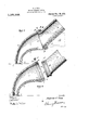
in position Ior assemblin F ig. -5, a plan view of a modified form 0 nozzle'with part of the handle, showing thenozzle at right angles to the axis of the handle in full'lines', inclined thereto, .in broken (10 lines; an Fig. 6, an axial section 'on line 66,. Fig; 5,. showing the handle rotated with its' axis'par'allel to the cleaning plane 1n full lines, and inclined obliquely thereto, in'brokenolines. Similar numerals refer to throughout the drawings.
V v similar parts illustrated a slot are located in the same lane and are adaptedto be presented against a carpet, floor or other objective surface 4, from whichlipsthe walls 5 of theinozzle diverge from the sides and converge.,from the ends upward'jand rearward and having the plane j lane. ,I v a Within the end portion of the. tubularstem 6 i s formed the cylindric socket or jour Y pal-bearing Shaving theannularrace-way 9 therein with an aperture '10 in one side turned home in the so that the inner-end l2 ofth'e plug is prop- Ierly shaped to form part. of therace-way. It will be understood that the cylindric socket S and the race-way 9 are formed c0.-' axial with-the end 7 of the headan'd are likewise located oblique to the li plane. The end 13 of the tubular h an le ,14 is;
ioblifquely beveled, preferably t e same1 angle from the handle-axis as the axis of the bearing socket -8 is inclined {from the li plan'e;--an'd on this end of the handle, t/hie is formed co-a'xial withthe main portion thereofl-is'formed the journal15 adapted to 0 neatly fit the nozzle socket 8, which journal is provided with the annular packing groove IG-"adj-acent to the 'en'd, 5nd" the annular 1 race-way 1 7 insidethe packing grcove,which 2 parts are all made co-axial with the beveled ,or assembling eases to form the swivel. joint, a suitable packing ringi18,
the .packing groove, the handle journal is 3 9 1Q balls-*rotatably:
telescopiad inthe nozr-ie socket until the racea,
- ways register,
19 are inserted the screw-plug 11 is inserted to complete the Joint. It is .evident that the swivel joint 'thus formed has no objectionable protruding or intruding parts; that the .bearing balls are protected from: dust and the packing ring 18; and thatthe after which the bearing balls bearin engage {the-parts together "without the use of any clampin' means, ad-
HstabIe or otherwise, the balls, the handle v freely'disen'gaged -z v L5 the modified. form of nozzle 1 illus- 9.? tbx'of theb t inghf 9, just the ..-a's 'fdescrib'ed for, the", forth of, nozzle ,n tl1e? 8e,0 vt nozzle,:1t= is evident that whines-mm tas a yrsezaxis, of; the nozzle, lea ame-e4 and, b""'ll)rokel1: a 1:, 1. te t-w n-p e e wi .i nne aridat right angles to'th'e through the. aperture 10, and
grit by I and that,- yremovihg, and nozzle may be trated in Figs'5 and 16, the end sections by t ecyl'i'ndric body section i I end rotatably en 0 mket or'journal beat;
socket. igurnal lfifon the en'd'of the straight handle 'th om p d yx j F'positiong; 'at"; right angles to, the" 58' shown by of tli'ei hozzlg; as shown-b '71 fl -P i v Fig 31mm. eda y l lines, in Fig. 6, which latter fi quite plainly that the nozzle can e inserted under any overhanging obstacle, ,as'an article of furniture,'which is not lower than the height of the nozzle itself. Furtherure shows more, it is .evident that, by rotating the handle fromits highest inclined position .to 1ts prone position, the nozzle will be deflected to an angle either on one side or the other from the axis-of the straight handle;
all of which can be done without tilting or removing the lips of the nozzle from the ob ect1ve surface. I claim:
- 1. A suction cleaning nozzle having along narrow slot ith coplanar lips and having a tubular ste end oblique to tubular handle with a 'cylindric socket in its the lip plane, and a straight having an oblique journal'on gaged in the socket.
, 2. A suction cleaning nozzle having a long narrow slot with coplanar lip's in its lowerhaving a. rearwardly extending side and tubular stem with a cylindric socket in its end oblique to. the lip plane, and a straight tubular handle "having an obli ue journal on ,itsfforward end rotatably 13g aged in the a 3. A suction cleaning nozzle having a long narrow .slotwith coplanar lips and havingl a tubular stem, and, a straight tubular han tabl swivel joint s formed bein the'lip' plane and to the axis of I ANDREW J.'TICE.- i i1 2m "Bar F. Born..-
there being a cylindric socket in the, end 0 a one tubularmember and ajournal on' the end of the other tubular member rota-' y the socket, the axis of the .obli'que to t e handle.
Priority Applications (1)
| Application Number | Priority Date | Filing Date | Title |
|---|---|---|---|
| US67731812A US1161908A (en) | 1912-02-13 | 1912-02-13 | Suction cleaning-nozzle. |
Applications Claiming Priority (1)
| Application Number | Priority Date | Filing Date | Title |
|---|---|---|---|
| US67731812A US1161908A (en) | 1912-02-13 | 1912-02-13 | Suction cleaning-nozzle. |
Publications (1)
| Publication Number | Publication Date |
|---|---|
| US1161908A true US1161908A (en) | 1915-11-30 |
Family
ID=3229944
Family Applications (1)
| Application Number | Title | Priority Date | Filing Date |
|---|---|---|---|
| US67731812A Expired - Lifetime US1161908A (en) | 1912-02-13 | 1912-02-13 | Suction cleaning-nozzle. |
Country Status (1)
| Country | Link |
|---|---|
| US (1) | US1161908A (en) |
Cited By (11)
| Publication number | Priority date | Publication date | Assignee | Title |
|---|---|---|---|---|
| US4309048A (en) * | 1978-12-14 | 1982-01-05 | Vorwerk & Co. Interholding Gmbh | Element for connecting an accessory instrument to a vacuum cleaner |
| US5323510A (en) * | 1993-07-09 | 1994-06-28 | Redding Glenn K | Vacuum cleaner having improved steering features |
| US5410776A (en) * | 1992-08-14 | 1995-05-02 | Schneider; Norman J. | Ceiling fan brush and adjustable angle tube vacuum connector for same |
| US5652996A (en) * | 1995-12-01 | 1997-08-05 | The Hoover Company | Hand held cleaner with swiveling nozzle |
| US6065183A (en) * | 1995-10-12 | 2000-05-23 | Nilfisk A/S | Connection element for a mouthpiece |
| US6125502A (en) * | 1995-10-12 | 2000-10-03 | Nilfisk A/S | Suction pipe for a suction cleaner |
| US6532622B2 (en) * | 2000-05-17 | 2003-03-18 | Daewoo Electronics Co., Ltd. | Brush head of vacuum cleaner |
| US8752241B2 (en) | 2010-10-06 | 2014-06-17 | Duepro Ag | Vacuum cleaner nozzle with magnetic lock |
| US10660494B1 (en) | 2011-10-31 | 2020-05-26 | James R. Alton | Vacuum cleaner |
| US11058267B2 (en) | 2016-04-27 | 2021-07-13 | Aktiebolaget Electrolux | Vacuum cleaner and vacuum cleaner system |
| US11534042B2 (en) | 2017-12-15 | 2022-12-27 | Aktiebolaget Electrolux | Vacuum cleaner |
-
1912
- 1912-02-13 US US67731812A patent/US1161908A/en not_active Expired - Lifetime
Cited By (12)
| Publication number | Priority date | Publication date | Assignee | Title |
|---|---|---|---|---|
| US4309048A (en) * | 1978-12-14 | 1982-01-05 | Vorwerk & Co. Interholding Gmbh | Element for connecting an accessory instrument to a vacuum cleaner |
| US5410776A (en) * | 1992-08-14 | 1995-05-02 | Schneider; Norman J. | Ceiling fan brush and adjustable angle tube vacuum connector for same |
| US5323510A (en) * | 1993-07-09 | 1994-06-28 | Redding Glenn K | Vacuum cleaner having improved steering features |
| US5584095A (en) * | 1993-07-09 | 1996-12-17 | Philips Electronics North America Corporation | Vacuum cleaner having improved steering features |
| US6065183A (en) * | 1995-10-12 | 2000-05-23 | Nilfisk A/S | Connection element for a mouthpiece |
| US6125502A (en) * | 1995-10-12 | 2000-10-03 | Nilfisk A/S | Suction pipe for a suction cleaner |
| US5652996A (en) * | 1995-12-01 | 1997-08-05 | The Hoover Company | Hand held cleaner with swiveling nozzle |
| US6532622B2 (en) * | 2000-05-17 | 2003-03-18 | Daewoo Electronics Co., Ltd. | Brush head of vacuum cleaner |
| US8752241B2 (en) | 2010-10-06 | 2014-06-17 | Duepro Ag | Vacuum cleaner nozzle with magnetic lock |
| US10660494B1 (en) | 2011-10-31 | 2020-05-26 | James R. Alton | Vacuum cleaner |
| US11058267B2 (en) | 2016-04-27 | 2021-07-13 | Aktiebolaget Electrolux | Vacuum cleaner and vacuum cleaner system |
| US11534042B2 (en) | 2017-12-15 | 2022-12-27 | Aktiebolaget Electrolux | Vacuum cleaner |
Similar Documents
| Publication | Publication Date | Title |
|---|---|---|
| US1161908A (en) | Suction cleaning-nozzle. | |
| US1318881A (en) | Vacuum-cleaner | |
| US1115989A (en) | Pipe-coupling. | |
| US2241771A (en) | Suction nozzle | |
| US1994616A (en) | Suction nozzle | |
| US1086367A (en) | Vacuum-cleaner tool. | |
| US2143845A (en) | Suction nozzle | |
| US2710204A (en) | Adjustable angle swivel elbow | |
| US491791A (en) | Flue-cleaner | |
| US1140992A (en) | Pneumatic suction-cleaner. | |
| US1039383A (en) | Suction-nozzle. | |
| US2230077A (en) | Vacuum cleaner | |
| US2025442A (en) | Suction nozzle | |
| US1104148A (en) | Cleaning-tool. | |
| US1072607A (en) | Pneumatic cleaning implement. | |
| US1110439A (en) | Suction cleaning-nozzle. | |
| US1060191A (en) | Vacuum cleaning-tool. | |
| US2659616A (en) | Vacuum cleaner implement and handle coupling | |
| US1474875A (en) | A cospokation oe | |
| US1543191A (en) | Flue cleaner | |
| US953729A (en) | Window-cleaner. | |
| US331782A (en) | Boiler-flue cleaner | |
| US1020104A (en) | Vacuum-sweeper. | |
| US918542A (en) | Swivel-coupling. | |
| US579108A (en) | Window-gleaming device |