US11615744B2 - Display device - Google Patents
Display device Download PDFInfo
- Publication number
- US11615744B2 US11615744B2 US17/141,808 US202117141808A US11615744B2 US 11615744 B2 US11615744 B2 US 11615744B2 US 202117141808 A US202117141808 A US 202117141808A US 11615744 B2 US11615744 B2 US 11615744B2
- Authority
- US
- United States
- Prior art keywords
- transistor
- electrode
- gate
- disposed
- display device
- Prior art date
- Legal status (The legal status is an assumption and is not a legal conclusion. Google has not performed a legal analysis and makes no representation as to the accuracy of the status listed.)
- Active, expires
Links
Images


Classifications
-
- H—ELECTRICITY
- H10—SEMICONDUCTOR DEVICES; ELECTRIC SOLID-STATE DEVICES NOT OTHERWISE PROVIDED FOR
- H10K—ORGANIC ELECTRIC SOLID-STATE DEVICES
- H10K59/00—Integrated devices, or assemblies of multiple devices, comprising at least one organic light-emitting element covered by group H10K50/00
- H10K59/10—OLED displays
- H10K59/12—Active-matrix OLED [AMOLED] displays
- H10K59/131—Interconnections, e.g. wiring lines or terminals
- H10K59/1315—Interconnections, e.g. wiring lines or terminals comprising structures specially adapted for lowering the resistance
-
- G—PHYSICS
- G09—EDUCATION; CRYPTOGRAPHY; DISPLAY; ADVERTISING; SEALS
- G09G—ARRANGEMENTS OR CIRCUITS FOR CONTROL OF INDICATING DEVICES USING STATIC MEANS TO PRESENT VARIABLE INFORMATION
- G09G3/00—Control arrangements or circuits, of interest only in connection with visual indicators other than cathode-ray tubes
- G09G3/20—Control arrangements or circuits, of interest only in connection with visual indicators other than cathode-ray tubes for presentation of an assembly of a number of characters, e.g. a page, by composing the assembly by combination of individual elements arranged in a matrix no fixed position being assigned to or needed to be assigned to the individual characters or partial characters
- G09G3/22—Control arrangements or circuits, of interest only in connection with visual indicators other than cathode-ray tubes for presentation of an assembly of a number of characters, e.g. a page, by composing the assembly by combination of individual elements arranged in a matrix no fixed position being assigned to or needed to be assigned to the individual characters or partial characters using controlled light sources
- G09G3/30—Control arrangements or circuits, of interest only in connection with visual indicators other than cathode-ray tubes for presentation of an assembly of a number of characters, e.g. a page, by composing the assembly by combination of individual elements arranged in a matrix no fixed position being assigned to or needed to be assigned to the individual characters or partial characters using controlled light sources using electroluminescent panels
- G09G3/32—Control arrangements or circuits, of interest only in connection with visual indicators other than cathode-ray tubes for presentation of an assembly of a number of characters, e.g. a page, by composing the assembly by combination of individual elements arranged in a matrix no fixed position being assigned to or needed to be assigned to the individual characters or partial characters using controlled light sources using electroluminescent panels semiconductive, e.g. using light-emitting diodes [LED]
- G09G3/3208—Control arrangements or circuits, of interest only in connection with visual indicators other than cathode-ray tubes for presentation of an assembly of a number of characters, e.g. a page, by composing the assembly by combination of individual elements arranged in a matrix no fixed position being assigned to or needed to be assigned to the individual characters or partial characters using controlled light sources using electroluminescent panels semiconductive, e.g. using light-emitting diodes [LED] organic, e.g. using organic light-emitting diodes [OLED]
- G09G3/3225—Control arrangements or circuits, of interest only in connection with visual indicators other than cathode-ray tubes for presentation of an assembly of a number of characters, e.g. a page, by composing the assembly by combination of individual elements arranged in a matrix no fixed position being assigned to or needed to be assigned to the individual characters or partial characters using controlled light sources using electroluminescent panels semiconductive, e.g. using light-emitting diodes [LED] organic, e.g. using organic light-emitting diodes [OLED] using an active matrix
- G09G3/3233—Control arrangements or circuits, of interest only in connection with visual indicators other than cathode-ray tubes for presentation of an assembly of a number of characters, e.g. a page, by composing the assembly by combination of individual elements arranged in a matrix no fixed position being assigned to or needed to be assigned to the individual characters or partial characters using controlled light sources using electroluminescent panels semiconductive, e.g. using light-emitting diodes [LED] organic, e.g. using organic light-emitting diodes [OLED] using an active matrix with pixel circuitry controlling the current through the light-emitting element
-
- G—PHYSICS
- G09—EDUCATION; CRYPTOGRAPHY; DISPLAY; ADVERTISING; SEALS
- G09F—DISPLAYING; ADVERTISING; SIGNS; LABELS OR NAME-PLATES; SEALS
- G09F9/00—Indicating arrangements for variable information in which the information is built-up on a support by selection or combination of individual elements
- G09F9/30—Indicating arrangements for variable information in which the information is built-up on a support by selection or combination of individual elements in which the desired character or characters are formed by combining individual elements
- G09F9/33—Indicating arrangements for variable information in which the information is built-up on a support by selection or combination of individual elements in which the desired character or characters are formed by combining individual elements being semiconductor devices, e.g. diodes
-
- G—PHYSICS
- G09—EDUCATION; CRYPTOGRAPHY; DISPLAY; ADVERTISING; SEALS
- G09G—ARRANGEMENTS OR CIRCUITS FOR CONTROL OF INDICATING DEVICES USING STATIC MEANS TO PRESENT VARIABLE INFORMATION
- G09G3/00—Control arrangements or circuits, of interest only in connection with visual indicators other than cathode-ray tubes
- G09G3/20—Control arrangements or circuits, of interest only in connection with visual indicators other than cathode-ray tubes for presentation of an assembly of a number of characters, e.g. a page, by composing the assembly by combination of individual elements arranged in a matrix no fixed position being assigned to or needed to be assigned to the individual characters or partial characters
- G09G3/22—Control arrangements or circuits, of interest only in connection with visual indicators other than cathode-ray tubes for presentation of an assembly of a number of characters, e.g. a page, by composing the assembly by combination of individual elements arranged in a matrix no fixed position being assigned to or needed to be assigned to the individual characters or partial characters using controlled light sources
- G09G3/30—Control arrangements or circuits, of interest only in connection with visual indicators other than cathode-ray tubes for presentation of an assembly of a number of characters, e.g. a page, by composing the assembly by combination of individual elements arranged in a matrix no fixed position being assigned to or needed to be assigned to the individual characters or partial characters using controlled light sources using electroluminescent panels
- G09G3/32—Control arrangements or circuits, of interest only in connection with visual indicators other than cathode-ray tubes for presentation of an assembly of a number of characters, e.g. a page, by composing the assembly by combination of individual elements arranged in a matrix no fixed position being assigned to or needed to be assigned to the individual characters or partial characters using controlled light sources using electroluminescent panels semiconductive, e.g. using light-emitting diodes [LED]
-
- H01L27/3262—
-
- H01L29/78696—
-
- H—ELECTRICITY
- H10—SEMICONDUCTOR DEVICES; ELECTRIC SOLID-STATE DEVICES NOT OTHERWISE PROVIDED FOR
- H10D—INORGANIC ELECTRIC SEMICONDUCTOR DEVICES
- H10D30/00—Field-effect transistors [FET]
- H10D30/60—Insulated-gate field-effect transistors [IGFET]
- H10D30/67—Thin-film transistors [TFT]
- H10D30/6757—Thin-film transistors [TFT] characterised by the structure of the channel, e.g. transverse or longitudinal shape or doping profile
-
- H—ELECTRICITY
- H10—SEMICONDUCTOR DEVICES; ELECTRIC SOLID-STATE DEVICES NOT OTHERWISE PROVIDED FOR
- H10D—INORGANIC ELECTRIC SEMICONDUCTOR DEVICES
- H10D86/00—Integrated devices formed in or on insulating or conducting substrates, e.g. formed in silicon-on-insulator [SOI] substrates or on stainless steel or glass substrates
- H10D86/40—Integrated devices formed in or on insulating or conducting substrates, e.g. formed in silicon-on-insulator [SOI] substrates or on stainless steel or glass substrates characterised by multiple TFTs
- H10D86/441—Interconnections, e.g. scanning lines
-
- H—ELECTRICITY
- H10—SEMICONDUCTOR DEVICES; ELECTRIC SOLID-STATE DEVICES NOT OTHERWISE PROVIDED FOR
- H10K—ORGANIC ELECTRIC SOLID-STATE DEVICES
- H10K59/00—Integrated devices, or assemblies of multiple devices, comprising at least one organic light-emitting element covered by group H10K50/00
- H10K59/10—OLED displays
- H10K59/12—Active-matrix OLED [AMOLED] displays
- H10K59/123—Connection of the pixel electrodes to the thin film transistors [TFT]
-
- H—ELECTRICITY
- H10—SEMICONDUCTOR DEVICES; ELECTRIC SOLID-STATE DEVICES NOT OTHERWISE PROVIDED FOR
- H10K—ORGANIC ELECTRIC SOLID-STATE DEVICES
- H10K59/00—Integrated devices, or assemblies of multiple devices, comprising at least one organic light-emitting element covered by group H10K50/00
- H10K59/10—OLED displays
- H10K59/12—Active-matrix OLED [AMOLED] displays
- H10K59/131—Interconnections, e.g. wiring lines or terminals
-
- G—PHYSICS
- G09—EDUCATION; CRYPTOGRAPHY; DISPLAY; ADVERTISING; SEALS
- G09G—ARRANGEMENTS OR CIRCUITS FOR CONTROL OF INDICATING DEVICES USING STATIC MEANS TO PRESENT VARIABLE INFORMATION
- G09G2300/00—Aspects of the constitution of display devices
- G09G2300/04—Structural and physical details of display devices
- G09G2300/0421—Structural details of the set of electrodes
- G09G2300/0426—Layout of electrodes and connections
-
- G—PHYSICS
- G09—EDUCATION; CRYPTOGRAPHY; DISPLAY; ADVERTISING; SEALS
- G09G—ARRANGEMENTS OR CIRCUITS FOR CONTROL OF INDICATING DEVICES USING STATIC MEANS TO PRESENT VARIABLE INFORMATION
- G09G2300/00—Aspects of the constitution of display devices
- G09G2300/04—Structural and physical details of display devices
- G09G2300/0421—Structural details of the set of electrodes
- G09G2300/043—Compensation electrodes or other additional electrodes in matrix displays related to distortions or compensation signals, e.g. for modifying TFT threshold voltage in column driver
-
- G—PHYSICS
- G09—EDUCATION; CRYPTOGRAPHY; DISPLAY; ADVERTISING; SEALS
- G09G—ARRANGEMENTS OR CIRCUITS FOR CONTROL OF INDICATING DEVICES USING STATIC MEANS TO PRESENT VARIABLE INFORMATION
- G09G2300/00—Aspects of the constitution of display devices
- G09G2300/08—Active matrix structure, i.e. with use of active elements, inclusive of non-linear two terminal elements, in the pixels together with light emitting or modulating elements
- G09G2300/0809—Several active elements per pixel in active matrix panels
- G09G2300/0819—Several active elements per pixel in active matrix panels used for counteracting undesired variations, e.g. feedback or autozeroing
-
- G—PHYSICS
- G09—EDUCATION; CRYPTOGRAPHY; DISPLAY; ADVERTISING; SEALS
- G09G—ARRANGEMENTS OR CIRCUITS FOR CONTROL OF INDICATING DEVICES USING STATIC MEANS TO PRESENT VARIABLE INFORMATION
- G09G2300/00—Aspects of the constitution of display devices
- G09G2300/08—Active matrix structure, i.e. with use of active elements, inclusive of non-linear two terminal elements, in the pixels together with light emitting or modulating elements
- G09G2300/0809—Several active elements per pixel in active matrix panels
- G09G2300/0842—Several active elements per pixel in active matrix panels forming a memory circuit, e.g. a dynamic memory with one capacitor
- G09G2300/0861—Several active elements per pixel in active matrix panels forming a memory circuit, e.g. a dynamic memory with one capacitor with additional control of the display period without amending the charge stored in a pixel memory, e.g. by means of additional select electrodes
-
- G—PHYSICS
- G09—EDUCATION; CRYPTOGRAPHY; DISPLAY; ADVERTISING; SEALS
- G09G—ARRANGEMENTS OR CIRCUITS FOR CONTROL OF INDICATING DEVICES USING STATIC MEANS TO PRESENT VARIABLE INFORMATION
- G09G2310/00—Command of the display device
- G09G2310/02—Addressing, scanning or driving the display screen or processing steps related thereto
- G09G2310/0243—Details of the generation of driving signals
- G09G2310/0251—Precharge or discharge of pixel before applying new pixel voltage
-
- G—PHYSICS
- G09—EDUCATION; CRYPTOGRAPHY; DISPLAY; ADVERTISING; SEALS
- G09G—ARRANGEMENTS OR CIRCUITS FOR CONTROL OF INDICATING DEVICES USING STATIC MEANS TO PRESENT VARIABLE INFORMATION
- G09G2310/00—Command of the display device
- G09G2310/02—Addressing, scanning or driving the display screen or processing steps related thereto
- G09G2310/0262—The addressing of the pixel, in a display other than an active matrix LCD, involving the control of two or more scan electrodes or two or more data electrodes, e.g. pixel voltage dependent on signals of two data electrodes
-
- G—PHYSICS
- G09—EDUCATION; CRYPTOGRAPHY; DISPLAY; ADVERTISING; SEALS
- G09G—ARRANGEMENTS OR CIRCUITS FOR CONTROL OF INDICATING DEVICES USING STATIC MEANS TO PRESENT VARIABLE INFORMATION
- G09G2320/00—Control of display operating conditions
- G09G2320/02—Improving the quality of display appearance
- G09G2320/0233—Improving the luminance or brightness uniformity across the screen
-
- G—PHYSICS
- G09—EDUCATION; CRYPTOGRAPHY; DISPLAY; ADVERTISING; SEALS
- G09G—ARRANGEMENTS OR CIRCUITS FOR CONTROL OF INDICATING DEVICES USING STATIC MEANS TO PRESENT VARIABLE INFORMATION
- G09G2320/00—Control of display operating conditions
- G09G2320/04—Maintaining the quality of display appearance
- G09G2320/043—Preventing or counteracting the effects of ageing
- G09G2320/045—Compensation of drifts in the characteristics of light emitting or modulating elements
-
- H—ELECTRICITY
- H10—SEMICONDUCTOR DEVICES; ELECTRIC SOLID-STATE DEVICES NOT OTHERWISE PROVIDED FOR
- H10D—INORGANIC ELECTRIC SEMICONDUCTOR DEVICES
- H10D30/00—Field-effect transistors [FET]
- H10D30/60—Insulated-gate field-effect transistors [IGFET]
- H10D30/67—Thin-film transistors [TFT]
- H10D30/6729—Thin-film transistors [TFT] characterised by the electrodes
- H10D30/673—Thin-film transistors [TFT] characterised by the electrodes characterised by the shapes, relative sizes or dispositions of the gate electrodes
- H10D30/6733—Multi-gate TFTs
-
- H—ELECTRICITY
- H10—SEMICONDUCTOR DEVICES; ELECTRIC SOLID-STATE DEVICES NOT OTHERWISE PROVIDED FOR
- H10D—INORGANIC ELECTRIC SEMICONDUCTOR DEVICES
- H10D86/00—Integrated devices formed in or on insulating or conducting substrates, e.g. formed in silicon-on-insulator [SOI] substrates or on stainless steel or glass substrates
- H10D86/40—Integrated devices formed in or on insulating or conducting substrates, e.g. formed in silicon-on-insulator [SOI] substrates or on stainless steel or glass substrates characterised by multiple TFTs
- H10D86/481—Integrated devices formed in or on insulating or conducting substrates, e.g. formed in silicon-on-insulator [SOI] substrates or on stainless steel or glass substrates characterised by multiple TFTs integrated with passive devices, e.g. auxiliary capacitors
-
- H—ELECTRICITY
- H10—SEMICONDUCTOR DEVICES; ELECTRIC SOLID-STATE DEVICES NOT OTHERWISE PROVIDED FOR
- H10D—INORGANIC ELECTRIC SEMICONDUCTOR DEVICES
- H10D86/00—Integrated devices formed in or on insulating or conducting substrates, e.g. formed in silicon-on-insulator [SOI] substrates or on stainless steel or glass substrates
- H10D86/40—Integrated devices formed in or on insulating or conducting substrates, e.g. formed in silicon-on-insulator [SOI] substrates or on stainless steel or glass substrates characterised by multiple TFTs
- H10D86/60—Integrated devices formed in or on insulating or conducting substrates, e.g. formed in silicon-on-insulator [SOI] substrates or on stainless steel or glass substrates characterised by multiple TFTs wherein the TFTs are in active matrices
-
- H—ELECTRICITY
- H10—SEMICONDUCTOR DEVICES; ELECTRIC SOLID-STATE DEVICES NOT OTHERWISE PROVIDED FOR
- H10K—ORGANIC ELECTRIC SOLID-STATE DEVICES
- H10K59/00—Integrated devices, or assemblies of multiple devices, comprising at least one organic light-emitting element covered by group H10K50/00
- H10K59/10—OLED displays
- H10K59/12—Active-matrix OLED [AMOLED] displays
- H10K59/121—Active-matrix OLED [AMOLED] displays characterised by the geometry or disposition of pixel elements
- H10K59/1213—Active-matrix OLED [AMOLED] displays characterised by the geometry or disposition of pixel elements the pixel elements being TFTs
Definitions
- the present disclosure relates to a display device, and more particularly, to a display device in which an electric field formed at a floating source/drain node of a dual transistor disposed between a source electrode and a gate electrode of a driving transistor.
- a display device may be a flat panel display device such as a liquid crystal display device, a field emission display device, or a light emitting display device. Since the light emitting display device, among flat panel display devices, includes light emitting elements by which each of the pixels in a display panel emits light by itself, it may display an image without a backlight unit providing light to the display panel.
- Each of the pixels in the display panel may include a plurality of thin film transistors.
- Each of the plurality of thin film transistors may be turned on based on a signal applied to a gate electrode.
- leakage current may flow by an electric field between the channel region and source/drain region of the thin film transistor, and the leakage current may deteriorate the luminance of a pixel. Therefore, a novel display device to reduce leakage current flowing through a thin film transistor is desired to prevent deterioration of the luminance of a pixel.
- aspects of the present disclosure are to provide a display device in which an electric field formed at a floating source/drain node of a dual transistor disposed between a source electrode and a gate electrode of a driving transistor, thereby reducing leakage current flowing through the dual transistor and preventing a drop in luminance of sub-pixels.
- a display device comprises: a substrate, and a plurality of sub-pixels disposed on the substrate and including a light emitting element and a sub-pixel circuit which drives the light emitting element.
- the sub-pixel circuit comprises: a driving transistor controlling a driving current flowing through the light emitting element, a first transistor and a second transistor connected in series and disposed between a first node, which is a drain electrode of the driving transistor, and a second node, which is a gate electrode of the driving transistor, to receive a same scan signal from a same scan line, and a gate auxiliary electrode disposed on a gate electrode of the first transistor or the second transistor.
- the gate auxiliary electrode is connected to the gate electrode of the first transistor or the second transistor.
- the gate auxiliary electrode may overlap a source electrode or a drain electrode of the first transistor or second transistor disposed between an active area of the first transistor and an active area of the second transistor in a thickness direction.
- the display device may further comprise: an active layer disposed on the substrate, and a first gate layer disposed on the active layer.
- An active area of each of the driving transistor, the first transistor, and the second transistor may be disposed in the active layer.
- a gate electrode of each of the driving transistor, the first transistor, and the second transistor may be disposed in the first gate layer.
- the display device may further comprise a second gate layer disposed on the first gate layer.
- the gate auxiliary electrode may be disposed in the second gate layer.
- the display device may further comprise: a gate insulating film insulating the gate electrode of each of the first and second transistors and the active area of each of the first and second transistors, and an interlayer insulating film disposed between the first gate layer and the second gate layer and including at least one contact hole.
- the gate auxiliary electrode may be connected to the gate electrode of the first transistor or the second transistor through the contact hole of the interlayer insulating film.
- the first transistor may include a source electrode connected to the first node and a drain electrode connected to the second transistor.
- the second transistor may include a source electrode connected to the drain electrode of the first transistor and a drain electrode connected to the second node.
- the gate auxiliary electrode may overlap the drain electrode of the first transistor or the source electrode of the second transistor in a thickness direction.
- the first transistor may further include a first doped area disposed between the active area of the first transistor and the source electrode of the first transistor, and a second doped area disposed between the active area of the first transistor and the drain electrode of the first transistor.
- the second transistor may further include a third doped area disposed between the active area of the second transistor and the source electrode of the second transistor, and a fourth doped area disposed between the active area of the second transistor and the drain electrode of the second transistor.
- Doping concentration of each of the first, second, third, and fourth doped areas may be higher than doping concentration of the active area of the first transistor or the second transistor.
- Doping concentration of each of the first, second, third, and fourth doped areas may be lower than doping concentration of each of the source electrode and drain electrode of the first transistor and the source electrode and drain electrode of the second transistor.
- the gate auxiliary electrode may overlap the second doped area of the first transistor or the third doped area of the second transistor in a thickness direction.
- the gate auxiliary electrode may overlap at least one of the second doped area and drain electrode of the first transistor and the third doped area and source electrode of the second transistor in a thickness direction.
- the sub-pixel circuit may further comprise a third transistor selectively supplying a data voltage to a third node which is a source electrode of the driving transistor.
- the first, second, and third transistors may receive the same scan signal.
- a display device comprises: a substrate, and a plurality of sub-pixels disposed on the substrate and including a light emitting element and a sub-pixel circuit which drives the light emitting element.
- the sub-pixel circuit comprises: a driving transistor controlling a driving current flowing through the light emitting element, a first transistor including a first electrode connected to a first node, which is a drain electrode of the driving transistor, and a second electrode selectively connected to a second node, which is a gate electrode of the driving transistor, a second transistor including a first electrode connected to the second electrode of the first transistor and a second electrode connected to the second node, and a gate auxiliary electrode disposed on a gate electrode of the first transistor or the second transistor and overlapping the second electrode of the first transistor or the first electrode of the second transistor in a thickness direction.
- the gate auxiliary electrode is connected to the gate electrode of the first transistor or the second transistor.
- the display device may further comprise: an active layer disposed on the substrate, and a first gate layer disposed on the active layer.
- An active area of each of the driving transistor, the first transistor, and the second transistor may be disposed in the active layer.
- a gate electrode of each of the driving transistor, the first transistor, and the second transistor may be disposed in the first gate layer.
- the display device may further comprise a second gate layer disposed on the first gate layer.
- the gate auxiliary electrode may be disposed in the second gate layer.
- the display device may further comprise: a gate insulating film insulating the gate electrode of each of the first and second transistors and the active area of each of the first and second transistors, and an interlayer insulating film disposed between the first gate layer and the second gate layer and including at least one contact hole.
- the gate auxiliary electrode may be connected to the gate electrode of the first transistor or the second transistor through the contact hole of the interlayer insulating film.
- the first transistor may further include a first doped area disposed between the active area of the first transistor and the first electrode of the first transistor, and a second doped area disposed between the active area of the first transistor and the second electrode of the first transistor.
- the second transistor may further include a third doped area disposed between the active area of the second transistor and the first electrode of the second transistor, and a fourth doped area disposed between the active area of the second transistor and the second electrode of the second transistor.
- the gate auxiliary electrode may overlap the second doped area of the first transistor or the third doped area of the second transistor in a thickness direction.
- the gate auxiliary electrode may overlap at least one of the second doped area and second electrode of the first transistor and the third doped area and first electrode of the second transistor in a thickness direction.
- FIG. 1 is a perspective view of a display device according to an embodiment
- FIG. 2 is an exploded perspective view of a display device according to an embodiment
- FIG. 3 is a plan view of a display panel according to an embodiment
- FIG. 4 is a block diagram illustrating a display panel and a display driver according to an embodiment
- FIG. 5 depicts a sub-pixel circuit of a sub-pixel according to an embodiment
- FIG. 6 is a waveform diagram of signals transmitted to the sub-pixel illustrated in FIG. 5 ;
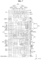
- FIG. 7 is a plan view illustrating an example of the sub-pixel illustrated in FIG. 5 ;
- FIG. 8 is a cross-sectional view taken along line I-I′ in FIG. 7 ;
- FIG. 9 is an enlarged view of the area A 1 in FIG. 7 ;
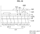
- FIG. 10 is a cross-sectional view taken along line II-II′ in FIG. 9 ;
- FIG. 11 is a plan view illustrating another example of the sub-pixel illustrated in FIG. 5 ;
- FIG. 12 is an enlarged view of the area A 2 in FIG. 11 ;
- FIG. 13 is a cross-sectional view taken along line III-III′ in FIG. 12 ;
- FIG. 14 is a plan view illustrating another example of the sub-pixel illustrated in FIG. 5 ;
- FIG. 15 is an enlarged view of the area A 3 in FIG. 14 ;
- FIG. 16 is a cross-sectional view taken along line IV-IV′ in FIG. 15 .
- the illustrated example embodiments are to be understood as providing example features of varying detail of some ways in which the inventive concepts may be implemented in practice. Therefore, unless otherwise specified, the features, components, modules, layers, films, panels, regions, and/or aspects, etc. (hereinafter individually or collectively referred to as “elements”), of the various embodiments may be otherwise combined, separated, interchanged, and/or rearranged without departing from the inventive concepts.
- an element such as a layer
- it may be directly on, connected to, or coupled to the other element or layer or intervening elements or layers may be present.
- an element or layer is referred to as being “directly on,” “directly connected to,” or “directly coupled to” another element or layer, there are no intervening elements or layers present.
- the term “connected” may refer to physical, electrical, and/or fluid connection, with or without intervening elements.
- the X-axis, the Y-axis, and the Z-axis are not limited to three axes of a rectangular coordinate system, such as the x, y, and z axes, and may be interpreted in a broader sense.
- the X-axis, the Y-axis, and the Z-axis may be perpendicular to one another, or may represent different directions that are not perpendicular to one another.
- “at least one of X, Y, and Z” and “at least one selected from the group consisting of X, Y, and Z” may be construed as X only, Y only, Z only, or any combination of two or more of X, Y, and Z, such as, for instance, XYZ, XYY, YZ, and ZZ.
- the term “and/or” includes any and all combinations of one or more of the associated listed items.
- Spatially relative terms such as “beneath,” “below,” “under,” “lower,” “above,” “upper,” “over,” “higher,” “side” (e.g., as in “sidewall”), and the like, may be used herein for descriptive purposes, and, thereby, to describe one elements relationship to another element(s) as illustrated in the drawings.
- Spatially relative terms are intended to encompass different orientations of an apparatus in use, operation, and/or manufacture in addition to the orientation depicted in the drawings. For example, if the apparatus in the drawings is turned over, elements described as “below” or “beneath” other elements or features would then be oriented “above” the other elements or features.
- the example term “below” can encompass both an orientation of above and below.
- the apparatus may be otherwise oriented (e.g., rotated 90 degrees or at other orientations), and, as such, the spatially relative descriptors used herein interpreted accordingly.
- example embodiments are described herein with reference to sectional and/or exploded illustrations that are schematic illustrations of idealized example embodiments and/or intermediate structures. As such, variations from the shapes of the illustrations as a result, for example, of manufacturing techniques and/or tolerances, are to be expected. Thus, example embodiments disclosed herein should not necessarily be construed as limited to the particular illustrated shapes of regions, but are to include deviations in shapes that result from, for instance, manufacturing. In this manner, regions illustrated in the drawings may be schematic in nature and the shapes of these regions may not reflect actual shapes of regions of a device and, as such, are not necessarily intended to be limiting.
- each block, unit, and/or module may be implemented by dedicated hardware, or as a combination of dedicated hardware to perform some functions and a processor (e.g., one or more programmed microprocessors and associated circuitry) to perform other functions.
- a processor e.g., one or more programmed microprocessors and associated circuitry
- each block, unit, and/or module of some example embodiments may be physically separated into two or more interacting and discrete blocks, units, and/or modules without departing from the scope of the inventive concepts.
- the blocks, units, and/or modules of some example embodiments may be physically combined into more complex blocks, units, and/or modules without departing from the scope of the inventive concepts.
- FIG. 1 is a perspective view of a display device according to an embodiment
- FIG. 2 is an exploded perspective view of a display device according to an embodiment.
- a display device 10 includes a cover window 100 , a display panel 300 , a bracket 600 , a main circuit board 700 , and a lower cover 900 .
- the “on”, “over”, “top”, “upper side”, or “upper surface” refers to an upward direction with respect to the display device, that is, a Z-axis direction, 10
- the “beneath”, “under”, “bottom”, “lower side”, or “lower surface” refers to a downward direction with respect to the display device 10 , that is, a direction opposite to the Z-axis direction.
- “left”, “right”, “upper”, and “lower” refer to directions when the display device 10 is viewed in a plan view.
- left refers to a direction opposite to the X-axis direction
- right refers to the X-axis direction
- upper refers to the Z-axis direction
- lower refers to a direction opposite to the Z-axis direction.
- the display device 10 which is a device for displaying a moving image or a still image, may be used as a display screen of various products such as televisions, notebooks, monitors, billboards, internet of things (IOTs) as well as portable electronic appliances such as mobile phones, smart phones, tablet personal computers (tablet PCs), smart watches, watch phones, mobile communication terminals, electronic notebooks, electronic books, portable multimedia players (PMPs), navigators, and ultra mobile PCs (UMPCs).
- IOTs internet of things
- portable electronic appliances such as mobile phones, smart phones, tablet personal computers (tablet PCs), smart watches, watch phones, mobile communication terminals, electronic notebooks, electronic books, portable multimedia players (PMPs), navigators, and ultra mobile PCs (UMPCs).
- the display device 10 may be formed in a rectangular shape viewed in a plan view.
- the display device 10 may have a rectangular planar shape having short sides in the first direction (X-axis direction) and long sides in the second direction (Y-axis direction) as shown in FIGS. 1 and 2 .
- the corner where the short side in the first direction (X-axis direction) meets the long side in the second direction (Y-axis direction) may be formed to have a right angle shape or a round shape having a predetermined curvature.
- the planar shape of the display device 10 is not limited to a rectangular shape, and may be formed in another polygonal shape, circular shape, or elliptical shape.
- the cover window 100 may be disposed on the display panel 300 to cover the upper surface of the display panel 300 .
- the cover window 100 may protect the upper surface of the display panel 300 .
- the cover window 100 may include a first light transmitting portion DA 1 and a second light transmitting portion DA 2 corresponding to the display panel 300 , and a light blocking area LBA corresponding to an area other than the display panel 300 .
- the second light transmitting portion DA 2 may be disposed at one side of the first light transmitting portion DA 1 , for example, the upper side thereof as shown in FIGS. 1 and 2 .
- the light blocking area LBA may be formed to be opaque. Alternatively, the light blocking area LBA may be formed as a decorative layer having a pattern that can be seen to a user when an image is not displayed.
- the display panel 300 may be disposed under the cover window 100 . Thus, the image of the display panel 300 may be seen from the upper surface of the display device 10 through the cover window 100 .
- the display panel 300 may be a light emitting display panel including a light emitting element.
- Examples of the display panel 300 may include an organic light emitting display panel using an organic light emitting diode including an organic light emitting layer, an ultra-micro light emitting diode display panel using an ultra-micro light emitting diode (ultra-micro LED, a quantum dot light emitting diode display panel using a quantum dot light emitting diode including a quantum dot light emitting layer, and an inorganic light emitting display panel using an inorganic light emitting diode including an inorganic semiconductor.
- the display panel 300 is an organic light emitting display panel.
- the display panel 300 may include a main area MA and a second non-display area PA protruding from one side of the main area MA.
- the main area MA may include a first display area MDA, a second display area SDA, and a first non-display area NDA.
- the first display area MDA may be disposed to overlap a first light transmitting portion DA 1 of the cover window 100 .
- the second display area SDA may be disposed to overlap a second light transmitting portion DA 2 of the cover window 100 .
- the second display area SDA may be disposed at one side of the first display area MDA, for example, the upper side thereof as shown in FIG. 2 , but the present disclosure is not limited.
- the second display area SDA may be disposed to be surrounded by the first display area MDA, and may be disposed adjacent to the corners of the display panel 300 .
- the display panel 300 includes one second display area SDA, the present disclosure is not limited.
- the display panel 300 may include a plurality of second display areas SDA.
- Each of the first display area MDA and the second display area SDA may include a plurality of pixels, scan lines, data lines, and a power supply line.
- Each of the plurality of pixels includes a plurality of sub-pixels. The plurality of sub-pixels are connected to the scan lines, the data lines, and the power supply line.
- the first non-display area NDA may be defined as an edge area of the display panel 300 .
- the first non-display area NDA may include a scan driver for applying scan signals to the scan lines, and link lines connecting the data lines to a display driver 310 .
- the second non-display area PA may protrude from one side of the main area MA. As shown in FIG. 2 , the second non-display area PA may protrude from the lower side of the first display area MDA. For example, the length of the second non-display area PA in the first direction (X-axis direction) may be smaller than the length of the main area MA in the first direction (X-axis direction).
- the second non-display area PA may include a bending area and a pad area.
- the pad area may be disposed at one side of the bending area, and the main area MA may be disposed at the other side of the bending area.
- the pad area may be disposed at the lower side of the bending area, and the main area MA may be disposed at the upper side of the bending area.
- the display panel 300 may be flexibly formed to be curved, warped, bent, folded, or rolled. Therefore, the display panel 300 may be bent in the thickness direction (Z-axis direction) in the bending area.
- the display panel 300 may include a display driver 310 , a circuit board 320 , a power supply unit 330 , and a touch driver 340 .
- the display driver 310 may output signals and voltages for driving the display panel 300 .
- the display driver 310 may supply a data voltage to a data line.
- the display driver 310 may supply a power supply voltage to a power supply line, and may supply a scan control signal to a scan driver.
- the circuit board 320 may be attached onto the pad using an anisotropic conductive film (ACF).
- ACF anisotropic conductive film
- the lead lines of the circuit board 320 may be electrically connected to the pads of the display panel 300 .
- the circuit board 320 may be a flexible printed circuit board (FPCB), a printed circuit board (PCB), or a flexible film such as a chip on film (COF).
- the power supply unit 330 may be disposed on the circuit board 320 to supply driving voltages to the display driver 310 and the display panel 300 . Specifically, the power supply unit 330 may generate a first driving voltage and supply the first driving voltage to a first driving voltage line, and may generate a second driving voltage and supply the second driving voltage to a second driving voltage line. Further, the power supply unit 330 may generate a third driving voltage and supply the third driving voltage to a cathode electrode of an organic light emitting diode of each of the first and second sub-pixels.
- the first and second driving voltages may be high-potential voltages for driving a light emitting element, for example, an organic light emitting diode, and the second driving voltage may be a high-potential voltage greater than the first driving voltage.
- the third driving voltage may be a low-potential voltage for driving the organic light emitting diode.
- the touch driver 340 may be disposed on the circuit board 320 to measure capacitances of touch electrodes. For example, the touch driver 340 may determine a user's touch and a user's touch position on the basis of the change in capacitance of the touch electrodes.
- the user's touch means that an object such as a user's finger or pen directly contacts one surface of the display device 10 disposed on s touch sensing layer.
- the touch driver 340 may determine the user's touch position by distinguishing a portion where a user touch occurs from a portion where the user touch does not occur among the plurality of touch electrodes.
- the bracket 600 may be disposed under the display panel 300 .
- a first camera hole CMH 1 into which a first camera sensor 720 is inserted is defined in the bracket 600 .
- a battery hole BH in which a battery is disposed, and a cable hole CAH through which a cable connected to the display driver 310 or the circuit board 320 passes, and a sensor hole SH in which sensor devices 740 , 750 , 760 , and 770 are disposed are also defined in the bracket 600 .
- the bracket 600 may be formed so as not to overlap the second display area SDA of the display panel 300 .
- the main circuit board 700 and a battery 790 may be disposed under the bracket 600 .
- the main circuit board 700 may be a printed circuit board or a flexible printed circuit board.
- the main circuit board 700 may include a main processor 710 , a first camera sensor 720 , a main connector 730 , and a plurality of sensor devices 740 , 750 , 760 , and 770 .
- the first camera sensor 720 may be disposed on both the upper surface and lower surface of the main circuit board 700
- the main processor 710 may be disposed on the upper surface of the main circuit board 700
- the main connector 730 may be disposed on the lower surface of the main circuit board 700 .
- the plurality of sensor devices 740 , 750 , 760 , 770 may be disposed on the upper surface of the main circuit board 700 .
- the main processor 710 may control all the functions of the display device 10 .
- the main processor 710 may output digital video data to the display driver 310 such that the display panel 300 displays an image.
- the main processor 710 may receive touch data from the touch driver 340 , determine the touch coordinates of a user, and then execute an application indicated by an icon displayed at the touch coordinates of the user.
- the main processor 710 may control the display device 10 according to sensor signals input from the plurality of sensor devices 740 , 750 , 760 , and 770 . For example, the main processor 710 may determine whether an object is located close to the upper surface of the display device 10 according to a proximity sensor signal input from the proximity sensor 740 . When the object is located close to the upper surface of the display device 10 in the call mode, the main processor 710 may not execute an application indicated by an icon displayed at the touch coordinates even if a touch is executed by a user.
- the main processor 710 may determine the brightness of the upper surface of the display device 10 according to an illumination sensor signal input from the illumination sensor 750 .
- the main processor 710 may adjust the luminance of an image displayed by the display panel 300 according to the brightness of the upper surface of the display device 10 .
- the main processor 710 may determine whether an iris image of the user is the same as the iris image previously stored in the memory according to an iris sensor signal input from the iris sensor 760 . When the iris image of the user is the same as the iris image previously stored in the memory, the main processor 710 may unlock the display device 10 and display a home screen on the display panel 300 .
- the first camera sensor 720 may process an image frame such as a still image or a moving image obtained by the image sensor, and output the processed image frame to the main processor 710 .
- the first camera sensor 720 may be a CMOS image sensor or a CCD sensor, but is not necessarily limited.
- the first camera sensor 720 may be exposed to the lower surface of the lower cover 900 by the second camera hole CMH 2 , and may photograph an object or a background disposed under the display device 10 .
- the cable having passed through the cable hole CAH of the bracket 600 may be connected to the main connector 730 .
- the main circuit board 700 may be electrically connected to the display driver 310 or the circuit board 320 .
- the plurality of sensor devices may include a proximity sensor 740 , an illumination sensor 750 , an iris sensor 760 , and a second camera sensor 770 .
- the proximity sensor 740 may detect whether an object is located close to the upper surface of the display device 10 .
- the proximity sensor 740 may include a light source that outputs light and a light receiver that receives light reflected by the object.
- the proximity sensor 740 may determine whether an object located close to the upper surface of the display device 10 exists according to the amount of light reflected by the object.
- the proximity sensor 740 may generate a proximity sensor signal depending on whether the object located close to the upper surface of the display device 10 exists, and may output the proximity signal to the main processor 710 .
- the illumination sensor 750 may detect the brightness of the upper surface of the display device.
- the illumination sensor 750 may include a resistor whose resistance value changes depending on the brightness of incident light.
- the illumination sensor 750 may determine the brightness of the upper surface of the display device depending on the resistance value of the resistor. Since the illumination sensor 750 is disposed to overlap the sensor hole SH, the second display area SDA of the display panel 300 , and the second light transmitting portion DA 2 of the cover window 100 in the thickness direction (Z-axis direction) of the display panel 300 , the illumination sensor 750 may generate an illumination sensor signal depending on the brightness of the upper surface of the display device, and may output the illumination sensor signal to the main processor 710 .
- the iris sensor 760 may detect whether an image of a user's iris is the same as the iris image previously stored in the memory.
- the iris sensor 760 may generate an iris sensor signal depending on whether the image of the user's iris is the same as the iris image previously stored in the memory, and may generate the iris sensor signal to the main processor 710 .
- the second camera sensor 770 may process an image frame such as a still image or a moving image obtained by the image sensor, and output the processed image frame to the main processor 710 .
- the second camera sensor 770 may be a CMOS image sensor or a CCD sensor, but is not necessarily limited.
- the number of pixels in the second camera sensor 770 may be smaller than the number of pixels in the first camera sensor 720
- the size of the second camera sensor 770 may be smaller than the size of the first camera sensor 720 .
- the second camera sensor 770 may photograph an object or a background disposed on the display device 10 .
- the battery 790 may be disposed not to overlap the main circuit board 700 in the third direction (Z-axis direction). That is, the battery 790 is aligned with the battery hole BH of the bracket 600 so that the battery 790 may overlap the battery hole BH of the bracket 600 .
- the main circuit board 700 may include a mobile communication module capable of transmitting and receiving a radio signal to/from at least one of a base station, an external terminal, and a server.
- the radio signal may include various types of data depending on a voice signal, a video call signal, or a text/multimedia message transmission/reception.
- the lower cover 900 may be disposed under the main circuit board 700 and the battery 790 .
- the lower cover 900 may be fixedly engaged to the bracket 600 .
- the lower cover 900 may form a lower surface appearance of the display device 10 .
- the lower cover 900 may be made of plastic, metal, or a combination of plastic and metal.
- a second camera hole CMH 2 through which the lower surface of the first camera sensor 720 is exposed is defined in the lower cover 900 .
- the position of the first camera sensor 720 and the positions of the first and second camera holes CMH 1 and CMH 2 corresponding to the first camera sensor 720 are limited to the embodiment shown in FIG. 2 .
- FIG. 3 is a plan view of a display panel according to an embodiment
- FIG. 4 is a block diagram illustrating a display panel and a display driver according to an embodiment.
- the display panel 300 may include a first display area MDA, a second display area SDA, and a first non-display area NDA.
- the first display area MDA includes a plurality of first sub-pixels SP 1 , driving voltage lines VDDL connected to the plurality of first sub-pixels SP 1 , scan lines SL, and emission control lines EML, and data lines DL.
- Each of the plurality of first sub-pixels SP 1 may be connected to at least one scan line SL, at least one data line DL, at least one emission control line EML, and at least one driving voltage line VDDL. Although it is shown in FIGS. 3 and 4 that each of the plurality of first sub-pixels SP 1 may be connected to two scan lines SL, one data line DL, one emission control line EML, and one driving voltage line VDDL, the present disclosure is not limited. For example, each of the plurality of first sub-pixels SP 1 may be connected to three or more scan lines SL.
- Each of the plurality of first sub-pixels SP 1 may include a driving transistor, at least one switching transistor, a light emitting element, and a capacitor.
- the first sub-pixels SP 1 may receive a driving voltage VDD through driving voltage line VDDL.
- the driving voltage VDD may be a high-potential voltage for driving the light emitting elements of the plurality of first sub-pixels SP 1 .
- the scan lines SL and the emission control lines EML may extend in the first direction (X-axis direction), and may be spaced apart from each other in the second direction (Y-axis direction) crossing the first direction (X-axis direction).
- the data lines DL and the driving voltage lines VDDL may extend in the second direction (Y-axis direction), and may be spaced apart from each other in the first direction (X-axis direction).
- the second display area SDA may include second sub-pixels SP 2 , driving voltage lines VDDL connected to the plurality of second sub-pixels SP 2 , scan lines SL, and emission control lines EML, and data lines DL.
- Each of the plurality of second sub-pixels SP 2 may be connected to at least one scan line SL, at least one data line DL, at least one emission control line EML, and at least one driving voltage line VDDL. Although it is shown in FIGS. 3 and 4 that each of the plurality of second sub-pixels SP 2 may be connected to two scan lines SL, one data line DL, one emission control line EML, and one driving voltage line VDDL, the present disclosure is not limited. For example, each of the second sub-pixels SP 2 may be connected to three or more scan lines SL.
- Each of the second sub-pixels SP 2 may include a driving transistor, at least one switching transistor, a light emitting element, and a capacitor.
- the second sub-pixels SP 2 may receive a driving voltage VDD through the driving voltage lines VDDL.
- the driving voltage VDD may be a high-potential voltage for driving the light emitting elements of the second sub-pixels SP 2 .
- the number of first sub-pixels SP 1 per unit area of the first display area MDA may be larger than the number of second sub-pixels SP 2 per unit area of the second display area SDA.
- the first display area MDA is an area for displaying an image, which is a main function of the display device 10 , and the first sub-pixels SP 1 may be densely arranged in the first display area MDA.
- the second display area SDA may include a pixel area in which the second sub-pixels SP 2 are arranged, and a transmission area that transmits light. Accordingly, as the area of the transmission area of the second display area SDA increases, the number of second sub pixels SP 2 per unit area may be smaller than the number of first sub pixels SP 1 per unit area.
- the first non-display area NDA may be defined as a remaining area of the display panel 300 that is not part of the first display area MDA or the second display area SDA.
- the first non-display area may include a scan driver 410 for applying scan signals to the scan lines SL, an emission control driver 420 for applying emission signals to the emission control lines EML, fan-out lines FL for connecting the data lines DL and the display driver 310 , and pads DP connected to the circuit board 320 .
- the display driver 310 and the pads DP may be disposed in the pad area of the display panel 300 .
- the pads DP may be disposed closer to one edge of the pad area than the display driver 310 .
- the display driver 310 may include a timing controller 311 and a data driver 312 .
- the timing controller 311 may receive digital video data DATA and timing signals from the circuit board 320 .
- the timing controller 311 may generate a scan control signal SCS on the basis of the timing signals to control the operation timing of the scan driver 410 , may generate an emission control signal ECS on the basis of the timing signals to control the operation timing of the emission control driver 420 , and may generate a data control signal DCS on the basis of the timing signals to control the operation timing of the data driver 312 .
- the timing controller 311 may output the scan control signal SCS to the scan driver 410 through the first scan control line SCL 1 .
- the timing controller 311 may output the emission control signal ECS to the emission control driver 420 through the second scan control line SCL 2 .
- the timing controller 311 may supply the digital video data DATA and the data control signal DCS to the data driver 312 .
- the data driver 312 may convert the digital video data DATA into analog data voltages and output the analog data voltages to the data lines DL through the fan-out lines FL.
- the scan signals of the scan driver 410 may select pixels SP to which the data voltage is to be supplied, and the data driver 312 may supply the data voltages to the selected pixels SP.
- “Pixels SP,” as used herein, is intended to mean either the first sub-pixel SP 1 or the second sub-pixel SP 2 .
- the scan driver 410 may be disposed outside one side of the first display area MDA and one side of the second display area SDA or at one side of the first non-display area NDA.
- the emission control driver 420 may be disposed outside the other side of the first display area MDA and the other side of the second display area SDA or at the other side of the first non-display area NDA.
- both the scan driver 410 and the emission control driver 420 may be disposed outside one side of the first display area MDA and one side of the second display area SDA.
- the scan driver 410 may include a plurality of thin film transistors for generating scan signals based on the scan control signal SCS
- the emission control driver 420 may include a plurality of thin film transistors for generating emission signals based on the emission control signal ECS.
- the thin film transistors of the scan driver 410 and the thin film transistors of the emission control driver 420 may be formed on the same layer as the thin film transistors of the first and second sub-pixels SP 1 and SP 2 , respectively.
- FIG. 5 depicts a sub-pixel circuit of a sub-pixel according to an embodiment
- FIG. 6 is a waveform diagram of signals transmitted to the sub-pixel illustrated in FIG. 5
- the sub-pixel SP illustrated in FIG. 5 may correspond to the first sub-pixel SP 1 or the second sub-pixel SP 2 illustrated in FIGS. 3 and 4 .
- the display panel 300 may include a plurality of sub-pixels SP arranged along a k-th row (k is a natural number) and a j-th column (j is a natural number).
- the first display area MDA of the display panel 300 may include first sub-pixels SP 1
- the second display area SDA thereof may include second sub-pixels SP 2 .
- the first sub-pixels SP 1 or the second sub-pixels SP 2 arranged in the k-th row may be connected to the k-th scan line SLk, the k-lth scan line SLk- 1 , the emission control line EML, the data line DL, the driving voltage line VDDL, and the initialization voltage line VIL.
- Each of the first sub-pixels SP 1 and each of the second sub-pixels SP 2 may include a driving transistor DT, a light emitting element EL, a plurality of switching elements, and a first capacitor C 1 .
- the switching elements may include first to sixth transistors ST 1 , ST 2 , ST 3 , ST 4 , ST 5 , and ST 6 .
- the driving transistor DT may include a gate electrode, a source electrode, and a drain electrode.
- the drain electrode of the driving transistor DT may be connected to a first node N 1
- the gate electrode of the driving transistor DT may be connected to a second node N 2
- the source electrode of the driving transistor DT may be connected to a third node N 3 .
- the driving transistor DT controls a source-drain current Isd (hereinafter, referred to as “driving current”) on the basis of the data voltage (hereinafter, indicated as “Vdata”) applied to the gate electrode.
- k′ refers to a proportional coefficient determined by the structure and physical characteristics of the driving transistor DT
- Vsg refers to a source-gate voltage of the driving transistor DT
- Vth refers to a threshold voltage of driving transistor DT.
- the light emitting element EL may receive the driving current Isd to emit light.
- the emission amount or luminance of the light emitting element EL may be proportional to the intensity of the driving current Isd.
- the light emitting element EL may be an organic light emitting diode including an anode electrode, a cathode electrode, and an organic light emitting layer disposed between the anode electrode and the cathode electrode.
- the light emitting element EL may be an inorganic light emitting element including an anode electrode, a cathode electrode, and an inorganic semiconductor layer disposed between the anode electrode and the cathode electrode.
- the light emitting element EL may be a quantum dot light emitting element including an anode electrode, a cathode electrode, and a quantum dot light emitting layer disposed between the anode electrode and the cathode electrode.
- the light emitting element EL may be a micro light emitting diode.
- An anode electrode of the light emitting element EL may be connected to a fourth node N 4 .
- the anode electrode of the light emitting element EL may be connected to a drain electrode of the fifth transistor ST 5 and a drain electrode of the sixth transistor T 6 through the fourth node N 4 .
- a cathode electrode of the light emitting element EL may be connected to a low-potential line VSSL.
- a parasitic capacitance may be formed between the anode electrode and cathode electrode of the light emitting element EL.
- the first transistor ST 1 may be turned on by a scan signal SCk of the scan line SLk of the corresponding stage to connect the first node N 1 , which is a drain electrode of the driving transistor DT, to the second node N 2 , which is a gate electrode of the driving transistor DT.
- the first transistor ST 1 may be a dual transistor including a first-first transistor ST 1 - 1 and a first-second transistor ST 1 - 2 .
- the gate electrode of the first-first transistor ST 1 - 1 may be connected to the scan line SLk of the corresponding stage, the source electrode of the first-first transistor ST 1 - 1 may be connected to the first node N 1 , and the drain electrode of the first-first transistor ST 1 - 1 may be connected to the source electrode of the first-second transistor ST 1 - 2 .
- the gate electrode of the first-second transistor ST 1 - 2 may be connected to the scan line SLk of the corresponding stage, the source electrode of the first-second transistor ST 1 - 2 may be connected to the drain electrode of the first-first transistor ST 1 - 1 , and the drain electrode of the first-second transistor ST 1 - 2 may be connected to the second node N 2 .
- the second transistor ST 2 may be turned on by a scan signal SCk- 1 of the scan line SLk- 1 of the previous stage to connect the initialization voltage line VIL to the second node N 2 , which is a gate electrode of the driving transistor DT.
- the second transistor ST 2 may be a dual transistor including a second-first transistor ST 2 - 1 and a second-second transistor ST 2 - 2 .
- the second-first transistor ST 2 - 1 and the second-second transistor ST 2 - 2 are turned on based on the scan signal SCk- 1 of the previous stage to discharge the gate electrode of the driving transistor DT with the initialization voltage VI.
- the gate electrode of the second-first transistor ST 2 - 1 may be connected to the scan line SLk of the previous stage, the source electrode of the second-first transistor ST 2 - 1 may be connected to the initialization voltage line VIL, and the drain electrode of the second-first transistor ST 2 - 1 may be connected to the source electrode of the second-second transistor ST 2 - 2 .
- the gate electrode of the second-second transistor ST 2 - 2 may be connected to the scan line SLk- 1 of the previous stage, the source electrode of the second-second transistor ST 2 - 2 may be connected to the drain electrode of the second-first transistor ST 2 - 1 , and the drain electrode of the second-second transistor ST 2 - 2 may be connected to the second node N 2 .
- the third transistor ST 3 may be turned on by a scan signal SCk of the scan line SLk of the corresponding stage to connect the data line DL to the third node N 3 , which is a source electrode of the driving transistor DT.
- the third transistor ST 3 may be turned on based on the scan signal SCk to supply the data voltage Vdata to the third node N 3 .
- the gate electrode of the third transistor ST 3 may be connected to the scan line SLk of the corresponding stage, the source electrode thereof may be connected to the data line DL, and the drain electrode thereof may be connected to the third node N 3 .
- the drain electrode of the third transistor ST 3 may be connected to the source electrode of the driving transistor DT and the drain electrode of the fourth transistor ST 4 through the third node N 3 .
- the fourth transistor ST 4 may be turned on by an emission signal EM of the emission control line to connect the driving voltage line DL to the third node N 3 , which is a source electrode of the driving transistor DT.
- the gate electrode of the fourth transistor ST 4 may be connected to the emission control line EML
- the source electrode of the fourth transistor ST 4 may be connected to the driving voltage line VDDL
- the drain electrode of the fourth transistor ST 4 may be connected to the third node N 3 .
- the drain electrode of the fourth transistor ST 4 may be connected to the source electrode of the driving transistor DT and the drain electrode of the third transistor ST 3 through the third node N 3 .
- the fifth transistor ST 5 may be turned on by the emission signal EM of the emission control line EML to connect the first node N 1 , which is a drain electrode of the driving transistor DT, to the fourth node N 4 , which is an anode electrode of the light emitting element EL.
- the gate electrode of the fifth transistor ST 5 may be connected to the emission control line EML, the source electrode thereof may be connected to the first node N 1 , and the drain electrode of the fifth transistor ST 5 may be connected to the fourth node N 4 .
- the source electrode of the fifth transistor ST 5 may be connected to the drain electrode of the driving transistor DT and the source electrode of the first-first transistor ST 1 - 1 through the first node N 1 .
- the drain electrode of the fifth transistor ST 5 may be connected to the anode electrode of the light emitting element EL and the drain electrode of the sixth transistor ST 6 through the fourth node N 4 .
- the driving current may be supplied to the light emitting element EL.
- the sixth transistor ST 6 may be turned on by a scan signal SCk- 1 of the scan line SLk of the corresponding stage to connect the initialization voltage line VIL to the fourth node N 4 , which is an anode electrode of the light emitting element EL.
- the sixth transistor ST 6 may be turned on based on the scan signal SCk to discharge the anode electrode of the light emitting element EL with the initialization voltage VI.
- the gate electrode of the sixth transistor ST 6 may be connected to the scan line SLk of the corresponding stage, the source electrode may be connected to the initialization voltage line VIL, and the drain electrode may be connected to the fourth node N 4 .
- the drain electrode of the sixth transistor ST 6 may be connected to the anode electrode of the light emitting element EL and the drain electrode of the fifth transistor ST 5 through the fourth node N 4 .
- Each of the driving transistor DT and the first to sixth transistors ST 1 , ST 2 , ST 3 , ST 4 , ST 5 , and ST 6 may include a silicon-based active layer.
- each of the driving transistor DT and the first to sixth transistors ST 1 , ST 2 , ST 3 , ST 4 , ST 5 , and ST 6 may include an active layer made of low-temperature polycrystalline silicon (LTPS).
- the active layer made of low-temperature polycrystalline silicon may have high electron mobility and excellent turn-on characteristics.
- the display device 10 may stably and efficiently drive the plurality of sub-pixels SP by including the driving transistor DT and the first to sixth transistors ST 1 , ST 2 , ST 3 , ST 4 , ST 5 , and ST 6 having excellent turn-on characteristics.
- Each of the driving transistor DT and the first to sixth transistors ST 1 , ST 2 , ST 3 , ST 4 , ST 5 , and ST 6 may correspond to a p-type transistor.
- each of the driving transistor DT and the first to sixth transistors ST 1 , ST 2 , ST 3 , ST 4 , ST 5 , and ST 6 may output a current flowing into the source electrode to the drain electrode based on a gate low voltage applied to the gate electrode.
- the first capacitor C 1 may be connectedly disposed between the second node N 2 , which is a gate electrode of the driving transistor DT, and the driving voltage line VDDL.
- the first electrode of the first capacitor C 1 may be connected to the second node N 2
- the second electrode of the first capacitor C 1 may be connected to the driving voltage line VDDL, thereby maintaining a potential difference between the driving voltage line VDDL and the gate electrode of the driving transistor DT.
- the display device 10 may be driven through first to third periods t 1 , t 2 , and t 3 of one frame.
- the second transistor ST 2 may receive the scan signal SCk- 1 of the previous stage at a low level during the first period t 1 of the Nth frame (N is a natural number of 2 or more).
- the second transistor ST 2 may be turned on based on the scan signal SCk- 1 of a low level, and may supply the initialization voltage VI to the second node N 2 which is a gate electrode of the driving transistor DT. Therefore, the second transistor ST 2 may initialize the gate electrode of the driving transistor DT during the first period t 1 .
- the first transistor ST 1 may receive the scan signal SCk of the corresponding stage at a low level during the second period t 2 .
- the first transistor ST 1 may be turned on based on the scan signal SCk of a low level, and may connect the first node N 1 and the second node N 2 .
- the third transistor ST 3 may receive the scan signal SCk of the corresponding stage at a low level during the second period t 2 .
- the third transistor ST 3 may be turned on based on the scan signal SCk of a low level, and may supply the data voltage Vdata to the third node N 3 which is a source electrode of the driving transistor DT.
- the driving transistor DT may supply the source-drain current Isd to the first node N 1 until the source-gate voltage Vsg reaches the threshold voltage Vth of the driving transistor DT. Further, the first transistor ST 1 may be turned on during the second period t 2 to supply the voltage of the first node N 1 to the second node N 2 . In this way, while the driving transistor DT is turned on, the voltage of the second node N 2 and the source-drain current Isd of the driving transistor DT may be changed, and the voltage of the second node N 2 may converge to the voltage difference Vdata-Vth between the data voltage Vdata and the threshold voltage Vth of the driving transistor DT.
- the sixth transistor ST 6 may receive the scan signal SCk of the corresponding stage at a low level during the second period t 2 .
- the sixth transistor ST 6 may be turned on based on the scan signal SCk of a low level, and may supply the initialization voltage VI to the fourth node N 4 which is an anode electrode of the light emitting element EL. Accordingly, the sixth transistor ST 6 may initialize the anode electrode of the light emitting element EL during the second period t 2 .
- the emission signal EM may have a gate low voltage during the third period t 3 .
- the fourth and fifth transistors ST 4 and ST 5 are turned on to supply a driving current to the light emitting element EL.
- FIG. 7 is a plan view illustrating an example of the sub-pixel illustrated in FIG. 5
- FIG. 8 is a cross-sectional view taken along line I-I′ in FIG. 7 .
- each of the first sub-pixels SP 1 of the first display area MDA and the second sub-pixels SP 2 of the second display area SDA may include a driving transistor DT, a light emitting element EL, first to sixth transistors ST 1 , ST 2 , ST 3 , ST 4 , ST 5 , and ST 6 , and a first capacitor C 1 .
- the driving transistor DT may include an active area DT_ACT, a gate electrode DT_G, a source electrode DT_S, and a drain electrode DT_D.
- the active area DT_ACT of the driving transistor DT may overlap the gate electrode DT_G of the driving transistor DT disposed in a first gate layer GTL 1 .
- the gate electrode DT_G of the driving transistor DT may be connected to a first connection electrode BE 1 through a first contact hole CNT 1 , and the first connection electrode BE 1 may be connected to the drain electrode D 1 - 2 of the first-second transistor ST 1 - 2 and the drain electrode D 2 - 2 of the second-second transistor ST 2 - 2 through a sixth contact hole CNT 6 . Further, an area of the gate electrode DT_G of the driving transistor DT, which overlaps a second gate layer GTL 2 , may correspond to the first electrode CE 11 of the first capacitor C 1 .
- the source electrode DT_S of the driving transistor DT may be connected to the drain electrode D 3 of the third transistor ST 3 and the drain electrode D 4 of the fourth transistor ST 4 .
- the drain electrode DT_D of the driving transistor DT may be connected to the source electrode S 1 - 1 of the first-first transistor ST 1 - 1 and the source electrode S 5 of the fifth transistor ST 5 .
- the first transistor ST 1 may be a dual transistor including the first-first transistor ST 1 - 1 and the first-second transistor ST 1 - 2 .
- the first-first transistor ST 1 - 1 may include an active area ACT 1 - 1 , a gate electrode G 1 - 1 , a source electrode S 1 - 1 , and a drain electrode D 1 - 1 .
- the active area ACT 1 - 1 of the first-first transistor ST 1 - 1 may overlap the gate electrode G 1 - 1 of the first-first transistor ST 1 - 1 .
- the gate electrode G 1 - 1 of the first-first transistor ST 1 - 1 which is a part of the scan line SLk of the corresponding stage, may correspond to an area of the scan line SLk of the corresponding stage overlapping the active area ACT 1 - 1 .
- the source electrode S 1 - 1 of the first-first transistor ST 1 - 1 may be connected to the drain electrode DT_D of the driving transistor DT and the source electrode S 5 of the fifth transistor ST 5 .
- the drain electrode D 1 - 1 of the first-first transistor ST 1 - 1 may be connected to the source electrode S 1 - 2 of the first-second transistor ST 1 - 2 .
- the first-second transistor ST 1 - 2 may include an active area ACT 1 - 2 , a gate electrode G 1 - 2 , a source electrode S 1 - 2 , and a drain electrode D 1 - 2 .
- the active area ACT 1 - 2 of the first-second transistor ST 1 - 2 may overlap the gate electrode G 1 - 2 of the first-second transistor ST 1 - 2 .
- the gate electrode G 1 - 2 of the first-second transistor ST 1 - 2 which is a part of the scan line SLk of the corresponding stage, may correspond to an area of the scan line SLk of the corresponding stage overlapping the active area ACT 1 - 2 .
- the source electrode S 1 - 2 of the first-second transistor ST 1 - 2 may be connected to the drain electrode D 1 - 1 of the first-first transistor ST 1 - 1 .
- the drain electrode D 1 - 2 of the first-second transistor ST 1 - 2 may be connected to the first connection electrode BE 1 through the sixth contact hole CNT 6 , and the first connection electrode BE 1 may be connected to the gate electrode DT_G of the driving transistor DT through the first contact hole CNT 1 . Further, the drain electrode D 1 - 2 of the first-second transistor ST 1 - 2 may be connected to the drain electrode D 2 - 2 of the second-second transistor ST 2 - 2 .
- a gate auxiliary electrode GAE may be disposed in the second gate layer GTL 2 .
- the gate electrode G 1 - 1 of the first-first transistor ST 1 - 1 and the gate electrode G 1 - 2 of the first-second transistor ST 1 - 2 may be disposed in the first gate layer GTL 1
- the second gate layer GTL 2 may be disposed on the first gate layer GTL 1 .
- the gate auxiliary electrode GAE may be connected to the gate electrode G 1 - 1 of the first-first transistor ST 1 - 1 or the gate electrode G 1 - 2 of the first-second transistor ST 1 - 2 .
- the gate auxiliary electrode GAE may be connected to the gate electrode G 1 - 1 of the first-first transistor ST 1 - 1 through a fifth contact hole CNT 5 . Therefore, when the gate electrode G 1 - 1 of the first-first transistor ST 1 - 1 receives the scan signal SCk of the corresponding stage, the scan signal SCk may be supplied to the gate auxiliary electrode GAE.
- At least a part of the gate auxiliary electrode GAE may be disposed between the active area ACT 1 - 1 of the first-first transistor ST 1 - 1 and the active area ACT 1 - 2 of the first-second transistor ST 1 - 2 in the second gate layer GTL 2 .
- the gate auxiliary electrode GAE may overlap the source electrode or drain electrode disposed between the active area ACT 1 - 1 of the first-first transistor ST 1 - 1 and the active area ACT 1 - 2 of the first-second transistor ST 1 - 2 in the thickness direction (Z-axis direction).
- the gate auxiliary electrode GAE may overlap at least one of the drain electrode D 1 - 1 of the first-first transistor ST 1 - 1 and the source electrode S 1 - 2 of the first-second transistor ST 1 - 2 in the thickness direction (Z-axis direction). Accordingly, an electric field may be formed between the gate auxiliary electrode GAE and the drain electrode D 1 - 1 of the first-first transistor ST 1 - 1 or between the gate auxiliary electrode GAE and the source electrode S 1 - 2 of the first-second transistor ST 1 - 2 .
- the gate auxiliary electrode GAE may be connected to the gate electrode G 1 - 1 of the first-first transistor ST 1 - 1 through the fifth contact hole CNT 5 , and may overlap the drain electrode D 1 - 1 of the first-first transistor ST 1 - 1 and the source electrode S 1 - 2 of the first-second transistor ST 1 - 2 in the thickness direction (Z-axis direction).
- the electric field formed at the node between the first-first transistor ST 1 - 1 and the first-second transistor ST 1 - 2 may be influenced by an electric field between the gate electrode G 1 - 1 of the first-first transistor ST 1 - 1 and the drain electrode D 1 - 1 of the first-first transistor ST 1 - 1 , an electric field between the gate electrode G 1 - 2 of the first-second transistor ST 1 - 2 and the source electrode S 1 - 2 of the first-second transistor ST 1 - 2 , and an electric field between the gate auxiliary electrode GAE and the drain electrode D 1 - 1 of the first-first transistor ST 1 - 1 .
- the node between the first-first transistor ST 1 - 1 and the first-second transistor ST 1 - 2 may correspond to a floating source/drain node.
- the second transistor ST 2 may be a dual transistor including the second-first transistor ST 2 - 1 and the second-second transistor ST 2 - 2 .
- the second-first transistor ST 2 - 1 may include an active area ACT 2 - 1 , a gate electrode G 2 - 1 , a source electrode S 2 - 1 , and a drain electrode D 2 - 1 .
- the active area ACT 2 - 1 of the second-first transistor ST 2 - 1 may overlap the gate electrode G 2 - 1 of the second-first transistor ST 2 - 1 .
- the gate electrode G 2 - 1 of the second-first transistor ST 2 - 1 which is a part of the scan line SLk- 1 of the previous stage, may correspond to an area of the scan line SLk- 1 of the previous stage overlapping the active area ACT 2 - 1 .
- the source electrode S 2 - 1 of the second-first transistor ST 2 - 1 may be connected to a second connection electrode BE 2 through an eighth contact hole CNT 8 , and the second connection electrode BE 2 may be connected to the initialization voltage line VIL through a seventh contact hole CNT 7 .
- the source electrode S 2 - 1 of the second-first transistor ST 2 - 1 may be connected to the initialization voltage line VIL to receive the initialization voltage VI.
- the drain electrode D 2 - 1 of the second-first transistor ST 2 - 1 may be connected to the source electrode S 2 - 2 of the second-second transistor ST 2 - 2 .
- the second- 2 transistor ST 2 - 2 may include an active area ACT 2 - 2 , a gate electrode G 2 - 2 , a source electrode S 2 - 2 , and a drain electrode D 2 - 2 .
- the active area ACT 2 - 2 of the second-second transistor ST 2 - 2 may overlap the gate electrode G 2 - 2 of the second-second transistor ST 2 - 2 .
- the gate electrode G 2 - 2 of the second-second transistor ST 2 - 2 which is a part of the scan line SLk- 1 of the previous stage, may correspond to an area of the scan line SLk- 1 of the previous stage overlapping the active area ACT 2 - 2 .
- the source electrode S 2 - 2 of the second-second transistor ST 2 - 2 may be connected to the drain electrode D 2 - 1 of the second-first transistor ST 2 - 1 .
- the drain electrode D 2 - 2 of the second-second transistor ST 2 - 2 may be connected to the first connection electrode BE 1 through the sixth contact hole CNT 6 , and the first connection electrode BE 1 may be connected to the gate electrode DT_G of the driving transistor DT through the first contact hole CNT 1 . Further, the drain electrode D 2 - 2 of the second-second transistor ST 2 - 2 may be connected to the drain electrode D 1 - 2 of the first-second transistor ST 1 - 2 .
- the third transistor ST 3 may include an active area ACT 3 , a gate electrode G 3 , a source electrode S 3 , and a drain electrode D 3 .
- the active area ACT 3 of the third transistor ST 3 may overlap the gate electrode G 3 of the third transistor ST 3 .
- the gate electrode G 3 of the third transistor ST 3 which is a part of the scan line SLk of the corresponding stage, may correspond to an area of the scan line SLk of the corresponding stage overlapping the active area ACT 3 .
- the source electrode S 3 of the third transistor ST 3 may be connected to the data line DL through a second contact hole CNT 2 . Accordingly, the source electrode S 3 of the third transistor ST 3 may receive the data voltage Vdata from the data line DL.
- the drain electrode D 3 of the third transistor ST 3 may be connected to the source electrode DT_S of the driving transistor DT and the drain electrode D 4 of the fourth transistor ST 4 .
- the fourth transistor ST 4 may include an active area ACT 4 , a gate electrode G 4 , a source electrode S 4 , and a drain electrode D 4 .
- the active area ACT 4 of the fourth transistor ST 4 may overlap the gate electrode G 4 of the fourth transistor ST 4 .
- the gate electrode G 4 of the fourth transistor ST 4 which is a part of the emission control line EML, may correspond to an area of the emission control line EML overlapping the active area ACT 4 .
- the source electrode S 4 of the fourth transistor ST 4 may be connected to the second driving voltage line VDDL 2 through a ninth contact hole CNT 9 . Therefore, the source electrode S 4 of the fourth transistor ST 4 may receive the driving voltage VDD from the second driving voltage line VDDL 2 .
- the drain electrode D 4 of the fourth transistor ST 4 may be connected to the source electrode DT_S of the driving transistor DT and the drain electrode D 3 of the third transistor ST 3 .
- the fifth transistor ST 5 may include an active area ACT 5 , a gate electrode G 5 , a source electrode S 5 , and a drain electrode D 5 .
- the active area ACT 5 of the fifth transistor ST 5 may overlap the gate electrode G 5 of the fifth transistor ST 5 .
- the gate electrode G 5 of the fifth transistor ST 5 which is a part of the emission control line EML, may correspond to an area of the emission control line EML overlapping the active area ACT 5 .
- the source electrode S 5 of the fifth transistor ST 5 may be connected to the drain electrode DT_D of the driving transistor DT and the source electrode of the second-first transistor ST 2 - 1 .
- the drain electrode D 5 of the fifth transistor ST 5 may be connected to a fourth connection electrode BE 4 through a fourth contact hole CNT 4 , and the fourth connection electrode BE 4 may be connected to an anode connection electrode ANDE through a twelfth contact hole CNT 12 .
- the anode connection electrode ANDE may be connected to the anode electrode of the light emitting element EL.
- the sixth transistor ST 6 may include an active area ACT 6 , a gate electrode G 6 , a drain electrode D 6 , and a source electrode S 6 .
- the active area ACT 6 of the sixth transistor ST 6 may overlap the gate electrode G 6 of the sixth transistor ST 6 .
- the gate electrode G 6 of the sixth transistor ST 6 which is a part of the scan line SLk of the corresponding stage, may correspond to an area of the scan line SLk of the corresponding stage overlapping the active area ACT 6 .
- the source electrode S 6 of the sixth transistor ST 6 may be connected to a third connection electrode BE 3 through an eleventh contact hole CNT 11 , and the third connection electrode BE 3 may be connected to the initialization voltage line VIL through a tenth contact hole CNT 10 .
- the source electrode S 6 of the sixth transistor ST 6 is connected to the initialization voltage line VIL to receive the initialization voltage VI.
- the drain electrode D 6 of the sixth transistor ST 6 may be connected to the fourth connection electrode BE 4 through the fourth contact hole CNT 4 , and the fourth connection electrode BE 4 may be connected to the anode connection electrode ANDE through the twelfth contact hole CNT 12 .
- the anode connection electrode ANDE may be connected to the anode electrode of the light emitting element EL.
- the first capacitor C 1 may include a first electrode CE 11 and a second electrode CE 12 .
- the first electrode CE 11 of the first capacitor C 1 which is a part of the gate electrode DT_G of the driving transistor DT, may correspond to an area of the gate electrode DT-G of the driving transistor DT overlapping the second gate layer GTL 2 .
- the first electrode CE 11 of the first capacitor C 1 may be connected to the first connection electrode BE 1 through the first contact hole CNT 1
- the first connection electrode BE 1 may be connected to the drain electrode D 1 - 2 of the first-second transistor ST 2 and the drain electrode D 2 - 2 of the second-second transistor ST 2 - 2 through the sixth contact hole CNT 6 .
- the driving voltage line VDDL may include a first driving voltage line VDDL 1 and a second driving voltage line VDDL 2 .
- the first driving voltage line VDDL 1 may be disposed in the second gate layer GTL 2
- the second driving voltage line VDDL 2 may be disposed on the source-drain layer SDL.
- the first driving voltage line VDDL 1 may be connected to the second driving voltage line VDDL 2 through a third contact hole CNT 3 .
- the second electrode CE 12 of the first capacitor C 1 which is a part of the first driving voltage line VDDL 1 , may correspond to an area of the first driving voltage line overlapping the gate electrode DT_G of the driving transistor DT_G.
- the display panel 300 includes a substrate SUB, a buffer layer BF, an active layer ACTL, a gate insulating film GI, a first gate layer GTL 1 , a first interlayer insulating film ILD 1 , a second gate layer GTL 2 , a second interlayer insulating film ILD 2 , a source-drain layer SDL, and a passivation layer PAS.
- the substrate SUB may be a base substrate, and may be made of an insulating material such as a polymer resin.
- the substrate SUB may be a flexible substrate capable of bending, folding, rolling, or the like.
- the buffer layer BF may be disposed on the substrate BUF.
- the buffer layer BF may include a plurality of inorganic films, and the buffer layer BF may be formed on the entire upper surface of the substrate SUB to block moisture penetrating the light emitting element EL through the substrate SUB.
- the active layer ACTL may be disposed on the buffer layer BF.
- the active layer ACTL may be made of a silicon-based material.
- the active layer ACTL may be made of low-temperature polycrystalline silicon (LTPS).
- the active areas DT_ACT and ACT 1 , ACT 2 , ACT 3 , ACT 4 , ACT 5 , and to ACT 6 , source electrodes DT_S and S 1 , S 2 , S 3 , S 4 , S 5 , and S 6 , and drain electrodes DT_D and D 1 , D 2 , D 3 , D 4 , D 5 , D 6 of the driving transistor DT and the first to sixth transistors ST 1 , ST 2 , ST 3 , ST 4 , ST 5 , and ST 6 may be disposed in the active layer ACTL.
- the gate insulating film GI may cover the buffer layer BF and the active layer ACTL, and may insulate the active layer ACTL from the first gate layer GTL 1 or insulate the first gate layer GTL 1 from the active layer ACTL.
- the first gate layer GTL 1 may be disposed on the gate insulating film GI.
- the gate electrode DT_G of the driving transistor DT, the scan line SLk- 1 of the previous stage, the scan line SLk of the corresponding stage, and the emission control line EML may be disposed in the first gate layer GTL 1 .
- a part of the gate electrode DT_G of the driving transistor DT may form the first electrode CE 11 of the first capacitor C 1 which overlaps the second electrode CE 12 of the first capacitor C 1 disposed in the second gate layer GTL 2 .
- a part of the scan line SLk of the corresponding stage may overlap the active area ACT 1 - 1 of the first-first transistor ST 1 - 1 and the active area ACT 1 - 2 of the first-second transistor ST 1 - 2 to form the gate electrode G 1 - 1 of the first-first transistor ST 1 - 1 and the gate electrode G 1 - 2 of the first-second transistor ST 1 - 2 , respectively.
- Another part of the scan line SLk of the corresponding stage may overlap the active area ACT 3 of the third transistor ST 3 to form the gate electrode G 3 of the third transistor ST 3 .
- Another part of the scan line SLk of the corresponding stage may overlap the active area ACT 6 of the sixth transistor ST 6 to form the gate electrode G 6 of the sixth transistor ST 6 .
- a part of the scan line SLk- 1 of the previous stage may overlap the active area ACT 2 - 1 of the second-first transistor ST 2 - 1 and the active area ACT 2 - 2 of the second-second transistor ST 2 - 2 to form the gate electrode G 2 - 1 of the second-first transistor ST 2 - 1 and the gate electrode G 2 - 2 of the second-second transistor ST 2 - 2 , respectively.
- a part of the emission control line EML may overlap the active area ACT 4 of the fourth transistor ST 4 to form the gate electrode G 4 of the fourth transistor ST 4 .
- Another part of the emission control line EML may overlap the active area ACT 5 of the fifth transistor ST 5 to form the gate electrode G 5 of the fifth transistor ST 5 .
- the first interlayer insulating film ILD 1 may cover the first gate layer GTL 1 and the gate insulating film GI.
- the first interlayer insulating film ILD 1 may insulate the first gate layer GTL 1 and the second gate layer GTL 2 .
- the second gate layer GTL 2 may be disposed on the first interlayer insulating film ILD 1 . Apart of the second gate layer GTL 2 may overlap the first electrode CE 11 disposed in the first gate layer GTL 1 to form the second electrode CE 12 of the first capacitor C 1 . Another part of the second gate layer GTL 2 may form the first driving voltage line VDDL 1 Another part of the second gate layer GTL 2 may form the gate auxiliary electrode GAE.
- the initialization voltage line VIL may be disposed in the second gate layer GTL 2 .
- the second interlayer insulating film ILD 2 may cover the second gate layer GTL 2 and the first interlayer insulating film ILD 1 .
- the second interlayer insulating film ILD 2 may insulate the second gate layer GTL 2 from the source-drain layer SDL, or insulate the source-drain layer SDL from the second gate layer GTL 2 .
- the source-drain layer SDL may be disposed on the second interlayer insulating film ILD 2 .
- the first to fourth connection electrodes BE 1 , BE 2 , BE 3 , and BE 4 , the data line DL, and the second driving voltage line VDDL 2 may be disposed on the source-drain layer SDL.
- the passivation layer PAS may cover the source-drain layer SDL and the second interlayer insulating film ILD 2 .
- the passivation layer PAS may insulate the anode connection electrode ANDE from the source-drain layer SDL, or insulate the source-drain layer SDL from the anode connection electrode ANDE.
- FIG. 9 is an enlarged view of the area A 1 in FIG. 7
- FIG. 10 is a cross-sectional view taken along line II-II′ in FIG. 9 .
- the first transistor ST 1 may be a dual transistor including the first-first transistor ST 1 - 1 and the first-second transistor ST 1 - 2 .
- the gate auxiliary electrode GAE may be disposed in the second gate layer GTL 2 .
- the gate electrode G 1 - 1 of the first-first transistor ST 1 - 1 and the gate electrode G 1 - 2 of the first-second transistor ST 1 - 2 may be disposed in the first gate layer GTL 1
- the second gate layer GTL 2 may be disposed on the first gate layer GTL 1 .
- the gate auxiliary electrode GAE may be connected to the gate electrode G 1 - 1 of the first-first transistor ST 1 - 1 or the gate electrode G 1 - 2 of the first-second transistor ST 1 - 2 .
- the gate auxiliary electrode GAE may be connected to the gate electrode G 1 - 1 of the first-first transistor ST 1 - 1 through the fifth contact hole CNT 5 . Therefore, when the gate electrode G 1 - 1 of the first-first transistor ST 1 - 1 receives the scan signal SCk of the corresponding stage, the scan signal SCk may be supplied to the gate auxiliary electrode GAE.
- At least a part of the gate auxiliary electrode GAE may be disposed between the active area ACT 1 - 1 of the first-first transistor ST 1 - 1 and the active area ACT 1 - 2 of the first-second transistor ST 1 - 2 in the second gate layer GTL 2 .
- the gate auxiliary electrode GAE may overlap the source electrode or drain electrode disposed between the active area ACT 1 - 1 of the first-first transistor ST 1 - 1 and the active area ACT 1 - 2 of the first-second transistor ST 1 - 2 in the thickness direction (Z-axis direction).
- the gate auxiliary electrode GAE may overlap at least one of the drain electrode D 1 - 1 of the first-first transistor ST 1 - 1 and the source electrode S 1 - 2 of the first-second transistor ST 1 - 2 in the thickness direction (Z-axis direction). Therefore, an electric field may be formed between the gate auxiliary electrode GAE and the drain electrode D 1 - 1 of first-first transistor ST 1 - 1 or between the gate auxiliary electrode GAE and the source electrode S 1 - 2 of the first-second transistor ST 1 - 2 .
- the gate auxiliary electrode GAE may be connected to the gate electrode G 1 - 1 of the first-first transistor ST 1 - 1 through the fifth contact hole CNT 5 , and may overlap the drain electrode D 1 - 1 of the first-first transistor ST 1 - 1 and the source electrode S 1 - 2 of the first-second transistor ST 1 - 2 in the thickness direction (Z-axis direction).
- the electric field formed at the node between the first-first transistor ST 1 - 1 and the first-second transistor ST 1 - 2 may be influenced by an electric field between the gate electrode G 1 - 1 of the first-first transistor ST 1 - 1 and the drain electrode D 1 - 1 of the first-first transistor ST 1 - 1 , an electric field between the gate electrode G 1 - 2 of the first-second transistor ST 1 - 2 and the source electrode S 1 - 2 of the first-second transistor ST 1 - 2 , and an electric field between the gate auxiliary electrode GAE and the drain electrode D 1 - 1 of the first-first transistor ST 1 - 1 .
- the intensity of the electric field may proportional to a potential difference between electrodes, and may be inversely proportional to a distance between the electrodes.
- the distance TGI 2 between the gate auxiliary electrode GAE and the drain electrode D 1 - 1 of the first-first transistor ST 1 - 1 may be longer than the distance TGI 1 between the gate electrode G 1 - 1 and the drain electrode D 1 - 1 of the first-first transistor ST 1 - 1 .
- the intensity of the electric field between the gate auxiliary electrode GAE and the drain electrode D 1 - 1 of the first-first transistor ST 1 - 1 may be lower than the intensity of the electric field between the gate electrode G 1 - 1 and the drain electrode D 1 - 1 of the first-first transistor ST 1 - 1 .
- the gate auxiliary electrode GAE is connected to the gate electrode G 1 - 1 of the first-first transistor ST 1 - 1 , the electric field between the gate auxiliary electrode GAE and the drain electrode D 1 - 1 of the first-first transistor ST 1 - 1 may be reduced, and the electric field formed at the node between the first-first transistor ST 1 - 1 and the first-second transistor ST 1 - 2 may be reduced.
- the electric field formed at the node between the first-first transistor ST 1 - 1 and the first-second transistor ST 1 - 2 is reduced, the leakage current flowing through the first-first transistor ST 1 - 1 and the first-second transistor ST 1 - 2 may be reduced, and the drop in luminance of sub-pixels SP may be prevented.
- FIG. 11 is a plan view illustrating another example of the sub-pixel illustrated in FIG. 5
- FIG. 12 is an enlarged view of the area A 2 in FIG. 11
- FIG. 13 is a cross-sectional view taken along line III-III′ in FIG. 12 .
- the sub-pixel of FIGS. 11 , 12 , and 13 is different from the sub-pixel of FIGS. 7 , 8 , 9 , and 10 in that it further includes first, second, third, and fourth doped areas.
- the same components as the aforementioned components will be briefly described or omitted.
- the first transistor ST 1 may be turned on by the scan signal SCk of the scan line SLk of the corresponding stage to connect the first node N 1 , which is a drain electrode of the driving transistor DT, to the second node N 2 , which is a gate electrode of the driving transistor DR.
- the first transistor ST 1 may be a dual transistor including a first-first transistor ST 1 - 1 and a first-second transistor ST 1 - 2 .
- the first-first transistor ST 1 - 1 may include an active area ACT 1 - 1 , a gate electrode G 1 - 1 , a source electrode S 1 - 1 , a drain electrode D 1 - 1 , a first doped area LDD 1 , and a second doped area LDD 2 .
- the active area ACT 1 - 1 of the first-first transistor ST 1 - 1 may overlap the gate electrode G 1 - 1 of the first-first transistor ST 1 - 1 .
- the gate electrode G 1 - 1 of the first-first transistor ST 1 - 1 which is a part of the scan line SLk of the corresponding stage, may correspond to an area of the scan line SLk of the corresponding stage overlapping the active area ACT 1 - 1 .
- the source electrode S 1 - 1 of the first-first transistor ST 1 - 1 may be connected to the drain electrode DT_D of the driving transistor DT and the source electrode S 5 of the fifth transistor ST 5 .
- the drain electrode D 1 - 1 of the first-first transistor ST 1 - 1 may be connected to the source electrode S 1 - 2 of the first-second transistor ST 1 - 2 .
- the first doped area LDD 1 of the first-first transistor ST 1 - 1 may be disposed between the active area ACT 1 - 1 and the source electrode S 1 - 1 of the first-first transistor ST 1 - 1 .
- the doping concentration of the first doped area LDD 1 may be higher than the doping concentration of each of the active area ACT 1 - 1 of the first-first transistor ST 1 - 1 and the active area ACT 1 - 2 of the first-second transistor ST 1 - 2 .
- the doping concentration of the first doped area LDD 1 may be lower than the doping concentration of each of the source electrode S 1 - 1 and the drain electrode D 1 - 1 of the first-first transistor ST 1 - 1 .
- the doping concentration of the first doped area LDD 1 may be lower than the doping concentration of each of the source electrode S 1 - 2 and the drain electrode D 1 - 2 of the first-second transistor ST 1 - 2 .
- the second doped area LDD 2 of the first-first transistor ST 1 - 1 may be disposed between the active area ACT 1 - 1 and the drain electrode D 1 - 1 of the first-first transistor ST 1 - 1 .
- the doping concentration of the second doped area LDD 2 may be higher than the doping concentration of each of the active area ACT 1 - 1 of the first-first transistor ST 1 - 1 and the active area ACT 1 - 2 of the first-second transistor ST 1 - 2 .
- the doping concentration of the second doped area LDD 2 may be lower than the doping concentration of each of the source electrode S 1 - 1 and the drain electrode D 1 - 1 of the first-first transistor ST 1 - 1 .
- the doping concentration of the second doped area LDD 2 may be lower than the doping concentration of each of the source electrode S 1 - 2 and the drain electrode D 1 - 2 of the first-second transistor ST 1 - 2 .
- the first-second transistor ST 1 - 2 may include an active area ACT 1 - 2 , a gate electrode G 1 - 2 , a source electrode S 1 - 2 , a drain electrode D 1 - 2 , and a third doped area LDD 3 , and a fourth doped area LDD 4 .
- the active area ACT 1 - 2 of the first-second transistor ST 1 - 2 may overlap the gate electrode G 1 - 2 of the first-second transistor ST 1 - 2 .
- the gate electrode G 1 - 2 of the first-second transistor ST 1 - 2 which is a part of the scan line SLk of the corresponding stage, may correspond to an area of the scan line SLk of the corresponding stage overlapping the active area ACT 1 - 2 .
- the source electrode S 1 - 2 of the first-second transistor ST 1 - 2 may be connected to the drain electrode D 1 - 1 of the first-first transistor ST 1 - 1 .
- the drain electrode D 1 - 2 of the first-second transistor ST 1 - 2 may be connected to the first connection electrode BE 1 through the sixth contact hole CNT 6 , and the first connection electrode BE 1 may be connected to the gate electrode DT_G of the driving transistor DT through the first contact hole CNT 1 . Further, the drain electrode D 1 - 2 of the first-second transistor ST 1 - 2 may be connected to the drain electrode D 1 - 2 of the first-second transistor ST 1 - 2 .
- the third doped area LDD 3 of the first-second transistor ST 1 - 2 may be disposed between the active area ACT 1 - 2 and the source electrode S 1 - 2 of the first-second transistor ST 1 - 2 .
- the doping concentration of the third doped area LDD 3 may be higher than the doping concentration of each of the active area ACT 1 - 1 of the first-first transistor ST 1 - 1 and the active area ACT 1 - 2 of the first-second transistor ST 1 - 2 .
- the doping concentration of the third doped area LDD 3 may be lower than the doping concentration of each of the source electrode S 1 - 1 and the drain electrode D 1 - 1 of the first-first transistor ST 1 - 1 .
- the doping concentration of the third doped area LDD 3 may be lower than the doping concentration of each of the source electrode S 1 - 2 and the drain electrode D 1 - 2 of the first-second transistor ST 1 - 2 .
- the fourth doped area LDD 4 of the first-second transistor ST 1 - 2 may be disposed between the active area ACT 1 - 2 and the drain electrode D 1 - 2 of the first-second transistor ST 1 - 2 .
- the doping concentration of the fourth doped area LDD 4 may be higher than the doping concentration of each of the active area ACT 1 - 1 of the first-first transistor ST 1 - 1 and the active area ACT 1 - 2 of the first-second transistor ST 1 - 2 .
- the doping concentration of the fourth doped area LDD 4 may be lower than the doping concentration of each of the source electrode S 1 - 1 and the drain electrode D 1 - 1 of the first-first transistor ST 1 - 1 .
- the doping concentration of the fourth doped area LDD 4 may be lower than the doping concentration of each of the source electrode S 1 - 2 and the drain electrode D 1 - 2 of the first-second transistor ST 1 - 2 .
- the gate auxiliary electrode GAE may be disposed in the second gate layer GTL 2 .
- the gate electrode G 1 - 1 of the first-first transistor ST 1 - 1 and the gate electrode G 1 - 2 of the first-second transistor ST 1 - 2 may be disposed in the first gate layer GTL 1
- the second gate layer GTL 2 may be disposed on the first gate layer GTL 1 .
- the gate auxiliary electrode GAE may be connected to the gate electrode G 1 - 1 of the first-first transistor ST 1 - 1 or the gate electrode G 1 - 2 of the first-second transistor ST 1 - 2 .
- the gate auxiliary electrode GAE may be connected to the gate electrode G 1 - 1 of the first-first transistor ST 1 - 1 through the fifth contact hole CNT 5 . Therefore, when the gate electrode G 1 - 1 of the first-first transistor ST 1 - 1 receives the scan signal SCk of the corresponding stage, the scan signal SCk may be supplied to the gate auxiliary electrode GAE.
- At least a part of the gate auxiliary electrode GAE may be disposed between the active area ACT 1 - 1 of the first-first transistor ST 1 - 1 and the active area ACT 1 - 2 of the first-second transistor ST 1 - 2 in the second gate layer GTL 2 .
- the gate auxiliary electrode GAE may overlap the source electrode or drain electrode disposed between the active area ACT 1 - 1 of the first-first transistor ST 1 - 1 and the active area ACT 1 - 2 of the first-second transistor ST 1 - 2 in the thickness direction (Z-axis direction).
- the gate auxiliary electrode GAE may overlap at least one of the drain electrode D 1 - 1 of the first-first transistor ST 1 - 1 and the source electrode S 1 - 2 of the first-second transistor ST 1 - 2 in the thickness direction (Z-axis direction). Therefore, an electric field may be formed between the gate auxiliary electrode GAE and the drain electrode D 1 - 1 of first-first transistor ST 1 - 1 or between the gate auxiliary electrode GAE and the source electrode S 1 - 2 of the first-second transistor ST 1 - 2 .
- the gate auxiliary electrode GAE may overlap the second doped area LDD 2 of the first-first transistor ST 1 - 1 or the third doped area LDD 3 of the first-second transistor ST 1 - 2 in the thickness direction (Z-axis direction).
- the gate auxiliary electrode GAE may be connected to the gate electrode G 1 - 1 of the first-first transistor ST 1 - 1 through the fifth contact hole CNT 5 , and may overlap the drain electrode D 1 - 1 of the first-first transistor ST 1 - 1 , the source electrode S 1 - 2 of the first-second transistor ST 1 - 2 , and the second doped area LDD 2 in the thickness direction (Z-axis direction).
- the electric field formed at the node between the first-first transistor ST 1 - 1 and the first-second transistor ST 1 - 2 may be influenced by an electric field between the gate electrode G 1 - 1 of the first-first transistor ST 1 - 1 and the drain electrode D 1 - 1 of the first-first transistor ST 1 - 1 , an electric field between the gate electrode G 1 - 2 of the first-second transistor ST 1 - 2 and the source electrode S 1 - 2 of the first-second transistor ST 1 - 2 , an electric field between the gate auxiliary electrode GAE and the source electrode S 1 - 2 of the first-second transistor ST 1 - 2 , and an electric filed between the gate auxiliary electrode GAE and the source electrode S 1 - 2 of the first-second transistor ST 1 - 2 .
- the arrangement of the gate auxiliary electrode GAE is not limited to that illustrated in FIGS. 11 , 12 , and 13 , and the gate auxiliary electrode GAE may also overlap the third doped area LDD.
- the intensity of the electric field may proportional to a potential difference between electrodes, and may be inversely proportional to a distance between the electrodes.
- the distance TGI 2 between the gate auxiliary electrode GAE and the drain electrode D 1 - 1 of the first-first transistor ST 1 - 1 may be longer than the distance TGI 1 between the gate electrode G 1 - 1 and the drain electrode D 1 - 1 of the first-first transistor ST 1 - 1 .
- the distance TGI 1 is slanted.
- the intensity of the electric field between the gate auxiliary electrode GAE and the drain electrode D 1 - 1 of the first-first transistor ST 1 - 1 may be lower than the intensity of the electric field between the gate electrode G 1 - 1 and the drain electrode D 1 - 1 of the first-first transistor ST 1 - 1 . Therefore, as the gate auxiliary electrode GAE is connected to the gate electrode G 1 - 1 of the first-first transistor ST 1 - 1 , the electric field between the gate auxiliary electrode GAE and the drain electrode D 1 - 1 of the first-first transistor ST 1 - 1 may be reduced, and the electric field formed at the node between the first-first transistor ST 1 - 1 and the first-second transistor ST 1 - 2 may be reduced.
- the leakage current flowing through the first-first transistor ST 1 - 1 and the first-second transistor ST 1 - 2 may be reduced, and the drop in luminance of sub-pixels SP may be prevented.
- the distance TGI 1 between the gate electrode G 1 - 1 and the drain electrode D 1 - 1 of the first-first transistor ST 1 - 1 of FIGS. 11 , 12 , and 13 may be longer than the distance TGI 1 between the gate electrode G 1 - 1 and the drain electrode D 1 - 1 of the first-first transistor ST 1 - 1 of FIGS. 7 , 8 , 9 , and 10 .
- the electric field formed at the node between the first-first transistor ST 1 - 1 and the first-second transistor ST 1 - 2 in FIGS. 11 , 12 , and 13 may be further reduced as compared with the electric field formed at the node between the first-first transistor ST 1 - 1 and the first-second transistor ST 1 - 2 in FIGS. 7 , 8 , 9 , and 10 .
- the leakage current flowing through the first-first transistor ST 1 - 1 and the first-second transistor ST 1 - 2 may be reduced, and the drop in luminance of sub-pixels SP may be prevented.
- FIG. 14 is a plan view illustrating another example of the sub-pixel illustrated in FIG. 5
- FIG. 15 is an enlarged view of the area A 3 in FIG. 14
- FIG. 16 is a cross-sectional view taken along line IV-IV′ in FIG. 15 .
- the sub-pixel of FIGS. 14 , 15 , and 16 is different from the sub-pixel of FIGS. 7 , 8 , 9 , and 10 in terms of the configuration of a gate auxiliary electrode GAE.
- GAE gate auxiliary electrode
- the first transistor ST 1 may be turned on by the scan signal SCk of the scan line SLk of the corresponding stage to connect the first node N 1 , which is a drain electrode of the driving transistor DT, to the second node N 2 , which is a gate electrode of the driving transistor DR.
- the first transistor ST 1 may be a dual transistor including a first-first transistor ST 1 - 1 and a first-second transistor ST 1 - 2 .
- the gate auxiliary electrode GAE may be disposed in the second gate layer GTL 2 .
- the gate electrode G 1 - 1 of the first-first transistor ST 1 - 1 and the gate electrode G 1 - 2 of the first-second transistor ST 1 - 2 may be disposed in the first gate layer GTL 1
- the second gate layer GTL 2 may be disposed on the first gate layer GTL 1 .
- the gate auxiliary electrode GAE may be connected to the scan line SLk of the corresponding stage.
- the gate auxiliary electrode GAE may be connected to the scan line SLk of the corresponding stage through the fifth contact hole CNT 5 .
- the fifth contact hole CNT 5 may not overlap the active area ACT 1 - 1 of the first-first transistor ST 1 - 1 , but the present disclosure is not limited.
- the gate auxiliary electrode GAE may extend from the fifth contact hole CNT 5 in a direction perpendicular to the extending direction of the scan line SLk, and may be bent toward the drain electrode D 1 - 1 of the first-first transistor ST 1 - 1 or the source electrode S 1 - 2 of the first-second transistor ST 1 - 2 .
- the gate auxiliary electrode GAE may have a “L” shape, but the shape thereof is not limited.
- At least a part of the gate auxiliary electrode GAE may be disposed between the active area ACT 1 - 1 of the first-first transistor ST 1 - 1 and the active area ACT 1 - 2 of the first-second transistor ST 1 - 2 in the second gate layer GTL 2 .
- the gate auxiliary electrode GAE may overlap the source electrode or drain electrode disposed between the active area ACT 1 - 1 of the first-first transistor ST 1 - 1 and the active area ACT 1 - 2 of the first-second transistor ST 1 - 2 in the thickness direction (Z-axis direction).
- the gate auxiliary electrode GAE may overlap at least one of the drain electrode D 1 - 1 of the first-first transistor ST 1 - 1 and the source electrode S 1 - 2 of the first-second transistor ST 1 - 2 in the thickness direction (Z-axis direction). Therefore, an electric field may be formed between the gate auxiliary electrode GAE and the drain electrode D 1 - 1 of first-first transistor ST 1 - 1 or between the gate auxiliary electrode GAE and the source electrode S 1 - 2 of the first-second transistor ST 1 - 2 .
- the intensity of the electric field may proportional to a potential difference between electrodes, and may be inversely proportional to a distance between the electrodes.
- the distance TGI 2 between the gate auxiliary electrode GAE and the drain electrode D 1 - 1 of the first-first transistor ST 1 - 1 may be longer than the distance TGI 1 between the gate electrode G 1 - 1 and the drain electrode D 1 - 1 of the first-first transistor ST 1 - 1 .
- the intensity of the electric field between the gate auxiliary electrode GAE and the drain electrode D 1 - 1 of the first-first transistor ST 1 - 1 may be lower than the intensity of the electric field between the gate electrode G 1 - 1 and the drain electrode D 1 - 1 of the first-first transistor ST 1 - 1 .
- the gate auxiliary electrode GAE is connected to the scan line SLk of the corresponding stage, the electric field between the gate auxiliary electrode GAE and the drain electrode D 1 - 1 of the first-first transistor ST 1 - 1 may be reduced, and the electric field formed at the node between the first-first transistor ST 1 - 1 and the first-second transistor ST 1 - 2 may be reduced.
- the electric field formed at the node between the first-first transistor ST 1 - 1 and the first-second transistor ST 1 - 2 is reduced, the leakage current flowing through the first-first transistor ST 1 - 1 and the first-second transistor ST 1 - 2 may be reduced, and the drop in luminance of sub-pixels SP may be prevented.
- the display device may include a gate auxiliary electrode overlapping a floating source/drain node of a dual transistor disposed between a source electrode and a gate electrode of a driving transistor and connected to a gate electrode of at least one transistor of the dual transistor. Therefore, the display device may reduce an electric field formed at the floating source/drain node, and may reduce the leakage current flowing through the dual transistor, thereby preventing the drop in luminance of sub-pixels.
- At least one transistor of the dual transistor may further include a doped area disposed between an active area and a source/drain electrode.
- the doping concentration of the doped area may be higher than the doping concentration of the active area, and may be lower than the doping concentration of the source/drain electrode. Therefore, the display device may reduced an electric field formed at the floating source/drain node, and may reduce the leakage current flowing through the dual transistor, thereby preventing the drop in luminance of sub-pixels.
Landscapes
- Engineering & Computer Science (AREA)
- Physics & Mathematics (AREA)
- Microelectronics & Electronic Packaging (AREA)
- General Physics & Mathematics (AREA)
- Theoretical Computer Science (AREA)
- Computer Hardware Design (AREA)
- Geometry (AREA)
- Devices For Indicating Variable Information By Combining Individual Elements (AREA)
- Electroluminescent Light Sources (AREA)
Abstract
Description
Claims (20)
Applications Claiming Priority (2)
| Application Number | Priority Date | Filing Date | Title |
|---|---|---|---|
| KR10-2020-0035643 | 2020-03-24 | ||
| KR1020200035643A KR102948064B1 (en) | 2020-03-24 | 2020-03-24 | Display device |
Publications (2)
| Publication Number | Publication Date |
|---|---|
| US20210304672A1 US20210304672A1 (en) | 2021-09-30 |
| US11615744B2 true US11615744B2 (en) | 2023-03-28 |
Family
ID=77856352
Family Applications (1)
| Application Number | Title | Priority Date | Filing Date |
|---|---|---|---|
| US17/141,808 Active 2041-01-11 US11615744B2 (en) | 2020-03-24 | 2021-01-05 | Display device |
Country Status (3)
| Country | Link |
|---|---|
| US (1) | US11615744B2 (en) |
| KR (1) | KR102948064B1 (en) |
| CN (1) | CN113506542B (en) |
Cited By (2)
| Publication number | Priority date | Publication date | Assignee | Title |
|---|---|---|---|---|
| US12106717B2 (en) * | 2021-10-21 | 2024-10-01 | Samsung Display Co., Ltd. | Pixel and display device including pixel |
| US20250006117A1 (en) * | 2020-10-20 | 2025-01-02 | Xiamen Tianma Micro-Electronics Co., Ltd. | Display panel, driving method, and display device |
Families Citing this family (4)
| Publication number | Priority date | Publication date | Assignee | Title |
|---|---|---|---|---|
| KR20220097824A (en) * | 2020-12-31 | 2022-07-08 | 삼성디스플레이 주식회사 | Display device |
| CN114141200B (en) * | 2021-12-03 | 2023-03-10 | 武汉天马微电子有限公司 | Display module and leakage current detection method |
| US12340751B2 (en) * | 2022-06-24 | 2025-06-24 | Chengdu Boe Optoelectronics Technology Co., Ltd. | Pixel driving circuit and driving method thereof, display panel and display device |
| CN114937436A (en) * | 2022-06-30 | 2022-08-23 | 天马微电子股份有限公司 | Display panel and display device |
Citations (8)
| Publication number | Priority date | Publication date | Assignee | Title |
|---|---|---|---|---|
| US20010035849A1 (en) * | 2000-04-19 | 2001-11-01 | Semiconductor Energy Laboratory Co.,Ltd. | Electronic device and method of driving the same |
| US20140346604A1 (en) * | 2013-05-21 | 2014-11-27 | Samsung Display Co., Ltd. | Thin film transistor, display apparatus including the thin film transistor, and method of manufacturing the thin film transistor |
| KR101617202B1 (en) | 2008-08-05 | 2016-05-02 | 가부시키가이샤 한도오따이 에네루기 켄큐쇼 | Semiconductor device and display device |
| KR20160098650A (en) | 2015-02-10 | 2016-08-19 | 삼성디스플레이 주식회사 | Organic light emitting display device |
| US20180151650A1 (en) * | 2016-11-30 | 2018-05-31 | Lg Display Co., Ltd. | Thin film transistor and display panel using the same |
| US20200235193A1 (en) * | 2017-10-17 | 2020-07-23 | Japan Display Inc. | Display device |
| US20210057502A1 (en) | 2019-08-20 | 2021-02-25 | Samsung Display Co., Ltd. | Pixel and display device having the same |
| US10984725B1 (en) * | 2019-10-31 | 2021-04-20 | Xiamen Tianma Micro-Electronics Co., Ltd | Display panel, method for manufacturing the same, and display device |
Family Cites Families (10)
| Publication number | Priority date | Publication date | Assignee | Title |
|---|---|---|---|---|
| KR101172498B1 (en) * | 2005-06-01 | 2012-08-10 | 삼성전자주식회사 | Method for manufacturing liquid crystal display apparatus, liquid crystal display apparatus and aging system |
| CN101950746B (en) * | 2008-01-18 | 2012-03-21 | 友达光电股份有限公司 | Pixel structure |
| JP5998458B2 (en) * | 2011-11-15 | 2016-09-28 | セイコーエプソン株式会社 | Pixel circuit, electro-optical device, and electronic apparatus |
| JP6037261B2 (en) * | 2012-01-23 | 2016-12-07 | 株式会社ジャパンディスプレイ | Display device |
| KR102188146B1 (en) * | 2013-12-13 | 2020-12-08 | 삼성디스플레이 주식회사 | Organic light emitting display device |
| KR102372774B1 (en) * | 2015-03-26 | 2022-03-11 | 삼성디스플레이 주식회사 | Organic light emitting diode display |
| JP6127296B2 (en) * | 2015-06-24 | 2017-05-17 | 株式会社ジャパンディスプレイ | Display device |
| KR102665322B1 (en) * | 2016-06-24 | 2024-05-16 | 삼성디스플레이 주식회사 | Thin film transistor substrate, and display apparatus |
| KR102675912B1 (en) * | 2016-06-30 | 2024-06-17 | 엘지디스플레이 주식회사 | Backplane Substrate, Manufacturing Method for the Same, and Organic Light Emitting Display Device Using the Same |
| KR102558690B1 (en) * | 2018-07-31 | 2023-07-21 | 엘지디스플레이 주식회사 | Light emitting display apparatus |
-
2020
- 2020-03-24 KR KR1020200035643A patent/KR102948064B1/en active Active
-
2021
- 2021-01-05 US US17/141,808 patent/US11615744B2/en active Active
- 2021-03-24 CN CN202110312074.9A patent/CN113506542B/en active Active
Patent Citations (11)
| Publication number | Priority date | Publication date | Assignee | Title |
|---|---|---|---|---|
| US20010035849A1 (en) * | 2000-04-19 | 2001-11-01 | Semiconductor Energy Laboratory Co.,Ltd. | Electronic device and method of driving the same |
| KR101617202B1 (en) | 2008-08-05 | 2016-05-02 | 가부시키가이샤 한도오따이 에네루기 켄큐쇼 | Semiconductor device and display device |
| US20140346604A1 (en) * | 2013-05-21 | 2014-11-27 | Samsung Display Co., Ltd. | Thin film transistor, display apparatus including the thin film transistor, and method of manufacturing the thin film transistor |
| KR20140136783A (en) | 2013-05-21 | 2014-12-01 | 삼성디스플레이 주식회사 | Thin film transistor, display apparatus comprising the same, and method for manufacturing thin film transistor |
| KR20160098650A (en) | 2015-02-10 | 2016-08-19 | 삼성디스플레이 주식회사 | Organic light emitting display device |
| US20180151650A1 (en) * | 2016-11-30 | 2018-05-31 | Lg Display Co., Ltd. | Thin film transistor and display panel using the same |
| KR20180061860A (en) | 2016-11-30 | 2018-06-08 | 엘지디스플레이 주식회사 | Thin film transistor and display panel using the same |
| US20200235193A1 (en) * | 2017-10-17 | 2020-07-23 | Japan Display Inc. | Display device |
| US20210057502A1 (en) | 2019-08-20 | 2021-02-25 | Samsung Display Co., Ltd. | Pixel and display device having the same |
| KR20210022807A (en) | 2019-08-20 | 2021-03-04 | 삼성디스플레이 주식회사 | Pixel and display device including the same |
| US10984725B1 (en) * | 2019-10-31 | 2021-04-20 | Xiamen Tianma Micro-Electronics Co., Ltd | Display panel, method for manufacturing the same, and display device |
Cited By (2)
| Publication number | Priority date | Publication date | Assignee | Title |
|---|---|---|---|---|
| US20250006117A1 (en) * | 2020-10-20 | 2025-01-02 | Xiamen Tianma Micro-Electronics Co., Ltd. | Display panel, driving method, and display device |
| US12106717B2 (en) * | 2021-10-21 | 2024-10-01 | Samsung Display Co., Ltd. | Pixel and display device including pixel |
Also Published As
| Publication number | Publication date |
|---|---|
| CN113506542B (en) | 2025-08-22 |
| CN113506542A (en) | 2021-10-15 |
| KR20210119611A (en) | 2021-10-06 |
| US20210304672A1 (en) | 2021-09-30 |
| KR102948064B1 (en) | 2026-04-03 |
Similar Documents
| Publication | Publication Date | Title |
|---|---|---|
| US11450271B2 (en) | Display device | |
| US11783778B2 (en) | Display device | |
| US12004384B2 (en) | Display device | |
| US11615744B2 (en) | Display device | |
| US20250006120A1 (en) | Display device | |
| US11581392B2 (en) | Display device | |
| US11430376B2 (en) | Display device including light emitting elements and a bypass unit | |
| US11785805B2 (en) | Display device with pixel circuit having a plurality of transistors | |
| US12490590B2 (en) | Display device with improved reliability | |
| US12579947B2 (en) | Display device | |
| US12579837B2 (en) | Fingerprint sensor and display device including the same | |
| US20250261512A1 (en) | Display device | |
| US12295169B2 (en) | Display device and method of manufacturing the same | |
| US20240274081A1 (en) | Display device | |
| US20260045216A1 (en) | Display device |
Legal Events
| Date | Code | Title | Description |
|---|---|---|---|
| AS | Assignment |
Owner name: SAMSUNG DISPLAY CO., LTD., KOREA, REPUBLIC OF Free format text: ASSIGNMENT OF ASSIGNORS INTEREST;ASSIGNORS:KIM, KEUN WOO;KANG, TAE WOOK;KIM, DOO NA;AND OTHERS;REEL/FRAME:054819/0032 Effective date: 20200824 |
|
| FEPP | Fee payment procedure |
Free format text: ENTITY STATUS SET TO UNDISCOUNTED (ORIGINAL EVENT CODE: BIG.); ENTITY STATUS OF PATENT OWNER: LARGE ENTITY |
|
| STPP | Information on status: patent application and granting procedure in general |
Free format text: DOCKETED NEW CASE - READY FOR EXAMINATION |
|
| STPP | Information on status: patent application and granting procedure in general |
Free format text: NON FINAL ACTION MAILED |
|
| STPP | Information on status: patent application and granting procedure in general |
Free format text: RESPONSE TO NON-FINAL OFFICE ACTION ENTERED AND FORWARDED TO EXAMINER |
|
| STPP | Information on status: patent application and granting procedure in general |
Free format text: FINAL REJECTION MAILED |
|
| STPP | Information on status: patent application and granting procedure in general |
Free format text: RESPONSE AFTER FINAL ACTION FORWARDED TO EXAMINER |
|
| STPP | Information on status: patent application and granting procedure in general |
Free format text: ADVISORY ACTION MAILED |
|
| STPP | Information on status: patent application and granting procedure in general |
Free format text: DOCKETED NEW CASE - READY FOR EXAMINATION |
|
| STPP | Information on status: patent application and granting procedure in general |
Free format text: NOTICE OF ALLOWANCE MAILED -- APPLICATION RECEIVED IN OFFICE OF PUBLICATIONS |
|
| STCF | Information on status: patent grant |
Free format text: PATENTED CASE |