US11614070B2 - Vertical axis wind turbine, and wind power generating device and lighting facility comprising same - Google Patents
Vertical axis wind turbine, and wind power generating device and lighting facility comprising same Download PDFInfo
- Publication number
- US11614070B2 US11614070B2 US17/102,896 US202017102896A US11614070B2 US 11614070 B2 US11614070 B2 US 11614070B2 US 202017102896 A US202017102896 A US 202017102896A US 11614070 B2 US11614070 B2 US 11614070B2
- Authority
- US
- United States
- Prior art keywords
- blade
- main part
- tip inclined
- vertical axis
- wind turbine
- Prior art date
- Legal status (The legal status is an assumption and is not a legal conclusion. Google has not performed a legal analysis and makes no representation as to the accuracy of the status listed.)
- Active
Links
Images


Classifications
-
- F—MECHANICAL ENGINEERING; LIGHTING; HEATING; WEAPONS; BLASTING
- F03—MACHINES OR ENGINES FOR LIQUIDS; WIND, SPRING, OR WEIGHT MOTORS; PRODUCING MECHANICAL POWER OR A REACTIVE PROPULSIVE THRUST, NOT OTHERWISE PROVIDED FOR
- F03D—WIND MOTORS
- F03D3/00—Wind motors with rotation axis substantially perpendicular to the air flow entering the rotor
- F03D3/005—Wind motors with rotation axis substantially perpendicular to the air flow entering the rotor the axis being vertical
-
- F—MECHANICAL ENGINEERING; LIGHTING; HEATING; WEAPONS; BLASTING
- F03—MACHINES OR ENGINES FOR LIQUIDS; WIND, SPRING, OR WEIGHT MOTORS; PRODUCING MECHANICAL POWER OR A REACTIVE PROPULSIVE THRUST, NOT OTHERWISE PROVIDED FOR
- F03D—WIND MOTORS
- F03D3/00—Wind motors with rotation axis substantially perpendicular to the air flow entering the rotor
- F03D3/06—Rotors
- F03D3/061—Rotors characterised by their aerodynamic shape, e.g. aerofoil profiles
-
- F—MECHANICAL ENGINEERING; LIGHTING; HEATING; WEAPONS; BLASTING
- F03—MACHINES OR ENGINES FOR LIQUIDS; WIND, SPRING, OR WEIGHT MOTORS; PRODUCING MECHANICAL POWER OR A REACTIVE PROPULSIVE THRUST, NOT OTHERWISE PROVIDED FOR
- F03D—WIND MOTORS
- F03D3/00—Wind motors with rotation axis substantially perpendicular to the air flow entering the rotor
- F03D3/06—Rotors
- F03D3/062—Rotors characterised by their construction elements
-
- F03D3/065—
-
- F—MECHANICAL ENGINEERING; LIGHTING; HEATING; WEAPONS; BLASTING
- F03—MACHINES OR ENGINES FOR LIQUIDS; WIND, SPRING, OR WEIGHT MOTORS; PRODUCING MECHANICAL POWER OR A REACTIVE PROPULSIVE THRUST, NOT OTHERWISE PROVIDED FOR
- F03D—WIND MOTORS
- F03D9/00—Adaptations of wind motors for special use; Combinations of wind motors with apparatus driven thereby; Wind motors specially adapted for installation in particular locations
- F03D9/007—Adaptations of wind motors for special use; Combinations of wind motors with apparatus driven thereby; Wind motors specially adapted for installation in particular locations the wind motor being combined with means for converting solar radiation into useful energy
-
- F—MECHANICAL ENGINEERING; LIGHTING; HEATING; WEAPONS; BLASTING
- F03—MACHINES OR ENGINES FOR LIQUIDS; WIND, SPRING, OR WEIGHT MOTORS; PRODUCING MECHANICAL POWER OR A REACTIVE PROPULSIVE THRUST, NOT OTHERWISE PROVIDED FOR
- F03D—WIND MOTORS
- F03D9/00—Adaptations of wind motors for special use; Combinations of wind motors with apparatus driven thereby; Wind motors specially adapted for installation in particular locations
- F03D9/10—Combinations of wind motors with apparatus storing energy
- F03D9/11—Combinations of wind motors with apparatus storing energy storing electrical energy
-
- F—MECHANICAL ENGINEERING; LIGHTING; HEATING; WEAPONS; BLASTING
- F03—MACHINES OR ENGINES FOR LIQUIDS; WIND, SPRING, OR WEIGHT MOTORS; PRODUCING MECHANICAL POWER OR A REACTIVE PROPULSIVE THRUST, NOT OTHERWISE PROVIDED FOR
- F03D—WIND MOTORS
- F03D9/00—Adaptations of wind motors for special use; Combinations of wind motors with apparatus driven thereby; Wind motors specially adapted for installation in particular locations
- F03D9/30—Wind motors specially adapted for installation in particular locations
- F03D9/34—Wind motors specially adapted for installation in particular locations on stationary objects or on stationary man-made structures
- F03D9/43—Wind motors specially adapted for installation in particular locations on stationary objects or on stationary man-made structures using infrastructure primarily used for other purposes, e.g. masts for overhead railway power lines
- F03D9/46—Tunnels or streets
-
- F—MECHANICAL ENGINEERING; LIGHTING; HEATING; WEAPONS; BLASTING
- F21—LIGHTING
- F21S—NON-PORTABLE LIGHTING DEVICES; SYSTEMS THEREOF; VEHICLE LIGHTING DEVICES SPECIALLY ADAPTED FOR VEHICLE EXTERIORS
- F21S8/00—Lighting devices intended for fixed installation
- F21S8/08—Lighting devices intended for fixed installation with a standard
- F21S8/085—Lighting devices intended for fixed installation with a standard of high-built type, e.g. street light
- F21S8/086—Lighting devices intended for fixed installation with a standard of high-built type, e.g. street light with lighting device attached sideways of the standard, e.g. for roads and highways
-
- F—MECHANICAL ENGINEERING; LIGHTING; HEATING; WEAPONS; BLASTING
- F21—LIGHTING
- F21S—NON-PORTABLE LIGHTING DEVICES; SYSTEMS THEREOF; VEHICLE LIGHTING DEVICES SPECIALLY ADAPTED FOR VEHICLE EXTERIORS
- F21S9/00—Lighting devices with a built-in power supply; Systems employing lighting devices with a built-in power supply
- F21S9/02—Lighting devices with a built-in power supply; Systems employing lighting devices with a built-in power supply the power supply being a battery or accumulator
- F21S9/026—Lighting devices with a built-in power supply; Systems employing lighting devices with a built-in power supply the power supply being a battery or accumulator rechargeable by using wind power, e.g. using wind turbines
-
- F—MECHANICAL ENGINEERING; LIGHTING; HEATING; WEAPONS; BLASTING
- F21—LIGHTING
- F21S—NON-PORTABLE LIGHTING DEVICES; SYSTEMS THEREOF; VEHICLE LIGHTING DEVICES SPECIALLY ADAPTED FOR VEHICLE EXTERIORS
- F21S9/00—Lighting devices with a built-in power supply; Systems employing lighting devices with a built-in power supply
- F21S9/02—Lighting devices with a built-in power supply; Systems employing lighting devices with a built-in power supply the power supply being a battery or accumulator
- F21S9/03—Lighting devices with a built-in power supply; Systems employing lighting devices with a built-in power supply the power supply being a battery or accumulator rechargeable by exposure to light
- F21S9/035—Lighting devices with a built-in power supply; Systems employing lighting devices with a built-in power supply the power supply being a battery or accumulator rechargeable by exposure to light the solar unit being integrated within the support for the lighting unit, e.g. within or on a pole
-
- F—MECHANICAL ENGINEERING; LIGHTING; HEATING; WEAPONS; BLASTING
- F05—INDEXING SCHEMES RELATING TO ENGINES OR PUMPS IN VARIOUS SUBCLASSES OF CLASSES F01-F04
- F05B—INDEXING SCHEME RELATING TO WIND, SPRING, WEIGHT, INERTIA OR LIKE MOTORS, TO MACHINES OR ENGINES FOR LIQUIDS COVERED BY SUBCLASSES F03B, F03D AND F03G
- F05B2220/00—Application
- F05B2220/70—Application in combination with
- F05B2220/708—Photoelectric means, i.e. photovoltaic or solar cells
-
- F—MECHANICAL ENGINEERING; LIGHTING; HEATING; WEAPONS; BLASTING
- F05—INDEXING SCHEMES RELATING TO ENGINES OR PUMPS IN VARIOUS SUBCLASSES OF CLASSES F01-F04
- F05B—INDEXING SCHEME RELATING TO WIND, SPRING, WEIGHT, INERTIA OR LIKE MOTORS, TO MACHINES OR ENGINES FOR LIQUIDS COVERED BY SUBCLASSES F03B, F03D AND F03G
- F05B2240/00—Components
- F05B2240/20—Rotors
- F05B2240/21—Rotors for wind turbines
- F05B2240/211—Rotors for wind turbines with vertical axis
- F05B2240/214—Rotors for wind turbines with vertical axis of the Musgrove or "H"-type
-
- F—MECHANICAL ENGINEERING; LIGHTING; HEATING; WEAPONS; BLASTING
- F05—INDEXING SCHEMES RELATING TO ENGINES OR PUMPS IN VARIOUS SUBCLASSES OF CLASSES F01-F04
- F05B—INDEXING SCHEME RELATING TO WIND, SPRING, WEIGHT, INERTIA OR LIKE MOTORS, TO MACHINES OR ENGINES FOR LIQUIDS COVERED BY SUBCLASSES F03B, F03D AND F03G
- F05B2240/00—Components
- F05B2240/20—Rotors
- F05B2240/30—Characteristics of rotor blades, i.e. of any element transforming dynamic fluid energy to or from rotational energy and being attached to a rotor
- F05B2240/307—Blade tip, e.g. winglets
-
- F—MECHANICAL ENGINEERING; LIGHTING; HEATING; WEAPONS; BLASTING
- F05—INDEXING SCHEMES RELATING TO ENGINES OR PUMPS IN VARIOUS SUBCLASSES OF CLASSES F01-F04
- F05B—INDEXING SCHEME RELATING TO WIND, SPRING, WEIGHT, INERTIA OR LIKE MOTORS, TO MACHINES OR ENGINES FOR LIQUIDS COVERED BY SUBCLASSES F03B, F03D AND F03G
- F05B2260/00—Function
- F05B2260/42—Storage of energy
-
- F—MECHANICAL ENGINEERING; LIGHTING; HEATING; WEAPONS; BLASTING
- F21—LIGHTING
- F21W—INDEXING SCHEME ASSOCIATED WITH SUBCLASSES F21K, F21L, F21S and F21V, RELATING TO USES OR APPLICATIONS OF LIGHTING DEVICES OR SYSTEMS
- F21W2131/00—Use or application of lighting devices or systems not provided for in codes F21W2102/00-F21W2121/00
- F21W2131/10—Outdoor lighting
- F21W2131/103—Outdoor lighting of streets or roads
-
- F—MECHANICAL ENGINEERING; LIGHTING; HEATING; WEAPONS; BLASTING
- F21—LIGHTING
- F21Y—INDEXING SCHEME ASSOCIATED WITH SUBCLASSES F21K, F21L, F21S and F21V, RELATING TO THE FORM OR THE KIND OF THE LIGHT SOURCES OR OF THE COLOUR OF THE LIGHT EMITTED
- F21Y2115/00—Light-generating elements of semiconductor light sources
- F21Y2115/10—Light-emitting diodes [LED]
-
- Y—GENERAL TAGGING OF NEW TECHNOLOGICAL DEVELOPMENTS; GENERAL TAGGING OF CROSS-SECTIONAL TECHNOLOGIES SPANNING OVER SEVERAL SECTIONS OF THE IPC; TECHNICAL SUBJECTS COVERED BY FORMER USPC CROSS-REFERENCE ART COLLECTIONS [XRACs] AND DIGESTS
- Y02—TECHNOLOGIES OR APPLICATIONS FOR MITIGATION OR ADAPTATION AGAINST CLIMATE CHANGE
- Y02B—CLIMATE CHANGE MITIGATION TECHNOLOGIES RELATED TO BUILDINGS, e.g. HOUSING, HOUSE APPLIANCES OR RELATED END-USER APPLICATIONS
- Y02B10/00—Integration of renewable energy sources in buildings
- Y02B10/30—Wind power
-
- Y—GENERAL TAGGING OF NEW TECHNOLOGICAL DEVELOPMENTS; GENERAL TAGGING OF CROSS-SECTIONAL TECHNOLOGIES SPANNING OVER SEVERAL SECTIONS OF THE IPC; TECHNICAL SUBJECTS COVERED BY FORMER USPC CROSS-REFERENCE ART COLLECTIONS [XRACs] AND DIGESTS
- Y02—TECHNOLOGIES OR APPLICATIONS FOR MITIGATION OR ADAPTATION AGAINST CLIMATE CHANGE
- Y02B—CLIMATE CHANGE MITIGATION TECHNOLOGIES RELATED TO BUILDINGS, e.g. HOUSING, HOUSE APPLIANCES OR RELATED END-USER APPLICATIONS
- Y02B20/00—Energy efficient lighting technologies, e.g. halogen lamps or gas discharge lamps
- Y02B20/72—Energy efficient lighting technologies, e.g. halogen lamps or gas discharge lamps in street lighting
-
- Y—GENERAL TAGGING OF NEW TECHNOLOGICAL DEVELOPMENTS; GENERAL TAGGING OF CROSS-SECTIONAL TECHNOLOGIES SPANNING OVER SEVERAL SECTIONS OF THE IPC; TECHNICAL SUBJECTS COVERED BY FORMER USPC CROSS-REFERENCE ART COLLECTIONS [XRACs] AND DIGESTS
- Y02—TECHNOLOGIES OR APPLICATIONS FOR MITIGATION OR ADAPTATION AGAINST CLIMATE CHANGE
- Y02E—REDUCTION OF GREENHOUSE GAS [GHG] EMISSIONS, RELATED TO ENERGY GENERATION, TRANSMISSION OR DISTRIBUTION
- Y02E10/00—Energy generation through renewable energy sources
- Y02E10/70—Wind energy
- Y02E10/728—Onshore wind turbines
-
- Y—GENERAL TAGGING OF NEW TECHNOLOGICAL DEVELOPMENTS; GENERAL TAGGING OF CROSS-SECTIONAL TECHNOLOGIES SPANNING OVER SEVERAL SECTIONS OF THE IPC; TECHNICAL SUBJECTS COVERED BY FORMER USPC CROSS-REFERENCE ART COLLECTIONS [XRACs] AND DIGESTS
- Y02—TECHNOLOGIES OR APPLICATIONS FOR MITIGATION OR ADAPTATION AGAINST CLIMATE CHANGE
- Y02E—REDUCTION OF GREENHOUSE GAS [GHG] EMISSIONS, RELATED TO ENERGY GENERATION, TRANSMISSION OR DISTRIBUTION
- Y02E10/00—Energy generation through renewable energy sources
- Y02E10/70—Wind energy
- Y02E10/74—Wind turbines with rotation axis perpendicular to the wind direction
-
- Y—GENERAL TAGGING OF NEW TECHNOLOGICAL DEVELOPMENTS; GENERAL TAGGING OF CROSS-SECTIONAL TECHNOLOGIES SPANNING OVER SEVERAL SECTIONS OF THE IPC; TECHNICAL SUBJECTS COVERED BY FORMER USPC CROSS-REFERENCE ART COLLECTIONS [XRACs] AND DIGESTS
- Y02—TECHNOLOGIES OR APPLICATIONS FOR MITIGATION OR ADAPTATION AGAINST CLIMATE CHANGE
- Y02E—REDUCTION OF GREENHOUSE GAS [GHG] EMISSIONS, RELATED TO ENERGY GENERATION, TRANSMISSION OR DISTRIBUTION
- Y02E70/00—Other energy conversion or management systems reducing GHG emissions
- Y02E70/30—Systems combining energy storage with energy generation of non-fossil origin
-
- Y—GENERAL TAGGING OF NEW TECHNOLOGICAL DEVELOPMENTS; GENERAL TAGGING OF CROSS-SECTIONAL TECHNOLOGIES SPANNING OVER SEVERAL SECTIONS OF THE IPC; TECHNICAL SUBJECTS COVERED BY FORMER USPC CROSS-REFERENCE ART COLLECTIONS [XRACs] AND DIGESTS
- Y02—TECHNOLOGIES OR APPLICATIONS FOR MITIGATION OR ADAPTATION AGAINST CLIMATE CHANGE
- Y02P—CLIMATE CHANGE MITIGATION TECHNOLOGIES IN THE PRODUCTION OR PROCESSING OF GOODS
- Y02P70/00—Climate change mitigation technologies in the production process for final industrial or consumer products
- Y02P70/50—Manufacturing or production processes characterised by the final manufactured product
Definitions
- the present invention relates to a vertical axis wind turbine including a plurality of blades around a vertical rotation shaft, a wind power generating device including the vertical axis wind turbine, and a lighting facility such as a street light which generates electricity using the wind power generating device and lights a lighting fitting.
- Propeller type wind turbines are typically used as wind turbines in wind power generating devices.
- horizontal axis wind turbines represented by such propeller type wind turbines require wind direction control for aligning rotary blades with a direction of oncoming wind or have a major problem in terms of strength of support columns as well as maintenance of the wind turbines because heavy devices such as a generator are placed on top of the support columns due to their structure.
- the invention described in Patent Document 1 is directed to a wind receiving blade to be vertically attached to a circumferential part of a rotary body, the wind receiving blade including a wind receiving part which has a swelling shape on a left side face in a front view so as to have a gradually decreasing thickness from its vertically central part toward its upper and lower parts and is formed with inclined parts at its upper and lower end edge portions such that the inclined parts extend threrefrom in an inclined manner toward the left side.
- the wind receiving part is a blade for a wind turbine, each of the wind receiving part and the inclined parts being bulged at its left front edge portion in a plan view so as to have a gradually decreasing thickness toward the rear, such that a negative pressure is generated in the area near the front edge portion of the left side (inner) face of the wind receiving part during rotation to generate a rotational thrust frontward and inward.
- the inclined parts of the wind receiving part are inclined toward the left side at an angle in a range from 35° to 46° with respect to a perpendicular line passing through the center of the wind receiving part in a front view.
- the wind receiving part has a substantially triangular shape pointing frontward in a side view, and the inclined parts are formed at the rear of the wind receiving part.
- the wind receiving blade is formed as a hollow body made of a fiber reinforced resin (FRP). As needed, the hollow body may be filled with a highly foaming resin. As a rear portion of the inner face of the wind receiving part is inclined outward with respect to a rotation direction, the wind flows rearward. Thus, the wind receiving part is pushed frontward so that a rotational thrust can be obtained.
- FRP fiber reinforced resin
- the invention described in Patent Document 2 is directed to a vertical axis wind turbine including a vertical main shaft and elongated blades disposed around the vertical main shaft at predetermined intervals, each blade having upper and lower end portions formed with inclined parts inclined toward the vertical main shaft, and each blade having a chord length corresponding to about 40% to 55% of a radius of rotation of the blades.
- Each inclined part has an inclination angle of 10° or larger (preferably in a range from 30° to 45°), and each inclined part has a height corresponding to about 10% of the height of a blade.
- the invention described in Patent Document 3 is directed to a wind turbine blade including a blade main part and a bent part formed at an end portion of the blade main part, the bent part being formed as a curved extension of a cross-sectional shape of the end portion along a curve having a predetermined curvature.
- An inclined part is formed as a curved extension of a cross-sectional shape of an upper end portion of the bent part, the curved extension having an outer-side contour, on an outer side thereof, extending along a curve having a predetermined curvature and an inner-side contour extending along a curve having a smaller curvature than that of the curve of the outer contour.
- the inclined part has side surfaces each having an outer ridge line defined by an intersection line of the outer-side contour and the inner-side contour.
- the wind turbine blade is characterized by the above features.
- the inclined part provided at a blade tip suppress a decrease in rotation efficiency of the blade due to generation of a wingtip vortex and highly efficiently generates lift for generating a rotational force of the blade not only from the blade main part, but also from the area of the inclined part of the blade.
- Patent Document 1 JP Laid-open Patent Publication No. 2004-204801
- Patent Document 2 JP Laid-open Patent Publication No. 2006-118384
- Patent Document 3 JP Laid-open Patent Publication No. 2016-205204
- Patent Documents 1 to 3 are directed to technologies for improving rotation efficiency by providing an inclined part at a blade tip of a vertical axis wind turbine.
- the constructions of these documents have problems in that the blades have a large mass because of the thick blade-tip inclined parts and, additionally, in that the blade-tip inclined parts are difficult to produce so that the manufacturing cost increases.
- the present invention aims to solve the above problems, and an object of the present invention is to provide a vertical axis wind turbine, a wind power generating device, and a lighting facility including the same, which are capable of providing improved rotation efficiency and improved starting characteristic equivalent to those of a conventional and thick blade-tip inclined part and achieving weight saving and simplification of the manufacture.
- a vertical axis wind turbine of the present invention includes:
- each blade includes the blade-tip inclined parts extending toward the rotation shaft at the upper and lower ends of the blade main part, so that this configuration can provide the effects of suppressing a decrease in rotation efficiency of the blade due to generation of a wingtip vortex, increasing a total blade area so as to increase lift or drag of the blade, suppressing vertical flow of wind from the blade so as to increase a rotation force, and improving starting characteristic, as in a vertical axis wind turbine having a conventional and thick blade-tip inclined part. Also, since the blade-tip inclined part has a smaller thickness than that of the blade main part, it has a reduced weight compared with a conventional and thick blade-tip inclined part, so that startability upon receiving light wind is improved, and the manufacture is simplified.
- the thickness of each of the blade-tip inclined parts may be constant from a base end to a tip end of the blade-tip inclined part.
- each blade-tip inclined part can be formed from a flat plate material so that the manufacture is further simplified.
- the thickness of each of the blade-tip inclined part may gradually decrease from a base end to a tip end of the blade-tip inclined part.
- each blade-tip inclined part gradually decreases from its base end to its tip end, the blade-tip inclined part has excellent strength because the blade-tip inclined part has a greater thickness toward the base end side where a stronger load is applied due to a wind force.
- each of the blade-tip inclined parts may be made of a steel plate or a resin material.
- the blade-tip inclined part is made of a steel plate or a resin material
- the blade-tip inclined part can be produced further more easily.
- the blade-tip inclined part may be produced as a separate component from the blade main part and be attached to the blade main part, so that the manufacture can be further simplified.
- the blade main part may have a substantially constant cross-sectional shape over an entire length of the blade main part.
- the blade main part has a constant cross-sectional shape over the entire length thereof, the blade main part can be easily manufactured thanks to its simple structure.
- the blade main part may have a lift type cross-sectional shape for receiving a wind force to generate lift.
- the blade main part has a lift type cross-sectional shape
- it has excellent efficiency in comparison with a blade main part having a drag type cross-sectional shape.
- a wind power generating device of the present invention includes:
- the above effects of the vertical axis wind turbine of the present invention can be obtained, so that it is possible to achieve weight saving and simplification of the manufacture of the blades while providing improved rotation efficiency and improved starting characteristic equivalent to those of a configuration having a conventional and thick blade-tip inclined part.
- a lighting facility having a power generation function according to the present invention includes:
- the electricity generated by the wind power generating device and the photovoltaic panel is stored in the secondary battery and is used to light the lighting fitting at night and the like.
- the photovoltaic panel generates electricity in the daytime.
- the wind power generating device has high rotation efficiency because it is provided with the blade-tip inclined parts and has high power generation capability even at low wind speeds.
- FIG. 1 is a perspective view of a wind power generating device according to a first embodiment of the present invention
- FIG. 2 is a perspective view illustrating an example of a blade for a vertical axis wind turbine of the wind power generating device
- FIG. 3 is a perspective view of the blade as seen from a different direction from the direction of FIG. 2 ;
- FIG. 4 is a front view of the blade as seen from a side of a rotation shaft
- FIG. 5 is a back view of the blade as seen from an opposite side of FIG. 4 ;
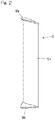
- FIG. 6 is a right side view of the blade
- FIG. 7 is a left side view of the blade
- FIG. 8 is a plan view of the blade as seen from above in FIG. 4 ;
- FIG. 9 is a sectional view of the blade along line IX-IX of FIG. 4 ;
- FIG. 10 is a bottom view of the blade as seen from below in FIG. 4 ;
- FIG. 11 is an illustration of dimensions of a blade-tip inclined part, which corresponds to an enlarged view of part XI of FIG. 6 ;
- FIG. 12 illustrates a variant of the blade in the same manner as FIG. 11 ;
- FIG. 13 illustrates an example of an attachment structure for the blade-tip inclined part of FIG. 11 ;
- FIG. 14 illustrates the example of the attachment structure for blade-tip inclined part of FIG. 12 ;
- FIG. 15 is a perspective view of a lighting facility with a power generation function according to a second embodiment of the present invention.
- FIG. 1 shows the wind power generating device 1 including a vertical axis wind turbine 2 and a generator 3 .
- the vertical axis wind turbine 2 includes a plurality of (two in the illustrated example) vertical blades 5 attached to a rotation shaft 3 a of the generator 3 through arms 6 a, 6 b.
- the plurality of blades 5 and the arms 6 a, 6 b constitute rotary blades 5 A.
- a support column 4 includes a cylindrical large-diameter part 4 a located on a lower side and a cylindrical small-diameter part 4 b located on an upper side, and the generator 3 is mounted at an upper end portion protruding from an upper end of the small-diameter part 4 b.
- the arms 6 a, 6 b include a main arm 6 a arranged horizontally and centrally and upper and lower subsidiary arms 6 b extending obliquely upward and obliquely downward from the main arm 6 a or the generator 3 and having tip ends connected to the blades 5 .
- the generator 3 may be a permanent magnet synchronous generator or the like, which includes a rotor (not illustrated) supported at an upper end of the support column 4 .
- each blade 5 includes a blade main part 5 a extending in a vertical direction and a pair of blade-tip inclined parts 5 b, 5 b extending from upper and lower ends of the blade main part 5 a toward the rotation shaft 3 a.
- the blade-tip inclined parts 5 b have a smaller thickness than that of the blade main part 5 a.
- the upper and lower blade-tip inclined parts 5 b, 5 b are shaped in a vertically symmetrical manner in the illustrated example.
- the blade main part 5 a has a constant cross-sectional shape over an entire length thereof.
- the blade main part 5 a has a lift type cross-sectional shape in this embodiment, as illustrated in FIG. 9 , which shows a cross section along line IX-IX of FIG. 4 .
- the blade main part has substantially a fish shape which is bulged on a front edge side in a rotation direction (the direction of the arrow) with respect to a center in a widthwise direction of the blade main part and has a gradually decreasing thickness toward a rear edge side.
- the blades 5 has a fixed rotation direction.
- the blades 5 are disposed in a direction in which the widthwise direction has a small angle of attack with respect to a tangential line of a blade rotation path a about a rotation axis of the generator 3 .
- the left side view shows a line b ( FIG. 7 ) representing a blade outer surface, a front edge c of the blade main part 5 , and a line d of the blade main part 5 on a rotation center side (inner side), as seen from a tangential direction of the blade rotation path a in FIG. 9 .
- the cross-sectional shape of the blade main part 5 a may have a drag type shape such as a flat plate-like shape.
- each blade-tip inclined part 5 b has a thickness t that is sufficiently smaller than a thickness L of the blade main part 5 a.
- the blade-tip inclined part 5 b has a flat plate shape having a constant thickness over its entirety.
- a ratio of the thickness t of the blade-tip inclined part 5 b to the thickness L of the blade main part 5 a may be, for example, 1/10 or smaller.
- a bent angle of the blade-tip inclined part 5 b relative to the blade main part 5 a may be, for example, from 30° to 80°.
- a length of each blade-tip inclined part 5 b may be, for example, from about 5 to 30% of an entire length of the blade main part 5 a.
- the blade-tip inclined part 5 b has a planar shape which protrudes most significantly at a position in the widthwise direction where the blade main part 5 a has a largest thickness and protrudes less and less toward a front end and a rear end of the blade-tip inclined part.
- the blade-tip inclined part 5 b may have a shape having a gradually decreasing thickness from the base end to the tip end as shown in FIG. 12 , instead of having a constant thickness over its entirety. Even in this case, the base end of the blade-tip inclined part 5 b has a sufficiently smaller thickness t′ than the thickness L of the blade main part 5 a.
- the tip end of the blade main part 5 a is provided with a connection part 5 c having a triangular cross-sectional shape, and a base end 5 bb of the blade-tip inclined part 5 b is connected to a side 5 ca of the cross section of the connection part 5 c.
- the material of the blades 5 may be a resin material such as a fiber reinforced plastic or a metal material such as a steel plate or an aluminum material. Alternatively, the blades may be made of multiple materials.
- the blade main part 5 a may be solid or hollow. Where the blade main part is hollow, for example, the blade main part is constructed by a frame (not illustrated) including ribs having a cross-sectional shape of the blade and arranged at plurality of positions in a blade lengthwise direction and a plurality of girder members extending in the blade lengthwise direction, and surface plates (not illustrated) attached to the frame so as to constitute front and rear sides of the blade.
- the blade-tip inclined part 5 b may be integrally formed with the blade main part 5 a or be produced as a separate member from the blade main part 5 a and attached to the blade main part 5 a. Where the blade-tip inclined part 5 b is produced as a separate component from the blade main part 5 a, for example, as shown in FIG. 13 , a blade-tip inclined part constituting member 5 b A including the blade-tip inclined part 5 b and an attachment part 5 d may be attached to the blade main part 5 a with a fixing tool 21 such as a bolt or an adhesive.
- FIG. 14 shows an example in which, where the blade-tip inclined part 5 b is shaped so as to have a gradually decreasing thickness from its base end to its tip end as in the example of FIG. 12 , the blade-tip inclined part 5 b is produced as a separate member from the blade main part 5 a and is attached to the blade main part 5 a at a joining surface 22 that is a base end surface of the blade-tip inclined part 5 b, with an adhesive or a fixing tool such as a bolt and a nut (not illustrated).
- each blade 5 includes the blade-tip inclined parts 5 b extending from upper and lower ends of the blade main part 5 a toward the rotation shaft 3 a, so that this configuration can provide the effects of suppressing a decrease in rotation efficiency of the blade due to generation of a wingtip vortex, increasing a total blade area so as to increase lift of the blade 5 , suppressing vertical flow of wind from the blade 5 so as to increase a rotation force, and improving starting characteristic, as in a vertical axis wind turbine having a conventional and thick blade-tip inclined part.
- the blade-tip inclined part 5 b has a smaller thickness than that of the blade main part 5 a, it has a reduced weight compared with a conventional and thick blade-tip inclined part, so that startability upon receiving light wind is improved, and the manufacture is simplified.
- the blade-tip inclined part 5 b has a constant thickness from a base end to a tip end of the blade-tip inclined part as shown in FIG. 11 and FIG. 13
- the blade-tip inclined part 5 b can be formed from a plate material so that the manufacture is further simplified.
- the blade-tip inclined part 5 b has a gradually decreasing thickness from the base end to the tip end as shown in the example of FIG. 12 and FIG. 14 , the blade-tip inclined part 5 b has excellent strength because the blade-tip inclined part has a greater thickness toward the base end side where a stronger load is applied due to a wind force.
- the blade-tip inclined part 5 b is made of a steel plate or a resin material
- the blade-tip inclined part 5 b can be produced further more easily.
- the blade-tip inclined part 5 b can be produced as a separate component from the blade main part 5 a as in the example of FIG. 13 and FIG. 14 and be attached to the blade main part 5 a, so that the manufacture can be further simplified.
- the blade main part 5 a has a substantially constant cross-sectional shape over the entire length thereof, the blade main part 5 a can be more easily manufactured thanks to its simple structure.
- the blade main part 5 a of a lift type with the blade-tip inclined part 5 b having a smaller thickness than that of the blade main part 5 a, the blade-tip inclined part 5 b can effectively exhibit the above-described effects.
- FIG. 15 shows a lighting facility with a power generation function according to a second embodiment of the present invention, the lighting facility including a wind power generating device 1 .
- the lighting facility with a power generation function in FIG. 15 is configured as a lighting facility to be installed as a street light or a lamppost on a street or in a park, and the lighting facility includes a support column 4 , a vertical axis wind turbine 2 of the wind power generating device 1 disposed on top of the support column, a photovoltaic panel 11 , a lighting fitting 12 , and a plurality of secondary batteries 13 inside a large-diameter part 4 a of the support column 4 .
- the photovoltaic panel 11 is attached to a small-diameter part 4 b of the support column 4
- the lighting fitting 12 is attached to the small-diameter part 4 b of the support column 4 at a position below the photovoltaic panel 11 .
- the lighting fitting 12 may include a light source such as an LED, which may run on direct current or alternating current to be lighted.
- the wind power generating device 1 is configured in the same manner as the wind power generating device 1 according to the first embodiment shown in FIG. 1 to FIG. 11 and is provided with blade-tip inclined parts 5 b at upper and lower ends of the blades 5 .
- the lighting facility stores the electricity generated by the wind power generating device 1 and the photovoltaic panel 11 in the secondary batteries 13 and uses the stored electricity to turn on the lighting fitting 12 at night and the like. Since the wind power generating device 1 has high rotation efficiency because the blades 5 are provided with the blade-tip inclined parts 5 b as described above, the wind power generating device has an advantage that it has high power generation capability even at low wind speeds. In addition, the photovoltaic panel 11 and the wind power generating device 1 generate electricity in the daytime.
- each blade-tip inclined part 5 b forms a bend and extends linearly from the blade main part 5 a
- the blade-tip inclined part 5 b may have a curved cross section along a protrusion direction of the blade-tip inclined part.
Landscapes
- Engineering & Computer Science (AREA)
- General Engineering & Computer Science (AREA)
- Life Sciences & Earth Sciences (AREA)
- Sustainable Development (AREA)
- Sustainable Energy (AREA)
- Chemical & Material Sciences (AREA)
- Combustion & Propulsion (AREA)
- Mechanical Engineering (AREA)
- Power Engineering (AREA)
- Physics & Mathematics (AREA)
- Fluid Mechanics (AREA)
- Wind Motors (AREA)
Abstract
Description
-
- a vertical rotation shaft; and
- a plurality of vertical blades arranged around the rotation shaft and attached to the rotation shaft through an arm, wherein
- each of the blades includes a blade main part and a pair of blade-tip inclined parts extending from upper and lower ends of the blade main part toward the rotation shaft, and
- each of the blade-tip inclined parts has a smaller thickness than a thickness of the blade main part.
-
- the vertical axis wind turbine according to any of the above configurations of the present invention; and
- a generator configured to generate electricity from rotation of the vertical axis wind turbine transmitted to the generator.
-
- the wind power generating device of the present invention;
- a photovoltaic panel;
- a secondary battery configured to store electricity generated by the wind power generating device and the photovoltaic panel; and
- a lighting fitting configured to light up using the electricity stored in the secondary battery; and
- a support column supporting the wind power generating device, the photovoltaic panel, the secondary battery, and the lighting fitting.
- 1 . . . Wind power generating device
- 2 . . . Vertical axis wind turbine
- 3 . . . Generator
- 3 a . . . Rotation shaft
- 4 . . . Support column
- 5 . . . Blade
- 5 a . . . Blade main part
- 5 b . . . Blade-tip inclined part
- 6 a, 6 b . . . Arm
- 11 . . . Photovoltaic panel
- 12 . . . Lighting fitting
- 13 . . . Secondary battery
Claims (6)
Applications Claiming Priority (4)
| Application Number | Priority Date | Filing Date | Title |
|---|---|---|---|
| JP2018-101989 | 2018-05-29 | ||
| JP2018101989A JP6997676B2 (en) | 2018-05-29 | 2018-05-29 | Vertical axis wind turbine and wind power generation equipment and lighting equipment equipped with it |
| JPJP2018-101989 | 2018-05-29 | ||
| PCT/JP2019/020919 WO2019230655A1 (en) | 2018-05-29 | 2019-05-27 | Vertical axis windmill, and wind power generating device and lighting facility comprising same |
Related Parent Applications (1)
| Application Number | Title | Priority Date | Filing Date |
|---|---|---|---|
| PCT/JP2019/020919 Continuation WO2019230655A1 (en) | 2018-05-29 | 2019-05-27 | Vertical axis windmill, and wind power generating device and lighting facility comprising same |
Publications (2)
| Publication Number | Publication Date |
|---|---|
| US20210095637A1 US20210095637A1 (en) | 2021-04-01 |
| US11614070B2 true US11614070B2 (en) | 2023-03-28 |
Family
ID=68698175
Family Applications (1)
| Application Number | Title | Priority Date | Filing Date |
|---|---|---|---|
| US17/102,896 Active US11614070B2 (en) | 2018-05-29 | 2020-11-24 | Vertical axis wind turbine, and wind power generating device and lighting facility comprising same |
Country Status (6)
| Country | Link |
|---|---|
| US (1) | US11614070B2 (en) |
| EP (1) | EP3805554B1 (en) |
| JP (1) | JP6997676B2 (en) |
| KR (1) | KR102635374B1 (en) |
| CN (1) | CN112243475A (en) |
| WO (1) | WO2019230655A1 (en) |
Families Citing this family (5)
| Publication number | Priority date | Publication date | Assignee | Title |
|---|---|---|---|---|
| JP6449509B1 (en) | 2018-06-08 | 2019-01-09 | 株式会社グローバルエナジー | Vertical axis wind turbine, its vertically long blade and wind power generator |
| JP7573374B2 (en) * | 2020-03-27 | 2024-10-25 | Ntn株式会社 | Vertical Axis Wind Turbine |
| FI130754B1 (en) * | 2021-11-02 | 2024-02-27 | Single Wing Energy Oy | Rotor blade and wind turbine |
| KR102515431B1 (en) * | 2022-04-18 | 2023-03-30 | 알머티리얼즈 주식회사 | Thermoelectric-Windpower Combined Power Generation System |
| US12448945B2 (en) * | 2023-08-08 | 2025-10-21 | Hamid R. Rahai | Optimized end plates for vertical axis wind turbine |
Citations (13)
| Publication number | Priority date | Publication date | Assignee | Title |
|---|---|---|---|---|
| JP2004204801A (en) | 2002-12-26 | 2004-07-22 | Fjc:Kk | Wind receiving blade for windmill |
| JP2005061328A (en) | 2003-08-13 | 2005-03-10 | Fjc:Kk | Blade of windmill and vertical axis windmill |
| JP2006118384A (en) | 2004-10-20 | 2006-05-11 | Fjc:Kk | Vertical-shaft windmill |
| US20060120872A1 (en) | 2003-06-09 | 2006-06-08 | Shinko Electric Co., Ltd | Vertical shaft-type wind power generation device and method of producing blade structure and method of installing blade wheel for wind power generation device, and wind power generation plant for wind protection |
| US20060145668A1 (en) | 2003-06-09 | 2006-07-06 | Shinko Electric Co., Ltd | Generator and power supply for use therein |
| US20070071604A1 (en) | 2003-10-22 | 2007-03-29 | Masahiko Suzuki | Vertical axis windmill |
| JP2010116921A (en) | 2003-06-09 | 2010-05-27 | Sinfonia Technology Co Ltd | Vertical axis wind turbine generator |
| CN102748207A (en) | 2012-08-13 | 2012-10-24 | 赵立华 | blades and impeller of vertical-shaft wind power generator |
| WO2013024515A1 (en) | 2011-08-12 | 2013-02-21 | 大島工業株式会社 | Hybrid generation-type streetlamp |
| JP2016075241A (en) | 2014-10-08 | 2016-05-12 | アロイ工業株式会社 | Wind power generator and power supply device |
| JP5969651B1 (en) | 2015-04-21 | 2016-08-17 | 紳一郎 中島 | Windmill wing |
| WO2016148016A1 (en) | 2015-03-16 | 2016-09-22 | Ntn株式会社 | Impeller and natural energy power generation device provided with same |
| WO2017179607A1 (en) | 2016-04-15 | 2017-10-19 | Ntn株式会社 | Hybrid street light |
Family Cites Families (5)
| Publication number | Priority date | Publication date | Assignee | Title |
|---|---|---|---|---|
| JP2009191744A (en) * | 2008-02-14 | 2009-08-27 | Yamaguchi Prefecture | Vertical axis windmill |
| JP2010116971A (en) * | 2008-11-12 | 2010-05-27 | Yazaki Corp | Fixing clip |
| JP2011169267A (en) * | 2010-02-19 | 2011-09-01 | Global Energy Co Ltd | Vertical axis wind turbine |
| KR102456995B1 (en) * | 2015-03-16 | 2022-10-19 | 엔티엔 가부시키가이샤 | An impeller and a natural energy power generation device having the same |
| CN105202454A (en) * | 2015-10-09 | 2015-12-30 | 唐山市拓又达科技有限公司 | Vertical-axis wind-solar hybrid lighting equipment |
-
2018
- 2018-05-29 JP JP2018101989A patent/JP6997676B2/en active Active
-
2019
- 2019-05-27 KR KR1020207036333A patent/KR102635374B1/en active Active
- 2019-05-27 CN CN201980035825.8A patent/CN112243475A/en active Pending
- 2019-05-27 WO PCT/JP2019/020919 patent/WO2019230655A1/en not_active Ceased
- 2019-05-27 EP EP19810182.6A patent/EP3805554B1/en active Active
-
2020
- 2020-11-24 US US17/102,896 patent/US11614070B2/en active Active
Patent Citations (18)
| Publication number | Priority date | Publication date | Assignee | Title |
|---|---|---|---|---|
| JP2004204801A (en) | 2002-12-26 | 2004-07-22 | Fjc:Kk | Wind receiving blade for windmill |
| US7510366B2 (en) | 2003-06-09 | 2009-03-31 | Shinko Electric Co., Ltd. | Vertical axis type wind power station |
| JP2010116921A (en) | 2003-06-09 | 2010-05-27 | Sinfonia Technology Co Ltd | Vertical axis wind turbine generator |
| US20060120872A1 (en) | 2003-06-09 | 2006-06-08 | Shinko Electric Co., Ltd | Vertical shaft-type wind power generation device and method of producing blade structure and method of installing blade wheel for wind power generation device, and wind power generation plant for wind protection |
| US20060145668A1 (en) | 2003-06-09 | 2006-07-06 | Shinko Electric Co., Ltd | Generator and power supply for use therein |
| US7432608B2 (en) | 2003-06-09 | 2008-10-07 | Shinko Electric Co., Ltd. | Generator and power supply for use therein |
| JP2005061328A (en) | 2003-08-13 | 2005-03-10 | Fjc:Kk | Blade of windmill and vertical axis windmill |
| US20070071604A1 (en) | 2003-10-22 | 2007-03-29 | Masahiko Suzuki | Vertical axis windmill |
| US7360995B2 (en) | 2003-10-22 | 2008-04-22 | Global Energy Co., Ltd. | Vertical axis windmill |
| JP2006118384A (en) | 2004-10-20 | 2006-05-11 | Fjc:Kk | Vertical-shaft windmill |
| WO2013024515A1 (en) | 2011-08-12 | 2013-02-21 | 大島工業株式会社 | Hybrid generation-type streetlamp |
| CN102748207A (en) | 2012-08-13 | 2012-10-24 | 赵立华 | blades and impeller of vertical-shaft wind power generator |
| JP2016075241A (en) | 2014-10-08 | 2016-05-12 | アロイ工業株式会社 | Wind power generator and power supply device |
| WO2016148016A1 (en) | 2015-03-16 | 2016-09-22 | Ntn株式会社 | Impeller and natural energy power generation device provided with same |
| JP5969651B1 (en) | 2015-04-21 | 2016-08-17 | 紳一郎 中島 | Windmill wing |
| JP2016205204A (en) | 2015-04-21 | 2016-12-08 | 中島 紳一郎 | Wind turbine blade |
| WO2017179607A1 (en) | 2016-04-15 | 2017-10-19 | Ntn株式会社 | Hybrid street light |
| US20190041015A1 (en) | 2016-04-15 | 2019-02-07 | Ntn Corporation | Hybrid street light |
Non-Patent Citations (5)
| Title |
|---|
| Extended European Search Report dated Jan. 31, 2022 in European Patent Application No. 19810182.6. |
| First Examination Report dated Jul. 8, 2022 in Indian Patent Application No. 202017051128. |
| International Preliminary Report on Patentability dated Dec. 10, 2020 with Written Opinion of the International Searching Authority issued in International Patent Application No. PCT/JP2019/020919. |
| International Search Report dated Jul. 23, 2019 in International Patent Application No. PCT/JP2019/020919. |
| Notice of Reasons for Refusal dated Sep. 7, 2021, in Japanese Application No. 2018-101989 (8 pages including translation). |
Also Published As
| Publication number | Publication date |
|---|---|
| KR20210015857A (en) | 2021-02-10 |
| EP3805554B1 (en) | 2023-12-20 |
| EP3805554A1 (en) | 2021-04-14 |
| WO2019230655A8 (en) | 2020-12-10 |
| CN112243475A (en) | 2021-01-19 |
| KR102635374B1 (en) | 2024-02-13 |
| JP6997676B2 (en) | 2022-01-17 |
| JP2019206925A (en) | 2019-12-05 |
| US20210095637A1 (en) | 2021-04-01 |
| EP3805554A4 (en) | 2022-03-02 |
| WO2019230655A1 (en) | 2019-12-05 |
Similar Documents
| Publication | Publication Date | Title |
|---|---|---|
| US11614070B2 (en) | Vertical axis wind turbine, and wind power generating device and lighting facility comprising same | |
| CN100347440C (en) | Windmill for wind power generation | |
| EP3085952B1 (en) | Airflow configuration for a wind turbine rotor blade | |
| US4408958A (en) | Wind turbine blade | |
| US9523279B2 (en) | Rotor blade fence for a wind turbine | |
| AU2005261490B2 (en) | Modular construction for wind turbine blade | |
| US20110042962A1 (en) | Vertical shaft type darius windmill | |
| US20130094970A1 (en) | Wind turbine blade, wind turbine generator equipped with wind turbine blade and method of designing wind turbine blade | |
| US20110142677A1 (en) | Winglet for wind turbine rotor blade | |
| US8105034B2 (en) | Vertical-axis wind turbine and method for the production thereof | |
| KR101197322B1 (en) | Wind power generation using drive wind force of car | |
| EP3655645A1 (en) | Airflow configuration for a wind turbine rotor blade | |
| JP2015078667A (en) | Wind turbine blade and wind power generator | |
| EP2535563A1 (en) | High-efficiency high-power vertical axis wind generator | |
| JP2007205359A (en) | Thin wing | |
| EP2657514A1 (en) | Vertical-axis wind or hydraulic turbine structure | |
| JP2006029226A (en) | Wind power generation device and lighting system | |
| CN106120585A (en) | A kind of silencing energy economizer type bridge paravent | |
| US7854595B2 (en) | Wind turbine blade tip shapes | |
| JP3991103B2 (en) | Seven arc thin wing | |
| WO2020219001A1 (en) | Vertical axis-type wind turbine assembly | |
| WO2012073124A1 (en) | System for generating electrical energy from low speed wind energy by means of two systems of drive blades | |
| US20120269641A1 (en) | Wind Turbine Rotor Blades Sharing Blade Roots for Advantageous Blades and Hubs | |
| RU2174190C1 (en) | Rotor of wind-electric generating plant | |
| RU2852803C1 (en) | Spherical wind turbine |
Legal Events
| Date | Code | Title | Description |
|---|---|---|---|
| FEPP | Fee payment procedure |
Free format text: ENTITY STATUS SET TO UNDISCOUNTED (ORIGINAL EVENT CODE: BIG.); ENTITY STATUS OF PATENT OWNER: LARGE ENTITY |
|
| STPP | Information on status: patent application and granting procedure in general |
Free format text: DOCKETED NEW CASE - READY FOR EXAMINATION |
|
| AS | Assignment |
Owner name: NTN CORPORATION, JAPAN Free format text: ASSIGNMENT OF ASSIGNORS INTEREST;ASSIGNORS:ITO, TAKERU;HAYASHI, TATSUYA;KAWASE, TATSUO;SIGNING DATES FROM 20210330 TO 20210415;REEL/FRAME:056549/0529 |
|
| STPP | Information on status: patent application and granting procedure in general |
Free format text: NON FINAL ACTION MAILED |
|
| STPP | Information on status: patent application and granting procedure in general |
Free format text: RESPONSE TO NON-FINAL OFFICE ACTION ENTERED AND FORWARDED TO EXAMINER |
|
| STPP | Information on status: patent application and granting procedure in general |
Free format text: FINAL REJECTION MAILED |
|
| STPP | Information on status: patent application and granting procedure in general |
Free format text: ADVISORY ACTION MAILED |
|
| STPP | Information on status: patent application and granting procedure in general |
Free format text: DOCKETED NEW CASE - READY FOR EXAMINATION |
|
| STPP | Information on status: patent application and granting procedure in general |
Free format text: NON FINAL ACTION MAILED |
|
| STPP | Information on status: patent application and granting procedure in general |
Free format text: FINAL REJECTION MAILED |
|
| STPP | Information on status: patent application and granting procedure in general |
Free format text: ADVISORY ACTION MAILED |
|
| STPP | Information on status: patent application and granting procedure in general |
Free format text: DOCKETED NEW CASE - READY FOR EXAMINATION |
|
| STPP | Information on status: patent application and granting procedure in general |
Free format text: NOTICE OF ALLOWANCE MAILED -- APPLICATION RECEIVED IN OFFICE OF PUBLICATIONS |
|
| STCF | Information on status: patent grant |
Free format text: PATENTED CASE |