US11584159B2 - Vehicle wheel and Helmholtz resonator - Google Patents

Vehicle wheel and Helmholtz resonator Download PDF

Info

Publication number
US11584159B2
US11584159B2 US16/367,969 US201916367969A US11584159B2 US 11584159 B2 US11584159 B2 US 11584159B2 US 201916367969 A US201916367969 A US 201916367969A US 11584159 B2 US11584159 B2 US 11584159B2
Authority
US
United States
Prior art keywords
helmholtz resonator
wheel
adhesive material
sub
air chamber
Prior art date
Legal status (The legal status is an assumption and is not a legal conclusion. Google has not performed a legal analysis and makes no representation as to the accuracy of the status listed.)
Active, expires
Application number
US16/367,969
Other versions
US20190299708A1 (en
Inventor
Masaaki Nishi
Youichi Kamiyama
Toshinobu Saito
Toshimitsu Maki
Current Assignee (The listed assignees may be inaccurate. Google has not performed a legal analysis and makes no representation or warranty as to the accuracy of the list.)
Honda Motor Co Ltd
Original Assignee
Honda Motor Co Ltd
Priority date (The priority date is an assumption and is not a legal conclusion. Google has not performed a legal analysis and makes no representation as to the accuracy of the date listed.)
Filing date
Publication date
Application filed by Honda Motor Co Ltd filed Critical Honda Motor Co Ltd
Assigned to HONDA MOTOR CO., LTD. reassignment HONDA MOTOR CO., LTD. ASSIGNMENT OF ASSIGNORS INTEREST (SEE DOCUMENT FOR DETAILS). Assignors: KAMIYAMA, YOUICHI, MAKI, TOSHIMITSU, NISHI, MASAAKI, SAITO, Toshinobu
Publication of US20190299708A1 publication Critical patent/US20190299708A1/en
Application granted granted Critical
Publication of US11584159B2 publication Critical patent/US11584159B2/en
Active legal-status Critical Current
Adjusted expiration legal-status Critical

Links

Images

Classifications

    • BPERFORMING OPERATIONS; TRANSPORTING
    • B60VEHICLES IN GENERAL
    • B60BVEHICLE WHEELS; CASTORS; AXLES FOR WHEELS OR CASTORS; INCREASING WHEEL ADHESION
    • B60B21/00Rims
    • B60B21/02Rims characterised by transverse section
    • BPERFORMING OPERATIONS; TRANSPORTING
    • B60VEHICLES IN GENERAL
    • B60BVEHICLE WHEELS; CASTORS; AXLES FOR WHEELS OR CASTORS; INCREASING WHEEL ADHESION
    • B60B21/00Rims
    • B60B21/12Appurtenances, e.g. lining bands
    • BPERFORMING OPERATIONS; TRANSPORTING
    • B60VEHICLES IN GENERAL
    • B60RVEHICLES, VEHICLE FITTINGS, OR VEHICLE PARTS, NOT OTHERWISE PROVIDED FOR
    • B60R13/00Elements for body-finishing, identifying, or decorating; Arrangements or adaptations for advertising purposes
    • B60R13/08Insulating elements, e.g. for sound insulation
    • B60R13/0884Insulating elements, e.g. for sound insulation for mounting around noise sources, e.g. air blowers
    • GPHYSICS
    • G10MUSICAL INSTRUMENTS; ACOUSTICS
    • G10KSOUND-PRODUCING DEVICES; METHODS OR DEVICES FOR PROTECTING AGAINST, OR FOR DAMPING, NOISE OR OTHER ACOUSTIC WAVES IN GENERAL; ACOUSTICS NOT OTHERWISE PROVIDED FOR
    • G10K11/00Methods or devices for transmitting, conducting or directing sound in general; Methods or devices for protecting against, or for damping, noise or other acoustic waves in general
    • G10K11/16Methods or devices for protecting against, or for damping, noise or other acoustic waves in general
    • G10K11/172Methods or devices for protecting against, or for damping, noise or other acoustic waves in general using resonance effects
    • BPERFORMING OPERATIONS; TRANSPORTING
    • B60VEHICLES IN GENERAL
    • B60BVEHICLE WHEELS; CASTORS; AXLES FOR WHEELS OR CASTORS; INCREASING WHEEL ADHESION
    • B60B2310/00Manufacturing methods
    • B60B2310/30Manufacturing methods joining
    • B60B2310/318Manufacturing methods joining by adhesive bonding, e.g. glueing
    • BPERFORMING OPERATIONS; TRANSPORTING
    • B60VEHICLES IN GENERAL
    • B60BVEHICLE WHEELS; CASTORS; AXLES FOR WHEELS OR CASTORS; INCREASING WHEEL ADHESION
    • B60B2900/00Purpose of invention
    • B60B2900/10Reduction of
    • B60B2900/133Noise

Definitions

  • the present invention relates to a vehicle wheel.
  • the Helmholtz resonator allows the both edges thereof to be elastically deformed when pressed against the outer circumferential surface of the well part, thereby being easily fitted into the circumferential groove of the rim. Consequently, the Helmholtz resonator can be easily mounted on the wheel.
  • the conventional wheel with the Helmholtz resonator (for example, see Patent document 1) requires cutting and forming the circumferential groove for mounting the resonator on the rim. For this reason, the wheel has posed a problem in that a manufacturing process thereof becomes complicated to increase a manufacturing cost.
  • a resonator mounting structure in which the Helmholtz resonator is fixed to the outer circumferential surface of the well part with an adhesive material.
  • the present invention has therefore been made in view of the above problems, and an object of the invention is to provide a vehicle wheel capable of further improving fixing strength of a Helmholtz resonator mounted on a rim with an adhesive material.
  • a vehicle wheel reflecting one aspect of the present invention includes a Helmholtz resonator mounted thereon with an adhesive material, wherein a thickness of the adhesive material on a part of the Helmholtz resonator on which centrifugal force acts strongly during rotation of the wheel is set to be thicker than a thickness of the adhesive material on other parts of the Helmholtz resonator.
  • the vehicle wheel reflecting one aspect of the present invention thus makes it possible to further improve fixing strength of the Helmholtz resonator mounted on the rim with an adhesive material.
  • FIG. 1 is a perspective view of a vehicle wheel according to an embodiment of the present invention.
  • FIG. 2 is an overall perspective view of a sub-air chamber member.
  • FIG. 3 is a sectional view taken along the line in FIG. 1 .
  • FIG. 4 is a partially omitted and enlarged longitudinal sectional view taken along the IV-IV line in FIG. 3 .
  • FIG. 5 is a partially enlarged sectional view of the part V indicated by an arrow in FIG. 3 .
  • FIG. 6 is a partially enlarged sectional view of the part VI indicated by an arrow in FIG. 4 .
  • FIG. 7 is a partially enlarged sectional view of the periphery of a lower part of a bridge in a vehicle wheel according to a first modification.
  • FIG. 8 is a partially enlarged sectional view of the periphery of a lower part of a bridge in a vehicle wheel according to a second modification.
  • FIGS. 9 A, 9 B and 9 C are partial plan views of a Helmholtz resonator showing modifications of an end part of the Helmholtz resonator in a wheel circumferential direction.
  • a sub-air chamber member serving as a Helmholtz resonator and of a mounting structure of the sub-air chamber member on a rim by an adhesive material.
  • reference sign “X” denotes a wheel circumferential direction
  • reference sign “Y” denotes a wheel width direction
  • reference sign “Z” denotes a wheel radial direction.
  • an inner side is defined as “one side” and an outer side is defined as “other side”.
  • FIG. 1 is a perspective view of a vehicle wheel 1 according to an embodiment of the present invention.
  • the vehicle wheel 1 is configured to allow an sub-air chamber member 10 (Helmholtz resonator) made of a synthetic resin such as polyamide resin to be mounted on a rim 11 made of metal such as aluminum alloy and magnesium alloy.
  • an sub-air chamber member 10 Helmholtz resonator
  • a synthetic resin such as polyamide resin
  • the vehicle wheel 1 is provided with a stopper 41 as described in detail later.
  • reference sign 12 denotes a disk 12 for connecting the rim 11 to a hub (not shown).
  • the rim 11 includes a well part 11 c which is recessed inward (toward a rotation center) in the wheel radial direction between bead seats (not shown) formed on both end parts of the rim 11 in the wheel width direction Y.
  • An outer circumferential surface 11 d of the well part 11 c is defined by a bottom face of the concave part and has substantially the same diameter on the wheel shaft throughout the wheel width direction Y.
  • the rim 11 in the present embodiment is provided with a vertical wall 15 a and a vertical wall 15 b .
  • the vertical walls 15 a , 15 b rise from the outer circumferential surface 11 d outward in the wheel radial direction with a predetermined distance between each other in the wheel width direction Y.
  • the rim 11 in the present embodiment is not limited to this configuration, but may adopt configuration not having the vertical walls 15 a , 15 b as described later.
  • the vertical wall 15 a formed at the one side (inner side) in the wheel width direction Y is formed in a rising part 17 that erects from the outer circumferential surface 11 d of the well part 11 c toward a rim flange side.
  • the vertical wall 15 b is configured by a circumferential wall 19 that extends in the wheel circumferential direction X at the middle in the wheel width direction Y of the outer circumferential surface 11 d .
  • the vertical walls 15 a , 15 b are each simply referred to as a vertical wall 15 where they are not particularly distinguished from each other.
  • the vertical walls 15 a , 15 b annularly extend in the wheel circumferential direction X with a predetermined distance between each other, thereby forming side faces 14 (see FIG. 3 ) that face each other as described later.
  • the side faces 14 are formed so that an angle between each of the side faces 14 and the outer circumferential surface 11 d (see FIG. 3 ) is substantially a right angle.
  • FIG. 2 is an overall perspective view of the sub-air chamber member 10 .
  • FIG. 3 is a sectional view taken along the III-III line in FIG. 1 .
  • FIG. 4 is a partially omitted and enlarged longitudinal sectional view taken along the IV-IV line in FIG. 3 .
  • the sub-air chamber member 10 is a member elongated in the wheel circumferential direction X and includes a main body 13 , a tubular body 18 and a plate-like extension part 8 .
  • the sub-air chamber member 10 is configured to have a symmetric shape in the wheel circumferential direction X with respect to a partition wall 16 that extends in the wheel width direction Y at the center of the main body 13 .
  • the main body 13 is curved in a longitudinal direction thereof. In other words, the main body 13 is configured to follow the wheel circumferential direction X when the sub-air chamber member 10 is mounted on the outer circumferential surface 11 d (see FIG. 1 ) of the well part 11 c (see FIG. 1 ).
  • the main body 13 has a hollow part inside.
  • the hollow part (not shown) forms a sub-air chamber SC (see FIG. 3 ) as described later.
  • the hollow part is divided by the partition wall 16 into two parts in the wheel circumferential direction X.
  • the main body 13 has a nearly rectangular shape elongated in the wheel width direction Y in cross section orthogonal to the longitudinal direction (the wheel circumferential direction X in FIG. 2 ).
  • the main body 13 has configuration in which a bottom part 25 b (bottom plate) that is disposed along the outer circumferential surface 11 d of the well part 11 c , side parts 25 c (side plates) that are disposed along the side faces 14 of the pair of vertical walls 15 , and an upper part 25 a (upper plate) that is disposed to face the bottom part 25 b , are mutually connected so as to form a nearly rectangular shape.
  • the upper part 25 a , the bottom part 25 b and the side parts 25 c are formed to surround the sub-air chamber SC inside the main body 13 .
  • a height of the main body 13 from the outer circumferential surface 11 d is the same as a height of the vertical wall 15 .
  • a width of the main body 13 is set to a length at which the main body 13 is fitted between the vertical wall 15 a and the vertical wall 15 b.
  • the width of the main body 13 may be set to be longer than a distance between the vertical walls 15 a , 15 b to such an extent that the main body 13 receives reaction force from the vertical walls 15 a , 15 b .
  • the width of the main body 13 is preferably set so as not to allow volume of the sub-air chamber SC after the press-fitting to depart from designed volume.
  • the main body 13 has a plurality of (in this embodiment, ten) bridges 33 formed to be arranged at equal intervals in the wheel circumferential direction X. Moreover, the bridges 33 are arranged in two rows in the wheel width direction Y.
  • the bridges 33 are each formed with an upper side connecting part 33 a and a lower side connecting part 33 b being joined together at a nearly central position between the upper part 25 a and the bottom part 25 b.
  • the upper side connecting part 33 a is formed so as to allow the upper part 25 a to be partially recessed toward the bottom part 25 b .
  • the lower side connecting part 33 b is formed so as to allow the bottom part 25 b to be partially recessed toward the upper part 25 a.
  • the upper side connecting part 33 a and the lower side connecting part 33 b are joined together via a joining part 33 c which is formed to be displaced to the outer circumferential surface 11 d side of the well part 11 c from the central part between the upper part 25 a and the bottom part 25 b.
  • the bridge 33 has a nearly cylindrical shape and partially connects the upper part 25 a with the bottom part 25 b . Moreover, the bridge 33 forms circular openings in planar view at corresponding positions in the up-down direction of the main body 13 .
  • the main body 13 has an inclined part 25 d at an end part thereof in the wheel circumferential direction X as shown in FIG. 2 .
  • the sub-air chamber SC is formed to allow volume thereof to be gradually reduced from the central part in the wheel circumferential direction X of the main body 13 toward an edge in the wheel circumferential direction X of the main body 13 , i.e., toward a leading end Le of the main body 13 .
  • the inclined part 25 d is formed by allowing the upper part 25 a of the main body 13 to be displaced so as to gradually come near the bottom part 25 b as the upper part 25 a extends toward the leading end Le of the main body 13 , and allowing the upper part 25 a and the bottom part 25 b to be connected together at the leading end Le.
  • the inclined part 25 d has an inclination angle ⁇ which is preferably less than 45 degrees and more preferably equal to or less than 30 degrees.
  • the inclination angle ⁇ in the present embodiment means an angle formed on a narrow-angle side between the inclined part 25 d and a perpendicular line L 2 that intersects at the connecting point P a line segment L 1 that connects the connecting point P with a rotation center (not shown) of the wheel.
  • tubular body 18 (see FIG. 1 ) will be described.
  • the tubular body 18 is formed at a position biased to the one side (the inner side of the vehicle wheel 1 ) in the wheel width direction Y on the main body 13 so as to protrude from the main body 13 in the wheel circumferential direction X.
  • the sub-air chamber member 10 in the present embodiment is formed, as described above, into a symmetric shape in the wheel circumferential direction X with respect to the partition wall 16 . Accordingly, although only one tubular body 18 is shown in FIG. 1 , the tubular bodies 18 in the present embodiment are disposed to form a pair at positions symmetrical to each other on both end parts in the longitudinal direction (the wheel circumferential direction X) of the main body 13 .
  • the tubular body 18 has a communication hole 18 a formed inside.
  • the communication hole 18 a allows the sub-air chamber SC (see FIG. 3 ) formed inside the main body 13 to be communicated with a tire air chamber 9 (see FIG. 3 ) which is to be formed between the well part 11 c (see FIG. 3 ) and a tire (not shown).
  • the plate-like extension part 8 extends from the leading end Le of the main body 13 in the wheel circumferential direction X.
  • the plate-like extension part 8 is composed of a plate-like body having a rectangular shape in planar view and formed with nearly the same width as the main body 13 in the wheel width direction Y.
  • the plate-like extension part 8 is curved in the wheel circumferential direction X. That is, the plate-like extension part 8 is configured to follow the wheel circumferential direction X with a predetermined gap when the sub-air chamber member 10 is mounted on the outer circumferential surface 11 d (see FIG. 1 ) of the well part 11 c (see FIG. 1 ).
  • the plate-like extension part 8 in the present embodiment extends in the wheel circumferential direction X so as to have a slightly longer radius of curvature than a radius of curvature in the wheel circumferential direction X of the bottom part 25 b , depending on film thicknesses T 1 , T 2 (see FIG. 6 ) of the adhesive material 21 as described later.
  • the sub-air chamber member 10 in the present embodiment is a blow molded product using a synthetic resin such as polyamide resin as described above.
  • a synthetic resin such as polyamide resin as described above.
  • the above synthetic resin is not specifically limited, but polyamide resin containing polyamide MXD6 (Registered trade mark) as a base resin, and nylon 6 are especially preferably used.
  • the sub-air chamber member 10 allows the bottom part 25 b of the main body 13 and the outer circumferential surface 11 d of the well part 11 c to be connected via the adhesive material 21 in the wheel width direction Y.
  • the sub-air chamber member 10 allows a lower surface of the plate-like extension part 8 and the outer circumferential surface 11 d of the well part 11 c to be connected via the adhesive material 21 , in addition to adhesion of the main body 13 to the outer circumferential surface 11 d , in the wheel circumferential direction X.
  • the adhesive material 21 examples include thermoplastic resin-based adhesive such as ethylene-vinyl acetate resin; thermosetting resin-based adhesive such as epoxy resin, polyurethane resin and polyamide resin; and elastomer-based adhesive such as synthetic rubber and thermoplastic elastomer, but the adhesive material is not limited to these examples.
  • the form of hardening of the adhesive material 21 is not specifically limited, but chemical reaction hardening is especially preferably used.
  • the adhesive material 21 can be coated on either the sub-air chamber member 10 or the rim 11 . Moreover, the adhesive material 21 can also be coated on both of the sub-air chamber member 10 and the rim 11 .
  • coating method for the adhesive material 21 examples include bar coating method, roll coating method, spray coating method, brush coating method, and hot-melt coating method, but the coating method is not limited to these examples.
  • the vehicle wheel 1 (see FIG. 1 ) according to the present embodiment allows a thickness of the adhesive material 21 (see FIG. 3 ) on a part of the sub-air chamber member 10 on which centrifugal force acts strongly during rotation of the wheel to be thicker than a thickness of the adhesive material 21 on other parts of the sub-air chamber member 10 .
  • F centrifugal force
  • the part on which the centrifugal force acts strongly is directed to a part on which the centrifugal force acts more strongly than the reference part, e.g., a part at which the bridge 33 shown in FIG. 3 is formed, a part at which the side part 25 c is formed, and the plate-like extension part 8 shown in FIG. 4 .
  • the vehicle wheel 1 includes a regular part 7 a (the bottom part 25 b as the reference part) of the sub-air chamber member 10 (Helmholtz resonator), and an adhesive strength increasing part 7 b that is a part (the formation part of the bridge 33 ) on which the centrifugal force acts more strongly than the regular part 7 a during rotation of the wheel, and on which the adhesive material 21 is coated more thickly than the regular part 7 a.
  • a regular part 7 a the bottom part 25 b as the reference part
  • the sub-air chamber member 10 Helmholtz resonator
  • FIG. 5 is a partially enlarged sectional view of the part V indicated by an arrow in FIG. 3 .
  • the adhesive strength increasing part 7 b is formed of an opposed surface of the main body 13 that faces the outer circumferential surface 11 d of the well part 11 c at a lower place of the bridge 33 .
  • the regular part 7 a is formed of part of an opposed surface of the bottom part 25 b that faces the outer circumferential surface 11 d of the well part 11 c , i.e., the opposed surface exclusive of the adhesive strength increasing part 7 b.
  • the bridge 33 is located unlike the regular part 7 a . That is, centrifugal force according to the amount of materials (e.g., mass of synthetic resin) forming the bridge 33 is generated in the adhesive strength increasing part 7 b . Consequently, as described above, the centrifugal force acts more strongly on the adhesive strength increasing part 7 b than on the regular part 7 a above which the bridge 33 is not located.
  • materials e.g., mass of synthetic resin
  • the adhesive material 21 is more thickly coated on the adhesive strength increasing part 7 b than on the regular part 7 a.
  • the joining part 33 c of the bridge 33 is formed to be displaced to the outer circumferential surface 11 d side of the well part 11 c from the central part between the upper part 25 a (see FIG. 3 ) and the bottom part 25 b (see FIG. 3 ).
  • the inside of a lower part of the bridge 33 thus formed i.e., the inside of the lower side connecting part 33 b can be filled with the adhesive material 21 .
  • the vehicle wheel 1 (see FIG. 1 ) according to the present embodiment allows the film thickness of the adhesive material 21 between the outer circumferential surface 11 d of the well part 11 c and the plate-like extension part 8 to be thicker than the film thickness of the adhesive material 21 between the outer circumferential surface 11 d of the well part 11 c and the bottom part 25 b of the main body 13 .
  • FIG. 6 is a partially enlarged sectional view of the part VI indicated by an arrow in FIG. 4 .
  • the sub-air chamber member 10 (Helmholtz resonator) has a stepped part S 1 formed to be away from the outer circumferential surface 11 d of the well part 11 c (the wheel), at an end part of the Helmholtz resonator in the wheel circumferential direction X.
  • the stepped part S 1 is formed by a difference between a distance from the outer circumferential surface 11 d of the well part 11 c to the plate-like extension part 8 and a distance from the outer circumferential surface 11 d of the well part 11 c to the bottom part 25 b of the main body 13 .
  • the adhesive material 21 is interposed between the plate-like extension part 8 and the outer circumferential surface 11 d , and between the bottom part 25 b and the outer circumferential surface 11 d.
  • the adhesive material 21 having the film thickness T 1 is interposed between the bottom part 25 b and the outer circumferential surface 11 d
  • the adhesive material 21 having the film thickness T 2 thicker than the film thickness T 1 depending on the stepped part S 1 is interposed between the plate-like extension part 8 and the outer circumferential surface 11 d.
  • reference sign 15 denotes the vertical wall of the rim 11 ; reference sign 18 denotes the tubular body; and reference sign 25 d denotes the inclined part of the main body 13 .
  • the vehicle wheel 1 allows the sub-air chamber member 10 (Helmholtz resonator) to be mounted on the rim 11 with the adhesive material 21 .
  • the sub-air chamber member 10 Helmholtz resonator
  • the vehicle wheel 1 thus configured differs from the conventional vehicle wheel (for example, see Patent document 1) and has no need to cut and form a circumferential groove for mounting the sub-air chamber member 10 on the rim 11 . Accordingly, the vehicle wheel 1 makes it possible to simplify a manufacturing process to reduce a manufacturing cost as compared to the conventional art.
  • the vehicle wheel 1 allows a thickness of the adhesive material 21 on the part of the sub-air chamber member 10 on which the centrifugal force acts strongly during rotation of the wheel to be thicker than a thickness of the adhesive material 21 on the other parts of the sub-air chamber member 10 .
  • peel strength [N/mm] of the adhesive material 21 becomes higher unlike shear strength [N/mm 2 ] as the film thickness becomes thicker.
  • the vehicle wheel 1 allows the adhesive material 21 to be thickly applied on the part on which the centrifugal force acts strongly, thereby making it possible to further enhance the fixing strength of the sub-air chamber member 10 to the rim 11 .
  • the sub-air chamber member 10 has the plate-like extension part 8 provided at the end part thereof in the wheel circumferential direction X, the plate-like extension part 8 being adhered on the outer circumferential surface 11 d of the well part 11 c (the wheel).
  • Shear adhesion of the main body 13 obtained by the adhesive material 21 on the outer circumferential surface 11 d is weaker in an adhesive part at the end part in the wheel circumferential direction X of the main body 13 than in an arbitrary adhesive part at the middle part in the wheel circumferential direction X of the main body 13 . That is, the end part of the main body 13 is more easily peeled off by the centrifugal force than the middle part.
  • the vehicle wheel 1 according to the present embodiment has the plate-like extension part 8 adhered on the outer circumferential surface 11 d of the well part 11 c as described above, thus allowing shear adhesion of the sub-air chamber member 10 to the outer circumferential surface 11 d of the well part 11 c to be further enhanced when the centrifugal force acts on the sub-air chamber member 10 .
  • the plate-like extension part 8 is located on the more outer side than the bottom part 25 b in the wheel radial direction Z, thereby constituting the adhesive strength increasing part 7 b relative to the bottom part 25 b as the regular part 7 a as described above.
  • the film thickness T 2 of the adhesive material 21 on the part in which the stepped part S 1 of the sub-air chamber member 10 is formed, i.e., on the plate-like extension part 8 is set to be thicker than the film thickness T 1 of the adhesive material 21 on the other parts, i.e., on the bottom part 25 b of the main body 13 .
  • the vehicle wheel 1 thus configured allows fixing strength of the plate-like extension part 8 to the outer circumferential surface 11 d of the well part 11 c to be further enhanced, thereby allowing shear adhesion of the sub-air chamber member 10 to the outer circumferential surface 11 d of the well part 11 c to be extremely enhanced.
  • the volume of the sub-air chamber SC is gradually reduced from the central part in the wheel circumferential direction X of the main body 13 toward the edge in the wheel circumferential direction X of the main body 13 , i.e., toward the leading end Le of the main body 13 shown in FIG. 4 .
  • the vehicle wheel 1 thus configured allows the upper part 25 a of the main body 13 to be displaced so as to gradually come near the bottom part 25 b as the upper part 25 a extends toward the leading end Le of the main body 13 .
  • the distance r from the rotation center of the mass point (m) of materials forming the upper part 25 a in other words, of the mass point (m) being a constituent element of the centrifugal force (mr ⁇ 2 , where ⁇ is a turning angle velocity) becomes shorter as the upper part 25 a extends toward the leading end Le of the main body 13 .
  • the centrifugal force acting on the main body 13 becomes smaller as the upper part 25 a extends toward the leading end Le.
  • the vehicle wheel 1 allows shear adhesion of the sub-air chamber member 10 to the outer circumferential surface 11 d to be further enhanced at the end part in the wheel circumferential direction X of the main body 13 .
  • the upper part 25 a of the main body 13 is connected via the bridge 33 to the bottom part 25 b that is adhered and restrained on the outer circumferential surface 11 d of the well part 11 c . That is, the upper part 25 a is rigidly supported via the bridge 33 and the bottom part 25 b on the outer circumferential surface 11 d of the well part 11 c . This makes it possible, even if the centrifugal force F acts on the sub-air chamber member 10 , to more reliably inhibit the upper part 25 a from swelling out in the centrifugal direction.
  • the sub-air chamber member 10 thus configured makes it possible to more reliably prevent a change in the volume of the sub-air chamber SC.
  • the vehicle wheel 1 provided with the sub-air chamber member 10 makes it possible to more reliably maintain a designed proper resonance frequency in the sub-air chamber member 10 .
  • the joining part 33 c of the bridge 33 between the bottom part 25 b and the upper part 25 a is formed to be displaced to the outer circumferential surface 11 d side (the wheel side) of the well part 11 c.
  • the inside of the lower side connecting part 33 b of the bridge 33 thus formed can also be filled with the adhesive material 21 as described above.
  • the vehicle wheel 1 thus configured also makes it possible to increase the film thickness of the adhesive material 21 to enhance the peel strength of the adhesive material 21 .
  • FIG. 7 is a partially enlarged sectional view of the periphery of a lower part of the bridge 33 in the vehicle wheel 1 according to a first modification.
  • FIG. 8 is a partially enlarged sectional view of the periphery of a lower part of the bridge 33 in the vehicle wheel 1 according to a second modification. Note that in FIG. 7 and FIG. 8 , the same constituent element as in the above embodiment is given the same reference sign and thus detailed explanation thereof is omitted.
  • the vehicle wheel 1 according to the first modification has a stepped part S 2 provided at the lower place of the bridge 33 of the main body 13 , the stepped part S 2 being formed so as to diameter-enlarging an opening of the lower part of the lower side connecting part 33 b . Formation of the stepped part S 2 allows a cylindrical diameter-enlarged space to be formed inside the lower part of the lower side connecting part 33 b.
  • the cylindrical space is filled with the adhesive material 21 , thereby allowing the film thickness of the adhesive material 21 filled into the cylindrical space to be thicker than the film thickness of the adhesive material 21 on the bottom part 25 b of the main body 13 .
  • the vehicle wheel 1 thus configured makes it possible to more reliably apply the adhesive material 21 thickly on the lower place of the bridge 33 on which centrifugal force acts strongly. This makes it possible for the vehicle wheel 1 to further enhance the fixing strength of the sub-air chamber member 10 to the outer circumferential surface 11 d of the well part 11 c.
  • the vehicle wheel 1 according to the second modification has an elastic foamed member 6 filled inside the lower side connecting part 33 b .
  • the elastic foamed member 6 is filled through the opening of the lower side connecting part 33 b before the adhesive material 21 is applied on the sub-air chamber member 10 .
  • the elastic foamed member 6 fills, of an internal space formed inside the lower side connecting part 33 b , the internal space of the lower side connecting part 33 b exclusive of a corner radius section 33 d that expands the opening of the lower side connecting part 33 b.
  • the adhesive material 21 is filled into only the corner radius section 33 d of the internal space of the lower side connecting part 33 b . Moreover, the adhesive material 21 is applied between the elastic foamed member 6 and the outer circumferential surface 11 d of the well part 11 c , with the same film thickness as the adhesive material 21 interposed between the bottom part 25 b of the main body 13 and the outer circumferential surface 11 d.
  • the elastic foamed member 6 examples include what is called a sponge consisting of a foamed body such as urethane resin, silicone resin and acrylic resin, but the elastic foamed member is not limited to these examples.
  • the vehicle wheel 1 thus configured prevents the adhesive material 21 from being filled into the entire internal space of the lower side connecting part 33 b . That is, the vehicle wheel 1 makes it possible to maintain flexibility of the sub-air chamber member 10 per se where the adhesive material 21 to be used is of a type not having elasticity after curing. Accordingly, the vehicle wheel 1 makes it possible to expand the width of selection of the type of the adhesive material 21 to be used.
  • the plate-like extension part 8 of the sub-air chamber member 10 shown in FIG. 2 in the above embodiment has a rectangular shape in planar view
  • the plate-like extension part 8 is not limited to this embodiment.
  • FIGS. 9 A, 9 B and 9 C to be next referred to are partial plan views of the sub-air chamber member 10 showing modifications of the plate-like extension part 8 of the sub-air chamber member 10 .
  • the plate-like extension part 8 shown in FIG. 9 A has a semicircular shape such that a leading end side thereof in the wheel circumferential direction X forms an arc in planar view.
  • the sub-air chamber member 10 having the plate-like extension part 8 thus formed makes it possible to achieve size reduction of the plate-like extension part 8 while securing a sufficient adhesive surface thereof to the outer circumferential surface 11 d (see FIG. 1 ) of the well part 11 c (see FIG. 1 ).
  • the plate-like extension part 8 shown in FIG. 9 B has a cut-out part 8 a of a semicircular shape such that the main body 13 side forms an arc in planar view.
  • the sub-air chamber member 10 having the plate-like extension part 8 thus formed makes it possible to secure adhesive surfaces at spots far away from the main body 13 in the wheel circumferential direction X, by a pair of extension parts 8 b across the cut-out part 8 a in the wheel width direction Y, and to achieve weight saving of the plate-like extension part 8 per se by the cut-out part 8 a.
  • the plate-like extension part 8 shown in FIG. 9 C has an oval shape with a long diameter in the wheel width direction Y in planar view.
  • the sub-air chamber member 10 having the plate-like extension part 8 thus formed allows an adhesive surface thereof to the outer circumferential surface 11 d (see FIG. 1 ) of the well part 11 c (see FIG. 1 ) to be increased, thus making it possible to enhance shear adhesion of the sub-air chamber member 10 .
  • the vehicle wheel 1 in the above embodiment allows the main body 13 of the sub-air chamber member 10 to be disposed between the vertical wall 15 a and the vertical wall 15 b , configuration may be adopted such that at least one of the vertical wall 15 a and the vertical wall 15 b is omitted.

Landscapes

  • Engineering & Computer Science (AREA)
  • Mechanical Engineering (AREA)
  • Physics & Mathematics (AREA)
  • Acoustics & Sound (AREA)
  • Multimedia (AREA)
  • Tires In General (AREA)
  • Adhesives Or Adhesive Processes (AREA)

Abstract

A vehicle wheel has a Helmholtz resonator (sub-air chamber member) mounted thereon with an adhesive material, and a thickness of the adhesive material on a part (adhesive strength increasing part) of the Helmholtz resonator on which centrifugal force acts strongly during rotation of the wheel is set to be thicker than a thickness of the adhesive material on other parts (regular part) of the Helmholtz resonator. When the thickness of the adhesive material is increased, peel strength of the adhesive material is enhanced accordingly.

Description

CROSS-REFERENCE TO RELATED APPLICATION
This application is based upon and claims priority from the Japanese Patent Application No. 2018-071168, filed on Apr. 2, 2018, the entire contents of which are incorporated herein by reference.
BACKGROUND OF THE INVENTION 1. Field of the Invention
The present invention relates to a vehicle wheel.
2. Description of the Related Art
As an example of conventional art, there is known a Helmholtz resonator which is disposed on an outer circumferential surface of a well part in a wheel, and both edges of which projecting in the wheel width direction are engaged with a circumferential groove of a rim (for example, see Patent document 1: Japanese Unexamined Patent Application Publication No. 2012-45971).
The Helmholtz resonator allows the both edges thereof to be elastically deformed when pressed against the outer circumferential surface of the well part, thereby being easily fitted into the circumferential groove of the rim. Consequently, the Helmholtz resonator can be easily mounted on the wheel.
However, the conventional wheel with the Helmholtz resonator (for example, see Patent document 1) requires cutting and forming the circumferential groove for mounting the resonator on the rim. For this reason, the wheel has posed a problem in that a manufacturing process thereof becomes complicated to increase a manufacturing cost.
In order to solve the problem, for example, a resonator mounting structure is conceived in which the Helmholtz resonator is fixed to the outer circumferential surface of the well part with an adhesive material.
However, in the Helmholtz resonator mounted on the outer circumferential surface of the well part, an extremely large centrifugal force is generated by high-speed rotation of the tire during vehicle traveling. For this reason, a vehicle wheel has been demanded which further improves fixing strength of the Helmholtz resonator mounted on the rim with an adhesive material.
The present invention has therefore been made in view of the above problems, and an object of the invention is to provide a vehicle wheel capable of further improving fixing strength of a Helmholtz resonator mounted on a rim with an adhesive material.
SUMMARY OF THE INVENTION
In order to attain the above object, according to an aspect of the present invention, a vehicle wheel reflecting one aspect of the present invention includes a Helmholtz resonator mounted thereon with an adhesive material, wherein a thickness of the adhesive material on a part of the Helmholtz resonator on which centrifugal force acts strongly during rotation of the wheel is set to be thicker than a thickness of the adhesive material on other parts of the Helmholtz resonator.
The vehicle wheel reflecting one aspect of the present invention thus makes it possible to further improve fixing strength of the Helmholtz resonator mounted on the rim with an adhesive material.
BRIEF DESCRIPTION OF THE DRAWINGS
The features and advantages provided by one or more embodiments of the invention will become apparent from the detailed description given below and appended drawings which are given only by way of illustration, and thus are not intended as a definition of the limits of the present invention.
FIG. 1 is a perspective view of a vehicle wheel according to an embodiment of the present invention.
FIG. 2 is an overall perspective view of a sub-air chamber member.
FIG. 3 is a sectional view taken along the line in FIG. 1 .
FIG. 4 is a partially omitted and enlarged longitudinal sectional view taken along the IV-IV line in FIG. 3 .
FIG. 5 is a partially enlarged sectional view of the part V indicated by an arrow in FIG. 3 .
FIG. 6 is a partially enlarged sectional view of the part VI indicated by an arrow in FIG. 4 .
FIG. 7 is a partially enlarged sectional view of the periphery of a lower part of a bridge in a vehicle wheel according to a first modification.
FIG. 8 is a partially enlarged sectional view of the periphery of a lower part of a bridge in a vehicle wheel according to a second modification.
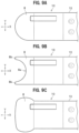
FIGS. 9A, 9B and 9C are partial plan views of a Helmholtz resonator showing modifications of an end part of the Helmholtz resonator in a wheel circumferential direction.
DETAILED DESCRIPTION OF THE PREFERRED EMBODIMENTS
Hereinafter, vehicle wheels according to embodiments of the present invention will be described in detail with reference to the drawings as appropriate.
In the description below, overall structure of a vehicle wheel will be first described, and then description will be given of a sub-air chamber member serving as a Helmholtz resonator and of a mounting structure of the sub-air chamber member on a rim by an adhesive material. Note that in FIG. 1 to FIG. 9 to be referred to, reference sign “X” denotes a wheel circumferential direction; reference sign “Y” denotes a wheel width direction; and reference sign “Z” denotes a wheel radial direction. Moreover, in the wheel width direction Y, an inner side is defined as “one side” and an outer side is defined as “other side”.
Overall Structure of Vehicle Wheel
FIG. 1 is a perspective view of a vehicle wheel 1 according to an embodiment of the present invention.
As shown in FIG. 1 , the vehicle wheel 1 according to the present embodiment is configured to allow an sub-air chamber member 10 (Helmholtz resonator) made of a synthetic resin such as polyamide resin to be mounted on a rim 11 made of metal such as aluminum alloy and magnesium alloy.
Moreover, the vehicle wheel 1 is provided with a stopper 41 as described in detail later.
In FIG. 1 , reference sign 12 denotes a disk 12 for connecting the rim 11 to a hub (not shown).
The rim 11 includes a well part 11 c which is recessed inward (toward a rotation center) in the wheel radial direction between bead seats (not shown) formed on both end parts of the rim 11 in the wheel width direction Y. An outer circumferential surface 11 d of the well part 11 c is defined by a bottom face of the concave part and has substantially the same diameter on the wheel shaft throughout the wheel width direction Y.
The rim 11 in the present embodiment is provided with a vertical wall 15 a and a vertical wall 15 b. The vertical walls 15 a, 15 b rise from the outer circumferential surface 11 d outward in the wheel radial direction with a predetermined distance between each other in the wheel width direction Y. Note that the rim 11 in the present embodiment is not limited to this configuration, but may adopt configuration not having the vertical walls 15 a, 15 b as described later.
The vertical wall 15 a formed at the one side (inner side) in the wheel width direction Y is formed in a rising part 17 that erects from the outer circumferential surface 11 d of the well part 11 c toward a rim flange side. Moreover, the vertical wall 15 b is configured by a circumferential wall 19 that extends in the wheel circumferential direction X at the middle in the wheel width direction Y of the outer circumferential surface 11 d. Note that in the description below, the vertical walls 15 a, 15 b are each simply referred to as a vertical wall 15 where they are not particularly distinguished from each other.
The vertical walls 15 a, 15 b annularly extend in the wheel circumferential direction X with a predetermined distance between each other, thereby forming side faces 14 (see FIG. 3 ) that face each other as described later. The side faces 14 are formed so that an angle between each of the side faces 14 and the outer circumferential surface 11 d (see FIG. 3 ) is substantially a right angle.
Sub-Air Chamber Member
Next, the sub-air chamber member 10 will be described.
FIG. 2 is an overall perspective view of the sub-air chamber member 10. FIG. 3 is a sectional view taken along the III-III line in FIG. 1 . FIG. 4 is a partially omitted and enlarged longitudinal sectional view taken along the IV-IV line in FIG. 3 .
As shown in FIG. 2 , the sub-air chamber member 10 is a member elongated in the wheel circumferential direction X and includes a main body 13, a tubular body 18 and a plate-like extension part 8. The sub-air chamber member 10 is configured to have a symmetric shape in the wheel circumferential direction X with respect to a partition wall 16 that extends in the wheel width direction Y at the center of the main body 13.
The main body 13 is curved in a longitudinal direction thereof. In other words, the main body 13 is configured to follow the wheel circumferential direction X when the sub-air chamber member 10 is mounted on the outer circumferential surface 11 d (see FIG. 1 ) of the well part 11 c (see FIG. 1 ).
The main body 13 has a hollow part inside. The hollow part (not shown) forms a sub-air chamber SC (see FIG. 3 ) as described later. The hollow part is divided by the partition wall 16 into two parts in the wheel circumferential direction X.
As shown in FIG. 3 , the main body 13 has a nearly rectangular shape elongated in the wheel width direction Y in cross section orthogonal to the longitudinal direction (the wheel circumferential direction X in FIG. 2 ).
More specifically, the main body 13 has configuration in which a bottom part 25 b (bottom plate) that is disposed along the outer circumferential surface 11 d of the well part 11 c, side parts 25 c (side plates) that are disposed along the side faces 14 of the pair of vertical walls 15, and an upper part 25 a (upper plate) that is disposed to face the bottom part 25 b, are mutually connected so as to form a nearly rectangular shape.
Thus, the upper part 25 a, the bottom part 25 b and the side parts 25 c are formed to surround the sub-air chamber SC inside the main body 13.
Between the outer circumferential surface 11 d of the well part 11 c and the bottom part 25 b, clearances of predetermined gaps are formed so that an adhesive material 21 having film thicknesses as described later can be interposed.
In the present embodiment, a height of the main body 13 from the outer circumferential surface 11 d (height in the wheel radial direction Z) is the same as a height of the vertical wall 15. Moreover, a width of the main body 13 (length in the wheel width direction Y) is set to a length at which the main body 13 is fitted between the vertical wall 15 a and the vertical wall 15 b.
Moreover, on the premise that the main body 13 is press-fitted between the vertical walls 15 a, 15 b, the width of the main body 13 may be set to be longer than a distance between the vertical walls 15 a, 15 b to such an extent that the main body 13 receives reaction force from the vertical walls 15 a, 15 b. In this case, the width of the main body 13 is preferably set so as not to allow volume of the sub-air chamber SC after the press-fitting to depart from designed volume.
As shown in FIG. 2 , the main body 13 has a plurality of (in this embodiment, ten) bridges 33 formed to be arranged at equal intervals in the wheel circumferential direction X. Moreover, the bridges 33 are arranged in two rows in the wheel width direction Y.
As shown in FIG. 3 , the bridges 33 are each formed with an upper side connecting part 33 a and a lower side connecting part 33 b being joined together at a nearly central position between the upper part 25 a and the bottom part 25 b.
Note that the upper side connecting part 33 a is formed so as to allow the upper part 25 a to be partially recessed toward the bottom part 25 b. Moreover, the lower side connecting part 33 b is formed so as to allow the bottom part 25 b to be partially recessed toward the upper part 25 a.
The upper side connecting part 33 a and the lower side connecting part 33 b are joined together via a joining part 33 c which is formed to be displaced to the outer circumferential surface 11 d side of the well part 11 c from the central part between the upper part 25 a and the bottom part 25 b.
The bridge 33 has a nearly cylindrical shape and partially connects the upper part 25 a with the bottom part 25 b. Moreover, the bridge 33 forms circular openings in planar view at corresponding positions in the up-down direction of the main body 13.
Moreover, the main body 13 has an inclined part 25 d at an end part thereof in the wheel circumferential direction X as shown in FIG. 2 .
On the inner side of the inclined part 25 d, the sub-air chamber SC is formed to allow volume thereof to be gradually reduced from the central part in the wheel circumferential direction X of the main body 13 toward an edge in the wheel circumferential direction X of the main body 13, i.e., toward a leading end Le of the main body 13.
More specifically, as shown in FIG. 4 , the inclined part 25 d is formed by allowing the upper part 25 a of the main body 13 to be displaced so as to gradually come near the bottom part 25 b as the upper part 25 a extends toward the leading end Le of the main body 13, and allowing the upper part 25 a and the bottom part 25 b to be connected together at the leading end Le.
The inclined part 25 d has an inclination angle θ which is preferably less than 45 degrees and more preferably equal to or less than 30 degrees. Note that, when a connecting point P between the upper part 25 a and the inclined part 25 d is defined in side view of the main body 13 in FIG. 4 , the inclination angle θ in the present embodiment means an angle formed on a narrow-angle side between the inclined part 25 d and a perpendicular line L2 that intersects at the connecting point P a line segment L1 that connects the connecting point P with a rotation center (not shown) of the wheel.
Next, the tubular body 18 (see FIG. 1 ) will be described.
As shown in FIG. 1 , the tubular body 18 is formed at a position biased to the one side (the inner side of the vehicle wheel 1) in the wheel width direction Y on the main body 13 so as to protrude from the main body 13 in the wheel circumferential direction X.
The sub-air chamber member 10 in the present embodiment is formed, as described above, into a symmetric shape in the wheel circumferential direction X with respect to the partition wall 16. Accordingly, although only one tubular body 18 is shown in FIG. 1 , the tubular bodies 18 in the present embodiment are disposed to form a pair at positions symmetrical to each other on both end parts in the longitudinal direction (the wheel circumferential direction X) of the main body 13.
As shown in FIG. 2 , the tubular body 18 has a communication hole 18 a formed inside.
The communication hole 18 a allows the sub-air chamber SC (see FIG. 3 ) formed inside the main body 13 to be communicated with a tire air chamber 9 (see FIG. 3 ) which is to be formed between the well part 11 c (see FIG. 3 ) and a tire (not shown).
Next, the plate-like extension part 8 (see FIG. 1 ) will be described.
As shown in FIG. 1 , the plate-like extension part 8 extends from the leading end Le of the main body 13 in the wheel circumferential direction X.
As shown in FIG. 2 , the plate-like extension part 8 is composed of a plate-like body having a rectangular shape in planar view and formed with nearly the same width as the main body 13 in the wheel width direction Y.
The plate-like extension part 8 is curved in the wheel circumferential direction X. That is, the plate-like extension part 8 is configured to follow the wheel circumferential direction X with a predetermined gap when the sub-air chamber member 10 is mounted on the outer circumferential surface 11 d (see FIG. 1 ) of the well part 11 c (see FIG. 1 ).
More specifically, in side view of the main body 13 in FIG. 4 , the plate-like extension part 8 in the present embodiment extends in the wheel circumferential direction X so as to have a slightly longer radius of curvature than a radius of curvature in the wheel circumferential direction X of the bottom part 25 b, depending on film thicknesses T1, T2 (see FIG. 6 ) of the adhesive material 21 as described later.
The sub-air chamber member 10 in the present embodiment is a blow molded product using a synthetic resin such as polyamide resin as described above. Note that the above synthetic resin is not specifically limited, but polyamide resin containing polyamide MXD6 (Registered trade mark) as a base resin, and nylon 6 are especially preferably used.
Mounting Structure of Sub-Air Chamber Member
Next, description will be given of a mounting structure of the sub-air chamber member 10 (see FIG. 1 ) on the rim 11 (see FIG. 1 ).
As shown in FIG. 3 , the sub-air chamber member 10 allows the bottom part 25 b of the main body 13 and the outer circumferential surface 11 d of the well part 11 c to be connected via the adhesive material 21 in the wheel width direction Y.
Moreover, as shown in FIG. 4 , the sub-air chamber member 10 allows a lower surface of the plate-like extension part 8 and the outer circumferential surface 11 d of the well part 11 c to be connected via the adhesive material 21, in addition to adhesion of the main body 13 to the outer circumferential surface 11 d, in the wheel circumferential direction X.
Examples of the adhesive material 21 include thermoplastic resin-based adhesive such as ethylene-vinyl acetate resin; thermosetting resin-based adhesive such as epoxy resin, polyurethane resin and polyamide resin; and elastomer-based adhesive such as synthetic rubber and thermoplastic elastomer, but the adhesive material is not limited to these examples.
Incidentally, the form of hardening of the adhesive material 21 is not specifically limited, but chemical reaction hardening is especially preferably used.
The adhesive material 21 can be coated on either the sub-air chamber member 10 or the rim 11. Moreover, the adhesive material 21 can also be coated on both of the sub-air chamber member 10 and the rim 11.
Examples of coating method for the adhesive material 21 include bar coating method, roll coating method, spray coating method, brush coating method, and hot-melt coating method, but the coating method is not limited to these examples.
Next, film thicknesses of the adhesive material 21 will be described.
The vehicle wheel 1 (see FIG. 1 ) according to the present embodiment allows a thickness of the adhesive material 21 (see FIG. 3 ) on a part of the sub-air chamber member 10 on which centrifugal force acts strongly during rotation of the wheel to be thicker than a thickness of the adhesive material 21 on other parts of the sub-air chamber member 10.
Herein, “the part on which the centrifugal force acts strongly” means a part at which materials (e.g., synthetic resin) forming the sub-air chamber member 10 unevenly exist, especially a part at which the materials unevenly exist on the outer side in the wheel radial direction Z, in accordance with the expression of centrifugal force F (F=mrω2: where m is mass of a mass point in the sub-air chamber member; r is a distance of the mass point from the rotation center of the wheel; and ω is an angle velocity of the mass point).
More specifically, where a regular part of the sub-air chamber member 10 facing the outer circumferential surface 11 d of the well part 11 c, i.e., the bottom part 25 b of the sub-air chamber member 10 is defined as a reference part, “the part on which the centrifugal force acts strongly” is directed to a part on which the centrifugal force acts more strongly than the reference part, e.g., a part at which the bridge 33 shown in FIG. 3 is formed, a part at which the side part 25 c is formed, and the plate-like extension part 8 shown in FIG. 4 .
Hereinafter, the present invention will be described in detail, taking as an example the case in which the adhesive material 21 is thickly applied on “the formation part of the bridge 33” and “the plate-like extension part 8” as “the part on which the centrifugal force acts strongly”.
As shown in FIG. 3 , the vehicle wheel 1 according to the present embodiment includes a regular part 7 a (the bottom part 25 b as the reference part) of the sub-air chamber member 10 (Helmholtz resonator), and an adhesive strength increasing part 7 b that is a part (the formation part of the bridge 33) on which the centrifugal force acts more strongly than the regular part 7 a during rotation of the wheel, and on which the adhesive material 21 is coated more thickly than the regular part 7 a.
FIG. 5 is a partially enlarged sectional view of the part V indicated by an arrow in FIG. 3 .
As shown in FIG. 5 , the adhesive strength increasing part 7 b is formed of an opposed surface of the main body 13 that faces the outer circumferential surface 11 d of the well part 11 c at a lower place of the bridge 33. Moreover, the regular part 7 a is formed of part of an opposed surface of the bottom part 25 b that faces the outer circumferential surface 11 d of the well part 11 c, i.e., the opposed surface exclusive of the adhesive strength increasing part 7 b.
Above the adhesive strength increasing part 7 b thus formed, the bridge 33 is located unlike the regular part 7 a. That is, centrifugal force according to the amount of materials (e.g., mass of synthetic resin) forming the bridge 33 is generated in the adhesive strength increasing part 7 b. Consequently, as described above, the centrifugal force acts more strongly on the adhesive strength increasing part 7 b than on the regular part 7 a above which the bridge 33 is not located.
Moreover, the adhesive material 21 is more thickly coated on the adhesive strength increasing part 7 b than on the regular part 7 a.
Moreover, as described above, the joining part 33 c of the bridge 33 is formed to be displaced to the outer circumferential surface 11 d side of the well part 11 c from the central part between the upper part 25 a (see FIG. 3 ) and the bottom part 25 b (see FIG. 3 ).
Although not shown, the inside of a lower part of the bridge 33 thus formed, i.e., the inside of the lower side connecting part 33 b can be filled with the adhesive material 21.
Next, film thicknesses of the adhesive material 21 around the plate-like extension part 8 will be described.
As shown in FIG. 4 , the vehicle wheel 1 (see FIG. 1 ) according to the present embodiment allows the film thickness of the adhesive material 21 between the outer circumferential surface 11 d of the well part 11 c and the plate-like extension part 8 to be thicker than the film thickness of the adhesive material 21 between the outer circumferential surface 11 d of the well part 11 c and the bottom part 25 b of the main body 13.
FIG. 6 is a partially enlarged sectional view of the part VI indicated by an arrow in FIG. 4 .
As shown in FIG. 6 , the sub-air chamber member 10 (Helmholtz resonator) has a stepped part S1 formed to be away from the outer circumferential surface 11 d of the well part 11 c (the wheel), at an end part of the Helmholtz resonator in the wheel circumferential direction X. The stepped part S1 is formed by a difference between a distance from the outer circumferential surface 11 d of the well part 11 c to the plate-like extension part 8 and a distance from the outer circumferential surface 11 d of the well part 11 c to the bottom part 25 b of the main body 13.
The adhesive material 21 is interposed between the plate-like extension part 8 and the outer circumferential surface 11 d, and between the bottom part 25 b and the outer circumferential surface 11 d.
More specifically, the adhesive material 21 having the film thickness T1 is interposed between the bottom part 25 b and the outer circumferential surface 11 d, and the adhesive material 21 having the film thickness T2 thicker than the film thickness T1 depending on the stepped part S1 is interposed between the plate-like extension part 8 and the outer circumferential surface 11 d.
Note that in FIG. 6 , reference sign 15 denotes the vertical wall of the rim 11; reference sign 18 denotes the tubular body; and reference sign 25 d denotes the inclined part of the main body 13.
Operation and Effects
Next, description will be given of operation and effects of the vehicle wheel 1 according to the present embodiment.
The vehicle wheel 1 according to the present embodiment allows the sub-air chamber member 10 (Helmholtz resonator) to be mounted on the rim 11 with the adhesive material 21.
The vehicle wheel 1 thus configured differs from the conventional vehicle wheel (for example, see Patent document 1) and has no need to cut and form a circumferential groove for mounting the sub-air chamber member 10 on the rim 11. Accordingly, the vehicle wheel 1 makes it possible to simplify a manufacturing process to reduce a manufacturing cost as compared to the conventional art.
The vehicle wheel 1 according to the present embodiment allows a thickness of the adhesive material 21 on the part of the sub-air chamber member 10 on which the centrifugal force acts strongly during rotation of the wheel to be thicker than a thickness of the adhesive material 21 on the other parts of the sub-air chamber member 10.
On the adhesive material 21 in the vehicle wheel 1, the centrifugal force acts in a peeling direction. In contrast, peel strength [N/mm] of the adhesive material 21 becomes higher unlike shear strength [N/mm2] as the film thickness becomes thicker.
The vehicle wheel 1 according to the present embodiment allows the adhesive material 21 to be thickly applied on the part on which the centrifugal force acts strongly, thereby making it possible to further enhance the fixing strength of the sub-air chamber member 10 to the rim 11.
Moreover, in the vehicle wheel 1, the sub-air chamber member 10 has the plate-like extension part 8 provided at the end part thereof in the wheel circumferential direction X, the plate-like extension part 8 being adhered on the outer circumferential surface 11 d of the well part 11 c (the wheel).
Herein, suppose the film thickness as the adhesive material 21 interposed between the outer circumferential surface 11 d of the well part 11 c and the main body 13 of the sub-air chamber member 10 is constant. Moreover, suppose the centrifugal force acting on the sub-air chamber member 10 during rotation of the wheel is applied equally in the wheel circumferential direction X.
Shear adhesion of the main body 13 obtained by the adhesive material 21 on the outer circumferential surface 11 d is weaker in an adhesive part at the end part in the wheel circumferential direction X of the main body 13 than in an arbitrary adhesive part at the middle part in the wheel circumferential direction X of the main body 13. That is, the end part of the main body 13 is more easily peeled off by the centrifugal force than the middle part.
In contrast, the vehicle wheel 1 according to the present embodiment has the plate-like extension part 8 adhered on the outer circumferential surface 11 d of the well part 11 c as described above, thus allowing shear adhesion of the sub-air chamber member 10 to the outer circumferential surface 11 d of the well part 11 c to be further enhanced when the centrifugal force acts on the sub-air chamber member 10.
Note that the plate-like extension part 8 is located on the more outer side than the bottom part 25 b in the wheel radial direction Z, thereby constituting the adhesive strength increasing part 7 b relative to the bottom part 25 b as the regular part 7 a as described above.
Moreover, in the vehicle wheel 1, the film thickness T2 of the adhesive material 21 on the part in which the stepped part S1 of the sub-air chamber member 10 is formed, i.e., on the plate-like extension part 8, is set to be thicker than the film thickness T1 of the adhesive material 21 on the other parts, i.e., on the bottom part 25 b of the main body 13.
The vehicle wheel 1 thus configured allows fixing strength of the plate-like extension part 8 to the outer circumferential surface 11 d of the well part 11 c to be further enhanced, thereby allowing shear adhesion of the sub-air chamber member 10 to the outer circumferential surface 11 d of the well part 11 c to be extremely enhanced.
Moreover, in the vehicle wheel 1, the volume of the sub-air chamber SC is gradually reduced from the central part in the wheel circumferential direction X of the main body 13 toward the edge in the wheel circumferential direction X of the main body 13, i.e., toward the leading end Le of the main body 13 shown in FIG. 4 .
The vehicle wheel 1 thus configured allows the upper part 25 a of the main body 13 to be displaced so as to gradually come near the bottom part 25 b as the upper part 25 a extends toward the leading end Le of the main body 13.
That is, the distance r from the rotation center of the mass point (m) of materials forming the upper part 25 a, in other words, of the mass point (m) being a constituent element of the centrifugal force (mrω2, where ω is a turning angle velocity) becomes shorter as the upper part 25 a extends toward the leading end Le of the main body 13. As a result, the centrifugal force acting on the main body 13 becomes smaller as the upper part 25 a extends toward the leading end Le.
Accordingly, the vehicle wheel 1 allows shear adhesion of the sub-air chamber member 10 to the outer circumferential surface 11 d to be further enhanced at the end part in the wheel circumferential direction X of the main body 13.
Moreover, in the vehicle wheel 1 according to the present embodiment, the upper part 25 a of the main body 13 is connected via the bridge 33 to the bottom part 25 b that is adhered and restrained on the outer circumferential surface 11 d of the well part 11 c. That is, the upper part 25 a is rigidly supported via the bridge 33 and the bottom part 25 b on the outer circumferential surface 11 d of the well part 11 c. This makes it possible, even if the centrifugal force F acts on the sub-air chamber member 10, to more reliably inhibit the upper part 25 a from swelling out in the centrifugal direction.
Accordingly, the sub-air chamber member 10 thus configured makes it possible to more reliably prevent a change in the volume of the sub-air chamber SC. In other words, the vehicle wheel 1 provided with the sub-air chamber member 10 makes it possible to more reliably maintain a designed proper resonance frequency in the sub-air chamber member 10.
Moreover, in the vehicle wheel 1 according to the present embodiment, the joining part 33 c of the bridge 33 between the bottom part 25 b and the upper part 25 a is formed to be displaced to the outer circumferential surface 11 d side (the wheel side) of the well part 11 c.
The inside of the lower side connecting part 33 b of the bridge 33 thus formed can also be filled with the adhesive material 21 as described above.
The vehicle wheel 1 thus configured also makes it possible to increase the film thickness of the adhesive material 21 to enhance the peel strength of the adhesive material 21.
Although the embodiment of the present invention has been described above, the present invention is not limited to the above embodiment and can be put into practice in various forms.
FIG. 7 is a partially enlarged sectional view of the periphery of a lower part of the bridge 33 in the vehicle wheel 1 according to a first modification. FIG. 8 is a partially enlarged sectional view of the periphery of a lower part of the bridge 33 in the vehicle wheel 1 according to a second modification. Note that in FIG. 7 and FIG. 8 , the same constituent element as in the above embodiment is given the same reference sign and thus detailed explanation thereof is omitted.
As shown in FIG. 7 , the vehicle wheel 1 according to the first modification has a stepped part S2 provided at the lower place of the bridge 33 of the main body 13, the stepped part S2 being formed so as to diameter-enlarging an opening of the lower part of the lower side connecting part 33 b. Formation of the stepped part S2 allows a cylindrical diameter-enlarged space to be formed inside the lower part of the lower side connecting part 33 b.
The cylindrical space is filled with the adhesive material 21, thereby allowing the film thickness of the adhesive material 21 filled into the cylindrical space to be thicker than the film thickness of the adhesive material 21 on the bottom part 25 b of the main body 13.
The vehicle wheel 1 thus configured makes it possible to more reliably apply the adhesive material 21 thickly on the lower place of the bridge 33 on which centrifugal force acts strongly. This makes it possible for the vehicle wheel 1 to further enhance the fixing strength of the sub-air chamber member 10 to the outer circumferential surface 11 d of the well part 11 c.
As shown in FIG. 8 , the vehicle wheel 1 according to the second modification has an elastic foamed member 6 filled inside the lower side connecting part 33 b. The elastic foamed member 6 is filled through the opening of the lower side connecting part 33 b before the adhesive material 21 is applied on the sub-air chamber member 10.
The elastic foamed member 6 fills, of an internal space formed inside the lower side connecting part 33 b, the internal space of the lower side connecting part 33 b exclusive of a corner radius section 33 d that expands the opening of the lower side connecting part 33 b.
The adhesive material 21 is filled into only the corner radius section 33 d of the internal space of the lower side connecting part 33 b. Moreover, the adhesive material 21 is applied between the elastic foamed member 6 and the outer circumferential surface 11 d of the well part 11 c, with the same film thickness as the adhesive material 21 interposed between the bottom part 25 b of the main body 13 and the outer circumferential surface 11 d.
Examples of the elastic foamed member 6 include what is called a sponge consisting of a foamed body such as urethane resin, silicone resin and acrylic resin, but the elastic foamed member is not limited to these examples.
The vehicle wheel 1 thus configured prevents the adhesive material 21 from being filled into the entire internal space of the lower side connecting part 33 b. That is, the vehicle wheel 1 makes it possible to maintain flexibility of the sub-air chamber member 10 per se where the adhesive material 21 to be used is of a type not having elasticity after curing. Accordingly, the vehicle wheel 1 makes it possible to expand the width of selection of the type of the adhesive material 21 to be used.
Moreover, although the plate-like extension part 8 of the sub-air chamber member 10 shown in FIG. 2 in the above embodiment has a rectangular shape in planar view, the plate-like extension part 8 is not limited to this embodiment.
FIGS. 9A, 9B and 9C to be next referred to are partial plan views of the sub-air chamber member 10 showing modifications of the plate-like extension part 8 of the sub-air chamber member 10.
The plate-like extension part 8 shown in FIG. 9A has a semicircular shape such that a leading end side thereof in the wheel circumferential direction X forms an arc in planar view.
The sub-air chamber member 10 having the plate-like extension part 8 thus formed makes it possible to achieve size reduction of the plate-like extension part 8 while securing a sufficient adhesive surface thereof to the outer circumferential surface 11 d (see FIG. 1 ) of the well part 11 c (see FIG. 1 ).
The plate-like extension part 8 shown in FIG. 9B has a cut-out part 8 a of a semicircular shape such that the main body 13 side forms an arc in planar view.
The sub-air chamber member 10 having the plate-like extension part 8 thus formed makes it possible to secure adhesive surfaces at spots far away from the main body 13 in the wheel circumferential direction X, by a pair of extension parts 8 b across the cut-out part 8 a in the wheel width direction Y, and to achieve weight saving of the plate-like extension part 8 per se by the cut-out part 8 a.
According to the sub-air chamber member 10 having the plate-like extension part 8 thus formed, shear adhesion of the sub-air chamber member 10 to the outer circumferential surface 11 d (see FIG. 1 ) of the well part 11 c (see FIG. 1 ) can be further enhanced.
The plate-like extension part 8 shown in FIG. 9C has an oval shape with a long diameter in the wheel width direction Y in planar view.
The sub-air chamber member 10 having the plate-like extension part 8 thus formed allows an adhesive surface thereof to the outer circumferential surface 11 d (see FIG. 1 ) of the well part 11 c (see FIG. 1 ) to be increased, thus making it possible to enhance shear adhesion of the sub-air chamber member 10.
Moreover, although the vehicle wheel 1 in the above embodiment allows the main body 13 of the sub-air chamber member 10 to be disposed between the vertical wall 15 a and the vertical wall 15 b, configuration may be adopted such that at least one of the vertical wall 15 a and the vertical wall 15 b is omitted.
Although embodiments of the present invention have been described and illustrated in detail, the disclosed embodiments are made for purposes of illustration and example only and not limitation. The scope of the present invention should be interpreted by terms of the appended claims.
DESCRIPTION OF REFERENCE SIGNS
1: Vehicle wheel; 6: Elastic foamed member; 7 a: Regular part; 7 b: Adhesive strength increasing part; 8: Plate-like extension part; 8 a: Cut-out part; 8 b: Extension part; 9: Tire air chamber; 10: Sub-air chamber member; 11: Rim; 11 c: Well part; 11 d: Outer circumferential surface; 12: Disk; 13: Main body; 14: Side face; 15: Vertical wall; 15 a: Vertical wall; 15 b: Vertical wall; 16: Partition wall; 17: Rising part; 18: Tubular body; 18 a: Communication hole; 19: Circumferential wall; 21: Adhesive material; 25 a: Upper part; 25 b: Bottom part; 25 c: Side part; 25 d: Inclined part; 33: Bridge; 33 a: Upper side connecting part; 33 b: Lower side connecting part; 33 c: Joining part; 33 d: Corner radius section; F: Centrifugal force; Le: Leading end; P: Connecting point; S1: Stepped part; S2: Stepped part; SC: Sub-air chamber; T1: Film thickness; T2: Film thickness; X: Wheel circumferential direction; Y: Wheel width direction; Z: Wheel radial direction

Claims (5)

What is claimed is:
1. A vehicle wheel comprising a Helmholtz resonator mounted on a rim with an adhesive material, wherein
the rim includes a well part which is recessed inward in a wheel radial direction,
the Helmholtz resonator has a plate-like extension part provided at an end part thereof in a wheel circumferential direction of the Helmholtz resonator, the plate-like extension part extending in the wheel circumferential direction to be adhered on the rim,
the Helmholtz resonator has a stepped part formed to be away from the rim, at an end part in the wheel circumferential direction of the Helmholtz resonator, and
a thickness of the adhesive material on a part of the Helmholtz resonator in which the stepped part is formed is set to be thicker than a thickness of the adhesive material on other parts of the Helmholtz resonator.
2. The vehicle wheel according to claim 1, wherein the Helmholtz resonator is adhered to follow an outer circumferential surface of the well part, and
the Helmholtz resonator allows volume of a sub-air chamber thereof to be reduced from a central part toward an edge in the wheel circumferential direction of the Helmholtz resonator.
3. The vehicle wheel according to claim 1, wherein
the Helmholtz resonator is adhered to follow an outer circumferential surface of the well part, and includes:
a bottom part that is disposed at the outer circumferential surface side of the well part; an upper part that forms a sub-air chamber between the bottom part and the upper part; and a bridge that connects the bottom part with the upper part, and wherein
the Helmholtz resonator has the stepped part formed to be away from the rim, on a periphery of the bridge in the bottom part, and
the thickness of the adhesive material on a part of the Helmholtz resonator in which the stepped part is formed is set to be thicker than a thickness of the adhesive material on a periphery of the stepped part.
4. The vehicle wheel according to claim 1, wherein
the Helmholtz resonator is adhered to follow an outer circumferential surface of the well part, and includes:
a bottom part that is disposed at the outer circumferential surface side of the well part; an upper part that forms a sub-air chamber between the bottom part and the upper part; and a bridge that connects the bottom part with the upper part, and wherein
a joining part of the bridge between the bottom part and the upper part is formed to be displaced to the rim side.
5. The vehicle wheel according to claim 1, wherein
the Helmholtz resonator is adhered to follow an outer circumferential surface of the well part, and includes:
a bottom part that is disposed at the outer circumferential surface side of the well part; an upper part that forms a sub-air chamber between the bottom part and the upper part; and a bridge that connects the bottom part with the upper part, and wherein
an elastic foamed member is filled into the bridge through an opening of the bridge formed on the bottom part side.
US16/367,969 2018-04-02 2019-03-28 Vehicle wheel and Helmholtz resonator Active 2041-12-22 US11584159B2 (en)

Applications Claiming Priority (3)

Application Number Priority Date Filing Date Title
JP2018-071168 2018-04-02
JPJP2018-071168 2018-04-02
JP2018071168A JP7028693B2 (en) 2018-04-02 2018-04-02 Vehicle wheels

Publications (2)

Publication Number Publication Date
US20190299708A1 US20190299708A1 (en) 2019-10-03
US11584159B2 true US11584159B2 (en) 2023-02-21

Family

ID=68054710

Family Applications (1)

Application Number Title Priority Date Filing Date
US16/367,969 Active 2041-12-22 US11584159B2 (en) 2018-04-02 2019-03-28 Vehicle wheel and Helmholtz resonator

Country Status (3)

Country Link
US (1) US11584159B2 (en)
JP (1) JP7028693B2 (en)
CN (1) CN110341377B (en)

Families Citing this family (1)

* Cited by examiner, † Cited by third party
Publication number Priority date Publication date Assignee Title
JP2019217979A (en) * 2018-06-22 2019-12-26 本田技研工業株式会社 Vehicle wheel

Citations (23)

* Cited by examiner, † Cited by third party
Publication number Priority date Publication date Assignee Title
EP0663306A2 (en) * 1994-01-14 1995-07-19 Continental Aktiengesellschaft Motor vehicle wheel
JP2004306760A (en) * 2003-04-07 2004-11-04 Honda Motor Co Ltd Anti-resonance band for wheels
JP2006256535A (en) * 2005-03-18 2006-09-28 Rintekkusu Kk Wheel for vehicle
KR100777754B1 (en) * 2006-08-30 2007-11-20 한국타이어 주식회사 Rubber Wheels with Tire Tubes for Resonance Reduction
JP2008279911A (en) * 2007-05-11 2008-11-20 Honda Motor Co Ltd Vehicle wheel
US7896043B2 (en) * 2007-09-19 2011-03-01 Honda Motor Co., Ltd. Vehicle wheel with sub air chamber and pressure sensor
US7896044B2 (en) * 2007-10-26 2011-03-01 Honda Motor Co., Ltd. Vehicle wheel having a sub air chamber
JP2012045971A (en) 2010-08-24 2012-03-08 Nippon Plast Co Ltd Resonance preventing device for automotive wheel
US8490665B2 (en) * 2009-09-08 2013-07-23 Honda Motor Co., Ltd. Vehicle wheel
KR20130130343A (en) * 2012-05-22 2013-12-02 현대자동차주식회사 All-in-one sound absorbing aluminum wheel using molten core and its manufacturing method
JP2014201205A (en) * 2013-04-04 2014-10-27 三菱自動車工業株式会社 Vehicular wheel structure
US20140346843A1 (en) * 2013-05-21 2014-11-27 Honda Motor Co., Ltd. Vehicle wheel
US9545820B2 (en) * 2014-10-31 2017-01-17 GM Global Technology Operations LLC Wheel with aluminum foam for tire cavity noise suppression
US9694626B2 (en) * 2012-12-17 2017-07-04 Honda Motor Co., Ltd. Vehicle wheel
US9701157B2 (en) * 2013-02-28 2017-07-11 Honda Motor Co., Ltd. Vehicle wheel
KR20180013177A (en) * 2016-07-28 2018-02-07 핸즈코퍼레이션주식회사 The multi-resonator
US20190275847A1 (en) * 2018-03-09 2019-09-12 Honda Motor Co., Ltd. Vehicle wheel
US20190299707A1 (en) * 2018-04-02 2019-10-03 Honda Motor Co., Ltd. Vehicle wheel
JP2019199094A (en) * 2018-05-14 2019-11-21 本田技研工業株式会社 Wheel for vehicle and method of manufacturing the same
US20190366763A1 (en) * 2018-06-01 2019-12-05 Honda Motor Co., Ltd. Vehicle wheel
US10504500B2 (en) * 2015-03-19 2019-12-10 Honda Motor Co., Ltd. Vehicle wheel
US20200009905A1 (en) * 2018-07-09 2020-01-09 Honda Motor Co., Ltd. Vehicle wheel
US11046111B2 (en) * 2016-03-16 2021-06-29 Honda Motor Co., Ltd. Vehicle wheel

Family Cites Families (9)

* Cited by examiner, † Cited by third party
Publication number Priority date Publication date Assignee Title
JP3441618B2 (en) * 1997-05-29 2003-09-02 ミヨタ株式会社 Plasma display device
JP2007309470A (en) * 2006-05-22 2007-11-29 Toyota Motor Corp Overlap adhesive joint
JP2010052700A (en) * 2008-08-29 2010-03-11 Nippon Plast Co Ltd Wheel for vehicle
JP2011057007A (en) * 2009-09-08 2011-03-24 Honda Motor Co Ltd Vehicular wheel
DE102012007990A1 (en) * 2011-10-10 2013-04-11 Volkswagen Aktiengesellschaft Rim, vehicle wheel and vehicle with such a rim
US9302537B2 (en) * 2013-08-16 2016-04-05 GM Global Technology Operations LLC Noise suppression device for a wheel assembly
GB2519749B (en) * 2013-10-24 2015-08-05 Bentley Motors Ltd Tyre cavity noise absorber
JP6348736B2 (en) * 2014-03-13 2018-06-27 本田技研工業株式会社 Vehicle wheel
KR20160116741A (en) * 2015-03-31 2016-10-10 현대자동차주식회사 Wheel resonator for vehicle

Patent Citations (23)

* Cited by examiner, † Cited by third party
Publication number Priority date Publication date Assignee Title
EP0663306A2 (en) * 1994-01-14 1995-07-19 Continental Aktiengesellschaft Motor vehicle wheel
JP2004306760A (en) * 2003-04-07 2004-11-04 Honda Motor Co Ltd Anti-resonance band for wheels
JP2006256535A (en) * 2005-03-18 2006-09-28 Rintekkusu Kk Wheel for vehicle
KR100777754B1 (en) * 2006-08-30 2007-11-20 한국타이어 주식회사 Rubber Wheels with Tire Tubes for Resonance Reduction
JP2008279911A (en) * 2007-05-11 2008-11-20 Honda Motor Co Ltd Vehicle wheel
US7896043B2 (en) * 2007-09-19 2011-03-01 Honda Motor Co., Ltd. Vehicle wheel with sub air chamber and pressure sensor
US7896044B2 (en) * 2007-10-26 2011-03-01 Honda Motor Co., Ltd. Vehicle wheel having a sub air chamber
US8490665B2 (en) * 2009-09-08 2013-07-23 Honda Motor Co., Ltd. Vehicle wheel
JP2012045971A (en) 2010-08-24 2012-03-08 Nippon Plast Co Ltd Resonance preventing device for automotive wheel
KR20130130343A (en) * 2012-05-22 2013-12-02 현대자동차주식회사 All-in-one sound absorbing aluminum wheel using molten core and its manufacturing method
US9694626B2 (en) * 2012-12-17 2017-07-04 Honda Motor Co., Ltd. Vehicle wheel
US9701157B2 (en) * 2013-02-28 2017-07-11 Honda Motor Co., Ltd. Vehicle wheel
JP2014201205A (en) * 2013-04-04 2014-10-27 三菱自動車工業株式会社 Vehicular wheel structure
US20140346843A1 (en) * 2013-05-21 2014-11-27 Honda Motor Co., Ltd. Vehicle wheel
US9545820B2 (en) * 2014-10-31 2017-01-17 GM Global Technology Operations LLC Wheel with aluminum foam for tire cavity noise suppression
US10504500B2 (en) * 2015-03-19 2019-12-10 Honda Motor Co., Ltd. Vehicle wheel
US11046111B2 (en) * 2016-03-16 2021-06-29 Honda Motor Co., Ltd. Vehicle wheel
KR20180013177A (en) * 2016-07-28 2018-02-07 핸즈코퍼레이션주식회사 The multi-resonator
US20190275847A1 (en) * 2018-03-09 2019-09-12 Honda Motor Co., Ltd. Vehicle wheel
US20190299707A1 (en) * 2018-04-02 2019-10-03 Honda Motor Co., Ltd. Vehicle wheel
JP2019199094A (en) * 2018-05-14 2019-11-21 本田技研工業株式会社 Wheel for vehicle and method of manufacturing the same
US20190366763A1 (en) * 2018-06-01 2019-12-05 Honda Motor Co., Ltd. Vehicle wheel
US20200009905A1 (en) * 2018-07-09 2020-01-09 Honda Motor Co., Ltd. Vehicle wheel

Also Published As

Publication number Publication date
JP7028693B2 (en) 2022-03-02
CN110341377B (en) 2022-09-20
JP2019182000A (en) 2019-10-24
CN110341377A (en) 2019-10-18
US20190299708A1 (en) 2019-10-03

Similar Documents

Publication Publication Date Title
US11642919B2 (en) Vehicle wheel
US11548328B2 (en) Vehicle wheel
US20200009905A1 (en) Vehicle wheel
JP4551422B2 (en) Vehicle wheel
JP4834715B2 (en) Vehicle wheel
US7896043B2 (en) Vehicle wheel with sub air chamber and pressure sensor
US6637832B2 (en) Wheel and cladding
US9566825B2 (en) Vehicle wheel
JP2005170379A (en) Run-flat device for automobile and mounting assembly incorporating the same
US11584159B2 (en) Vehicle wheel and Helmholtz resonator
US11554730B2 (en) Vehicle wheel
US20200023684A1 (en) Vehicle wheel
US11505012B2 (en) Vehicle wheel
US20190366763A1 (en) Vehicle wheel
US20190299707A1 (en) Vehicle wheel
US20190389247A1 (en) Vehicle wheel
US20200164683A1 (en) Vehicle wheel
US11440345B2 (en) Vehicle wheel
GB2388416A (en) Fluid-filled vibration-damping device
US20200023683A1 (en) Vehicle wheel
US6427989B1 (en) Vibration-isolating apparatus
CN106715959B (en) Self-adhesive balancing weight for vehicle wheels
US6843286B1 (en) Tire/wheel assembly, run-flat support member and manufacturing method therefor
KR102600783B1 (en) Pneumatic tire with sound absorbing member
JP2020006779A (en) Vehicular wheel

Legal Events

Date Code Title Description
AS Assignment

Owner name: HONDA MOTOR CO., LTD., JAPAN

Free format text: ASSIGNMENT OF ASSIGNORS INTEREST;ASSIGNORS:NISHI, MASAAKI;KAMIYAMA, YOUICHI;SAITO, TOSHINOBU;AND OTHERS;REEL/FRAME:048732/0263

Effective date: 20190325

FEPP Fee payment procedure

Free format text: ENTITY STATUS SET TO UNDISCOUNTED (ORIGINAL EVENT CODE: BIG.); ENTITY STATUS OF PATENT OWNER: LARGE ENTITY

STPP Information on status: patent application and granting procedure in general

Free format text: NON FINAL ACTION MAILED

STPP Information on status: patent application and granting procedure in general

Free format text: RESPONSE TO NON-FINAL OFFICE ACTION ENTERED AND FORWARDED TO EXAMINER

STPP Information on status: patent application and granting procedure in general

Free format text: NOTICE OF ALLOWANCE MAILED -- APPLICATION RECEIVED IN OFFICE OF PUBLICATIONS

STCF Information on status: patent grant

Free format text: PATENTED CASE