JP2014201205A - Vehicular wheel structure - Google Patents

Vehicular wheel structure Download PDF

Info

Publication number
JP2014201205A
JP2014201205A JP2013078928A JP2013078928A JP2014201205A JP 2014201205 A JP2014201205 A JP 2014201205A JP 2013078928 A JP2013078928 A JP 2013078928A JP 2013078928 A JP2013078928 A JP 2013078928A JP 2014201205 A JP2014201205 A JP 2014201205A
Authority
JP
Japan
Prior art keywords
wheel
tire
damper member
rim
air chamber
Prior art date
Legal status (The legal status is an assumption and is not a legal conclusion. Google has not performed a legal analysis and makes no representation as to the accuracy of the status listed.)
Pending
Application number
JP2013078928A
Other languages
Japanese (ja)
Inventor
拓也 養父
Takuya Yabu
拓也 養父
中村 浩之
Hiroyuki Nakamura
浩之 中村
Current Assignee (The listed assignees may be inaccurate. Google has not performed a legal analysis and makes no representation or warranty as to the accuracy of the list.)
Mitsubishi Motors Corp
Original Assignee
Mitsubishi Motors Corp
Priority date (The priority date is an assumption and is not a legal conclusion. Google has not performed a legal analysis and makes no representation as to the accuracy of the date listed.)
Filing date
Publication date
Application filed by Mitsubishi Motors Corp filed Critical Mitsubishi Motors Corp
Priority to JP2013078928A priority Critical patent/JP2014201205A/en
Publication of JP2014201205A publication Critical patent/JP2014201205A/en
Pending legal-status Critical Current

Links

Images

Abstract

PROBLEM TO BE SOLVED: To provide a vehicular wheel structure provided with a multipurpose wheel damper which can achieve reduction of sound in a cabin and is good in fitting performance to a wheel.SOLUTION: A wheel 1, a tire 3 fitted to its rim 2 and an air chamber 4 enclosed by the tire and the rim are formed, and provided is a damper member 6 which is faced to the air chamber, is mated with and supported by the rim of the wheel, and includes an annular main part 5 of a prescribed thickness in a wheel radial direction r. The damper member is formed so as to include at least two functions parts of a resonator 8 which is provided in the annular main room and in which obtained is a function of a resonant chamber that can lower acoustic pressure in a tire air chamber, a dynamic vibration absorber 11 in which obtained is vibration control function by projection-like protruding parts 9 that are formed in the annular main part and are divided to each other in a circular direction, and an air column resonant attenuation part 12 in which obtained is sound-damping function by air column resonant frequency switching through the protruding parts 121 that are formed in the annular main part and narrow the space width in the closed cross section of the tire air chamber.

Description

本発明は、車両の車輪にホイールダンパが装着された車両の車輪構造、特に、ホイールダンパがホイールの外周部とタイヤに囲繞されるタイヤ空気室と対向配備される車両の車輪構造に関する。   The present invention relates to a vehicle wheel structure in which a wheel damper is mounted on a vehicle wheel, and more particularly to a vehicle wheel structure in which a wheel damper is disposed opposite to an outer peripheral portion of a wheel and a tire air chamber surrounded by a tire.

車両の車輪を成すタイヤとホイールは、エンジンからの回転力を受けて回転駆動するため、エンジンの発生するトルク変動がドライブシャフトを通じて伝わることで回転方向に振動(以下、回転変動)する。
また、路面からの変位入力によって回転方向(周方向)以外にも路面入力による振動を生じる。
さらに、タイヤ内部のタイヤ空気室での空気振動による気柱共鳴音が発生する。
これらの回転変動・路面入力振動・気柱共鳴音が車両のサスペンションや空気中を伝播して車体内部に伝わることで、車内音(こもり音やロードノイズ)や振動が生じている。
このように、車輪を成すタイヤとホイールが発生する回転変動・路面入力振動・気柱共鳴音を低減(小さく)するため、従来、例えば、特許文献1〜4の技術が知られている。
Since the tires and wheels that form the wheels of the vehicle are driven to rotate by receiving the rotational force from the engine, torque fluctuations generated by the engine are transmitted through the drive shaft and vibrate in the rotational direction (hereinafter referred to as rotational fluctuations).
In addition to the rotational direction (circumferential direction), vibration due to road surface input is generated by displacement input from the road surface.
Furthermore, air column resonance is generated by air vibration in the tire air chamber inside the tire.
These rotational fluctuations, road surface input vibrations, and air column resonance sounds propagate through the vehicle suspension and air to the interior of the vehicle body, thereby generating in-vehicle sounds (bulk noise and road noise) and vibrations.
Thus, in order to reduce (reduce) the rotational fluctuation, road surface input vibration, and air column resonance generated by the tires and wheels that form the wheels, for example, techniques of Patent Documents 1 to 4 are conventionally known.

特許文献1では、ホイールの周方向での剛性分布を変化させることで、ホイール振動の伝達を低減している。なお、ホイール上にダンパを設置しているが、剛性分布変化によるホイールバランスの偏りをこのダンパで調整することを主目的としている。
特許文献2では、環状振動部(インパクトダンパー)のマス部が筒状当接面に打ち当たることによって、ホイールの振動を直接的に低減して制振効果が発揮されるとしている。これにより回転変動やホイール振動を抑制している。
In Patent Document 1, the transmission of wheel vibration is reduced by changing the stiffness distribution in the circumferential direction of the wheel. Although the damper is installed on the wheel, the main purpose is to adjust the bias of the wheel balance due to the change in stiffness distribution.
In Patent Document 2, the mass portion of the annular vibration portion (impact damper) hits the cylindrical contact surface, thereby reducing the vibration of the wheel directly and exhibiting the vibration damping effect. This suppresses rotational fluctuations and wheel vibrations.

特許文献3では、ホイールのリムの外周面対向部やホイールに外嵌されるタイヤのトレッドの挟持空間部に吸音材(発砲ウレタン)を設置し、ホイール振動によってタイヤ空気室内部に発生するロードノイズを吸音材が吸音して低減している。
特許文献4では、気柱共鳴音によって発生したホイール振動の低減を図るようチューニングされたダイナミックダンパ(トーショナルダンパ)を設置している。ここでは、気柱共鳴音によって発生するロードノイズがホイールに伝達されず、ホイール振動は抑制されるが、気柱共鳴音が低減されるものではない。
In Patent Literature 3, a sound absorbing material (foamed urethane) is installed in an outer peripheral surface facing portion of a rim of a wheel or a holding space portion of a tire tread that is fitted on the wheel, and road noise generated in a tire air chamber due to wheel vibration. The sound absorbing material absorbs sound and is reduced.
In Patent Document 4, a dynamic damper (torsional damper) tuned to reduce wheel vibration generated by air column resonance is installed. Here, road noise generated by air column resonance is not transmitted to the wheel and wheel vibration is suppressed, but the air column resonance is not reduced.

特開平04−306101号公報Japanese Patent Laid-Open No. 04-306101 特開2004−148865号公報JP 2004-148865 A 特開昭63−275404号公報JP-A-63-275404 実開平01−050101号公報Japanese Utility Model Publication No. 01-050101

このように、特許文献1には、ホイール振動の伝達を低減するホイールディスクが開示されるのみであり、特許文献2には、ホイールの回転変動を抑制する車輪用制振装置が開示される。しかし、タイヤ空気室内部の騒音の音圧レベルを下げる共鳴室の機能や、タイヤ空気室での空気振動による気柱共鳴音を低減して気柱共鳴音が車内に伝搬して騒音の原因となることを防止する機能は開示されない。
特許文献3には音を伝達しにくい物質を通して音を低減する吸音材をタイヤ空気室に配したリム付タイヤが開示されるのみであり、特許文献4には気柱共鳴音によって発生するロードノイズによるホイール振動を抑制するホイール構造が開示されるのみである。これらには、タイヤ空気室内部の騒音の音圧レベルを下げる共鳴器の機能や、タイヤ空気室での空気振動による気柱共鳴音を低減することで、気柱共鳴音が車内に伝搬して騒音の原因となること、気柱共鳴音が直接車内に伝搬して騒音の原因となることを防止する機能は開示されない。なお、共鳴器は動吸振器と関連する原理で音を低減し、吸音材は音を伝達しにくい物質を通して音を低減するもので、いずれも音の減衰を図るが、減衰機能は相違する。
このように、特許文献1〜4には、回転変動を抑制するのに加えて、タイヤ空気室内のロードノイズを吸音材で抑制し、あるいは、タイヤ空気室内の気柱共鳴音によって発生したホイール振動を抑制するホイールダンパが開示される。しかし、抑制すべき車内音(騒音)の要因は複数ある。即ち、ホイールダンパが路面からの入力によるホイール振動に起因するロードノイズや、ホイールダンパがタイヤ空気室内の気柱共鳴音に起因するロードノイズや、駆動系からの回転変動に起因する騒音(こもり音)がある。そこで、これらの抑制すべき車内音(騒音)を同時に複数抑制するという多目的のホイールダンパを車輪に装着することが望ましい。
しかし、この場合、従来の技術では複数のホールダンパを必要とする。これでは、ホイールへの装着にあたり取り付けスペース確保や装着を可能とする構成部の作成に時間を要し、コスト増を招き、汎用化に問題が生じ易い。
Thus, Patent Document 1 only discloses a wheel disk that reduces transmission of wheel vibration, and Patent Document 2 discloses a wheel damping device that suppresses wheel rotation fluctuations. However, the function of the resonance chamber that lowers the sound pressure level of the noise inside the tire air chamber and the air column resonance sound caused by air vibration in the tire air chamber are reduced and the air column resonance sound propagates into the vehicle, causing noise. The function of preventing the occurrence of the error is not disclosed.
Patent Document 3 only discloses a tire with a rim in which a sound absorbing material that reduces sound through a substance that hardly transmits sound is disposed in the tire air chamber, and Patent Document 4 discloses road noise generated by air column resonance sound. Only a wheel structure that suppresses wheel vibration due to is disclosed. These include the function of a resonator that lowers the sound pressure level of the noise inside the tire air chamber and the reduction of air column resonance caused by air vibration in the tire air chamber, so that the air column resonance is propagated into the vehicle. The function of preventing noise and air column resonance from propagating directly into the vehicle and causing noise is not disclosed. The resonator reduces sound based on the principle related to the dynamic vibration absorber, and the sound absorbing material reduces sound through a substance that does not easily transmit sound. Both of them aim to attenuate sound, but the attenuation function is different.
As described above, in Patent Documents 1 to 4, in addition to suppressing rotational fluctuation, road noise in the tire air chamber is suppressed by the sound absorbing material, or wheel vibration generated by air column resonance sound in the tire air chamber. A wheel damper that suppresses this is disclosed. However, there are a number of factors causing in-vehicle noise (noise) to be suppressed. In other words, road noise caused by wheel vibration caused by wheel damper input from road surface, road noise caused by air column resonance in the tire air chamber, and noise caused by rotational fluctuations from the drive system (humid noise) ) Therefore, it is desirable to install a multi-purpose wheel damper that suppresses a plurality of these in-vehicle sounds (noise) to be suppressed at the wheel.
However, in this case, the conventional technique requires a plurality of hole dampers. In this case, it takes a long time to secure a mounting space and to create a component that can be mounted for mounting on the wheel, which increases costs and tends to cause problems in generalization.

本発明は以上のような課題を解決するため、回転変動、ホイール振動、気柱共鳴音の少なくとも2つを共に低減することで車内音低減を図れ、しかも、ホイールへの装着性がよい多目的ホイールダンパを備えた車両の車輪構造を提供する。   In order to solve the above-described problems, the present invention can reduce internal sound by reducing at least two of rotation fluctuation, wheel vibration, and air column resonance sound, and is a multi-purpose wheel that is easy to attach to a wheel. Provided is a vehicle wheel structure provided with a damper.

本願請求項1の発明は、ホイールと該ホイールのリムに装着されたタイヤと該タイヤとリムにより囲繞されるタイヤ空気室とを形成した車両の車輪構造において、前記タイヤ空気室と対向し前記ホイールのリムに外嵌支持されると共にホイール半径方向に所定厚さの環状主部を有したダンパ部材を備え、前記ダンパ部材は、前記環状主部の内部に前記タイヤ空気室の音圧を下げる共鳴室の機能が得られる共鳴器と、前記環状主部で形成され周方向に互いに区分された複数の突状膨出部により制振機能が得られる動吸振器と、前記環状主部の外側環状層で形成され前記タイヤ空気室の閉断面の空間幅を狭める膨出部により気柱共鳴周波数を切換え消音機能を得る気柱共鳴減衰部と、の内の少なくとも2つの機能部を有するよう形成された、ことを特徴とする。   The invention according to claim 1 is a vehicle wheel structure in which a wheel, a tire mounted on a rim of the wheel, and a tire air chamber surrounded by the tire and the rim are formed, and the wheel is opposed to the tire air chamber. And a damper member that has an annular main portion with a predetermined thickness in the radial direction of the wheel, and the damper member is a resonance that lowers the sound pressure of the tire air chamber inside the annular main portion. A resonator capable of functioning as a chamber, a dynamic vibration absorber capable of obtaining a damping function by a plurality of protruding bulges formed by the annular main part and separated from each other in the circumferential direction, and an outer ring of the annular main part The air column resonance attenuating part is configured to switch the air column resonance frequency by a bulging part that is formed of a layer and narrows the space width of the closed cross section of the tire air chamber, and is formed to have at least two functional parts. Was it And features.

本願請求項2の発明は、請求項1記載の車両の車輪構造において、前記ダンパ部材は、前記共鳴器と前記動吸振器との両機能部を有するよう形成された、ことを特徴とする。   According to a second aspect of the present invention, in the vehicle wheel structure according to the first aspect, the damper member is formed to have both functional parts of the resonator and the dynamic vibration absorber.

本願請求項3の発明は、請求項1記載の車両の車輪構造において、前記ダンパ部材は、前記動吸振器と前記気柱共鳴減衰部との両機能部を有するよう形成された、ことを特徴とする。   According to a third aspect of the present invention, in the vehicle wheel structure according to the first aspect, the damper member is formed so as to have both functional parts of the dynamic vibration absorber and the air column resonance attenuation part. And

本願請求項4の発明は、請求項1記載の車両の車輪構造において、前記ダンパ部材は、前記共鳴器と前記気柱共鳴減衰部との両機能部を有するよう形成された、ことを特徴とする。   According to a fourth aspect of the present invention, in the vehicle wheel structure according to the first aspect, the damper member is formed to have both functional parts of the resonator and the air column resonance attenuating part. To do.

本願請求項5の発明は、請求項1記載の車両の車輪構造において、前記ダンパ部材は、前記共鳴器と前記動吸振器と前記気柱共鳴減衰部との3つの機能部を有するよう形成された、ことを特徴とする。   According to a fifth aspect of the present invention, in the vehicle wheel structure according to the first aspect, the damper member is formed to have three functional parts including the resonator, the dynamic vibration absorber, and the air column resonance attenuation part. It is characterized by that.

本願請求項6の発明は、請求項1〜5のいずれか一つに記載の車両の車輪構造において、前記ダンパ部材は前記ホイールのリムに外嵌され接着される、ことを特徴とする。   According to a sixth aspect of the present invention, in the vehicle wheel structure according to any one of the first to fifth aspects, the damper member is externally fitted and bonded to a rim of the wheel.

本願請求項7の発明は、請求項1〜5のいずれか一つに記載の車両の車輪構造において、前記ダンパ部材の環状主部が前記ホイールのリムに一体形成の環状凹部に圧入される、ことを特徴とする。   The invention of claim 7 of the present application is the vehicle wheel structure according to any one of claims 1 to 5, wherein the annular main portion of the damper member is press-fitted into an annular recess formed integrally with the rim of the wheel. It is characterized by that.

請求項1の発明では、ダンパ部材が、路面からタイヤ空気室内に達する騒音の音圧を下げる共鳴室の機能と、タイヤ空気室の騒音や駆動側からの回転変動に起因するホイール振動が大きい周方向領域部に突状膨出部を設けてホイール振動を減衰する制振機能が得られる動吸振器の機能と、タイヤ空気室の閉断面の空間幅を狭める膨出部により気柱共鳴周波数を切換え消音機能を得る気柱共鳴減衰部の機能と、の内の少なくとも2つを有するので、ダンパ部材のみの装着により、複数の車室内騒音要因を減衰出来る。   In the first aspect of the invention, the damper member functions as a resonance chamber that reduces the sound pressure of the noise reaching the tire air chamber from the road surface, and the wheel vibration caused by the noise in the tire air chamber and the rotational fluctuation from the driving side is large. The air column resonance frequency is adjusted by the function of a dynamic vibration absorber that provides a vibration damping function that attenuates wheel vibration by providing a protruding bulge in the direction area, and the bulge that narrows the space width of the closed cross section of the tire air chamber. Since it has at least two of the functions of the air column resonance attenuating unit that obtains the switching silencing function, a plurality of vehicle interior noise factors can be attenuated by mounting only the damper member.

請求項2の発明では、ダンパ部材が、路面からタイヤ空気室内に達する騒音の音圧を下げる共鳴室の機能と、タイヤ空気室の騒音や駆動側からの回転変動に起因するホイール振動が大きい周方向領域部を突状膨出部にしてホイール振動を減衰する動吸振器の機能と、を有するので、ダンパ部材のみの装着により、複数の車室内騒音要因を減衰出来る。   In the invention of claim 2, the damper member functions as a resonance chamber that lowers the sound pressure of noise reaching the tire air chamber from the road surface, and the wheel vibration caused by noise in the tire air chamber and rotational fluctuation from the drive side is large. Since it has the function of a dynamic vibration absorber that attenuates the wheel vibration with the direction region portion as a protruding bulge portion, it is possible to attenuate a plurality of vehicle interior noise factors by mounting only the damper member.

本願請求項3の発明では、ダンパ部材が、タイヤ空気室の騒音や駆動側からの回転変動に起因するホイール振動が大きい周方向領域部を突状膨出部にしてホイール振動を減衰するダンパ又は動吸振器の機能と、タイヤ空気室の閉断面の空間幅を狭める膨出部により気柱共鳴周波数の切換えで消音機能を得る気柱共鳴減衰部の機能と、を有するので、ダンパ部材のみの装着により、複数の車室内騒音要因を減衰出来る。   In the invention of claim 3 of the present application, the damper member is a damper for attenuating wheel vibration by using a circumferential region having a large wheel vibration caused by noise in the tire air chamber or rotational fluctuation from the driving side as a protruding bulge. Since it has the function of a dynamic vibration absorber and the function of an air column resonance attenuating part that obtains a silencing function by switching the air column resonance frequency by the bulging part that narrows the space width of the closed cross section of the tire air chamber, only the damper member By installing it, it is possible to attenuate multiple cabin noise factors.

本願請求項4の発明では、ダンパ部材が、路面からタイヤ空気室に達する騒音の音圧を下げる共鳴室の機能と、タイヤ空気室の閉断面の空間幅を狭める膨出部により気柱共鳴周波数を切換え消音機能を得る気柱共鳴減衰部の機能と、を有するので、ダンパ部材のみの装着により気柱共鳴音減衰を含む複数の騒音減衰および制振機能を得ることが出来る。   In the invention of claim 4 of the present application, the damper member functions as a resonance chamber that lowers the sound pressure of noise reaching the tire air chamber from the road surface, and an air column resonance frequency by a bulging portion that narrows the space width of the closed cross section of the tire air chamber. Therefore, a plurality of noise attenuation and vibration damping functions including air column resonance sound attenuation can be obtained by mounting only the damper member.

本願請求項5の発明では、ダンパ部材が、共鳴室の機能と、ダンパ又は動吸振器の機能と、気柱共鳴減衰部の機能と、の3つの機能を有するので、ダンパ部材のみの装着により複数の車室内騒音要因を減衰出来る。   In the invention of claim 5 of the present application, the damper member has the three functions of the function of the resonance chamber, the function of the damper or the dynamic vibration absorber, and the function of the air column resonance attenuation part. Multiple cabin noise factors can be attenuated.

本願請求項6の発明では、ダンパ部材がホイールのリムに外嵌され接着されるので、組付け作業性が良く、コスト増を抑制できる。   In the invention of claim 6 of the present application, since the damper member is externally fitted and bonded to the rim of the wheel, the assembly workability is good and the increase in cost can be suppressed.

本願請求項7の発明では、ダンパ部材の環状主部がホイールのリムに一体形成される環状凹部に圧入装着されるので、ダンパ部材の組付け安定性や、耐久性が向上する。   In the present invention of claim 7, since the annular main portion of the damper member is press-fitted and attached to the annular recess formed integrally with the rim of the wheel, the assembly stability and durability of the damper member are improved.

本発明の車両の車輪構造の全体が有する複数機能部の区分説明図である。It is division explanatory drawing of the several function part which the whole wheel structure of the vehicle of this invention has. 本発明の一実施形態としての車両の車輪構造が適用された車輪の要部切欠断面図である。It is a principal part notched sectional view of the wheel to which the wheel structure of vehicles as one embodiment of the present invention was applied. 図2に示す車両の車輪構造が適用された車輪の正面図である。FIG. 3 is a front view of a wheel to which the vehicle wheel structure shown in FIG. 2 is applied. 図2に示す車両の車輪構造が適用された車輪のホイールの拡大斜視図である。It is an expansion perspective view of the wheel of the wheel to which the wheel structure of the vehicle shown in FIG. 2 was applied. 本発明の一実施形態の車両の車輪構造が変形例として用いるホイール及び共鳴器の要部断面図である。It is principal part sectional drawing of the wheel and resonator which the wheel structure of the vehicle of one Embodiment of this invention uses as a modification. 本発明の他の実施形態としての車両の車輪構造が適用された車輪の要部切欠断面図である。It is a principal part notched sectional view of the wheel to which the wheel structure of vehicles as other embodiments of the present invention was applied. 図6に示す車両の車輪構造が適用された車輪の正面図である。It is a front view of the wheel to which the wheel structure of the vehicle shown in FIG. 6 was applied. 本発明の他の実施形態としての車両の車輪構造が適用された車輪の要部切欠断面図である。It is a principal part notched sectional view of the wheel to which the wheel structure of vehicles as other embodiments of the present invention was applied. 図8に示す車両の車輪構造が適用された車輪の正面図である。It is a front view of the wheel to which the wheel structure of the vehicle shown in FIG. 8 was applied. 本発明の他の実施形態としての車両の車輪構造が適用された車輪の要部切欠断面図である。It is a principal part notched sectional view of the wheel to which the wheel structure of vehicles as other embodiments of the present invention was applied. 図10に示す車両の車輪構造が適用された車輪の正面図である。It is a front view of the wheel to which the wheel structure of the vehicle shown in FIG. 10 was applied. 図1に示す車両の車輪構造が適用された車輪の車内音低減効果説明線図である。FIG. 2 is an explanatory diagram of an effect of reducing vehicle interior noise of wheels to which the wheel structure of the vehicle shown in FIG. 1 is applied. 本発明の他の実施形態の車両の車輪構造が変形例として用いる動吸振器の要部側面である。The wheel structure of the vehicle of other embodiment of this invention is a principal part side surface of the dynamic vibration damper used as a modification.

以下に、本発明の実施形態について図を参照しながら説明する。
ここでは、本発明の車両の車輪構造の全体構成について説明する。
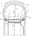
図1に示すように、本発明の車両の車輪構造は、ホイール1と、ホイール1のリム2に装着されるタイヤ3と、タイヤ3とリム2により囲繞されるタイヤ空気室4と、タイヤ空気室4と対向配備したダンパ部材6を備える。
ダンパ部材6はホイール1のリム2に外嵌支持される共にホイール半径方向に所定厚さの環状主部5を有する。このダンパ部材6は、次の3つの機能部の内の少なくとも2つの機能部を有するよう形成される。
Hereinafter, embodiments of the present invention will be described with reference to the drawings.
Here, the whole structure of the wheel structure of the vehicle of this invention is demonstrated.
As shown in FIG. 1, the vehicle wheel structure of the present invention includes a wheel 1, a tire 3 attached to a rim 2 of the wheel 1, a tire air chamber 4 surrounded by the tire 3 and the rim 2, and tire air. A damper member 6 disposed opposite to the chamber 4 is provided.
The damper member 6 is externally supported by the rim 2 of the wheel 1 and has an annular main portion 5 having a predetermined thickness in the wheel radial direction. The damper member 6 is formed so as to have at least two functional parts among the following three functional parts.

1の機能部は環状主部5の内部にタイヤ空気室4の音圧を下げる共鳴室7の機能が得られる共鳴器8である。2の機能部は環状主部5の周方向に区分された複数の慣性体(突状膨出部)9により動吸振機能が得られる動吸振器11である。3の機能部は環状主部5で形成されタイヤ空気室4の閉断面の空間幅tdを狭める膨出部121により気柱共鳴周波数の切換えによる消音機能が得られる気柱共鳴減衰部12である。
このようなダンパ部材6は、路面からタイヤ空気室に達する騒音の音圧を下げる共鳴室の機能と、タイヤ空気室の騒音や駆動側からの回転変動に起因するホイール振動が大きい周方向領域部を慣性体(突状膨出部)9にしてホイール振動を減衰する動吸振機能が得られる動吸振器(ダイナミックダンパ)の機能と、タイヤ空気室4の閉断面の空間幅tdを狭める複数の膨出部121により気柱共鳴周波数を切換え消音機能を得る気柱共鳴減衰部の機能と、の内の少なくとも2つを有する。これにより、ダンパ部材6のみの装着により、複数の車室内騒音要因を減衰するよう構成される。
1 is a resonator 8 in which the function of the resonance chamber 7 for lowering the sound pressure of the tire air chamber 4 is obtained inside the annular main portion 5. The functional part 2 is a dynamic vibration absorber 11 that can obtain a dynamic vibration absorbing function by a plurality of inertia bodies (protruding bulged portions) 9 divided in the circumferential direction of the annular main portion 5. The functional part 3 is an air column resonance attenuating part 12 which is formed by the annular main part 5 and can obtain a silencing function by switching the air column resonance frequency by the bulging part 121 which narrows the space width td of the closed cross section of the tire air chamber 4. .
Such a damper member 6 has a function of a resonance chamber that lowers the sound pressure of noise reaching the tire air chamber from the road surface, and a circumferential region portion where wheel vibration caused by noise in the tire air chamber and rotational fluctuation from the drive side is large. The inertial body (protruding bulging portion) 9 serves as a dynamic vibration absorber (dynamic damper) for obtaining a dynamic vibration damping function for attenuating wheel vibration, and a plurality of widths td of the closed cross section of the tire air chamber 4 are reduced. It has at least two of the functions of the air column resonance attenuating unit that obtains the silencing function by switching the air column resonance frequency by the bulging portion 121. Thereby, it is comprised so that a several vehicle interior noise factor may be attenuate | damped by mounting | wearing only with the damper member 6. FIG.

次に、本発明の第1実施形態(請求項1,2相当)を、図2〜4に沿って説明する。
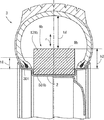
本発明の第1実施形態の車両の車輪構造は、ホイール1とそのリム2に装着されるチューブレス空気圧タイヤ3と、タイヤ3とリム2により囲繞されるタイヤ空気室4と、タイヤ空気室4と対向しホイール1のリム2に外嵌され、接着されるホイールダンパであるダンパ部材6を備える。
図2、図4に示すように、ホイール1は、ディスク15と、ディスク15の外周に一体結合されたリム2と、リム2の端縁部のリムフランジ201とを備えた環状体を成す。ディスク15とリム2は鋼、アルミニウム合金等で形成される。タイヤ空気室4に加圧空気を充填するため、不図示のバルブがホイール1の適所に設けられる。リム2には両端のリムフランジ201を用いてタイヤ3のビード部301を係合支持する。タイヤ3はトレッド部302、サイドウォール部303、ビード部301を有する。
Next, a first embodiment of the present invention (corresponding to claims 1 and 2) will be described with reference to FIGS.
The wheel structure of the vehicle according to the first embodiment of the present invention includes a tubeless pneumatic tire 3 attached to the wheel 1 and its rim 2, a tire air chamber 4 surrounded by the tire 3 and the rim 2, and a tire air chamber 4. A damper member 6 that is a wheel damper that is externally fitted to and bonded to the rim 2 of the wheel 1 is provided.
As shown in FIGS. 2 and 4, the wheel 1 forms an annular body including a disk 15, a rim 2 integrally coupled to the outer periphery of the disk 15, and a rim flange 201 at an end edge of the rim 2. The disk 15 and the rim 2 are made of steel, aluminum alloy or the like. In order to fill the tire air chamber 4 with pressurized air, a valve (not shown) is provided at an appropriate position of the wheel 1. The rim 2 engages and supports the bead portion 301 of the tire 3 using rim flanges 201 at both ends. The tire 3 has a tread portion 302, a sidewall portion 303, and a bead portion 301.

ダンパ部材6は、例えば、合成ゴム等からなるホイール半径方向rに所定厚さの環状主部5を有する。この環状主部5はホイール1のリム2の幅方向でほぼ中央に外嵌される。このリム2の外周面には回転中心側に凹む環状凹部202が環状に一体形成され、同環状凹部202に環状主部5が圧入される。
ここでのダンパ部材6はタイヤ空気室4の音圧を下げる共鳴器8としての機能部とホイールの動吸振機能(制振機能)が得られる動吸振器11としての2つの両機能部(図1参照)を一体的に形成した構成を採る。
ここで共鳴器8は、図3に破線で示すように、環状主部5の内周側環状層を周方向に複数(ここでは4つ)に区分けされ、各区分けされた共鳴室7,7、・・にはそれぞれ開口mが形成され、共鳴箱の構造を成している。共鳴室7の周方向長さである室周長Lsはタイヤ空気室4の音圧低減機能が高まるようにチューニングされる。
一方、動吸振器11は環状主部5の外周側環状層に複数(ここでは4つ)形成される。これら周方向に所定長さの隙間tcを挟んで互いに区分された4つの慣性体を成す突状膨出部9により制振機能が得られる構成を成している。突状膨出部9の周方向長さである突周長Ltはホイール1の制振機能が高まる長さにチューニングされる。
このような第1実施形態の車両の車輪構造を適用した車輪は車両の走行時において、路面反力をタイヤ3よりホイール1で受けてホイール振動を発生し、これに起因するロードノイズが発生する。
The damper member 6 includes, for example, an annular main portion 5 having a predetermined thickness in the wheel radial direction r made of synthetic rubber or the like. The annular main portion 5 is fitted around the center of the rim 2 of the wheel 1 in the width direction. An annular recess 202 that is recessed toward the center of rotation is integrally formed on the outer peripheral surface of the rim 2, and the annular main portion 5 is press-fitted into the annular recess 202.
The damper member 6 here includes a functional part as a resonator 8 that lowers the sound pressure in the tire air chamber 4 and two functional parts as a dynamic vibration absorber 11 that provides a dynamic vibration absorbing function (vibration damping function) of the wheel (see FIG. 1) is integrally formed.
Here, as shown by a broken line in FIG. 3, the resonator 8 is divided into a plurality (here, four) of the inner peripheral annular layer of the annular main portion 5 in the circumferential direction, and the divided resonance chambers 7, 7 are divided. ,... Are each formed with an opening m to form a resonance box structure. The chamber circumferential length Ls that is the circumferential length of the resonance chamber 7 is tuned so that the sound pressure reducing function of the tire air chamber 4 is enhanced.
On the other hand, a plurality (four in this case) of the dynamic vibration absorbers 11 are formed in the outer circumferential side annular layer of the annular main portion 5. A vibration damping function is obtained by the projecting bulging portions 9 forming four inertia bodies separated from each other with a gap tc having a predetermined length in the circumferential direction. The projecting circumferential length Lt, which is the circumferential length of the projecting bulging portion 9, is tuned to such a length that the vibration damping function of the wheel 1 is enhanced.
The wheel to which the wheel structure of the vehicle according to the first embodiment is applied receives a road surface reaction force from the tire 3 by the wheel 1 when the vehicle travels, and generates wheel vibration, resulting in road noise. .

更に、タイヤ空気室4には車輪回転時のタイヤ変形部の回転変位に伴い気柱共鳴音が生じる。このタイヤ空気室4の気柱共鳴音はホイール2にホイール振動を生じさせ、ロードノイズを発生する。
更に、駆動系からの回転変動もホイール1に入力する。
この場合、路面からの振動入力がホイール1でホイール振動を発生するが、これを減衰させるように動吸振器11の突周長Ltを調整する。この動吸振器11の減衰特性が高まるように突周長Ltをチューニングすることで、図12に符合E2で示すように、ホイール振動起因のロードノイズである車内音を減衰できる。
更に、ホイール1が受ける駆動系の回転変動は動吸振器11の内の突周長Ltのチューニングが合うものにより減衰し、図12に符合E1で示すように、回転変動起因のこもり音である車内音を減衰できる。
Furthermore, air column resonance is generated in the tire air chamber 4 due to the rotational displacement of the tire deformation portion when the wheel rotates. The air column resonance sound of the tire air chamber 4 causes the wheel 2 to vibrate and generate road noise.
Furthermore, rotational fluctuations from the drive system are also input to the wheel 1.
In this case, the vibration input from the road surface generates wheel vibration in the wheel 1, and the projecting circumferential length Lt of the dynamic vibration absorber 11 is adjusted so as to attenuate it. By tuning the projecting circumference Lt so that the damping characteristic of the dynamic vibration absorber 11 is enhanced, as shown by the symbol E2 in FIG. 12, the in-vehicle sound that is road noise caused by wheel vibration can be attenuated.
Further, the rotational fluctuation of the drive system received by the wheel 1 is attenuated by the one that matches the tuning of the projecting circumferential length Lt in the dynamic vibration absorber 11, and is a humming noise caused by the rotational fluctuation as indicated by reference numeral E1 in FIG. Attenuates the interior sound.

更に、タイヤ空気室4に生じる気柱共鳴音を共鳴器8の中で共鳴室7の室周長Lsのチューニングが合うものにより減衰し、図12に符合E3で示すように、気柱共鳴音起因のロードノイズである車内音を減衰できる。
このように、単一のダンパ部材6をホイール1のリム2に装着することで、第1実施形態の車両の車輪構造を適用した車輪は走行時のホイール振動起因の車内音、回転変動起因の車内音、気柱共鳴音起因の車内音を減衰できる。しかも、ダンパ部材6をリム2に外嵌氏接着する作業性が良く、取り付けスペースの確保も単一のダンパ部材6を取り付けるのみで済み、装着性も良い。
Further, the air column resonance generated in the tire air chamber 4 is attenuated by the resonator 8 that matches the tuning of the chamber circumferential length Ls of the resonance chamber 7, and as shown by reference numeral E3 in FIG. It can attenuate the interior noise that is the road noise.
As described above, by mounting the single damper member 6 on the rim 2 of the wheel 1, the wheel to which the wheel structure of the vehicle according to the first embodiment is applied is caused by in-vehicle sound caused by wheel vibration during traveling and caused by rotational fluctuation. Car interior sound and car interior sound caused by air column resonance can be attenuated. In addition, the workability of attaching the damper member 6 to the rim 2 is good, the mounting space is secured only by attaching the single damper member 6, and the wearability is also good.

上述のところで、単一のダンパ部材6をホイール1のリム2に外嵌させ、接着していたが、これに代えて、図5に示すように、リム2の外周面に断面略U字形でリング状のダンパブラケット17を溶着し、ダンパブラケット17にダンパ部材6aを圧入嵌着してもよい。
このダンパブラケット17はその底部171がリム2に接着し、左右縦フランジ172がダンパ部材6aを圧入嵌着可能な幅に形成される。しかも、左右縦フランジ172の開口端には内向き突部173が形成され、これによりダンパ部材6aの左右側壁を挟圧し、離脱を防止している。場合により、ダンパ部材6aの左右側壁側に内向き突部173と嵌合する凹溝g(2点差線参照)を形成してもよい。
この場合も図1のダンパ部材6と同様の作用効果を発揮でき、ダンパ部材6の支持を安定させることできる。
As described above, the single damper member 6 is externally fitted to the rim 2 of the wheel 1 and bonded thereto. Instead, as shown in FIG. 5, the outer peripheral surface of the rim 2 has a substantially U-shaped cross section. The ring-shaped damper bracket 17 may be welded, and the damper member 6a may be press-fit into the damper bracket 17.
The damper bracket 17 has a bottom 171 bonded to the rim 2 and left and right vertical flanges 172 formed to have a width that allows the damper member 6a to be press-fit. In addition, inward protrusions 173 are formed at the open ends of the left and right vertical flanges 172, thereby clamping the left and right side walls of the damper member 6a to prevent detachment. Depending on circumstances, a concave groove g (see a two-dot chain line) that fits the inwardly protruding portion 173 may be formed on the left and right side walls of the damper member 6a.
Also in this case, the same effect as the damper member 6 of FIG. 1 can be exhibited, and the support of the damper member 6 can be stabilized.

上述のところで、動吸振器11は環状主部5の外周側環状層に形成され、周方向に所定長さの隙間tcを挟んで互いに区分された複数(ここでは4つ)の慣性体を成す突状膨出部9により制振機能が得られる構成を成している。これに代えて、図13に示すように、環状主部5の内周側環状基層部505の外側の外周側環状層部506内に周方向に沿って複数の慣性体である金属片Fを順次配設して動吸振器11’構成してもよい。この場合、慣性体である金属片Fの形状(周方向長さ、厚さ、幅)や数や相対間隔等を調整することで、ホイール1が受ける駆動系の回転変動やホイール振動を抑制して減衰機能を調整し、回転変動起因のこもり音である車内音やホイール振動起因のロードノイズを減衰できる。特に環状主部5の外周面がフラット化し、装着性が向上する。
次に、本発明の第2実施形態(請求項3相当)を、図6、7に沿って説明する。
なお、本発明の第2実施形態の車両の車輪構造は、第1実施形態と対比し、ダンパ部材6bの機能部構成が相違するのみであり、同一部材の重複する説明を略す。
第2実施形態のダンパ部材6bは、ホイールの制振機能が得られる動吸振器11bとしての機能部と、気柱共鳴周波数を切換え消音機能を得る気柱共鳴減衰部12bとしての機能部(図1参照)を一体的に形成した構成を採る。
動吸振器11bは環状主部5の内周側環状基層部501bの外側に形成され、周方向に所定長さの隙間tcbを挟んで互いに区分された複数(ここでは2つ)の突状膨出部9bにより制振機能が得られる構成を成している。突状膨出部9bの周方向長さである突周長Ltbはホイール1の制振機能が高まるようにチューニングされる。
As described above, the dynamic vibration absorber 11 is formed in the annular layer on the outer peripheral side of the annular main portion 5 and forms a plurality of (four in this case) inertial bodies that are separated from each other with a gap tc having a predetermined length in the circumferential direction. The projecting bulging portion 9 is configured to obtain a damping function. Instead, as shown in FIG. 13, a plurality of metal pieces F, which are inertial bodies, are provided along the circumferential direction in the outer peripheral side annular layer portion 506 outside the inner peripheral side annular base layer portion 505 of the annular main portion 5. The dynamic vibration absorber 11 ′ may be configured by sequentially arranging. In this case, by adjusting the shape (circumferential length, thickness, width), number, relative spacing, etc. of the metal piece F, which is an inertial body, the rotational fluctuation and wheel vibration of the drive system received by the wheel 1 are suppressed. By adjusting the damping function, it is possible to attenuate the in-vehicle sound, which is a loud noise caused by rotational fluctuations, and road noise, which is caused by wheel vibration. In particular, the outer peripheral surface of the annular main portion 5 is flattened, and the mountability is improved.
Next, a second embodiment of the present invention (corresponding to claim 3) will be described with reference to FIGS.
The vehicle wheel structure according to the second embodiment of the present invention is different from the first embodiment only in the functional part configuration of the damper member 6b, and the description of the same members is omitted.
The damper member 6b of the second embodiment includes a functional part as a dynamic vibration absorber 11b that obtains a wheel damping function, and a functional part as an air column resonance attenuating part 12b that obtains a silencing function by switching the air column resonance frequency (see FIG. 1) is integrally formed.
The dynamic vibration absorber 11b is formed on the outer side of the inner peripheral side annular base layer portion 501b of the annular main portion 5, and has a plurality (two in this case) of protruding bulges separated from each other with a gap tcb having a predetermined length in the circumferential direction. The output portion 9b is configured to obtain a vibration control function. The projecting circumferential length Ltb, which is the circumferential length of the projecting bulging portion 9b, is tuned so that the vibration damping function of the wheel 1 is enhanced.

一方、気柱共鳴減衰部12bは環状主部5の内周側環状基層部501b(図6参照)の外側に周方向に2箇所、互いに中心点0を挟んで対向する膨出部121bを形成した構成を採る。
2箇所の膨出部121bは内周側環状基層部501bの外側に形成されている2箇所の突状膨出部9bとは互いの中心線が交差する方向に配設され、相互の干渉を防止している。
気柱共鳴減衰部12bの膨出部121bはタイヤ空気室4の閉断面の空間幅td(図7参照)を所定量狭める(絞る)ことで、気柱共鳴周波数を切換え消音機能を得るよう、その狭める空間幅tdのチューニングが成される。
On the other hand, the air column resonance attenuating portion 12b forms two bulging portions 121b facing each other across the center point 0 on the outer peripheral side annular base layer portion 501b (see FIG. 6) of the annular main portion 5 in the circumferential direction. Adopted the configuration.
The two bulging portions 121b are arranged in a direction in which the center lines intersect with the two protruding bulging portions 9b formed on the outer side of the inner circumferential side annular base layer portion 501b, thereby preventing mutual interference. It is preventing.
The bulging part 121b of the air column resonance attenuating part 12b narrows (squeezes) the space width td (see FIG. 7) of the closed cross section of the tire air chamber 4 by a predetermined amount so as to obtain a silencing function by switching the air column resonance frequency. The narrowing space width td is tuned.

このような第2実施形態の車両の車輪構造を適用した車輪は車両の走行時において、路面反力をタイヤ3よりホイール1で受けてホイールが振動し、ホイール振動に起因するロードノイズが発生する。更に、タイヤ空気室4には車輪回転時のタイヤ3変形による気柱共鳴音が生じ、この気柱共鳴音がホイール1にホイール振動を生じさせ、ロードノイズを発生する。更に、駆動系からの回転変動もホイール1に入力する。
この場合、路面からの振動入力がホイール1でホイール振動を発生するがこれを動吸振器11bの内の突周長Ltbのチューニングを合わせて減衰し、図12に符合E2で示すホイール振動起因のロードノイズである車内音を減衰する。しかも、駆動系の回転変動は動吸振器11bの内の突周長Ltbのチューニングが合うものにより減衰し、図12に符合E1で示す回転変動起因のこもり音である車内音を減衰する。
The wheel to which the wheel structure of the vehicle according to the second embodiment is applied receives road reaction force from the tire 3 by the wheel 1 when the vehicle travels, and the wheel vibrates, and road noise caused by the wheel vibration is generated. . Further, an air column resonance sound is generated in the tire air chamber 4 due to deformation of the tire 3 when the wheel rotates, and this air column resonance sound causes the wheel 1 to vibrate and generates road noise. Furthermore, rotational fluctuations from the drive system are also input to the wheel 1.
In this case, the vibration input from the road surface generates wheel vibration in the wheel 1, which is attenuated by tuning the projecting circumferential length Ltb in the dynamic vibration absorber 11b, and is caused by the wheel vibration indicated by reference numeral E2 in FIG. Attenuates road noise, which is road noise. In addition, the rotational fluctuation of the drive system is attenuated by the adjustment of the projecting circumferential length Ltb in the dynamic vibration absorber 11b, and the in-vehicle sound, which is a booming noise caused by the rotational fluctuation, indicated by reference numeral E1 in FIG.

更に、一対の膨出部121によりタイヤ空気室4の閉断面の空間幅td(タイヤ半径方向の空間幅)を他の部位より狭める(絞る)ことで、タイヤ空気室4に生じる気柱共鳴音の気柱共鳴周波数を切換え、消音機能を得るよう、その狭める空間幅tdのチューニングが成される。これにより、図12に符合E3で示す、気柱共鳴音起因のロードノイズである車内音を減衰できる。
このように、単一のダンパ部材6をホイール1のリム2に装着することで、第2実施形態の車両の車輪構造を適用した車輪は走行時のホイール振動起因の車内音、回転変動起因の車内音、気柱共鳴音起因の車内音を減衰できる。
Further, the air column resonance sound generated in the tire air chamber 4 by narrowing (squeezing) the space width td (space width in the tire radial direction) of the closed cross section of the tire air chamber 4 from the other portion by the pair of bulging portions 121. The narrowing space width td is tuned so as to switch the air column resonance frequency and obtain a silencing function. Thereby, the vehicle interior sound, which is road noise caused by the air column resonance sound, indicated by reference numeral E3 in FIG. 12, can be attenuated.
Thus, by mounting the single damper member 6 on the rim 2 of the wheel 1, the wheel to which the wheel structure of the vehicle of the second embodiment is applied is caused by in-vehicle noise caused by wheel vibration during traveling and caused by rotational fluctuation. Car interior sound and car interior sound caused by air column resonance can be attenuated.

次に、本発明の第3実施形態(請求項4相当)を、図8、9に沿って説明する。
なお、本発明の第3実施形態の車両の車輪構造は、第1実施形態と対比し、ダンパ部材6cの機能部構成が相違するのみであり、同一部材の重複する説明を略す。
第3実施形態のダンパ部材6cは、タイヤ空気室4の音圧を下げる共鳴器8cとしての機能部と、気柱共鳴周波数を切換え消音機能を得る気柱共鳴減衰部12cとしての機能部(図1参照)を一体的に形成した構成を採る。
ここで共鳴器8は環状主部5の内周側環状層を周方向に複数(ここでは2つ)に区分けし、各区分けされた共鳴室7c,7cにはそれぞれ開口mが形成され、共鳴箱の構造を成している。共鳴室7cの周方向長さである室周長Lsはタイヤ空気室4の音圧低減機能が高まるようにチューニングされる。
Next, a third embodiment of the present invention (corresponding to claim 4) will be described with reference to FIGS.
Note that the vehicle wheel structure of the third embodiment of the present invention is different from the first embodiment only in the functional part configuration of the damper member 6c, and the description of the same members is omitted.
The damper member 6c of the third embodiment includes a functional unit as a resonator 8c that lowers the sound pressure of the tire air chamber 4, and a functional unit as an air column resonance attenuation unit 12c that switches the air column resonance frequency to obtain a silencing function (see FIG. 1) is integrally formed.
Here, the resonator 8 divides the inner circumferential side annular layer of the annular main portion 5 into a plurality (in this case, two) in the circumferential direction, and openings m are formed in the divided resonance chambers 7c and 7c, respectively. It has a box structure. The chamber circumferential length Ls, which is the circumferential length of the resonance chamber 7c, is tuned so that the sound pressure reducing function of the tire air chamber 4 is enhanced.

一方、気柱共鳴減衰部12cは環状主部5の内周側環状層501c(図8参照)の外側に周方向に2箇所(図9参照)、互いに中心点0を挟んで対向する膨出部121cを形成した構成を採る。
2箇所の膨出部121cは内周側環状層501cの共鳴室7c,7cの開口mとは相互の干渉がないように配設されている。
このような第3実施形態の車両の車輪構造を適用した車輪は車両の走行時において、
、路面反力をタイヤ3よりホイール1で受けてホイールが振動し、ホイール振動に起因するロードノイズが発生する。更に、タイヤ空気室4には車輪回転時のタイヤ3の変形による気柱共鳴音が生じ、この気柱共鳴音がホイール1にホイール振動を生じさせ、ロードノイズを発生する。更に、駆動系からの回転変動もホイール1に入力する。
この場合、タイヤ空気室4に生じる気柱共鳴音を共鳴室7cの室周長Lsのチューニングが合うものにより減衰させる。これにより、図12に符合E3で示すように、気柱共鳴音起因のロードノイズである車内音を減衰できる。しかも、駆動系の回転変動は動吸振器でもある気柱共鳴減衰部12cのチューニングが合うものにより減衰し、図12に符合E1で示す回転変動起因のこもり音である車内音を減衰する。
On the other hand, the air column resonance attenuating portion 12c has two bulges (see FIG. 9) in the circumferential direction on the outer side of the inner peripheral annular layer 501c (see FIG. 8) of the annular main portion 5 and facing each other with the center point 0 therebetween. A configuration in which the part 121c is formed is adopted.
The two bulging portions 121c are disposed so as not to interfere with the openings m of the resonance chambers 7c and 7c of the inner peripheral annular layer 501c.
The wheel to which the wheel structure of the vehicle according to the third embodiment is applied is when the vehicle is running.
The road surface reaction force is received by the wheel 1 from the tire 3 and the wheel vibrates, and road noise due to the wheel vibration is generated. Further, air column resonance sound is generated in the tire air chamber 4 due to deformation of the tire 3 when the wheel rotates, and this air column resonance sound causes wheel vibration in the wheel 1 to generate road noise. Furthermore, rotational fluctuations from the drive system are also input to the wheel 1.
In this case, the air column resonance generated in the tire air chamber 4 is attenuated by the one that matches the tuning of the chamber circumferential length Ls of the resonance chamber 7c. Thereby, as indicated by reference numeral E3 in FIG. 12, the vehicle interior sound, which is road noise caused by the air column resonance, can be attenuated. In addition, the rotational fluctuation of the drive system is attenuated by the tuning of the air column resonance attenuating section 12c, which is also a dynamic vibration absorber, and the in-vehicle sound, which is a booming noise caused by the rotational fluctuation, indicated by reference numeral E1 in FIG.

更に、一対の膨出部121によりタイヤ空気室4の閉断面の空間幅tdcを狭める(絞る)ことで、タイヤ空気室4に生じる気柱共鳴音の気柱共鳴周波数を切換え、消音機能を得るよう、その狭める空間幅tdのチューニングが成される。これにより、図12に符合E3で示す、気柱共鳴音起因のロードノイズである車内音を減衰できる。
このように、単一のダンパ部材6cをホイール1のリム2に装着することで、第3実施形態の車両の車輪構造を適用した車輪は走行時のホイール振動起因の車内音、回転変動起因の車内音、気柱共鳴音起因の車内音を減衰できる。
Furthermore, by narrowing (squeezing) the space width tdc of the closed cross section of the tire air chamber 4 by the pair of bulging portions 121, the air column resonance frequency of the air column resonance generated in the tire air chamber 4 is switched to obtain a silencing function. Thus, tuning of the narrowing space width td is performed. Thereby, the vehicle interior sound, which is road noise caused by the air column resonance sound, indicated by reference numeral E3 in FIG. 12, can be attenuated.
As described above, by mounting the single damper member 6c on the rim 2 of the wheel 1, the wheel to which the wheel structure of the vehicle of the third embodiment is applied is caused by the in-vehicle sound caused by wheel vibration at the time of traveling and the rotation fluctuation caused. Car interior sound and car interior sound caused by air column resonance can be attenuated.

次に、本発明の第4実施形態(請求項5相当)を、図10、11に沿って説明する。
なお、本発明の第4実施形態の車両の車輪構造は、第1実施形態と対比し、ダンパ部材6dの機能部構成が相違するのみであり、同一部材の重複する説明を略す。
第4実施形態のダンパ部材6dは、タイヤ空気室4の音圧を下げる共鳴室7dを有する共鳴器8dとしての機能部と、ホイールの制振機能が得られる動吸振器11dとしての機能部と、気柱共鳴周波数を切換え消音機能を得る気柱共鳴減衰部12dとしての機能部(図1参照)の3つの機能部を一体的に形成した構成を採る。
なお、これら3つの機能部は第1〜第3実施形態で説明したと同様構成であり、重複説明を略す。
Next, a fourth embodiment (corresponding to claim 5) of the present invention will be described with reference to FIGS.
The vehicle wheel structure of the fourth embodiment of the present invention is different from the first embodiment only in the functional part configuration of the damper member 6d, and the description of the same members is omitted.
The damper member 6d of the fourth embodiment includes a functional part as a resonator 8d having a resonance chamber 7d for lowering the sound pressure of the tire air chamber 4, and a functional part as a dynamic vibration absorber 11d capable of obtaining a vibration damping function of the wheel. Then, a configuration is adopted in which three functional parts of the functional part (see FIG. 1) as the air column resonance attenuating part 12d for switching the air column resonance frequency to obtain a silencing function are integrally formed.
Note that these three functional units have the same configuration as described in the first to third embodiments, and redundant description is omitted.

このような第4実施形態の車両の車輪構造を適用した車輪は車両の走行時において、路面反力をタイヤ3よりホイール1で受けてホイールが振動し、ホイール振動に起因するロードノイズが発生する。更に、タイヤ空気室4には車輪回転時のタイヤ3変形による気柱共鳴音が生じ、この気柱共鳴音がホイール1にホイール振動を生じさせ、ロードノイズを発生する。更に、駆動系からの回転変動もホイール1に入力する。
この第4実施形態の車両の車輪構造の場合、第1〜第3実施形態で説明したと同様の3つの共鳴器8と、動吸振器11と、気柱共鳴減衰部12とが全て働く。
このように、単一のダンパ部材6dをホイール1のリム2に外嵌状に装着することで、第4実施形態の車両の車輪構造を適用した車輪は走行時のホイール振動起因の車内音、回転変動起因の車内音、気柱共鳴音起因の車内音を確実に減衰できる。
A wheel to which the wheel structure of the vehicle according to the fourth embodiment is applied receives road reaction force from the tire 3 by the wheel 1 when the vehicle travels, and the wheel vibrates, and road noise caused by the wheel vibration is generated. . Further, an air column resonance sound is generated in the tire air chamber 4 due to deformation of the tire 3 when the wheel rotates, and this air column resonance sound causes the wheel 1 to vibrate and generates road noise. Furthermore, rotational fluctuations from the drive system are also input to the wheel 1.
In the case of the vehicle wheel structure of the fourth embodiment, the three resonators 8, the dynamic vibration absorber 11, and the air column resonance attenuator 12 similar to those described in the first to third embodiments work.
As described above, by mounting the single damper member 6d on the rim 2 of the wheel 1 so as to be fitted externally, the wheel to which the wheel structure of the vehicle according to the fourth embodiment is applied causes the vehicle interior noise caused by the wheel vibration during traveling, In-vehicle sound caused by rotational fluctuations and in-vehicle sound caused by air column resonance can be reliably attenuated.

以上、本発明の実施形態を説明したが、本発明は係る実施形態に限定されるものではなく、本発明の趣旨を逸脱しない範囲で種々変形して実施することができる。   Although the embodiment of the present invention has been described above, the present invention is not limited to the embodiment, and various modifications can be made without departing from the spirit of the present invention.

1 ホイール
2 リム
3 タイヤ
4 タイヤ空気室
5 環状主部
6 ダンパ部材
7 共鳴室
8 共鳴器
9 突状膨出部(慣性体)
11 動吸振器
12 気柱共鳴減衰部
121 膨出部
r ホイール半径方向
F 金属片(慣性体)
DESCRIPTION OF SYMBOLS 1 Wheel 2 Rim 3 Tire 4 Tire air chamber 5 Annular main part 6 Damper member 7 Resonance chamber 8 Resonator 9 Protruding bulge part (inertial body)
DESCRIPTION OF SYMBOLS 11 Dynamic vibration absorber 12 Air column resonance attenuation part 121 Swelling part r Wheel radial direction F Metal piece (inertial body)

Claims (7)

ホイールと該ホイールのリムに装着されたタイヤと該タイヤとリムにより囲繞されるタイヤ空気室とを形成した車両の車輪構造において、
前記タイヤ空気室と対向し前記ホイールのリムに外嵌支持されると共にホイール半径方向に所定厚さの環状主部を有したダンパ部材を備え、
前記ダンパ部材は、
前記環状主部の内部に設けられ前記タイヤ空気室の音圧を下げる共鳴室の機能が得られる共鳴器と、前記環状主部に形成され周方向に区分された複数の突状膨出部により動吸振機能が得られる動吸振器と、前記環状主部に形成され前記タイヤ空気室の閉断面の空間幅を狭める膨出部により気柱共鳴周波数を切換え消音機能を得る気柱共鳴減衰部と、の内の少なくとも2つの機能部を有するよう形成された、
ことを特徴とする車両の車輪構造。
In a vehicle wheel structure in which a wheel, a tire mounted on a rim of the wheel, and a tire air chamber surrounded by the tire and the rim are formed,
A damper member facing the tire air chamber and externally supported by the wheel rim and having an annular main portion with a predetermined thickness in the wheel radial direction;
The damper member is
A resonator provided inside the annular main portion and capable of obtaining a function of a resonance chamber that lowers the sound pressure of the tire air chamber, and a plurality of protruding bulge portions formed in the annular main portion and divided in the circumferential direction A dynamic vibration absorber capable of obtaining a dynamic vibration absorption function, and an air column resonance attenuation unit which obtains a silencing function by switching an air column resonance frequency by a bulging portion formed in the annular main portion and narrowing the space width of the closed section of the tire air chamber. , Formed to have at least two functional parts of
A vehicle wheel structure characterized by that.
前記ダンパ部材は、前記共鳴器と前記動吸振器との両機能部を有するよう形成された、
ことを特徴とする請求項1記載の車両の車輪構造。
The damper member is formed to have both functional parts of the resonator and the dynamic vibration absorber,
The vehicle wheel structure according to claim 1, wherein:
前記ダンパ部材は、前記動吸振器と前記気柱共鳴減衰部との両機能部を有するよう形成された、ことを特徴とする請求項1記載の車両の車輪構造。   2. The vehicle wheel structure according to claim 1, wherein the damper member is formed to have both functional parts of the dynamic vibration absorber and the air column resonance attenuation part. 3. 前記ダンパ部材は、前記共鳴器と前記気柱共鳴減衰部との両機能部を有するよう形成された、ことを特徴とする請求項1記載の車両の車輪構造。   2. The vehicle wheel structure according to claim 1, wherein the damper member is formed so as to have both functional parts of the resonator and the air column resonance attenuating part. 前記ダンパ部材は、前記共鳴器と前記動吸振器と前記気柱共鳴減衰部との3つの機能部を有するよう形成された、ことを特徴とする請求項1記載の車両の車輪構造。   2. The vehicle wheel structure according to claim 1, wherein the damper member is formed to have three functional parts of the resonator, the dynamic vibration absorber, and the air column resonance attenuation part. 3. 前記ダンパ部材は前記ホイールのリムに外嵌され接着される、ことを特徴とする請求項1〜5のいずれか一つに記載の車両の車輪構造。   The vehicle wheel structure according to any one of claims 1 to 5, wherein the damper member is externally fitted and bonded to a rim of the wheel. 前記ダンパ部材の環状主部が前記ホイールのリムに一体形成の環状凹部に圧入される、ことを特徴とする請求項1〜5のいずれか一つに記載の車両の車輪構造。   The vehicle wheel structure according to any one of claims 1 to 5, wherein an annular main portion of the damper member is press-fitted into an annular recess integrally formed with the rim of the wheel.
JP2013078928A 2013-04-04 2013-04-04 Vehicular wheel structure Pending JP2014201205A (en)

Priority Applications (1)

Application Number Priority Date Filing Date Title
JP2013078928A JP2014201205A (en) 2013-04-04 2013-04-04 Vehicular wheel structure

Applications Claiming Priority (1)

Application Number Priority Date Filing Date Title
JP2013078928A JP2014201205A (en) 2013-04-04 2013-04-04 Vehicular wheel structure

Publications (1)

Publication Number Publication Date
JP2014201205A true JP2014201205A (en) 2014-10-27

Family

ID=52352036

Family Applications (1)

Application Number Title Priority Date Filing Date
JP2013078928A Pending JP2014201205A (en) 2013-04-04 2013-04-04 Vehicular wheel structure

Country Status (1)

Country Link
JP (1) JP2014201205A (en)

Cited By (8)

* Cited by examiner, † Cited by third party
Publication number Priority date Publication date Assignee Title
KR101822273B1 (en) 2016-04-18 2018-03-09 현대자동차주식회사 Apparatus for noise diminution of tire
CN110239276A (en) * 2018-03-09 2019-09-17 本田技研工业株式会社 Wheel for vehicle hub
CN110481241A (en) * 2018-05-14 2019-11-22 本田技研工业株式会社 Wheel for vehicle hub and its manufacturing method
EP3202835B1 (en) 2014-09-30 2020-10-28 Sekisui Plastics Co., Ltd. Amide elastomer foam particles, method for producing same, foam molded body and method for producing foam molded body
KR20210047384A (en) * 2019-10-21 2021-04-30 현대성우캐스팅(주) Vehicle wheel equipped with sound absorbing module of porous structure
KR20210047385A (en) * 2019-10-21 2021-04-30 현대성우캐스팅(주) Vehicle wheels including a housing having a sound absorbing module having a porous structure
KR20220004873A (en) * 2020-07-03 2022-01-12 현대성우캐스팅(주) Vehicle wheels including a housing having a sound absorbing module having a porous structure
US11584159B2 (en) * 2018-04-02 2023-02-21 Honda Motor Co., Ltd. Vehicle wheel and Helmholtz resonator

Citations (4)

* Cited by examiner, † Cited by third party
Publication number Priority date Publication date Assignee Title
JPH03107302U (en) * 1990-02-20 1991-11-05
JP2001113902A (en) * 1999-10-15 2001-04-24 Mitsubishi Motors Corp Wheel structure for vehicle
JP2004090727A (en) * 2002-08-30 2004-03-25 Tokai Rubber Ind Ltd Wheel damping device
JP2004306760A (en) * 2003-04-07 2004-11-04 Honda Motor Co Ltd Resonance preventing belt for wheel

Patent Citations (4)

* Cited by examiner, † Cited by third party
Publication number Priority date Publication date Assignee Title
JPH03107302U (en) * 1990-02-20 1991-11-05
JP2001113902A (en) * 1999-10-15 2001-04-24 Mitsubishi Motors Corp Wheel structure for vehicle
JP2004090727A (en) * 2002-08-30 2004-03-25 Tokai Rubber Ind Ltd Wheel damping device
JP2004306760A (en) * 2003-04-07 2004-11-04 Honda Motor Co Ltd Resonance preventing belt for wheel

Cited By (14)

* Cited by examiner, † Cited by third party
Publication number Priority date Publication date Assignee Title
EP3202835B1 (en) 2014-09-30 2020-10-28 Sekisui Plastics Co., Ltd. Amide elastomer foam particles, method for producing same, foam molded body and method for producing foam molded body
KR101822273B1 (en) 2016-04-18 2018-03-09 현대자동차주식회사 Apparatus for noise diminution of tire
JP7045885B2 (en) 2018-03-09 2022-04-01 本田技研工業株式会社 Vehicle wheels
CN110239276A (en) * 2018-03-09 2019-09-17 本田技研工业株式会社 Wheel for vehicle hub
JP2019156065A (en) * 2018-03-09 2019-09-19 本田技研工業株式会社 Vehicle wheel
US11548328B2 (en) 2018-03-09 2023-01-10 Honda Motor Co., Ltd. Vehicle wheel
US11584159B2 (en) * 2018-04-02 2023-02-21 Honda Motor Co., Ltd. Vehicle wheel and Helmholtz resonator
CN110481241A (en) * 2018-05-14 2019-11-22 本田技研工业株式会社 Wheel for vehicle hub and its manufacturing method
KR102351308B1 (en) 2019-10-21 2022-01-17 현대성우캐스팅(주) Vehicle wheel equipped with sound absorbing module of porous structure
KR102393468B1 (en) 2019-10-21 2022-05-06 현대성우캐스팅(주) Vehicle wheels including a housing having a sound absorbing module having a porous structure
KR20210047385A (en) * 2019-10-21 2021-04-30 현대성우캐스팅(주) Vehicle wheels including a housing having a sound absorbing module having a porous structure
KR20210047384A (en) * 2019-10-21 2021-04-30 현대성우캐스팅(주) Vehicle wheel equipped with sound absorbing module of porous structure
KR20220004873A (en) * 2020-07-03 2022-01-12 현대성우캐스팅(주) Vehicle wheels including a housing having a sound absorbing module having a porous structure
KR102407663B1 (en) 2020-07-03 2022-06-16 현대성우캐스팅(주) Vehicle wheels including a housing having a sound absorbing module having a porous structure

Similar Documents

Publication Publication Date Title
JP2014201205A (en) Vehicular wheel structure
JP4551422B2 (en) Vehicle wheel
WO2015012072A1 (en) Vibration-damping device
JP5970718B2 (en) Vehicle wheel
KR101598903B1 (en) Anti-vibration wheel for vehicles
KR20170027492A (en) Anti-vibration of wheel for vehicles
JPS6327205B2 (en)
KR20150063970A (en) Automotive wheel with a cavity between the bolt holes in the hub mounting
JP2006256531A (en) Hollow tire
CN110808022A (en) Sound absorption device and vehicle wheel with same
JP2012077838A (en) Vehicle wheel
WO2012147524A1 (en) Structure of steering wheel for vehicle
US11633977B2 (en) Vibration absorber for vehicle wheels
KR102238046B1 (en) Danymic damper assembly
JP3736804B2 (en) Method for holding member in tire air chamber and member with holding portion used in the method
JP2012245837A (en) Vehicle wheel structure
JP2005106192A (en) Cylindrical engine mount
JP2001227582A (en) Vibration control device for automobile
JP2004291905A (en) Wheel for vehicle
JP2004090727A (en) Wheel damping device
JP2004090725A (en) Wheel noise absorber
KR102289833B1 (en) Dynamic damper for hollow drive shaft
JP3531730B2 (en) Steering wheel damping device
JPS5829312Y2 (en) Anti-vibration rubber device
JP2006193042A (en) Wheel structure for vehicle

Legal Events

Date Code Title Description
A621 Written request for application examination

Free format text: JAPANESE INTERMEDIATE CODE: A621

Effective date: 20160219

A977 Report on retrieval

Free format text: JAPANESE INTERMEDIATE CODE: A971007

Effective date: 20170126

A131 Notification of reasons for refusal

Free format text: JAPANESE INTERMEDIATE CODE: A131

Effective date: 20170228

A521 Written amendment

Free format text: JAPANESE INTERMEDIATE CODE: A523

Effective date: 20170428

A02 Decision of refusal

Free format text: JAPANESE INTERMEDIATE CODE: A02

Effective date: 20170704