US11519485B2 - Lock-up clutch for torque converter - Google Patents
Lock-up clutch for torque converter Download PDFInfo
- Publication number
- US11519485B2 US11519485B2 US17/270,545 US201917270545A US11519485B2 US 11519485 B2 US11519485 B2 US 11519485B2 US 201917270545 A US201917270545 A US 201917270545A US 11519485 B2 US11519485 B2 US 11519485B2
- Authority
- US
- United States
- Prior art keywords
- piston
- cover
- guide member
- friction
- piston guide
- Prior art date
- Legal status (The legal status is an assumption and is not a legal conclusion. Google has not performed a legal analysis and makes no representation as to the accuracy of the status listed.)
- Active
Links
Images


Classifications
-
- F—MECHANICAL ENGINEERING; LIGHTING; HEATING; WEAPONS; BLASTING
- F16—ENGINEERING ELEMENTS AND UNITS; GENERAL MEASURES FOR PRODUCING AND MAINTAINING EFFECTIVE FUNCTIONING OF MACHINES OR INSTALLATIONS; THERMAL INSULATION IN GENERAL
- F16H—GEARING
- F16H45/00—Combinations of fluid gearings for conveying rotary motion with couplings or clutches
- F16H45/02—Combinations of fluid gearings for conveying rotary motion with couplings or clutches with mechanical clutches for bridging a fluid gearing of the hydrokinetic type
- F16H2045/0205—Combinations of fluid gearings for conveying rotary motion with couplings or clutches with mechanical clutches for bridging a fluid gearing of the hydrokinetic type two chamber system, i.e. without a separated, closed chamber specially adapted for actuating a lock-up clutch
-
- F—MECHANICAL ENGINEERING; LIGHTING; HEATING; WEAPONS; BLASTING
- F16—ENGINEERING ELEMENTS AND UNITS; GENERAL MEASURES FOR PRODUCING AND MAINTAINING EFFECTIVE FUNCTIONING OF MACHINES OR INSTALLATIONS; THERMAL INSULATION IN GENERAL
- F16H—GEARING
- F16H45/00—Combinations of fluid gearings for conveying rotary motion with couplings or clutches
- F16H45/02—Combinations of fluid gearings for conveying rotary motion with couplings or clutches with mechanical clutches for bridging a fluid gearing of the hydrokinetic type
- F16H2045/021—Combinations of fluid gearings for conveying rotary motion with couplings or clutches with mechanical clutches for bridging a fluid gearing of the hydrokinetic type three chamber system, i.e. comprising a separated, closed chamber specially adapted for actuating a lock-up clutch
-
- F—MECHANICAL ENGINEERING; LIGHTING; HEATING; WEAPONS; BLASTING
- F16—ENGINEERING ELEMENTS AND UNITS; GENERAL MEASURES FOR PRODUCING AND MAINTAINING EFFECTIVE FUNCTIONING OF MACHINES OR INSTALLATIONS; THERMAL INSULATION IN GENERAL
- F16H—GEARING
- F16H45/00—Combinations of fluid gearings for conveying rotary motion with couplings or clutches
- F16H45/02—Combinations of fluid gearings for conveying rotary motion with couplings or clutches with mechanical clutches for bridging a fluid gearing of the hydrokinetic type
- F16H2045/0215—Details of oil circulation
-
- F—MECHANICAL ENGINEERING; LIGHTING; HEATING; WEAPONS; BLASTING
- F16—ENGINEERING ELEMENTS AND UNITS; GENERAL MEASURES FOR PRODUCING AND MAINTAINING EFFECTIVE FUNCTIONING OF MACHINES OR INSTALLATIONS; THERMAL INSULATION IN GENERAL
- F16H—GEARING
- F16H45/00—Combinations of fluid gearings for conveying rotary motion with couplings or clutches
- F16H45/02—Combinations of fluid gearings for conveying rotary motion with couplings or clutches with mechanical clutches for bridging a fluid gearing of the hydrokinetic type
- F16H2045/0221—Combinations of fluid gearings for conveying rotary motion with couplings or clutches with mechanical clutches for bridging a fluid gearing of the hydrokinetic type with damping means
- F16H2045/0247—Combinations of fluid gearings for conveying rotary motion with couplings or clutches with mechanical clutches for bridging a fluid gearing of the hydrokinetic type with damping means having a turbine with hydrodynamic damping means
-
- F—MECHANICAL ENGINEERING; LIGHTING; HEATING; WEAPONS; BLASTING
- F16—ENGINEERING ELEMENTS AND UNITS; GENERAL MEASURES FOR PRODUCING AND MAINTAINING EFFECTIVE FUNCTIONING OF MACHINES OR INSTALLATIONS; THERMAL INSULATION IN GENERAL
- F16H—GEARING
- F16H45/00—Combinations of fluid gearings for conveying rotary motion with couplings or clutches
- F16H45/02—Combinations of fluid gearings for conveying rotary motion with couplings or clutches with mechanical clutches for bridging a fluid gearing of the hydrokinetic type
- F16H2045/0273—Combinations of fluid gearings for conveying rotary motion with couplings or clutches with mechanical clutches for bridging a fluid gearing of the hydrokinetic type characterised by the type of the friction surface of the lock-up clutch
- F16H2045/0284—Multiple disk type lock-up clutch
Definitions
- the present invention relates to a lock-up clutch for a torque converter, in particular to a fixed structure of a piston guide member (a pilot) by utilizing rivets.
- a multi-plate type clutch including plural disk-shape drive plates and plural disk-shape driven plates, which use independent hydraulic pressure sources and are alternately arranged, is known as a lock-up device of a torque converter.
- a piston for driving a clutch plate is annularly formed and is slidably attached in an axial direction on a piston guide member, which is coaxial with a rotational axis, with an oil-tight state, and the piston guide member includes a hydraulic pressure introduction hole for driving the piston. It is required that the piston guide member is strongly fixed to a cover in both rotational and axial directions so that the piston guide member sufficiently withstands an engagement force of the clutch.
- Patent Document 1 plural rivets as a fixing means are arranged in a circumferential direction and are welded to the cover.
- the rivets are inserted into the piston guide member via a clutch receiving plate, which is opposite to a piston via an outer circumferential portion of the piston guide member (flange portion), and respective tips of the rivets from the piston guide member are welded to a cover opposite surface.
- the device of Patent Document 1 has a configuration in which the rivets are welded to the cover at a rivet end face.
- Patent Document 1 does not describe a weld method, but it is considered that a projection welding is employed as a welding method.
- Patent Document 3 describes a structure in which the device comprises the bottomed cylindrical-shape piston guide member, the cover has an opening in a center, the entire outer circumference of the piston guide member is welded to the cover along the opening, and the piston is driven toward the cover by the hydraulic pressure during a clutch engagement.
- the above structure relates to carrying out the present invention.
- the projection welding since the heat due to an electrical resistor is concentrated to a welded portion, the projection welding is performed under quite high temperature. It is concerned that a seal ring, which is installed for maintaining the oil-tightness at the sliding portion between the piston guide member and the piston and is a poor heat resistant component, is thermally damaged due to heat conduction from such the high temperature. Therefore, it is essential for the seal ring to perform a countermeasure for preventing the thermal damage. As the countermeasure for preventing the thermal damage of the seal ring, it is considered that the heat conduction to the seal ring is interrupted or is reduced by being a rivet diameter small than a rivet hole diameter and having a clearance.
- Such a countermeasure causes disadvantages (an increase in the number of the components, an increase in the manufacturing man-hours and an increase in a size of the torque converter) in which, for maintaining the required welding-fixing strength of the piston guide member to the cover, the number of the rivets is increased, the outer diameter of the piston guide member at the installing point of the rivet is increased and the like.
- the present invention has been developed in view of the above-described problems of the prior art, and an object of the present invention is to provide a fixed structure that has the fastened structure by using the rivets and enables to maintain the strong fixed state of the piston guide member to the cover without having the above problems.
- the present invention relates to a lock-up clutch for a torque converter that is installed in a closed chamber which is defined by an impeller shell of the torque converter and a cover, which is fixed to the impeller shell and integrally rotates with an engine output axis, and circulates power transmission oil, and transfers a rotation of the engine output axis to an input axis side of a transmission in bypassing the torque converter, comprising: a piston; first friction plates that integrally rotate with the cover; second friction plates that are integrally and rotatably coupled to the input axis side of the transmission, are opposite to the first friction plates in an axial direction, and are not engaged with the first friction plates in a normal state; an annular hydraulic pressure chamber that integrally rotates with the cover, is formed on one surface of the piston, and urges the first and second friction plates against one another to be a friction engagement state by driving the piston by means of hydraulic pressure; a piston guide member that integrally rotates with the cover, is a cylindrical shape, and forms oil holes which slidably guide the
- the piston is driven toward the cover by the hydraulic pressure of the hydraulic pressure chamber, resulting in enabling to have the friction-engagement force.
- a separator that is a slidable cylindrical member which is oil-tight by the seal ring in the piston and the outer circumference, and forms the hydraulic pressure chamber by the piston and the piston guide member.
- the separator serves as the friction-engagement reaction force receiving member according to the present invention.
- the rivets that serve as the fastening members.
- the rivets are press-fitted from the cover into the piston guide member and the separator, and respective projection ends of the rivets from the separator are crimped, thereby enabling to obtain the strong fixed state of the piston guide member and the separator to the cover.
- the piston guide member has a closed shape at an engine side end, and enables to have a welded structure in entire circumferences of the opening of the cover and the engine side end so as to form the oil-tight space.
- the components are fixed by crimping, it is not concerned that thermal deterioration is occurred in the seal member that is disposed at the piston sliding portion of the piston guide member. Because the fastened structure in which the rivets are used is employed and no clearance between the fastening members and the piston guide member can be realized, without increasing the rivet diameter and the number of the rivets, the diameter of the piston guide member is not be changed by even using the smaller number of the rivets and the smaller rivet diameter. Even if the diameter of the piston guide member is to be smaller, the strong fixed state between the piston guide member (the pilot) and the friction-engagement reaction force receiving member (the separator) is realized, the component cost and the man-hour cost is not increased, and the size of the torque converter is not increased.
- the friction-engagement reaction force receiving member (the separator) faces the cover, and the piston, the seal ring and the first and second friction plates are disposed between the friction-engagement reaction force receiving member (the separator) and the cover.
- the friction-engagement reaction force receiving member (the separator) and the cover sandwich and fix other members such as the piston and the seal ring.
- the heat is conducted to the seal ring via the friction-engagement reaction force receiving member (the separator) and the piston guide member (the pilot), resulting in occurring the above problems such as thermally damaging the seal ring.
- the friction-engagement reaction force receiving member (the separator) is fixed to the piston guide member (the pilot) by crimping without using the heat, the heat is not conducted to the seal ring and the strong fixed state can be realized.
- FIG. 1 is a vertical cross-sectional view showing a torque converter according to the present invention and showing an upper portion of the torque converter along an axial central line A-A;
- FIG. 2 is a vertical cross-sectional view showing a torque converter according to the present invention and showing a lower portion of the torque converter along the axial central line A-A;
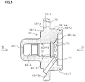
- FIG. 3 is a frontal view of a pilot (an arrow view seen from an arrow III of FIG. 5 );
- FIG. 4 is a back view of the pilot (an arrow view seen from an arrow IV of FIG. 5 );
- FIG. 5 is a vertical cross-sectional view of the pilot (an arrow cross-sectional view taken along a line V-V of FIG. 4 );
- FIG. 6 is another vertical cross-sectional view of the pilot (an arrow cross-sectional view taken along a line VI-VI of FIG. 4 ) ;
- FIG. 7 is a frontal view of a separator
- FIG. 8 is a vertical cross-sectional view of the separator (an arrow cross-sectional view taken along a line VIII-VIII of FIG. 7 );
- FIGS. 9 A, 9 B and 9 C are an explaining diagram of assembling processes (a), (b) and (c) of a lock-up clutch according to the first embodiment of the present invention, respectively;
- FIGS. 10 A and 10 B are an explaining diagram of the processes (d) and (e) which are subsequent to the processes shown in FIGS. 9 A to 9 C , respectively;
- FIGS. 11 A and 11 B are an explaining diagram of assembling processes (a) and (b) of a lock-up clutch according to another embodiment of the present invention, respectively;
- FIGS. 12 A and 12 B are an explaining diagram of the processes (c) and (d) which are subsequent to the processes shown in FIGS. 11 A and 11 B , respectively.
- FIGS. 1 and 2 show an upper cross-section and a lower cross-section of a torque converter along a center of an axis, respectively ( FIG. 1 shows an upper portion of the torque converter along the central line A-A and FIG. 2 shows a lower portion of the torque converter along the central line A-A).
- FIGS. 1 and 2 are called as a general view of the torque converter.
- An impeller shell 12 is fixed to a cover 10 by welding (the reference numeral 15 denotes a welded portion).
- a pump impeller 14 , a turbine shell 15 , a turbine blade 16 , a stator 18 , a one-way clutch 20 , which are well-known basic components of the torque converter, a torsional dumper 22 and a lock-up clutch 24 are installed in the closed chamber 13 that is formed by the cover 10 and the impeller shell 12 .
- Torque converter oil is circulated in the closed chamber and is also used as clutch oil for lubrication and cooling of a clutch pack described below of a lock-up clutch.
- the cover 10 includes an opening 10 - 1 with an axial center.
- a pilot 48 described below is welded (a welded portion 52 ) in an entire circumference at the opening 10 - 1 , resulting in maintaining oil-tightness of the closed chamber 13 .
- a hub damper 25 is disposed in a central portion of the closed chamber 13 and a turbine hub 26 is fitted into a boss 25 - 4 of the hub damper 25 .
- a spline hole 25 - 1 is formed on the hub damper 25 with the axial center and a spline 27 - 1 , which is disposed at one end of a transmission input axis 27 , is fitted into the spline hole 25 - 1 .
- a boss nut 28 is fixed to an outer surface of an engine side of the cover 10 by welding, a drive plate (not shown), which is coupled to a crank shaft of the engine (an engine motor of the present invention), is fixed to the boss nut 28 with a bolt (not shown), and the cover 10 integrally rotates with the crank shaft of the engine.
- the transmission input axis 27 is inserted into a stator shaft 29 , which is spline-fitted into a spline hole 20 - 1 a whose tip is an inner race 20 - 1 of the one-way clutch 20 .
- the reference numeral 29 - 1 denotes an outer circumferential spline of the stator shaft 29 which is fitted into the spline hole 20 - 1 a.
- the torsional damper 22 includes a drive plate 30 , a sub plate 31 , a hub plate 32 and coil springs 33 .
- the drive plate 30 is coupled to the sub plate 31 in an outer circumference by rivets 34 .
- the drive plate 30 and the sub plate 31 are coupled at the lock-up clutch 24 side.
- the drive plate 30 is opposite to the sub plate 31 in an axial direction.
- the drive plate 30 and the sub plate 31 have plural coil spring receiving portions 37 in a circumferential direction with an interval.
- the coil spring receiving portions 37 on the drive plate 30 have a molded portion 30 - 1 , those on the sub plate 31 have a molded portion 31 - 1 , and the molded portions 30 - 1 and 31 - 1 are oppositely protruded with one another.
- the coil springs 33 are received in a regular position of the respective coil spring receiving portions 37 with a setting load.
- the hub plate 32 of the present invention has a well-known structure, circumferential direction projections 32 - 1 which are disposed on an inner circumference of the hub plate 32 are engaged with circumferential direction grooves 25 - 2 which are disposed on an outer circumference of the hub damper 25 , and the hub plate 32 is rotatably coupled to the transmission input axis side.
- the hub plate 32 has driving portions 32 - 2 in which each of the driving portions 32 - 2 extends a portion between ends of the coil springs 33 , which are separately adjacent in a circumferential direction on an outer circumference, in a radial direction.
- the respective coil springs 33 are positioned at a rotational angle which is coincident with the corresponding coil spring receiving portion 37 , and the setting load is applied to the respective coil springs 33 .
- the torsional damper 22 performs an operation for absorbing the rotational fluctuation of the engine by elastic deformation of the coil springs 33 . That is, in the respective coil spring receiving portions 37 (the molded portions 30 - 1 and 31 - 1 ), the driving portions 32 - 2 of the hub plate 32 elastically deform the coil springs 33 between the ends of the opposite coil spring receiving portions in the rotational fluctuation direction by compression depending on the rotational fluctuation direction of the engine, which is deviated from the neutral state.
- the sub plate 31 is coupled to a turbine shell 15 and the hub damper 26 by the rivets 34 .
- the rivets 34 are made of a steel material, aluminum and a suitable metal material having ductility and the reference numeral 53 - 1 denotes an expanded head portion of the rivets 34 .
- the lock-up clutch 24 includes a clutch pack 36 , an outer clutch drum 38 (which is coupled to the drive plate 30 by rivets 39 ), an inner clutch drum 40 , an annular piston 42 , plural return springs 44 which are disposed in a circumferential direction with an interval, a separator 46 (a friction-engagement reaction force receiving member of the present invention) having an annular disk-shape, a pilot 48 (a piston guide member of the present invention), and a hydraulic pressure chamber 50 which is formed by the piston 42 , the separator 46 and the pilot 48 .
- the pilot 48 has a function in which the piston 42 is slidably guided in an axial direction on an inner circumference thereof.
- a front end 48 - 1 has a closed bottomed cylindrical-shape (see, FIGS. 5 and 6 ).
- the pilot 48 is welded to the opening 10 - 1 of the cover 10 with an axial center in an entire circumference for maintaining oil-tightness of the torque converter oil in the closed chamber 13 .
- the reference numeral 52 denotes the welded portion.
- a cylindrical portion 48 - 2 disposed at a rear end of the pilot 48 is inserted into an annular recess 25 - 3 of the hub damper 25 via the seal ring 54 (a groove 48 - 7 formed on the cylindrical portion 48 - 2 is to be an installing groove of the seal ring 54 as shown in FIGS. 5 and 6 ).
- a thrust bearing 56 is disposed between an opposite surface of the pilot 48 and that of the hub damper 25 in an axial direction.
- the cylindrical portion 48 - 2 of the pilot 48 has a flange portion 48 - 3 in an outer circumference, and the separator 46 is fixed to the flange portion 48 - 3 by crimping in which rivets 53 (fastening members of the present embodiment) are used.
- rivets 53 fastening members of the present embodiment
- the rivet holes 70 which are formed on the flange portion 48 - 3 of the pilot 48 , have a step-wise shape in which a front end of the rivet holes 70 (a side end of the cover 10 in the general view of the torque converter) has a larger diameter.
- the separator 46 includes the rivet holes 47 so that the respective rivet holes 47 are aligned with the corresponding rivet holes 70 which are formed on the flange portion 48 - 3 of the pilot 48 . As shown in FIG. 7 , eight rivet holes 47 are formed on the separator 46 in a circumferential direction with an equal interval.
- the rivets 53 are press-fitted from the cover 10 side into the rivet holes 70 of the flange portion 48 - 3 and the rivet holes 47 of the separator 46 . Since the head portion 53 - 1 of the rivets 53 hits a bottom surface of an expanded diameter portion 70 - 1 which is disposed at an inlet side of the rivet holes 70 (see, FIG. 5 ), further press-fitting of the rivets 53 is blocked.
- the head portion 53 - 1 of the rivets 53 is abutted to an opposite inner surface of the cover 10 , and the projection from the separator 46 is crimped (the reference numeral 53 - 3 denotes a crimped expanded diameter portion), resulting in realizing the strong fixing of the separator 46 to the pilot 48 .
- This fixing method by crimping is described below.
- the rivet holes 47 of the separator 46 include a recess 47 - 1 , which receives the crimped expanded diameter portion 53 - 3 of the rivets, at the rear surface side (see also, FIG. 8 ). As shown in FIGS.
- the pilot 48 has a cylindrical portion 48 - 4 , which serves as an inserting portion of a central opening 10 - 1 of the cover 10 , at the front surface side of the flange portion 48 - 3 , and the cylindrical portion 48 - 4 protrudes by a thickness of the cover 10 in front.
- the cover 10 is flush with the welded portion of the pilot 48 .
- the cylindrical portion 48 - 2 of the rear surface side of the flange portion 48 - 3 has slightly larger diameter at the vicinity of the flange portion 48 - 3 , and this expanded diameter portion 48 - 2 a serves as an inserting portion of the central hole 46 - 2 of the separator 46 in assembling the lock-up clutch.
- the clutch pack 36 includes plural annular disk-shape drive disks 58 , annular disk-shape driven disks 60 disposed between adjacent drive disks 58 , clutch facings 62 which are opposite to the drive disks 58 , are formed on both surfaces of the driven disks 60 and are made of a friction material (the first friction plate of the present invention includes the drive disk 58 and the clutch facing 62 , and the second friction plate of the present invention includes the driven disk 60 and the clutch facing 62 ).
- Projections 58 - 1 which are spaced with one another in a circumferential direction of the inner circumference of the drive disk 58 , are fitted into guide grooves 40 - 1 , which are extended to a longitudinal direction and are formed in a circumferential direction with an equal interval at the outer circumference of the inner clutch drum 40 .
- the drive disks 58 integrally rotate with the inner clutch drum 40 and the cover 10 and slidably move in a longitudinal direction.
- the front end of the inner clutch drum 40 which is an annular shape has a substantially L-shape cross-section 40 - 2 , and the substantially L-shape cross-section 40 - 2 is fixed to a cylindrical recess 10 - 2 opposite to the cover 10 by press-fitting and welding, and includes oil-holes 40 - 3 for the torque converter oil which serves as the clutch oil.
- the drive disk 58 which is the nearest to the cover 10 is opposite to the annular projections 10 - 3 formed on the cover 10 , and enables to receive the clutch engagement reaction force by cooperating with the separator 46 when the clutch is engaged.
- Projections 60 - 1 which are spaced with one another in a circumferential direction of the outer circumference of the driven disk 60 , are fitted into guide grooves 38 - 1 , which are extended to a longitudinal direction and are plurally formed in a circumferential direction with an interval at the inner circumference of the outer clutch drum 38 .
- the driven disks 60 integrally rotate with the outer clutch drum 38 and slidably move in a longitudinal direction.
- the outer clutch drum 38 is coupled to the sub plate 31 of a torsional damper 22 , which is one of the components of the transmission input axis 27 , by the rivets 39 .
- the return springs 44 make the piston 42 urge to a direction in which the piston 42 is separated to the cover 10 , the piston is abutted to the separator 46 at an abutment portion 42 - 3 , and the clutch pack 36 becomes a non-engagement state by oil film of the torque converter oil serving as the clutch oil, which exists between the drive disks 58 and the clutch facings 62 .
- the piston 42 moves toward the cover 10 against the return springs 44 (moves to leftward in the general view of the torque converter).
- the clutch pack 36 sandwiches between the cylindrical driving portion 42 - 1 of the piston 42 and the annular projections of the cover 10 , the drive disks 58 engage with the driven disks 60 via the clutch facings 62 , and then the lock-up clutch becomes the engagement state.
- the piston 42 moves toward the cover 10 . This movement is the same as that of Patent Document 3 and is different from those of Patent Documents 1 and 2 in which the clutch becomes the engagement state by making the piston move in the separation direction to the cover 10 .
- the inner circumference side of the piston 42 slidably fits the outer circumference of the flange portion 48 - 3 at an outer circumference of the pilot 48 in an axial direction via the seal ring 64 , and the outer circumference side of the piston 42 inserts into the axial direction cylindrical projection portion 46 - 1 of the outer circumference of the separator 46 (see, FIG. 8 ) via the seal ring 68 .
- the movement of the piston 42 toward the cover 10 which makes the lock-up clutch 24 become the engagement state, is performed by introducing the operation oil pressure to the hydraulic pressure chamber 50 which is constituted by the piston 42 , the separator 46 and the pilot 48 .
- the pilot 48 includes passage holes for introducing the operation oil to the hydraulic pressure chamber 50 , passage holes for circulating the torque converter oil and press-fitting holes of the rivets 53 for fixing the separator 46 to the cover. These hole structures of the pilot 48 will be described.
- the eight rivet holes 70 for press-fitting the rivets 53 into the flange portion 48 - 3 in an outer circumference of the pilot 48 are formed on the flange portion 48 - 3 in a circumferential direction with an equal interval, as shown in FIGS. 3 and 4 .
- the pilot 48 includes the central hole 48 - 6 whose front portion is closed.
- the inner circumferential surface 48 - 6 a of the open end surface side of the central hole 48 - 6 is a taper surface, and the torque converter oil holes 72 are opened to this taper surface 48 - 6 a .
- the eight torque converter oil holes 72 are formed on the flange portion 48 - 3 in a circumferential direction with an equal interval, as shown in FIG. 3 .
- the torque converter oil holes 72 are extended toward the front end portion 48 - 1 in inclination to an outer circumference side, and are opened to the corresponding rivet holes 70 in proximity to a circumferential direction at the recesses 48 - 3 a which are located on the front surface of the flange portion 48 - 3 (see, FIG. 3 ).
- these openings are denoted by “P”.
- the outer surface of an inner circumference of the piston 42 is opposite to the cover 10 at these openings “P”, and the torque converter oil communicates between the torque converter oil holes 72 of the pilot 48 and the closed chamber 13 .
- the number of the lock-up clutch operation oil holes 74 is also eight (see, FIG. 4 ), and as shown in FIG.
- the lock-up clutch operation oil holes 74 are extended from the inner circumferential holes of the pilot 48 toward the rear end surface side in inclination to an outer circumference side (the inclination from the inner side holes of the pilot 48 toward an outer circumference is the same as that of the oil holes 72 , but the inclination direction toward the rear end surface side in the holes 74 is opposite to the inclination direction toward the front end surface side in the holes 72 ).
- the lock-up clutch operation oil holes 74 are opened to the corresponding rivet holes 70 in proximity to a circumferential direction at the recesses 48 - 3 b which are located on the rear surface of the flange portion 48 - 3 .
- these openings are denoted by “Q” and are an inner circumferential portion of the hydraulic pressure chamber 50 .
- the lock-up clutch operation oil enables to communicate with (flow into) the hydraulic pressure chamber 50 .
- the openings of the lock-up clutch operation oil holes 74 are separated to the openings of the torque converter oil holes 72 on an inner circumferential surface of the central hole 48 - 6 of the pilot 48 in a direction of the closed front end side 48 - 1 of the pilot 48 , and a seal ring 76 is disposed between the openings of the lock-up clutch operation oil holes 74 and the openings of the torque converter oil holes 72 .
- the front surface portion 27 - 2 of the transmission input axis 27 is extended beyond the seal ring 76 .
- the operation oil pressure spaces 78 in front of the seal ring 76 and the torque converter oil spaces 80 in the rear of the seal ring 76 are separately formed.
- the central oil passage 82 of the transmission input axis 27 and the lock-up clutch operation oil hole 74 are opened.
- the torque converter oil hole 72 is opened.
- An installing groove of the seal ring 76 is denoted by the reference numeral 48 - 8 in FIGS. 5 and 6 .
- the torque converter oil is flown into the outer annular passage of the stator shaft 29 shown in an arrow f 1 , into the spline hole 25 - 1 of the hub damper 25 from stator shaft 29 shown in an arrow f 2 and into the torque converter oil space 80 .
- the torque converter oil is flown into the oil holes 72 from the torque converter oil space 80 (an arrow f 3 ) and into the clutch pack 36 from the oil holes 72 shown in an arrow f 4 .
- the closed chamber 13 is filled with the torque converter oil, resulting in supplying the torque converter oil into the torque converter.
- the torque converter oil from the torque converter is returned to the outer annular passage of the stator shaft 29 which is opposite to the flow-into side shown in an arrow f 5 and whose direction is reversed against the direction of the flow-into side (an arrow f 6 ).
- the flow-into outer annular passage (the arrow f 1 side) is separated to the flow-out outer annular passage by a not-shown means.
- the transmission input axis 27 has the operation oil holes 82 with an axial center, the respective operation oil holes 82 are opened to the corresponding operation oil pressure space 78 , and the operation oil pressure spaces 78 are opened to the hydraulic pressure chamber 50 , resulting in applying the operation oil pressure to the piston.
- the operation of the lock-up clutch 24 according to the present invention is the same as that of the normal lock-up clutch. Since the operation oil pressure of the hydraulic pressure chamber 50 is low in a non-lock-up state, the piston 42 is abutted to the separator 46 by the return springs 44 , the clutch pack 36 becomes a non-engagement state by the oil film between the drive disks 58 and the clutch facings 62 on the driven disks 60 , and the rotation of the crank shaft of the engine is transferred to the transmission input axis 27 by fluid power transmission by means of the torque converter.
- the flow of the operation oil which is transformed from the cover 10 to the impeller shell 12 and is generated by the rotation of the pump impeller 14 , is introduced to the turbine blade 16 via the stator 18 , resulting in circulating the operation oil to the pump impeller 14 .
- the rotation of the turbine blade 16 generated from the circulating flow of such an operation oil is transferred to the transmission input axis 27 via the turbine shell 15 , the sub plate 31 and the drive plate 30 of the torsional damper 22 , the coil springs 33 , the hub plate 32 and the hub damper 25 .
- the operation oil is introduced to the hydraulic pressure chamber 50 via the oil holes 82 of the transmission input axis 27 with an axial center and the oil holes 74 of the pilot 48 , the operation oil pressure of the hydraulic pressure chamber 50 is increased, the piston 42 is driven toward the cover 10 against the return springs 44 , and the drive disks 58 are engaged with the clutch facings 62 on the driven disks 60 in the clutch pack 36 , resulting in transiting the clutch pack 36 to an engagement state.
- the engagement of the clutch is directly performed by sandwiching and fixing between the piston 42 and the cover 10 in the clutch pack 36 by friction, and the engagement reaction force of the clutch is received by the cooperation with the projections 10 - 3 of the cover 10 and the separator 46 .
- the engagement reaction force of the clutch is received by the projections 10 - 3 of the cover 10 at one side of the clutch pack 36 and by the separator 46 at the other side (at the opposite side) of the clutch pack 36 via the piston 42 and the hydraulic pressure chamber 50 .
- the rotation of the crank shaft of the engine is transferred from the cover 10 to the inner side clutch drum 40 , the clutch pack 36 and the outer side clutch drum 38 in the lock-up clutch 24 , and is also transferred from the outer side clutch drum 38 to the hub damper 25 , that is, the transmission input axis 27 via the drive plate 30 , the coil springs 33 and the hub plate 26 in the torsional damper 22 .
- the impeller 14 , the turbine 16 and the stator 18 in the torque converter co-rotates the cover 10 with the same rotational velocity, the power transmission function by the torque converter is not generated, and the mechanical power transmission is only generated.
- FIG. 9 A shows a preparing state of the pilot 48 and the rivet 53 .
- the rivet 53 is press-fitted into the step-wise rivet hole 70 in the flange portion 48 - 3 of the pilot 48 , and the head portion 53 - 1 of the rivet 53 is flush with the flange portion 48 - 3 of the pilot 48 .
- the cover 10 which includes the welded boss nut 28 and is press-fitted and is fixed the inner side clutch drum 40 to the recess 10 - 2 by welding, is inserted into the cylindrical portion 48 - 4 of the front surface of the pilot 48 in the central hole 10 - 1 .
- the cover 10 is abutted to the head portion 53 - 1 of the rivet 53 which is press-fitted into the front surface of the flange portion 48 - 3 of the pilot 48 and the rivet hole 70 .
- a joint between the inner portion of the central hole 10 - 1 of the cover 10 and the cylindrical portion 48 - 4 of the front surface of the pilot 48 is welded in an entire circumference.
- the reference numeral 52 denotes the welded portion after welding.
- a die of a dedicated crimping apparatus (a crimper) is disposed at the cover 10 side via the head portions 53 - 1 of the rivets 53 , and the projection portions 53 - 2 from the rivet holes 70 of the separator 46 are crimped by punches of the crimper which is opposite to the die and whose number is the same as that of the rivets 53 .
- the above process is the crimping process, and the materials from the rivets 53 by crimping are flown toward the recess 47 - 1 of the separator 46 .
- the crimped portion (the expanded diameter portion) 53 - 3 generated by performing the crimping process of the rivets 53 is shown in FIG. 10 B in which a final process of (e) is illustrated.
- the outer clutch drum 38 of the clutch pack 36 is installed so that the guide grooves 38 - 1 of the outer clutch drum are engaged with the driven disks 60 .
- the outer clutch drum 38 is coupled to the drive plate 30 by the rivets 39 , and then the process is progressed to the assembling process in the next stage such as assembling the torque converter portion.
- the pilot 48 In the process prior to the process in which the pilot 48 is fixed to the separator 46 by crimping the rivets 39 , in a state that the respective head portions of the rivets 39 are press-fitted into the corresponding rivet holes 70 formed on the pilot 48 and are abutted to the cover, the pilot 48 is fixed to the cover 10 . Further, after the pilot 48 is fixed to the cover 10 , the seal ring 64 is in contact with the pilot 48 . After the seal ring 64 and 68 is in contact with the pilot 48 (the piston guide member), the pilot 48 (the piston guide member) is fixed to the separator 46 (the friction-engagement reaction force receiving portion) by crimping (by fixing with no heat). Thus, no heat is transferred to the seal ring 64 and 68 by the fixing operation, and the strong fixed state between the pilot 48 and the separator 46 is realized.
- the pilot 48 (the piston guide member) is fixed to the cover 10 in a state that the head portions 53 - 1 of the rivets (the fastening members) are abutted to the cover 10 after the respective head portions 53 - 1 of the rivets 53 (the fastening members) are press-fitted into the corresponding rivet holes 70 (the holes) formed on the pilot 48 (the piston guide member), the fastening of the rivets 53 (the fastening members) becomes strong. Thereby, when assembling other members such as the first and second friction plates 50 and 60 , the seal ring 64 and 68 and the piston 42 , to the lock-up clutch, it is not concerned that the rivets 53 (the fastening members) are dropped.
- the seal ring 64 and 68 is in contact with the pilot 48 (the piston guide member) after the pilot 48 (the piston guide member) is fixed to the cover 10 . That is, since the seal ring 64 and 68 is not in contact with the pilot 48 (the piston guide member) when the pilot 48 (the piston guide member) is fixed to the cover 10 , the fixing method in which the pilot 48 (the piston guide member) is fixed to the cover 10 can freely be selected. For example, the welding which is a strong fixing method as described in the present embodiment can be used in fixing the pilot 48 (the piston guide member) to the cover 10 .
- rivet-like projections for attaching the separator 46 to the pilot 48 can integrally be formed on the pilot 48 .
- the above configuration will be described as the second embodiment, and the assembling process will also be explained by using FIGS. 11 A to 12 B .
- the pilot 148 used in the second embodiment is shown in FIG. 11 A .
- the pilot 148 includes the rivet-like projections 153 (the fastening members in the second embodiment) which are integrated with the pilot 148 and are protruded to the pilot central hole opening end side (the separation side to the cover 10 in the general view of the torque converter) in the flange portion 148 - 3 .
- FIG. 11 B The state shown in FIG. 11 B is the same as the state shown in FIG. 9 C which is illustrating the assembling process of (c) in the first embodiment.
- the welded portion is shown by the reference numeral 52 .
- the inner side clutch drum 40 is press-fitted into and is welded to the recess 10 - 2 of the cover 10 .
- the next assembling process is shown in FIG. 12 A and is the same as the assembling process of (d) in the first embodiment ( FIG. 10 A ).
- the clutch pack 36 excluding the outer side clutch drum 38 , the piston 42 , the return springs 44 , the separator 46 , and the seal ring 64 and 68 are assembled to the pilot 148 .
- the end of the rivet-like projections 153 is protruded from the central hole 46 - 2 of the separator 46 .
- the assembling process (d) shown in FIG. 12 B is the same as the assembling process shown in FIG. 10 B of the first embodiment.
- the crimped portions 153 - 3 are formed by crimping the respective ends of the rivet-like projections 153 protruded from the separator 46 under adding the pressure, and the materials generated by crimping are received in the recess 47 - 1 of the separator 46 .
- the outer side clutch drum 38 of the clutch pack 36 is assembled to the pilot 148 , and then the assembling operation of the torque converter portion is performed.
- the rivet-like projections 153 are integrated with the pilot 148 , a decrease in the number of the components can be achieved, and the press-fitting process to the pilot 148 is not needed.
- the second embodiment of the present invention has the advantages in which the number of the components and the man-hour are reduced.
Abstract
Description
- Patent Document 1: WO 2009/049741 A1
- Patent Document 2: Japanese Unexamined Patent Publication No. 2008-538232 A
- Patent Document 3: Japanese Patent No. 5835391 B2
- 10 cover
- 10-1 central opening of cover
- 12 impeller shell
- 13 closed chamber
- 14 pump impeller
- 16 turbine blade
- 18 stator
- 20 one-way clutch
- 22 torsional damper
- 24 lock-up clutch
- 25 hub damper
- 27 transmission input axis
- 29 stator shaft
- 36 clutch pack
- 38 outer side clutch drum
- 40 inner side clutch drum
- 40-3 oil hole of inner side clutch drum
- 42 piston
- 44 return spring
- 46 separator (friction-engagement reaction force receiving member of the present invention)
- 47 rivet hole of separator
- 48, 148 pilot (piston guide member of the present invention)
- 50 hydraulic pressure chamber
- 52 welded portion between cover and pilot
- 53 rivet (fastening member of the present invention)
- 53-1 rivet head portion
- 53-3 crimped portion to rivet
- 58 drive disk
- 60 driven disk
- 62 clutch facing (the first friction plate constituted by a drive disk and a clutch facing; and the second friction plate constituted by a driven disk and a clutch facing)
- 70 rivet hole of pilot
- 72 torque converter oil hole of pilot
- 74 lock-up clutch operation oil hole of pilot
- 78 operation oil pressure space
- 80 torque converter oil space
- 82 clutch operation oil passage
- 153 rivet-like projection (fastening member of the present invention)
- 153-3 crimped portion of rivet-like projection integrated with pilot
Claims (12)
Applications Claiming Priority (4)
| Application Number | Priority Date | Filing Date | Title |
|---|---|---|---|
| JP2018164115 | 2018-09-03 | ||
| JP2018-164115 | 2018-09-03 | ||
| JPJP2018-164115 | 2018-09-03 | ||
| PCT/JP2019/032988 WO2020050056A1 (en) | 2018-09-03 | 2019-08-23 | Lock-up clutch for torque converter |
Publications (2)
| Publication Number | Publication Date |
|---|---|
| US20210215239A1 US20210215239A1 (en) | 2021-07-15 |
| US11519485B2 true US11519485B2 (en) | 2022-12-06 |
Family
ID=69722665
Family Applications (1)
| Application Number | Title | Priority Date | Filing Date |
|---|---|---|---|
| US17/270,545 Active US11519485B2 (en) | 2018-09-03 | 2019-08-23 | Lock-up clutch for torque converter |
Country Status (4)
| Country | Link |
|---|---|
| US (1) | US11519485B2 (en) |
| JP (1) | JP7184906B2 (en) |
| CN (1) | CN112437850B (en) |
| WO (1) | WO2020050056A1 (en) |
Families Citing this family (2)
| Publication number | Priority date | Publication date | Assignee | Title |
|---|---|---|---|---|
| WO2020096054A1 (en) * | 2018-11-08 | 2020-05-14 | ヴァレオカペックジャパン株式会社 | Lock-up apparatus for torque converter |
| US11635128B2 (en) * | 2021-03-18 | 2023-04-25 | Schaeffler Technologies AG & Co. KG | Torque converter with rivet connected stacked plates for a lock-up clutch |
Citations (9)
| Publication number | Priority date | Publication date | Assignee | Title |
|---|---|---|---|---|
| JP2002195378A (en) | 2000-12-26 | 2002-07-10 | Exedy Corp | Lockup device for fluid type torque transmission device |
| US6938744B2 (en) * | 2002-09-25 | 2005-09-06 | Exedy Corporation | Piston coupling mechanism, lockup device for a fluid-type torque transmission device, elastic coupling mechanism, and spring installation method for an elastic coupling mechanism |
| US6938743B2 (en) * | 2002-04-30 | 2005-09-06 | Valeo Embrayages | Hydrokinetic coupling apparatus, in particular for motor vehicles |
| US20080229570A1 (en) | 2005-02-11 | 2008-09-25 | Daimlerchrysler Ag | Method for Permanently Fixing at Least One Component to a Base Component Using a Plastically Deformed Bolt |
| WO2009049741A1 (en) | 2007-10-09 | 2009-04-23 | Daimler Ag | Torque converter |
| DE102012221411A1 (en) * | 2011-12-14 | 2013-06-20 | Schaeffler Technologies AG & Co. KG | Power transmission device for use in powertrain of motor car, has mold element riveted or welded with housing by bolt or weld seam, where chamber and friction elements are arranged between housing and mold element to press elements together |
| US8727087B2 (en) * | 2011-02-09 | 2014-05-20 | Zf Friedrichshafen Ag | Torque transmission arrangement, particularly hydrodynamic torque converter |
| JP5835391B2 (en) | 2011-03-31 | 2015-12-24 | アイシン・エィ・ダブリュ株式会社 | Starting device |
| US10527145B2 (en) * | 2017-01-12 | 2020-01-07 | GM Global Technology Operations LLC | Torque converter assembly and a vehicle including the torque converter assembly |
Family Cites Families (2)
| Publication number | Priority date | Publication date | Assignee | Title |
|---|---|---|---|---|
| DE10350935B4 (en) * | 2002-11-16 | 2019-02-21 | Schaeffler Technologies AG & Co. KG | torque converter |
| JP6654072B2 (en) * | 2016-03-18 | 2020-02-26 | 株式会社エクセディ | Lockup device for torque converter |
-
2019
- 2019-08-23 WO PCT/JP2019/032988 patent/WO2020050056A1/en active Application Filing
- 2019-08-23 JP JP2020541130A patent/JP7184906B2/en active Active
- 2019-08-23 US US17/270,545 patent/US11519485B2/en active Active
- 2019-08-23 CN CN201980047987.3A patent/CN112437850B/en active Active
Patent Citations (10)
| Publication number | Priority date | Publication date | Assignee | Title |
|---|---|---|---|---|
| JP2002195378A (en) | 2000-12-26 | 2002-07-10 | Exedy Corp | Lockup device for fluid type torque transmission device |
| US6938743B2 (en) * | 2002-04-30 | 2005-09-06 | Valeo Embrayages | Hydrokinetic coupling apparatus, in particular for motor vehicles |
| US6938744B2 (en) * | 2002-09-25 | 2005-09-06 | Exedy Corporation | Piston coupling mechanism, lockup device for a fluid-type torque transmission device, elastic coupling mechanism, and spring installation method for an elastic coupling mechanism |
| US20080229570A1 (en) | 2005-02-11 | 2008-09-25 | Daimlerchrysler Ag | Method for Permanently Fixing at Least One Component to a Base Component Using a Plastically Deformed Bolt |
| JP2008538232A (en) | 2005-02-11 | 2008-10-16 | ダイムラー・アクチェンゲゼルシャフト | Method for releasably securing at least one part to a base part using plastic deformation bolts |
| WO2009049741A1 (en) | 2007-10-09 | 2009-04-23 | Daimler Ag | Torque converter |
| US8727087B2 (en) * | 2011-02-09 | 2014-05-20 | Zf Friedrichshafen Ag | Torque transmission arrangement, particularly hydrodynamic torque converter |
| JP5835391B2 (en) | 2011-03-31 | 2015-12-24 | アイシン・エィ・ダブリュ株式会社 | Starting device |
| DE102012221411A1 (en) * | 2011-12-14 | 2013-06-20 | Schaeffler Technologies AG & Co. KG | Power transmission device for use in powertrain of motor car, has mold element riveted or welded with housing by bolt or weld seam, where chamber and friction elements are arranged between housing and mold element to press elements together |
| US10527145B2 (en) * | 2017-01-12 | 2020-01-07 | GM Global Technology Operations LLC | Torque converter assembly and a vehicle including the torque converter assembly |
Non-Patent Citations (1)
| Title |
|---|
| International Search Report with English translation and Written Opinion issued in corresponding application No. PCT/JP2019/032988 dated Oct. 8, 2019. |
Also Published As
| Publication number | Publication date |
|---|---|
| JPWO2020050056A1 (en) | 2021-08-26 |
| WO2020050056A1 (en) | 2020-03-12 |
| CN112437850B (en) | 2024-03-29 |
| US20210215239A1 (en) | 2021-07-15 |
| CN112437850A (en) | 2021-03-02 |
| JP7184906B2 (en) | 2022-12-06 |
Similar Documents
| Publication | Publication Date | Title |
|---|---|---|
| US9494221B2 (en) | Torque converter clutch with low back pressure | |
| JP4935006B2 (en) | Fluid transmission device | |
| US7287630B2 (en) | Torque converter with lockup clutch | |
| US9140307B2 (en) | Clutch arrangement and sealing element | |
| US20070221468A1 (en) | Hydraulically actuated double clutch | |
| CN110248836B (en) | Motor vehicle clutch assembly including a stop for limiting the removal of the clutch plate assembly | |
| US8376105B2 (en) | Lock-up clutch mechanism | |
| US6938744B2 (en) | Piston coupling mechanism, lockup device for a fluid-type torque transmission device, elastic coupling mechanism, and spring installation method for an elastic coupling mechanism | |
| US11519485B2 (en) | Lock-up clutch for torque converter | |
| US6193036B1 (en) | Hydrokinetic coupling apparatus with lock-up clutch for motor vehicle | |
| US7201261B2 (en) | Bridging clutch for a hydrodynamic clutch device enclosed by a housing | |
| US9140308B2 (en) | Clutch arrangement | |
| JP2008038951A (en) | Fluid type torque transmitting apparatus | |
| US10072624B2 (en) | Starting element | |
| JP2004502103A (en) | Fluid coupling devices for automobiles, etc. | |
| US6280333B1 (en) | Hydrokinetic coupling apparatus with locking clutch for motor vehicle | |
| US20100059324A1 (en) | Coupling Arrangement, Particularly for a Hydrodynamic Coupling Device | |
| US10260611B2 (en) | Hydrokinetic torque coupling device having turbine-piston lockup clutch, and related methods | |
| CN115038888A (en) | Hybrid power drive module | |
| US20150008089A1 (en) | Clutch Arrangement | |
| US8042666B2 (en) | Hydrodynamic clutch device | |
| US20080277225A1 (en) | Three-pass torque converter with sealed piston and forced cooling flow | |
| US20070284206A1 (en) | Pilot plate torque transmitting assembly for a torque converter | |
| US20170167586A1 (en) | Torque converter lockup clutch including piston shim | |
| JP3601522B2 (en) | Damper device |
Legal Events
| Date | Code | Title | Description |
|---|---|---|---|
| AS | Assignment |
Owner name: UNIPRES CORPORATION, JAPAN Free format text: ASSIGNMENT OF ASSIGNORS INTEREST;ASSIGNORS:FURUYA, NOBUHIKO;MORI, RYUTA;TAKO, MITSUYOSHI;AND OTHERS;SIGNING DATES FROM 20210127 TO 20210209;REEL/FRAME:055365/0416 Owner name: JATCO LTD, JAPAN Free format text: ASSIGNMENT OF ASSIGNORS INTEREST;ASSIGNORS:FURUYA, NOBUHIKO;MORI, RYUTA;TAKO, MITSUYOSHI;AND OTHERS;SIGNING DATES FROM 20210127 TO 20210209;REEL/FRAME:055365/0416 Owner name: NISSAN MOTOR CO., LTD., JAPAN Free format text: ASSIGNMENT OF ASSIGNORS INTEREST;ASSIGNORS:FURUYA, NOBUHIKO;MORI, RYUTA;TAKO, MITSUYOSHI;AND OTHERS;SIGNING DATES FROM 20210127 TO 20210209;REEL/FRAME:055365/0416 |
|
| FEPP | Fee payment procedure |
Free format text: ENTITY STATUS SET TO UNDISCOUNTED (ORIGINAL EVENT CODE: BIG.); ENTITY STATUS OF PATENT OWNER: LARGE ENTITY |
|
| STPP | Information on status: patent application and granting procedure in general |
Free format text: DOCKETED NEW CASE - READY FOR EXAMINATION |
|
| STPP | Information on status: patent application and granting procedure in general |
Free format text: NON FINAL ACTION MAILED |
|
| STPP | Information on status: patent application and granting procedure in general |
Free format text: RESPONSE TO NON-FINAL OFFICE ACTION ENTERED AND FORWARDED TO EXAMINER |
|
| STPP | Information on status: patent application and granting procedure in general |
Free format text: NOTICE OF ALLOWANCE MAILED -- APPLICATION RECEIVED IN OFFICE OF PUBLICATIONS |
|
| STPP | Information on status: patent application and granting procedure in general |
Free format text: PUBLICATIONS -- ISSUE FEE PAYMENT VERIFIED |
|
| STCF | Information on status: patent grant |
Free format text: PATENTED CASE |