US11493441B2 - Flow cell, read head, and skid attachment - Google Patents
Flow cell, read head, and skid attachment Download PDFInfo
- Publication number
- US11493441B2 US11493441B2 US16/744,172 US202016744172A US11493441B2 US 11493441 B2 US11493441 B2 US 11493441B2 US 202016744172 A US202016744172 A US 202016744172A US 11493441 B2 US11493441 B2 US 11493441B2
- Authority
- US
- United States
- Prior art keywords
- flow cell
- read head
- tube
- push rod
- flange
- Prior art date
- Legal status (The legal status is an assumption and is not a legal conclusion. Google has not performed a legal analysis and makes no representation as to the accuracy of the status listed.)
- Active, expires
Links
- VYPSYNLAJGMNEJ-UHFFFAOYSA-N Silicium dioxide Chemical compound O=[Si]=O VYPSYNLAJGMNEJ-UHFFFAOYSA-N 0.000 claims description 17
- 239000005350 fused silica glass Substances 0.000 claims description 17
- 239000000463 material Substances 0.000 claims description 10
- 230000003287 optical effect Effects 0.000 claims description 3
- 239000000126 substance Substances 0.000 claims description 3
- 239000011521 glass Substances 0.000 claims description 2
- 229910052594 sapphire Inorganic materials 0.000 claims description 2
- 239000010980 sapphire Substances 0.000 claims description 2
- 238000000569 multi-angle light scattering Methods 0.000 abstract description 5
- 238000011143 downstream manufacturing Methods 0.000 abstract description 4
- 238000012993 chemical processing Methods 0.000 description 4
- 238000010586 diagram Methods 0.000 description 1
- 238000005516 engineering process Methods 0.000 description 1
- 238000005259 measurement Methods 0.000 description 1
- 238000012986 modification Methods 0.000 description 1
- 230000004048 modification Effects 0.000 description 1
Images


Classifications
-
- G—PHYSICS
- G01—MEASURING; TESTING
- G01N—INVESTIGATING OR ANALYSING MATERIALS BY DETERMINING THEIR CHEMICAL OR PHYSICAL PROPERTIES
- G01N21/00—Investigating or analysing materials by the use of optical means, i.e. using sub-millimetre waves, infrared, visible or ultraviolet light
- G01N21/17—Systems in which incident light is modified in accordance with the properties of the material investigated
- G01N21/47—Scattering, i.e. diffuse reflection
- G01N21/49—Scattering, i.e. diffuse reflection within a body or fluid
- G01N21/51—Scattering, i.e. diffuse reflection within a body or fluid inside a container, e.g. in an ampoule
-
- G—PHYSICS
- G01—MEASURING; TESTING
- G01N—INVESTIGATING OR ANALYSING MATERIALS BY DETERMINING THEIR CHEMICAL OR PHYSICAL PROPERTIES
- G01N21/00—Investigating or analysing materials by the use of optical means, i.e. using sub-millimetre waves, infrared, visible or ultraviolet light
- G01N21/01—Arrangements or apparatus for facilitating the optical investigation
- G01N21/03—Cuvette constructions
- G01N21/05—Flow-through cuvettes
-
- G—PHYSICS
- G01—MEASURING; TESTING
- G01N—INVESTIGATING OR ANALYSING MATERIALS BY DETERMINING THEIR CHEMICAL OR PHYSICAL PROPERTIES
- G01N21/00—Investigating or analysing materials by the use of optical means, i.e. using sub-millimetre waves, infrared, visible or ultraviolet light
- G01N21/17—Systems in which incident light is modified in accordance with the properties of the material investigated
- G01N21/47—Scattering, i.e. diffuse reflection
- G01N21/49—Scattering, i.e. diffuse reflection within a body or fluid
- G01N21/53—Scattering, i.e. diffuse reflection within a body or fluid within a flowing fluid, e.g. smoke
-
- G—PHYSICS
- G01—MEASURING; TESTING
- G01N—INVESTIGATING OR ANALYSING MATERIALS BY DETERMINING THEIR CHEMICAL OR PHYSICAL PROPERTIES
- G01N21/00—Investigating or analysing materials by the use of optical means, i.e. using sub-millimetre waves, infrared, visible or ultraviolet light
- G01N21/84—Systems specially adapted for particular applications
- G01N21/85—Investigating moving fluids or granular solids
-
- G—PHYSICS
- G01—MEASURING; TESTING
- G01N—INVESTIGATING OR ANALYSING MATERIALS BY DETERMINING THEIR CHEMICAL OR PHYSICAL PROPERTIES
- G01N21/00—Investigating or analysing materials by the use of optical means, i.e. using sub-millimetre waves, infrared, visible or ultraviolet light
- G01N21/17—Systems in which incident light is modified in accordance with the properties of the material investigated
- G01N21/47—Scattering, i.e. diffuse reflection
- G01N2021/4704—Angular selective
- G01N2021/4711—Multiangle measurement
-
- G—PHYSICS
- G01—MEASURING; TESTING
- G01N—INVESTIGATING OR ANALYSING MATERIALS BY DETERMINING THEIR CHEMICAL OR PHYSICAL PROPERTIES
- G01N21/00—Investigating or analysing materials by the use of optical means, i.e. using sub-millimetre waves, infrared, visible or ultraviolet light
- G01N21/17—Systems in which incident light is modified in accordance with the properties of the material investigated
- G01N21/47—Scattering, i.e. diffuse reflection
- G01N21/49—Scattering, i.e. diffuse reflection within a body or fluid
- G01N21/51—Scattering, i.e. diffuse reflection within a body or fluid inside a container, e.g. in an ampoule
- G01N2021/513—Cuvettes for scattering measurements
Definitions
- the present disclosure relates to multi-angle light scattering, and more specifically, to a flow cell, a read head, and a skid attachment for measuring real-time molecular weight for downstream process control.
- the present disclosure describes a flow cell, a read head, and a skid attachment for measuring real-time molecular weight for downstream process control.
- the flow cell comprises (1) a hollow cylindrical tube, (2) an inlet flange connected to an inlet of the tube, and (3) an outlet flange connected to an outlet of the tube.
- the read head comprises (1) at least one push rod, (2) at least two line contacts, where the at least one push rod is configured to push an outer side wall of a flow cell against the at least two line contacts, thereby registering the flow cell within the read head.
- the skid attachment comprises a plurality of arms connected to an enclosure configured to house at least a multi-angle light scattering instrument comprising a read head, where the enclosure is configured to be connected to a skid via the plurality of arms, where the skid is configured to house chemical processing equipment.
- FIG. 1 depicts a block diagram in accordance with an exemplary embodiment.
- FIG. 2A depicts a flow cell in accordance with an exemplary embodiment.
- FIG. 2B depicts a flow cell in accordance with an exemplary embodiment.
- FIG. 2C depicts a flow cell in accordance with an exemplary embodiment.
- FIG. 2D depicts a flow cell in accordance with an exemplary embodiment.
- FIG. 2E depicts a flow cell in accordance with an exemplary embodiment.
- FIG. 2F depicts a flow cell in accordance with an exemplary embodiment.
- FIG. 2G depicts a flow cell in accordance with an exemplary embodiment.
- FIG. 3 depicts a flow cell in accordance with an exemplary embodiment.
- FIG. 4A depicts a read head in accordance with an exemplary embodiment.
- FIG. 4B depicts a read head in accordance with an exemplary embodiment.
- FIG. 4C depicts a read head in accordance with an exemplary embodiment.
- FIG. 4D depicts a read head in accordance with an exemplary embodiment.
- FIG. 4E depicts a read head in accordance with an exemplary embodiment.
- FIG. 4F depicts a read head in accordance with an exemplary embodiment.
- FIG. 4G depicts a read head in accordance with an exemplary embodiment.
- FIG. 4H depicts a read head in accordance with an exemplary embodiment.
- FIG. 4I depicts a read head in accordance with an exemplary embodiment.
- FIG. 4J depicts a read head in accordance with an exemplary embodiment
- FIG. 5A depicts a skid attachment in accordance with an exemplary embodiment.
- FIG. 5B depicts a skid attachment in accordance with an exemplary embodiment.
- FIG. 5C depicts a skid attachment in accordance with an exemplary embodiment.
- FIG. 6A depicts a skid attachment in accordance with an exemplary embodiment.
- FIG. 6B depicts a skid attachment in accordance with an exemplary embodiment.
- FIG. 6C depicts a skid attachment in accordance with an exemplary embodiment.
- FIG. 7A depicts a skid attachment in accordance with an exemplary embodiment.
- FIG. 7B depicts a skid attachment in accordance with an exemplary embodiment.
- FIG. 7C depicts a skid attachment in accordance with an exemplary embodiment.
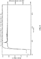
- FIG. 8 depicts a graph in accordance with an embodiment
- the present disclosure describes a flow cell, a read head, and a skid attachment for measuring real-time molecular weight for downstream process control.
- the flow cell comprises (1) a hollow cylindrical tube, (2) an inlet flange connected to an inlet of the tube, and (3) an outlet flange connected to an outlet of the tube.
- the read head comprises (1) at least one push rod, (2) at least two line contacts, where the at least one push rod is configured to push an outer side wall of a flow cell against the at least two line contacts, thereby registering the flow cell within the read head.
- the skid attachment comprises a plurality of arms connected to an enclosure configured to house at least a multi-angle light scattering instrument comprising a read head, where the enclosure is configured to be connected to a skid via the plurality of arms, where the skid is configured to house chemical processing equipment.
- the flow cell is depicted in FIG. 2A , FIG. 2B , FIG. 2C , FIG. 2D , FIG. 2E , FIG. 2F , FIG. 2G , and FIG. 3 .
- the flow cell includes a hollow cylindrical tube 210 , an inlet flange 220 connected to an inlet 212 of tube 210 , and an outlet flange 230 connected to an outlet 214 of tube 210 .
- tube 210 includes an orientation indicator 240 configured to allow the flow cell to be positioned within a read head.
- tube 210 , inlet flange 220 , and outlet flange 230 include an optically clear material.
- tube 210 , inlet flange 220 , and outlet flange 230 are an optically clear material.
- tube 210 , inlet flange 220 , and outlet flange 230 include a material with the optical qualities, the chemical resistivity, and the strength of fused quartz.
- tube 210 , inlet flange 220 , and outlet flange 230 are a material with the optical qualities, the chemical resistivity, and the strength of fused quartz.
- the material is one of fused silica, sapphire, borosilicate, Schott N-K5 glass, and fused quartz.
- tube 210 , inlet flange 220 , and outlet flange 230 include fused quartz.
- tube 210 , inlet flange 220 , and outlet flange 230 are fused quartz.
- tube 210 , inlet flange 220 , and outlet flange 230 include a material with at least the Young's modulus of fused silica, at least the tensile strength of fused silica, at least the sheer strength of fused silica, and at least the yield strength of fused silica.
- tube 210 , inlet flange 220 , and outlet flange 230 are a material with at least the Young's modulus of fused silica, at least the tensile strength of fused silica, at least the sheer strength of fused silica, and at least the yield strength of fused silica.
- tube 210 has a concentricity of less than 0.13. In a particular embodiment, tube 210 has a concentricity greater than or equal to 0.05 and less than or equal to 0.07. In an embodiment, tube 210 , inlet flange 220 , and outlet flange 230 have a scratch dig between 10-5 and 20-10.
- tube 210 , inlet flange 220 , and outlet flange 230 are compatible with industry standard sanitary tri-clamp fittings. In an embodiment, tube 210 , inlet flange 220 , and outlet flange 230 are gamma-sterilizable. In an embodiment, tube 210 , inlet flange 220 , and outlet flange 230 are disposable. In an embodiment, tube 210 , inlet flange 220 , and outlet flange 230 are compatible with a volume flow rate of greater than or equal to 20 L/minute.
- the read head is depicted in FIG. 4A , FIG. 4B , FIG. 4C , FIG. 4D , FIG. 4E , FIG. 4F , FIG. 4G , FIG. 4H , FIG. 4I , and FIG. 4J .
- the read head includes at least one push rod 410 , at least two line contacts 420 , 430 , and where at least one push rod 410 is configured to push an outer side wall of a flow cell against at least two line contacts 420 , 430 , thereby registering the flow cell within the read head.
- the read head is configured to hold the flow cell in a flow cell holder, where the flow cell and the flow cell holder are concentric.
- the read head further includes a lever 440 connected to push rod 410 , where lever 440 is configured to be moved in a first direction to move push rod 410 to push the outer side wall of the flow cell against at least two line contacts 420 , 430 , thereby registering the flow cell within the read head, and where lever 440 is configured to be moved in a second direction to move push rod 410 away from the outer side wall of the flow cell, thereby releasing the flow cell from at least two line contacts 420 , 430 , thereby releasing the flow cell from the read head.
- each of at least two line contacts 420 , 430 include a first line contact piece; and a second line contact piece in line with the first line contact piece and separated from the first line contact piece by a distance.
- the distance is at least 0.5 in.
- a spring, a cam, a hydraulic press, an electric servo motor, a pneumatic press, or a screw is connected to push rod 410 , where the spring, the cam, the hydraulic press, the electric servo motor, the pneumatic press, or the screw is configured to be moved in a first direction to move push rod 410 to push the outer side wall of the flow cell against at least two line contacts 420 , 430 , thereby registering the flow cell within the read head, and where the spring, the cam, the hydraulic press, the electric servo motor, the pneumatic press, or the screw is configured to be moved in a second direction to move push rod 410 away from the outer side wall of the flow cell, thereby releasing the flow cell from at least two line contacts 420 , 430 , thereby releasing the flow cell from the read head. Registering the flow cell within the read head could allow for more accurate measurements from the flow cell.
- the read head includes at least one push rod, at least three point contacts, and where the at least one push rod is configured to push an outer side wall of a flow cell against the at least three point contacts, thereby registering the flow cell within the read head.
- a read head further includes a lever connected to the push rod, where the lever is configured to be moved in a first direction to move the push rod to push the outer side wall of the flow cell against the at least three point contacts, thereby registering the flow cell within the read head, and where the lever is configured to be moved in a second direction to move the push rod away from the outer side wall of the flow cell, thereby releasing the flow cell from the at least three point contacts, thereby releasing the flow cell from the read head.
- the skid attachment is depicted in FIG. 5A , FIG. 5B , FIG. 5C , FIG. 6A , FIG. 6B , FIG. 6C , FIG. 7A , FIG. 7B , and FIG. 7C .
- the skid attachment includes a plurality of arms connected to an enclosure 540 configured to house at least a multi-angle light scattering instrument comprising a read head.
- the plurality of arms include at least four arms.
- the plurality of arms include at least two sets of arms 512 , 516 wherein each of at least two sets of arms 512 , 516 includes two arms 520 , 522 , 526 , 528 connected to an enclosure holder 530 , 532 configured to be connected to enclosure 540 .
- enclosure 540 is configured to be connected to a skid via the plurality of arms.
- the skid is configured to house chemical processing equipment.
- the plurality of arms further include at least two pins 550 , 552 , where at least two pins 550 , 552 are configured to couple together at least two sets of arms thereby connecting the plurality of arms and enclosure 540 to the skid.
- FIG. 8 depicts the performance of the flow cell when connected to chemical processing equipment.
Abstract
Description
Claims (10)
Priority Applications (4)
| Application Number | Priority Date | Filing Date | Title |
|---|---|---|---|
| US16/744,172 US11493441B2 (en) | 2019-01-15 | 2020-01-15 | Flow cell, read head, and skid attachment |
| PCT/US2021/013758 WO2021146645A2 (en) | 2019-01-15 | 2021-01-15 | Flow cell, read head, and skid attachment |
| EP21741565.2A EP4090943A2 (en) | 2019-01-15 | 2021-01-15 | Flow cell, read head, and skid attachment |
| US17/983,383 US20230068952A1 (en) | 2019-01-15 | 2022-11-08 | Read head |
Applications Claiming Priority (2)
| Application Number | Priority Date | Filing Date | Title |
|---|---|---|---|
| US201962792403P | 2019-01-15 | 2019-01-15 | |
| US16/744,172 US11493441B2 (en) | 2019-01-15 | 2020-01-15 | Flow cell, read head, and skid attachment |
Related Child Applications (1)
| Application Number | Title | Priority Date | Filing Date |
|---|---|---|---|
| US17/983,383 Continuation US20230068952A1 (en) | 2019-01-15 | 2022-11-08 | Read head |
Publications (2)
| Publication Number | Publication Date |
|---|---|
| US20200225155A1 US20200225155A1 (en) | 2020-07-16 |
| US11493441B2 true US11493441B2 (en) | 2022-11-08 |
Family
ID=71516438
Family Applications (2)
| Application Number | Title | Priority Date | Filing Date |
|---|---|---|---|
| US16/744,172 Active 2040-07-06 US11493441B2 (en) | 2019-01-15 | 2020-01-15 | Flow cell, read head, and skid attachment |
| US17/983,383 Pending US20230068952A1 (en) | 2019-01-15 | 2022-11-08 | Read head |
Family Applications After (1)
| Application Number | Title | Priority Date | Filing Date |
|---|---|---|---|
| US17/983,383 Pending US20230068952A1 (en) | 2019-01-15 | 2022-11-08 | Read head |
Country Status (3)
| Country | Link |
|---|---|
| US (2) | US11493441B2 (en) |
| EP (1) | EP4090943A2 (en) |
| WO (1) | WO2021146645A2 (en) |
Families Citing this family (1)
| Publication number | Priority date | Publication date | Assignee | Title |
|---|---|---|---|---|
| US10466173B2 (en) * | 2017-10-06 | 2019-11-05 | Wyatt Technology Corporation | Optical flow cell assembly incorporating a replaceable transparent flow cell |
Citations (7)
| Publication number | Priority date | Publication date | Assignee | Title |
|---|---|---|---|---|
| US5938982A (en) * | 1996-09-20 | 1999-08-17 | Sugiura; Eiichi | Device for fining bubbles of gas contained in liquid |
| US20020171836A1 (en) * | 2001-01-18 | 2002-11-21 | Yuri Gerner | Flow cells utilizing photometric techniques |
| US20080289427A1 (en) * | 2005-05-04 | 2008-11-27 | Robert Kurt Brandt | Method and Apparatus of Detecting an Object |
| GB2462606A (en) * | 2008-08-11 | 2010-02-17 | Toshiba Res Europ Ltd | A reading system and method for reading encoded carriers |
| US20140266266A1 (en) * | 2013-03-12 | 2014-09-18 | Dionex Softron Gmbh | Flow cell |
| US20160091365A1 (en) * | 2014-09-30 | 2016-03-31 | Perkinelmer Health Sciences, Inc. | Flow cell modules and liquid sample analyzers and methods including same |
| DE102016125043A1 (en) * | 2016-12-20 | 2017-04-13 | Agilent Technologies, Inc. - A Delaware Corporation - | Pressure stable flow cell |
Family Cites Families (6)
| Publication number | Priority date | Publication date | Assignee | Title |
|---|---|---|---|---|
| US2599577A (en) * | 1947-10-08 | 1952-06-10 | Norgren Co C A | Balanced fluid pressure regulating valve |
| US3928140A (en) * | 1974-05-10 | 1975-12-23 | Philip J Wyatt | Apparatus and process for testing microparticle response to its environment |
| US6476908B1 (en) * | 2000-04-10 | 2002-11-05 | Eclipse Optics, Inc. | Optical probe |
| US8951781B2 (en) * | 2011-01-10 | 2015-02-10 | Illumina, Inc. | Systems, methods, and apparatuses to image a sample for biological or chemical analysis |
| EP4219012A1 (en) * | 2012-04-03 | 2023-08-02 | Illumina, Inc. | Method of imaging a substrate comprising fluorescent features and use of the method in nucleic acid sequencing |
| US10466173B2 (en) * | 2017-10-06 | 2019-11-05 | Wyatt Technology Corporation | Optical flow cell assembly incorporating a replaceable transparent flow cell |
-
2020
- 2020-01-15 US US16/744,172 patent/US11493441B2/en active Active
-
2021
- 2021-01-15 EP EP21741565.2A patent/EP4090943A2/en active Pending
- 2021-01-15 WO PCT/US2021/013758 patent/WO2021146645A2/en unknown
-
2022
- 2022-11-08 US US17/983,383 patent/US20230068952A1/en active Pending
Patent Citations (7)
| Publication number | Priority date | Publication date | Assignee | Title |
|---|---|---|---|---|
| US5938982A (en) * | 1996-09-20 | 1999-08-17 | Sugiura; Eiichi | Device for fining bubbles of gas contained in liquid |
| US20020171836A1 (en) * | 2001-01-18 | 2002-11-21 | Yuri Gerner | Flow cells utilizing photometric techniques |
| US20080289427A1 (en) * | 2005-05-04 | 2008-11-27 | Robert Kurt Brandt | Method and Apparatus of Detecting an Object |
| GB2462606A (en) * | 2008-08-11 | 2010-02-17 | Toshiba Res Europ Ltd | A reading system and method for reading encoded carriers |
| US20140266266A1 (en) * | 2013-03-12 | 2014-09-18 | Dionex Softron Gmbh | Flow cell |
| US20160091365A1 (en) * | 2014-09-30 | 2016-03-31 | Perkinelmer Health Sciences, Inc. | Flow cell modules and liquid sample analyzers and methods including same |
| DE102016125043A1 (en) * | 2016-12-20 | 2017-04-13 | Agilent Technologies, Inc. - A Delaware Corporation - | Pressure stable flow cell |
Non-Patent Citations (1)
| Title |
|---|
| Technical product catalog 2016 by EVAC AG (Year: 2016). * |
Also Published As
| Publication number | Publication date |
|---|---|
| WO2021146645A2 (en) | 2021-07-22 |
| US20230068952A1 (en) | 2023-03-02 |
| EP4090943A2 (en) | 2022-11-23 |
| WO2021146645A3 (en) | 2021-09-16 |
| US20200225155A1 (en) | 2020-07-16 |
Similar Documents
| Publication | Publication Date | Title |
|---|---|---|
| US20230068952A1 (en) | Read head | |
| AU597168B2 (en) | Sensor and method for detecting the presence of air bubbles in liquid | |
| JP2005529327A5 (en) | ||
| JPH04265844A (en) | Optical probe | |
| US4469398A (en) | Optical connector for use during photometric analysis | |
| US9958321B2 (en) | Transverse optical transmission probe | |
| CN103698304A (en) | Shear type liquid core coupled surface plasma resonance imaging analyzer | |
| CN210165914U (en) | Porous pneumatic measuring instrument inner diameter measuring head and pneumatic measuring instrument | |
| US2182280A (en) | Static pressure measuring device | |
| CN204374074U (en) | Liquid absorbance proving installation | |
| CN202013454U (en) | Integral fiber laser collimator and manufacturing device thereof | |
| CN206563544U (en) | Portable herbage area measuring device | |
| CN113721323A (en) | Novel multi-core optical fiber coupling device and preparation method | |
| CN209044114U (en) | A kind of Novel portable optical splitter | |
| CN202939126U (en) | Device for measuring liquid refracting index on basis of two-slit interference principle | |
| CN105891971A (en) | Simple-structure type fiber connector | |
| CN109985679A (en) | A kind of SPR detector multichannel micro-fluidic chip grasping system | |
| CN111413283B (en) | Optical fiber gas sensor based on butterfly wing scales | |
| CN212585791U (en) | High-precision detection sensor | |
| CN214149076U (en) | Taper diameter measuring equipment | |
| CN109099996A (en) | A kind of minute gas flowmeter calibrating installation | |
| CN102129129A (en) | Integrated optical fiber laser collimator and manufacturing device thereof | |
| CN114226182B (en) | Optical fiber strain sensor laying and positioning device for circular section tubular beams | |
| CN215469429U (en) | FDS equipment centering mechanism | |
| CN210182684U (en) | Cable locking device for measuring instrument |
Legal Events
| Date | Code | Title | Description |
|---|---|---|---|
| FEPP | Fee payment procedure |
Free format text: ENTITY STATUS SET TO UNDISCOUNTED (ORIGINAL EVENT CODE: BIG.); ENTITY STATUS OF PATENT OWNER: SMALL ENTITY |
|
| FEPP | Fee payment procedure |
Free format text: ENTITY STATUS SET TO SMALL (ORIGINAL EVENT CODE: SMAL); ENTITY STATUS OF PATENT OWNER: SMALL ENTITY |
|
| STPP | Information on status: patent application and granting procedure in general |
Free format text: DOCKETED NEW CASE - READY FOR EXAMINATION |
|
| STPP | Information on status: patent application and granting procedure in general |
Free format text: NON FINAL ACTION MAILED |
|
| STPP | Information on status: patent application and granting procedure in general |
Free format text: NON FINAL ACTION MAILED |
|
| STPP | Information on status: patent application and granting procedure in general |
Free format text: RESPONSE TO NON-FINAL OFFICE ACTION ENTERED AND FORWARDED TO EXAMINER |
|
| STPP | Information on status: patent application and granting procedure in general |
Free format text: NOTICE OF ALLOWANCE MAILED -- APPLICATION RECEIVED IN OFFICE OF PUBLICATIONS |
|
| STPP | Information on status: patent application and granting procedure in general |
Free format text: PUBLICATIONS -- ISSUE FEE PAYMENT RECEIVED |
|
| STPP | Information on status: patent application and granting procedure in general |
Free format text: PUBLICATIONS -- ISSUE FEE PAYMENT VERIFIED |
|
| AS | Assignment |
Owner name: WYATT TECHNOLOGY CORPORATION, CALIFORNIA Free format text: ASSIGNMENT OF ASSIGNORS INTEREST;ASSIGNORS:AMARAL, DREW;HSIEH, VINCENT;SIGNING DATES FROM 20190121 TO 20190129;REEL/FRAME:061220/0875 |
|
| STCF | Information on status: patent grant |
Free format text: PATENTED CASE |
|
| AS | Assignment |
Owner name: WYATT TECHNOLOGY, LLC, CALIFORNIA Free format text: ENTITY CONVERSION;ASSIGNOR:WYATT TECHNOLOGY CORPORATION;REEL/FRAME:066205/0082 Effective date: 20230515 |
|
| FEPP | Fee payment procedure |
Free format text: ENTITY STATUS SET TO UNDISCOUNTED (ORIGINAL EVENT CODE: BIG.); ENTITY STATUS OF PATENT OWNER: LARGE ENTITY |