US11489175B2 - Fuel cell flow channels and flow fields - Google Patents
Fuel cell flow channels and flow fields Download PDFInfo
- Publication number
- US11489175B2 US11489175B2 US16/861,268 US202016861268A US11489175B2 US 11489175 B2 US11489175 B2 US 11489175B2 US 202016861268 A US202016861268 A US 202016861268A US 11489175 B2 US11489175 B2 US 11489175B2
- Authority
- US
- United States
- Prior art keywords
- channel
- flow field
- fuel cell
- reactant
- field plate
- Prior art date
- Legal status (The legal status is an assumption and is not a legal conclusion. Google has not performed a legal analysis and makes no representation as to the accuracy of the status listed.)
- Active, expires
Links
Images


Classifications
-
- H—ELECTRICITY
- H01—ELECTRIC ELEMENTS
- H01M—PROCESSES OR MEANS, e.g. BATTERIES, FOR THE DIRECT CONVERSION OF CHEMICAL ENERGY INTO ELECTRICAL ENERGY
- H01M8/00—Fuel cells; Manufacture thereof
- H01M8/02—Details
- H01M8/0202—Collectors; Separators, e.g. bipolar separators; Interconnectors
- H01M8/0258—Collectors; Separators, e.g. bipolar separators; Interconnectors characterised by the configuration of channels, e.g. by the flow field of the reactant or coolant
- H01M8/026—Collectors; Separators, e.g. bipolar separators; Interconnectors characterised by the configuration of channels, e.g. by the flow field of the reactant or coolant characterised by grooves, e.g. their pitch or depth
-
- H—ELECTRICITY
- H01—ELECTRIC ELEMENTS
- H01M—PROCESSES OR MEANS, e.g. BATTERIES, FOR THE DIRECT CONVERSION OF CHEMICAL ENERGY INTO ELECTRICAL ENERGY
- H01M8/00—Fuel cells; Manufacture thereof
- H01M8/02—Details
- H01M8/0202—Collectors; Separators, e.g. bipolar separators; Interconnectors
- H01M8/0258—Collectors; Separators, e.g. bipolar separators; Interconnectors characterised by the configuration of channels, e.g. by the flow field of the reactant or coolant
- H01M8/0265—Collectors; Separators, e.g. bipolar separators; Interconnectors characterised by the configuration of channels, e.g. by the flow field of the reactant or coolant the reactant or coolant channels having varying cross sections
-
- H—ELECTRICITY
- H01—ELECTRIC ELEMENTS
- H01M—PROCESSES OR MEANS, e.g. BATTERIES, FOR THE DIRECT CONVERSION OF CHEMICAL ENERGY INTO ELECTRICAL ENERGY
- H01M8/00—Fuel cells; Manufacture thereof
- H01M8/10—Fuel cells with solid electrolytes
-
- H—ELECTRICITY
- H01—ELECTRIC ELEMENTS
- H01M—PROCESSES OR MEANS, e.g. BATTERIES, FOR THE DIRECT CONVERSION OF CHEMICAL ENERGY INTO ELECTRICAL ENERGY
- H01M8/00—Fuel cells; Manufacture thereof
- H01M8/10—Fuel cells with solid electrolytes
- H01M8/1009—Fuel cells with solid electrolytes with one of the reactants being liquid, solid or liquid-charged
- H01M8/1011—Direct alcohol fuel cells [DAFC], e.g. direct methanol fuel cells [DMFC]
-
- H—ELECTRICITY
- H01—ELECTRIC ELEMENTS
- H01M—PROCESSES OR MEANS, e.g. BATTERIES, FOR THE DIRECT CONVERSION OF CHEMICAL ENERGY INTO ELECTRICAL ENERGY
- H01M8/00—Fuel cells; Manufacture thereof
- H01M8/10—Fuel cells with solid electrolytes
- H01M2008/1095—Fuel cells with polymeric electrolytes
-
- Y—GENERAL TAGGING OF NEW TECHNOLOGICAL DEVELOPMENTS; GENERAL TAGGING OF CROSS-SECTIONAL TECHNOLOGIES SPANNING OVER SEVERAL SECTIONS OF THE IPC; TECHNICAL SUBJECTS COVERED BY FORMER USPC CROSS-REFERENCE ART COLLECTIONS [XRACs] AND DIGESTS
- Y02—TECHNOLOGIES OR APPLICATIONS FOR MITIGATION OR ADAPTATION AGAINST CLIMATE CHANGE
- Y02E—REDUCTION OF GREENHOUSE GAS [GHG] EMISSIONS, RELATED TO ENERGY GENERATION, TRANSMISSION OR DISTRIBUTION
- Y02E60/00—Enabling technologies; Technologies with a potential or indirect contribution to GHG emissions mitigation
- Y02E60/30—Hydrogen technology
- Y02E60/50—Fuel cells
Definitions
- This present invention relates generally to fuel cells, and in particular to flow field designs and flow field plates for fuel cells.
- a membrane electrode assembly In typical polymer electrolyte membrane (PEM) fuel cells, a membrane electrode assembly (MEA) is disposed between two electrically conductive separator plates.
- Oxidant and fuel flow fields provide means for directing the oxidant and fuel to respective electrocatalyst layers of the MEA, specifically, to an anode on the fuel side and to a cathode on the oxidant side of the MEA.
- a typical reactant fluid flow field has at least one channel through which a reactant stream flows.
- the fluid flow field is typically integrated with the separator plate by locating a plurality of open-faced channels on one or both faces of the separator plate. The open-faced channels face an electrode, where the reactants are electrochemically reacted.
- Stoichiometry (or stoichiometry ratio) can be defined as the molar flow rate of a reactant supplied to a fuel cell divided by the molar flow rate of reactant consumed in the fuel cell; reactant stoichiometry is the inverse of reactant utilization.
- separator plates are provided on each of the anode and cathode sides.
- the plates act as current collectors and provide structural support for the electrodes.
- bipolar plates having reactant flow fields on both sides, are interleaved with MEAs.
- the reactant flow channels In conventional fuel cell flow fields, the reactant flow channels have a constant cross-sectional area and shape along their length. Typically the channels are square or rectangular in cross-section.
- fuel cells where the cross-sectional area of flow channels varies along their length are known.
- Applicant's issued U.S. Pat. No. 6,686,082 and U.S. Patent Application Publication No. US2006/0234107 (each of which is hereby incorporated by reference herein in its entirety) describe fuel cell flow field plates with a trapezoidal form, in which the flow channels are rectangular in cross-section and have a cross-sectional area that continuously diminishes in the flow direction.
- embodiments are described in which the flow channel width decreases linearly in the flow direction.
- Such tapered channels provide an increase in reactant velocity along the channel, and were intended to provide some of the advantages of serpentine flow channels without the significant pressure drop and the related increase in parasitic load usually associated with serpentine flow channels.
- Serpentine flow fields provide higher reactant velocity and improved water removal in the channels relative to conventional flow fields covering roughly the same flow field area.
- Embodiments are described in which the cross-sectional area of the channels varies along the length of the channels such that oxygen availability is kept substantially constant for a given channel length and air stoichiometry.
- the channel width decreases in the oxidant flow direction according to an exponential function.
- flow field channels described in the '169 patent were originally developed for and applied at the fuel cell cathode, and were not expected to provide particular benefits at the anode, at least in part because fuel cell operation on substantially pure hydrogen does not result in substantial mass transport losses due to high concentration and the high diffusivity of the hydrogen molecule.
- Applicants have now determined that such flow field channels can be modified for use at the anode to enhance fuel cell performance when the fuel cell is operating on a dilute fuel, and to provide performance benefits even when the fuel cell is operating on a substantially pure fuel.
- a substantially pure fuel stream (such as hydrogen) is used at the fuel cell anode, and the issue of reactant depletion and reactant availability along the anode flow channels is not the same as with air at the cathode.
- the anode flow field is “dead-ended”, and the fuel cell or fuel cell stack is fitted with a bleed- or purge-valve for removing impurities, contaminants and/or water that tends to accumulate in the downstream portion of the anode flow channels as fuel is consumed during operation of the fuel cell. This accumulation of “inerts” can result in uneven current density, resulting in reduced fuel cell performance.
- flow field channels similar to those described in the '169 patent can be modified for use at the anode to reduce some of these detrimental effects at the anode, and enhance fuel cell performance even on a substantially pure fuel.
- Such channels can provide an increase in the velocity of the fuel during its passage along the channel. It is believed that this can improve fuel utilization, as increasing the flow velocity on the anode can provide a higher fuel availability leading to a leveling of the current density at lower flow rates. This can reduce fuel consumption for a given power output.
- the fuel cell is operating on a dilute fuel stream (such as a reformate stream which contains hydrogen, or aqueous methanol), as the fuel stream flows along the flow channels, the hydrogen content in the stream tends to be depleted and the fuel stream pressure tends to drop. Both of these can result in reduced fuel cell performance.
- a dilute fuel stream such as a reformate stream which contains hydrogen, or aqueous methanol
- the anode flow field channels described herein can be used to compensate for the depletion of fuel, achieving substantially constant fuel availability on a dilute fuel, and thereby providing more uniform current density.
- a fuel cell anode flow field plate comprising a fuel inlet, a fuel outlet, and at least one channel formed in a major surface of the plate, the at least one channel having a floor and a pair of side walls extending between the floor and the major surface, the at least one channel having a length that fluidly interconnects the fuel inlet and the fuel outlet, the side walls separated by a distance defining a channel width, the floor and the major surface separated by a distance defining a channel depth.
- the at least one channel has a cross-sectional area that decreases exponentially along at least a portion of the channel length.
- the channel depth is substantially constant and the channel width decreases exponentially along at least a portion of the channel length.
- the channel cross-sectional area decreases according to a natural exponential function.
- the channel width at a selected lengthwise position of the at least one channel is preferably proportional to a natural exponential function of the selected lengthwise position.
- the natural exponential function preferably comprises a constant derived from a fuel stoichiometry of the fuel cell.
- the constant is preferably a natural logarithm of a function of the fuel stoichiometry.
- the channel width varies as a function of distance along the portion of the channel length such that:
- W ⁇ ( x ) W ⁇ ( 0 ) ⁇ e - x L ⁇ l ⁇ ⁇ n ⁇ ( STOICH STOICH - 1 )
- W(x) is the channel width at lengthwise position x
- x is a selected position along the channel length [m]
- W(0) is the channel width at the fuel inlet
- L is the channel length
- STOICH is the fuel stoichiometry of the fuel cell.
- the cross-sectional area is equal to:
- a ⁇ ( x ) ( 1 . 3 ⁇ 5 ⁇ 1 ⁇ 0 - 1 ⁇ 4 ) ⁇ C ⁇ ⁇ fuel ⁇ ( ( I ⁇ Stoich ) - I d ⁇ ⁇ 0 x ⁇ W ⁇ ( x ) ⁇ dx ) ⁇ ( I ⁇ Stoich ) AVAIL H ⁇ 2 ⁇ ( x )
- A(x) is the channel cross-sectional area at lengthwise position x
- x is a selected position along the channel length [m]
- C is the initial concentration of hydrogen (%)
- ⁇ fuel is the fuel stream density [kg/m 3 ]
- I is the entire channel current load [A]
- I d is the current density [A/m 2 ]
- Stoich fuel stoichiometry
- W(x) is the width of channel at position x [m]
- AVAIL H2 (x) is hydrogen availability at position x [kg ⁇ m/s 2 ].
- the floor and the side walls are preferably non-orthogonal.
- the initial concentration of hydrogen (C) is preferably approximately 100%.
- the channel cross-sectional area preferably has a profile that is one of U-shaped, polygonal, semi-circular, varying fillet channel corner, varying chamfer channel corner, varying side wall slope angle channel, and varying floor bevel.
- the at least one channel is a plurality of channels.
- the fuel cell comprises a membrane electrode assembly interposed between a first separator plate and a second separator plate, the membrane electrode assembly comprising an anode, a cathode, and a proton exchange membrane interposed between the anode and the cathode.
- the method comprises connecting the fuel cell to an electrical load; directing a fuel stream across the anode via at least one anode flow channel formed in a major surface of the first separator plate, wherein the at least one anode flow channel has a cross-sectional area that decreases along its length in the fuel flow direction; and directing an oxidant stream across the cathode via at least one cathode flow channel formed in a major surface of the second separator plate.
- the fuel stream is supplied to the at least one anode flow channel at a fuel stoichiometry such that there is substantially uniform current density across the fuel cell.
- the fuel cell comprises a membrane electrode assembly interposed between a first separator plate and a second separator plate, the membrane electrode assembly comprising an anode, a cathode, and a proton exchange membrane interposed between the anode and the cathode.
- the method comprises connecting the fuel cell to an electrical load; directing a fuel stream across the anode via at least one anode flow channel formed in a major surface of the first separator plate, wherein the at least one anode flow channel has a cross-sectional area that decreases along its length in the fuel flow direction; directing an oxidant stream across the cathode via at least one cathode flow channel formed in a major surface of the second separator plate.
- the fuel stream is supplied to the at least one anode flow channel at a fuel stoichiometry such that fuel availability at progressively downstream lengthwise positions along the at least one anode flow channel is kept substantially constant.
- the width of the at least one anode flow channel preferably decreases exponentially in the fuel flow direction.
- the fuel stream can comprise hydrogen.
- the fuel stream can also comprise substantially pure hydrogen.
- the fuel stream can also comprise methanol such that the fuel cell is a direct methanol fuel cell.
- the at least one cathode flow channel preferably has a cross-sectional area that decreases along its length in the oxidant flow direction, and the oxidant stream is supplied to the at least one cathode flow channel at an oxidant stoichiometry such that oxidant availability at progressively downstream lengthwise positions along the at least one cathode flow channel is kept substantially constant.
- the at least one anode flow channel can be a plurality of anode flow channels.
- a fuel cell anode flow field plate comprising: a reactant inlet; a reactant outlet; and at least one channel formed in a major surface of the plate, the at least one channel having a floor and a pair of side walls extending between the floor and the major surface, the at least one channel having a length that fluidly interconnects the reactant inlet and the reactant outlet, the side walls separated by a distance defining a channel width, the floor and the major surface separated by a distance defining a channel depth.
- the at least one channel extends in a meandering path between the reactant inlet and the reactant outlet and wherein the at least one channel has a cross-sectional area that decreases exponentially along at least a portion of the channel length.
- the channel depth is substantially constant and the channel width decreases exponentially along at least a portion of the channel length.
- the at least one channel preferably extends in a serpentine path between the reactant inlet and the reactant outlet, and the channel width decreases exponentially between the reactant inlet and the reactant outlet.
- the at least one channel can also extend in a sinusoidal path between the reactant inlet and the reactant outlet, and the channel width decreases exponentially between the reactant inlet and the reactant outlet.
- the at least one channel can be a plurality of channels.
- the plurality of channels is preferably arranged in a nested configuration and defines a flow field area, preferably a rectangular flow field area.
- a fuel cell anode flow field plate comprising: a reactant inlet; a reactant outlet; and at least one channel formed in a major surface of the plate, the at least one channel having a floor and a pair of side walls extending between the floor and the major surface, the at least one channel having a length that fluidly interconnects the reactant inlet and the reactant outlet, the side walls separated by a distance defining a channel width, the floor and the major surface separated by a distance defining a channel depth.
- the at least one channel has a cross-sectional area that is substantially constant along a first portion of the channel length and that decreases exponentially along a second portion of the channel length.
- channel depth is substantially constant and the channel width decreases along the second portion of the channel length.
- the channel width is preferably substantially constant and the channel depth preferably decreases exponentially along the second portion of the channel length.
- the channel portion having an exponentially decreasing cross-sectional area is preferably proximal the reactant inlet and the channel portion having a substantially constant cross-sectional area is proximal the reactant outlet.
- the channel portion having a substantially constant cross-sectional area is also preferably proximal the reactant inlet and the channel portion preferably has an exponentially decreasing cross-sectional area that is proximal the reactant outlet.
- the plate has a substantially circular major planar surface, the reactant outlet is centrally disposed on the plate, and the reactant inlet is disposed at the circumferential edge of the plate.
- the at least one channel is a plurality of channels.
- the at least one channel preferably extends in a meandering path between the reactant inlet and the reactant outlet.
- the at least one channel preferably extends in a serpentine path along at least a portion of the channel length.
- the at least one channel can also extend in a sinusoidal path along at least a portion of the channel length.
- the at least one channel can be a plurality of channels.
- the plurality of channels is preferably arranged in a nested configuration and defines a flow field area, preferably a rectangular flow field area.
- a fuel cell anode flow field plate comprising fuel cell reactant flow field plate comprising a reactant inlet, a reactant outlet, least one channel formed in a major surface of the plate, the at least one channel having a floor and a pair of side walls extending between the floor and the major surface, the at least one channel having a length that fluidly interconnects the reactant inlet and the reactant outlet, the side walls separated by a distance defining a channel width, the floor and the major surface separated by a distance defining a channel depth, and a rib extending lengthwise within at least a portion of the at least one channel, the rib having a top surface, a bottom surface and pair of side walls interconnecting the top and bottom surfaces, the rib side walls separated by a distance defining a rib width, the top surface and the bottom surface separated by a distance defining a rib depth, the rib side walls configured such that the at least one channel is divided into a pair of channels having cross-sectional areas
- the rib depth is substantially constant and the rib width increases exponentially along the channel length.
- the rib width is preferably substantially constant and the rib depth preferably increases exponentially along the channel length.
- a fuel cell anode flow field plate comprising: a reactant inlet; a reactant outlet; at least one channel formed in a major surface of the plate, the at least one channel having a floor and a pair of side walls extending between the floor and the major surface, the at least one channel having a length that fluidly interconnects the reactant inlet and the reactant outlet, the side walls separated by a distance defining a channel width, the floor and the major surface separated by a distance defining a channel depth; and a plurality of rib dots disposed within at least a portion of the at least one channel, each of the rib dots partially occluding the at least one channel, the rib dots arranged lengthwise within the at least one channel such that the at least one channel has a cross-sectional area for reactant flow that decreases exponentially along the channel portion.
- At least one of density and size of the rib dots increases along the at least one channel.
- a fuel cell anode flow field plate comprising: a reactant inlet; a reactant outlet; and at least one channel formed in a major surface of the plate, the at least one channel having a floor and a pair of side walls extending between the floor and the major surface, the at least one channel having a length that fluidly interconnects the reactant inlet and the reactant outlet, the side walls separated by a distance defining a channel width, the floor and the major surface separated by a distance defining a channel depth
- the at least one channel comprises a series of channel portions extending lengthwise from the reactant inlet to the reactant outlet, each succeeding channel portion in the series having a cross-sectional area that is decreased from that of a preceding channel portion so as to approximate an exponential decrease in cross-sectional area as the channel portions are traversed lengthwise from the reactant inlet to the reactant outlet.
- the at least one channel extends in a meandering path between the reactant inlet and the reactant outlet.
- the at least one channel preferably extends in a serpentine path along at least a portion of the channel length.
- the at least one channel can also extend in a sinusoidal path along at least a portion of the channel length.
- the at least one channel can be a plurality of channels formed in the plate major surface.
- the plurality of channels is preferably arranged in a nested configuration and defines a flow field area, preferably a rectangular flow field area.
- FIG. 1A is a simplified representation of an anode flow field plate comprising a flow channel that decreases in depth, with constant width, along its length.
- FIG. 1B is a simplified representation of an anode flow field plate comprising a flow channel that decreases exponentially in width, with constant depth, along its length.
- FIG. 2 shows a trapezoidal anode flow field plate comprising multiple flow channels that decrease exponentially in width along their length.
- FIG. 3 is a simplified representation showing an example of how a serpentine flow channel, in which the channel width varies, can be applied to a rectangular flow field plate.
- FIG. 4A is a simplified representation showing an example of how a wavy flow channel, in which the channel width varies, can be applied to a rectangular flow field plate.
- FIG. 4B is a simplified representation showing an example of how multiple wavy flow channels can be nested on a rectangular flow field plate.
- FIG. 5A shows a square flow field plate comprising a conventional serpentine flow field with 3 flow channels extending between a supply manifold opening and a discharge manifold opening.
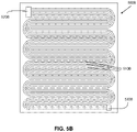
- FIG. 5B shows a similar serpentine flow field to FIG. 5A , but where the width of each serpentine flow channel decreases exponentially along its length.
- FIG. 6A is a simplified representation of a flow field plate comprising a flow channel that decreases exponentially in width for a first portion of the channel length and is then constant for a second portion of the channel
- FIG. 6B is a simplified representation of a flow field plate comprising a flow channel that is constant in width a first portion of the channel length and decreases exponentially for a second portion of the channel length.
- FIG. 7A is a simplified representation showing how 3 flow channels of the type shown in FIG. 6B can be arranged radially on an annular flow field plate.
- FIG. 7B is a simplified representation showing how multiple flow channels of the type shown in FIG. 6B can be arranged in a radial array on an annular flow field plate.
- FIG. 8 is a simplified representation of a flow field plate comprising two flow channels that are initially serpentine with constant width, and then the channel width decreases exponentially for a second portion of the channel length.
- FIG. 9 is a simplified representation of a flow field plate comprising a flow channel in which the channel depth is constant along a first portion of the channel length and then decreases along second a portion of the channel length.
- FIG. 10A shows a rectangular flow field plate comprising a multi-channel serpentine flow field extending between a supply and a discharge manifold opening.
- FIG. 10B shows a modification to the flow field plate of FIG. 10A , in which the width of each channel decreases exponentially along a middle portion of the length of each channel.
- FIG. 11 is a simplified representation of a flow field plate comprising a substantially rectangular flow channel having a central rib with exponentially curved side walls.
- FIG. 12A shows, in a simplified representation a flow field plate comprising a flow channel that has a conventional rectangular cross-section at one end and is gradually filleted to reduce its cross-section towards the other end, in the flow direction.
- FIG. 12B shows another view of the flow field plate of FIG. 12A .
- FIG. 13 is a simplified representation of a flow field plate comprising a rectangular flow channel incorporating rib dots, where density of the rib dots increases in the flow direction.
- FIG. 14 is a simplified representation of a flow field plate comprising a wavy flow channel incorporating rib dots, where density of the rib dots increases in the flow direction.
- FIG. 15 is a simplified representation illustrating an example where the flow channel width decreases in a stepwise, non-linear fashion in the flow direction.
- FIG. 16 is a simplified representation illustrating another example where the flow channel width decreases in a stepwise, non-linear fashion in the flow direction.
- FIG. 17 is a graphical representation illustrating how stepwise or discrete changes in channel width can be used to approximate e-flow.
- an anode flow field channel for a PEM fuel cell is designed for maintaining substantially constant fuel availability for the fuel cell electrochemical reaction along at least a portion of the length of the channel, for a given channel length and fuel stoichiometry, when the fuel cell is operating on either a pure or a dilute fuel stream.
- Hydrogen availability is a function of hydrogen mass flow and velocity, and is defined as follows:
- I d Current density (constant) [A/m 2 ]
- A(x) Cross-sectional area of channel at position x [m 2 ]
- ⁇ dot over (v) ⁇ fuel (x) Volumetric flow rate of fuel stream at position x [SLPM]
- the velocity of the fuel stream at a given position x along the channel is:
- Equation (1b) shows that increasing the hydrogen availability can be achieved by:
- equation (1b) shows that holding hydrogen availability constant along x requires changes in flow area.
- the flow area A(x) for each position along the channel length can be determined by solving equation (1b) for A(x) as shown in equation (7) below.
- the channel width and depth can be determined at any given lengthwise position x in the channel by defining area A(x) as the product of width W(x) and depth D(x), then changing the channel width or depth (W or D) along channel length x:
- An anode flow channel can be manufactured with a constant width and a varying depth profile to achieve constant hydrogen availability.
- Such a channel profile is calculated as follows:
- FIG. 1A is a simplified representation of an anode flow field plate 100 A comprising a flow channel 110 A that decreases in depth, with constant width, along its length.
- a channel profile can be defined by solving for D(x) in equation 4 at each position (x) along the length of the channel, given a specified operating fuel stoichiometry STOICH and channel length L, and assuming a constant channel width.
- the resulting anode channel 110 A extends between fuel supply manifold opening 120 A and discharge manifold opening 130 A, and has a linearly decreasing depth floor 112 A from inlet 116 A to outlet 118 A, with straight (parallel) side walls 114 A.
- the depth of the channel shallow. Therefore, instead of varying the depth of the channel, which would require a sufficiently thick plate to accommodate the deepest part of the channel, it can be preferred to keep the channel depth constant and to vary just the width of the channel to achieve constant hydrogen availability along the length of the channel.
- Equation (5) can be simplified to obtain
- FIG. 1B is a simplified representation of an anode flow field plate 100 B comprising a flow channel 110 B that decreases in width along its length.
- a channel profile can be defined by solving for W(x) in equation (6) at each position (x) along the length of the channel, given a specified operating fuel stoichiometry STOICH and channel length L, and assuming a flat channel floor (constant depth).
- the resulting anode channel 110 B extends between fuel supply manifold opening 120 B and discharge manifold opening 130 B, and has a constant depth floor 112 B with convexly curved side walls 114 B that converge inwards from inlet to outlet.
- the walls 114 B converge inwards towards an outlet end 118 B with an inlet 116 B having the largest width and the channel profile delineating at a diminishing rate. That is, the channel width decreases exponentially along the length of the channel from the inlet to the outlet according to the equation (6). It would be possible for one of the side walls to be straight and the other to be convexly curved.
- multiple channels 210 having the channel profile shown in FIG. 1B can be applied to a separator plate 200 , to form an anode flow field 222 extending between fuel supply manifold opening 220 and discharge manifold opening 230 .
- the anode flow field 222 is arrayed in a generally trapezoidal geometry to enable separating ribs 224 to have a relatively even width along their length; it can be seen that using a conventional rectangular flow field geometry with narrowing flow channels would require the ribs to also have a narrowing profile. Such a rib profile would result in significant amounts of MEA contacting the ribs, resulting in reduced membrane active area and less efficient usage of membrane material.
- MEA material is relatively expensive, it can be desirable to maximize the MEA active area using a generally even rib width.
- Using a generally trapezoidal flow field geometry also enables the flow field 222 to fit onto a trapezoidal separator plate 200 , or to fit onto a traditional rectangular separator plate with room to spare on the separator plate for other components such as manifolding (not shown).
- the separator plate 200 includes partial ribs 226 located at the inlet region of each channel 210 .
- the partial ribs 226 serve to reduce the distance between channel side walls, and serve as a bridging or support structure for the adjacent MEA (not shown).
- A(x) is then calculated through iteration based on channel profile.
- the resulting equation (7) encompasses various channel cross-sectional flow shapes that maintain a constant H 2 availability along the channel length.
- alternative channel cross-sectional profiles can include, but are not limited to: U-shaped channel, polygonal channel, semi-circular channel, varying fillet channel corner, varying chamfer channel corner, varying side wall slope angle channel, or varying floor bevel.
- a ⁇ ( x ) ( 1 . 3 ⁇ 5 ⁇ 1 ⁇ 0 - 1 ⁇ 4 ) ⁇ C ⁇ ⁇ f ⁇ u ⁇ e ⁇ l ⁇ ( ( I ⁇ Stoich ) - I d ⁇ ⁇ 0 x ⁇ W ⁇ ( x ) ⁇ d ⁇ x ) ⁇ ( I ⁇ Stoich ) AVAIL H ⁇ 2 ⁇ ( x ) ⁇ [ m 2 ] ( 7 )
- the preferred anode flow channel dimensions or characteristics based on the equations set forth above are applicable to operation on pure or dilute fuels as the equations take into account concentration (C).
- e-flow As used herein, the terms “e-flow”, “based on e-flow”, “based on the e-flow equations”, “in accordance with e-flow principles”, “e-flow channels”, and similar phrases are intended to refer to reactant flow channel dimensions, flow characteristics and/or flow field designs that are selected based on the equations and description set forth above with respect to the anode, and in U.S. Pat. No. 7,838,169 with respect to the cathode. Such channels or flow field designs can be incorporated into the anode and cathode flow field plates or other components of a fuel cell.
- Flow fields based on e-flow principles are more likely to be adopted if they can be accommodated within conventional flow field plate geometries and into conventional fuel cell stack architectures (which typically have rectangular flow field plates).
- Flow channels where the depth profile changes along the length of the channel can be accommodated by using the existing flow field design (pattern) and merely altering the depth profile of the channels along their length (keeping the channel width and ribs the same as in the original flow field design).
- plates with channels where the depth profile changes are generally more challenging to fabricate. They also result in a need for thicker plates, in order to accommodate the deepest part of the channel, leading to decreased fuel cell stack power density and higher cost.
- FIGS. 3-5 show some examples of ways in which flow fields based on e-flow where the flow channel width varies, can be applied to a rectangular reactant flow field plate.
- FIG. 3 shows a rectangular reactant flow field plate 300 with a serpentine channel 310 where the channel width is decreasing exponentially as it zig-zags across the plate between supply manifold opening 320 and discharge manifold opening 330 .
- FIG. 4A shows a rectangular reactant flow field plate 400 A with a wavy channel 410 A extending between supply manifold opening 420 A and discharge manifold opening 430 A, where the channel width is decreasing exponentially along its length.
- FIG. 3 shows a rectangular reactant flow field plate 300 with a serpentine channel 310 where the channel width is decreasing exponentially as it zig-zags across the plate between supply manifold opening 320 and discharge manifold opening 330 .
- FIG. 4A shows a rectangular reactant flow field plate 400 A with a wavy channel 410 A extending between supply man
- FIGS. 3 and 4A show a single flow channel, however, it is apparent that such channels can be repeated or arrayed across a rectangular plate so that a large portion of the plate area can be “active area” (for example, so that a large portion of the plate surface is covered in channels, with a large open channel area exposed to the adjacent electrode or MEA).
- FIG. 3 and 4A show a single flow channel, however, it is apparent that such channels can be repeated or arrayed across a rectangular plate so that a large portion of the plate area can be “active area” (for example, so that a large portion of the plate surface is covered in channels, with a large open channel area exposed to the adjacent electrode or MEA).
- FIG. 4B shows a rectangular reactant flow field plate 400 B with multiple flow channels 410 B (like flow channel 410 A of FIG. 4A repeated) extending between supply manifold opening 420 B and discharge manifold opening 430 B, arranged so that the channels nest together.
- This example describes a single direction array (x-axis shown) resulting in an overall approximately rectangular active area, and maintains substantially uniform rib width (channel spacing). This differs from a radial or arced array pattern resulting from maintaining substantially uniform rib width in the straight e-flow channel profile of FIG. 2 .
- FIG. 5A shows a square flow field plate 500 A comprising a conventional (prior art) serpentine flow field with three flow channels 510 A extending between supply manifold opening 520 A and discharge manifold opening 530 A.
- FIG. 5B shows a similar serpentine flow field plate 500 B, but where the width of each serpentine channel 510 B decreases exponentially along its length as it extends from supply manifold opening 520 B to discharge manifold opening 530 B.
- Another approach is to take a radial array of channels of decreasing width, such as is shown in FIG. 2 , and incorporate a 90° “fan” of such channels on a square plate with discharge manifold opening in one corner (where narrower ends of the channels converge) and supply manifold opening in the opposite corner, with a feed header extending along two sides of the square plate.
- a 180° fan of channels could be incorporated on a rectangular plate.
- Rectangular active area shapes are generally preferred for flow field plates (and other fuel cell components), as they generally make more efficient use of bulk sheet materials with less waste during manufacturing. It is possible to efficiently “nest” circular or trapezoidal plates onto a rectangular sheet, however there is generally more unused area than with rectangular cut shapes.
- Improvements in fuel cell performance can be obtained by incorporating e-flow along only a portion of the length of the reactant flow channel.
- the performance improvements are not necessarily as great as if e-flow is employed along the entire channel length, but such flow field designs can in some cases provide most of the benefit, and can allow more efficient use of the plate area.
- current density maps of conventional flow fields such as those having serpentine or straight flow channels, generally show reasonable uniformity of current density near the supply manifold followed by a reduction in current density further downstream. This indicates that e-flow can provide the most benefit if used in the latter portion of the channel length, where the current density is more sensitive to reactant availability.
- FIGS. 6-8 show some examples where the flow channel width varies along just a portion of the length of the channel.
- FIG. 6A shows a rectangular reactant flow field plate 600 A with a flow channel 610 A extending between supply manifold opening 620 A and discharge manifold opening 630 A.
- FIG. 6B shows a rectangular reactant flow field plate 600 B with a flow channel 610 B extending between supply manifold opening 620 B and discharge manifold opening 630 B.
- the flow channel width decreases exponentially for a first portion 625 A of the channel length (near the supply manifold), and is then constant for a second portion 635 A of the channel length (towards the discharge manifold).
- the flow channel width is constant for a first portion 625 B and decreases exponentially for a second portion 635 B of the channel length.
- FIGS. 7A & 7B show how flow channels 710 of the type shown in FIG. 6B can be arranged radially on an annular reactant flow field plate 700 .
- FIG. 7A is a partial view showing just a few channels 710
- FIG. 7B shows a complete flow field.
- FIG. 8 shows a reactant flow field plate 800 comprising two flow channels 810 .
- the channels are initially serpentine with constant width in portion 825 near the supply manifold opening 820 , and then, after abruptly increasing, the channel width decreases exponentially for a second portion 835 of the channel length (towards discharge manifold opening 830 ).
- FIG. 9 shows an example of a reactant flow field plate 900 comprising a flow channel 910 extending between a supply manifold opening 920 and a discharge manifold opening 930 .
- the flow channel depth is constant along a first portion 925 of the channel length and then decreases along a second portion 935 of the length of the channel 910 .
- the flow channels can incorporate an e-flow based variation in both width and depth along their entire length, or a portion of their length.
- FIGS. 10A & 10B illustrate how an existing flow field design can be readily modified to incorporate e-flow along a portion of the length of the flow channels.
- FIG. 10A shows a rectangular flow field plate 1000 A comprising a fairly complex serpentine flow field with multiple serpentine channels 1010 A extending between a supply and a discharge manifold opening.
- FIG. 10B shows a modification in which the width of each channel 1010 B decreases exponentially along a middle portion 1025 B of the length of each channel.
- FIG. 11 shows an example of a reactant flow field plate 1100 with a single flow channel 1110 extending between a supply manifold opening 1120 and a discharge manifold opening 1130 .
- the channel 1110 comprises a central rib 1140 with exponentially curved side walls. The rib splits the flow channel 1110 in two and effectively reduces its width gradually along most of its length in accordance with e-flow principles.
- FIGS. 12A and 12B show two different views of another example of a flow field plate 1200 with a single flow channel 1210 extending between a supply manifold opening 1220 and a discharge manifold opening 1230 .
- the channel 1210 is of a conventional rectangular cross-section at one end 1225 , and is gradually filleted to reduce its cross-section towards the other end 1235 , in accordance with e-flow principles.
- the flow channel dimensions vary along at least a portion of the channel length in a smooth and continuous fashion in accordance with e-flow principles.
- performance benefits can also be obtained by using reactant flow channels that incorporate a “discrete approximation” of e-flow.
- the characteristics of the channel can be varied as a function of distance along the channel in a stepwise or discontinuous fashion, but where the overall variation trends the smooth e-flow profile, either in fluctuations about the calculated profile, or in discrete approximations of the e-flow profile (so that it is in accordance with e-flow at a “macro” level).
- the channels can contain discrete features that obstruct reactant flow, where the density and/or size of those features increases in the flow direction.
- An example of a flow field plate 1300 where the flow channels incorporate rib dots or raised columns 1350 is shown in FIG. 13 .
- the density of the rib dots 1350 can increase in the reactant flow direction (indicated by the arrow) in accordance with the e-flow equations.
- FIG. 14 is a simplified representation of an anode flow field plate 1400 comprising a wavy flow channel 1410 incorporating rib dots 1450 , where the density of the rib dots increases in the flow direction (indicated by the arrow).
- the flow channel dimensions (for example, width or depth) can decrease in the flow direction in a stepwise fashion.
- the increments by which the channel dimensions change can be the same along the channel length, and in other embodiments it can vary along the channel length.
- the distance between (or frequency of) the step-changes in channel dimensions can be the same along the channel length, and in other embodiments it can vary along the channel length.
- FIGS. 15 and 16 illustrate examples where the channel width decreases in a stepwise, non-linear fashion in the flow direction in accordance with the e-flow equations.
- FIG. 15 is a simplified representation illustrating an example flow field plate 1500 where the width of flow channel 1510 decreases in a stepwise, non-linear fashion in the flow direction between a supply manifold opening 1520 and a discharge manifold opening 1530 .
- FIG. 16 is a simplified representation illustrating another example flow field plate 1600 where the width of flow channel 1610 decreases in a stepwise, non-linear fashion in the flow direction between a supply manifold opening 1620 and a discharge manifold opening 1630 .
- FIG. 17 is a graphical representation 1700 illustrating how stepwise or discrete changes in channel width can be used to approximate e-flow.
- the solid line 1710 represents changes in channel width and the dashed line 1720 shows a smooth exponential variation in channel width.
- the porosity of the flow channel could vary in a continuous or stepwise fashion in accordance with e-flow principles.
- FIGS. 1A, 1B, 3, 4A, 4B, 6A, 6B, 7A, 7B, 8, 9, 11, 12A, 12B, 13, 14, 15 and 16 are simplified drawings, in which the size of the flow channel and the manifold openings, and e-flow based variations in channel characteristics are exaggerated for the purposes of clear illustration.
- the flow characteristics of the flow channel vary along at least a portion of the channel length substantially in accordance with the e-flow equations.
- the variations can be continuous or discrete. In the latter case, a continuous curve fitted to the discrete changes would be substantially consistent with the e-flow equations.
- Flow channels with characteristics as described herein can be used at the anode or the cathode or both. Also they can be used for some or all of the fuel cells in a particular fuel cell stack.
- the open channel area versus the rib or landing area on a reactant flow field plate is generally selected to give sufficient electrical contact between the plates and the adjacent MEAs for efficient current collection, while providing sufficient reactant access to the electrodes of the MEA to support the electrochemical reactions.
- Using a wider rib area (between flow channels) improves electrical connectivity and current collection in the fuel cell.
- outlet refers to either the start of the flow channel where reactant enters the channel, or the start of a region where the channel characteristics vary as a function of channel length as described herein; and “outlet” refers to either the downstream end of the channel, or the end of a region over which channel characteristics vary as a function of channel length as described herein.
- Fuel cell flow field plates can utilize the reactant flow channels or flow field designs described above. Such plates can be made from suitable materials or combination of materials, and can be fabricated by suitable methods.
- Other fuel cell components can also incorporate the flow channels or passageways as described herein.
- such channels could be incorporated into the gas diffusion layer, or other components of the unit cell.
- Fuel cells and fuel cell stacks can also incorporate the flow field plates and/or other components.
- the reactant flow channels and flow field designs described herein have been found to be particularly advantageous in PEM fuel cells, however they can be applied in other types of fuel cells or other electrochemical devices, such as electrolyzers.
Landscapes
- Life Sciences & Earth Sciences (AREA)
- Engineering & Computer Science (AREA)
- Manufacturing & Machinery (AREA)
- Sustainable Development (AREA)
- Sustainable Energy (AREA)
- Chemical & Material Sciences (AREA)
- Chemical Kinetics & Catalysis (AREA)
- Electrochemistry (AREA)
- General Chemical & Material Sciences (AREA)
- Fuel Cell (AREA)
- Inert Electrodes (AREA)
Abstract
Description
where W(x) is the channel width at lengthwise position x, x is a selected position along the channel length [m], W(0) is the channel width at the fuel inlet, L is the channel length, and STOICH is the fuel stoichiometry of the fuel cell.
where A(x) is the channel cross-sectional area at lengthwise position x, x is a selected position along the channel length [m], C is the initial concentration of hydrogen (%), ρfuel is the fuel stream density [kg/m3], I is the entire channel current load [A], Id is the current density [A/m2], Stoich is fuel stoichiometry, W(x) is the width of channel at position x [m], and AVAILH2(x) is hydrogen availability at position x [kg·m/s2].
wherein,
-
- =Entire channel current load [A]
-
- 1. Uniform current density: an objective is to provide an anode flow channel that can achieve or approach uniform current density;
- 2. Single phase state (gas form): to reduce thermodynamic complexity, liquid water produced by the fuel cell reaction is considered to be the only fluid in liquid form; all other masses are considered to be in gas form;
- 3. Evenly distributed hydrogen concentration, velocity, and mass flow across flow section: complex flow patterns are not considered in the interest of reducing mass flow complexity;
- 4. Reaction is considered to be local to the flow channel only: the model does not consider above-rib activity (namely, in the region between channels where the MEA is in contact with plate, and is not directly exposed to fuel flowing in the flow channel);
- 5. Steady state system: the reaction and flows are considered to be steady state, or unchanging.
AVAILH2(x)={dot over (m)} H
{dot over (m)} H
Where {dot over (m)} H
Where {dot over (m)} H
{dot over (m)} H
Combining equations (2a) and (2b) then gives:
-
- Increasing current density (Id)
- Increasing fuel stoichiometry (Stoich)
- Increasing in channel length (L)
- Increasing average channel width (
W ) - Increasing fuel stream density (ρfuel)
- Decreasing channel depth (D)
Anode Flow Channel Having Varied Depth Profile
and solving for channel depth D(x):
The result is the depth profile is linear to x.
-
- increase in current density (Id);
- increase in fuel stoichiometry (Stoich);
- increase in channel length (L);
- increase in channel width (W);
- increase in fuel stream density (ρfuel); or,
- decrease in average depth (
D )
Anode Flow Channel Having Varied Width Profile
Solving for W(x), equation (5) is as follows:
Claims (20)
Priority Applications (3)
| Application Number | Priority Date | Filing Date | Title |
|---|---|---|---|
| US16/861,268 US11489175B2 (en) | 2012-08-14 | 2020-04-29 | Fuel cell flow channels and flow fields |
| US17/336,559 US20210310135A1 (en) | 2012-08-14 | 2021-06-02 | Reactant Flow Channels For Electrolyzer Applications |
| US17/949,872 US20230083155A1 (en) | 2012-08-14 | 2022-09-21 | Fuel Cell Flow Channels and Flow Fields |
Applications Claiming Priority (6)
| Application Number | Priority Date | Filing Date | Title |
|---|---|---|---|
| US201261683156P | 2012-08-14 | 2012-08-14 | |
| US201261712236P | 2012-10-10 | 2012-10-10 | |
| US201261712010P | 2012-10-10 | 2012-10-10 | |
| PCT/CA2013/050627 WO2014026288A1 (en) | 2012-08-14 | 2013-08-14 | Fuel cell flow channels and flow fields |
| US14/622,830 US10686199B2 (en) | 2012-08-14 | 2015-02-14 | Fuel cell flow channels and flow fields |
| US16/861,268 US11489175B2 (en) | 2012-08-14 | 2020-04-29 | Fuel cell flow channels and flow fields |
Related Parent Applications (1)
| Application Number | Title | Priority Date | Filing Date |
|---|---|---|---|
| US14/622,830 Continuation US10686199B2 (en) | 2012-08-14 | 2015-02-14 | Fuel cell flow channels and flow fields |
Related Child Applications (2)
| Application Number | Title | Priority Date | Filing Date |
|---|---|---|---|
| PCT/CA2013/050627 Continuation-In-Part WO2014026288A1 (en) | 2012-08-14 | 2013-08-14 | Fuel cell flow channels and flow fields |
| US17/949,872 Continuation US20230083155A1 (en) | 2012-08-14 | 2022-09-21 | Fuel Cell Flow Channels and Flow Fields |
Publications (2)
| Publication Number | Publication Date |
|---|---|
| US20200259188A1 US20200259188A1 (en) | 2020-08-13 |
| US11489175B2 true US11489175B2 (en) | 2022-11-01 |
Family
ID=50101161
Family Applications (3)
| Application Number | Title | Priority Date | Filing Date |
|---|---|---|---|
| US14/622,830 Active US10686199B2 (en) | 2012-08-14 | 2015-02-14 | Fuel cell flow channels and flow fields |
| US16/861,268 Active 2033-09-07 US11489175B2 (en) | 2012-08-14 | 2020-04-29 | Fuel cell flow channels and flow fields |
| US17/949,872 Abandoned US20230083155A1 (en) | 2012-08-14 | 2022-09-21 | Fuel Cell Flow Channels and Flow Fields |
Family Applications Before (1)
| Application Number | Title | Priority Date | Filing Date |
|---|---|---|---|
| US14/622,830 Active US10686199B2 (en) | 2012-08-14 | 2015-02-14 | Fuel cell flow channels and flow fields |
Family Applications After (1)
| Application Number | Title | Priority Date | Filing Date |
|---|---|---|---|
| US17/949,872 Abandoned US20230083155A1 (en) | 2012-08-14 | 2022-09-21 | Fuel Cell Flow Channels and Flow Fields |
Country Status (5)
| Country | Link |
|---|---|
| US (3) | US10686199B2 (en) |
| CN (3) | CN107591549B (en) |
| CA (2) | CA3123208C (en) |
| GB (1) | GB2519494B (en) |
| WO (1) | WO2014026288A1 (en) |
Families Citing this family (27)
| Publication number | Priority date | Publication date | Assignee | Title |
|---|---|---|---|---|
| CN107591549B (en) | 2012-08-14 | 2020-12-01 | 环能源公司 | Fuel cell flow channel and flow field |
| GB201503750D0 (en) | 2012-08-14 | 2015-04-22 | Powerdisc Dev Corp Ltd | Fuel cells components, stacks and modular fuel cell systems |
| US9644277B2 (en) | 2012-08-14 | 2017-05-09 | Loop Energy Inc. | Reactant flow channels for electrolyzer applications |
| DE102014206682A1 (en) | 2014-04-07 | 2015-10-08 | Volkswagen Aktiengesellschaft | Bipolar plate and fuel cell |
| CA3016102A1 (en) | 2016-03-22 | 2017-09-28 | Loop Energy Inc. | Fuel cell flow field design for thermal management |
| JP6354797B2 (en) | 2016-06-24 | 2018-07-11 | トヨタ自動車株式会社 | Fuel cell single cell |
| KR102140126B1 (en) * | 2016-11-14 | 2020-07-31 | 주식회사 엘지화학 | Separator for fuel cell and fuel cell using the same |
| JP6672193B2 (en) * | 2017-02-02 | 2020-03-25 | 株式会社東芝 | Carbon dioxide electrolysis cell and electrolyzer |
| JP7021551B2 (en) * | 2018-02-08 | 2022-02-17 | トヨタ自動車株式会社 | Fuel cell stack |
| CN109390603A (en) * | 2018-11-15 | 2019-02-26 | 华南理工大学 | A kind of ripple flow-field plate |
| CN109616685A (en) * | 2018-12-11 | 2019-04-12 | 中国科学院大连化学物理研究所 | A kind of fuel cell bipolar plate structure |
| FR3091627B1 (en) | 2019-01-07 | 2021-07-23 | Commissariat Energie Atomique | ELECTROCHEMICAL CELL MAINTAINING PLATE WITH AN OPTIMIZED FLUID DISTRIBUTION NETWORK |
| JP7202226B2 (en) | 2019-03-13 | 2023-01-11 | 株式会社豊田中央研究所 | fuel cell system |
| CN110165242B (en) * | 2019-05-05 | 2022-06-03 | 武汉理工大学 | PEM battery flow field plate structure with multi-layer flow channel width |
| JP7136030B2 (en) * | 2019-07-19 | 2022-09-13 | トヨタ車体株式会社 | fuel cell stack |
| CN110690488A (en) * | 2019-11-13 | 2020-01-14 | 上海海事大学 | Flow battery |
| CN112909286B (en) * | 2019-12-03 | 2023-01-24 | 未势能源科技有限公司 | Polar plate and fuel cell |
| US11404705B2 (en) * | 2020-08-13 | 2022-08-02 | Seoul National University R&Db Foundation | Bipolar plate of polymer electrolyte membrane fuel cell |
| CN112133937B (en) * | 2020-09-01 | 2021-09-07 | 山东大学 | Proton exchange membrane fuel cell runner structure and proton exchange membrane fuel cell |
| TW202249331A (en) | 2021-03-22 | 2022-12-16 | 丹麥商托普索公司 | Soec stack with fuel flow from periphery towards centre |
| CN112952134B (en) * | 2021-04-07 | 2023-02-03 | 上海交通大学 | Cathode flow field structure of longitudinal and transverse reversible fuel cell |
| KR20230169219A (en) * | 2021-04-10 | 2023-12-15 | 루프 에너지 인크. | Fuel cell assembly having fuel cell plate with reduced and/or eliminated transition zone |
| US20220384819A1 (en) * | 2021-05-27 | 2022-12-01 | Toyota Boshoku Kabushiki Kaisha | Separator for fuel cell |
| US20240243303A1 (en) * | 2021-06-04 | 2024-07-18 | Hydrogenics Corporation | Non-uniform reactant channels in bipolar plates for fuel cells |
| CN113809350B (en) * | 2021-08-30 | 2023-10-17 | 一汽解放汽车有限公司 | Fuel cell and cell unit |
| CN114094135B (en) * | 2021-10-10 | 2023-06-09 | 北京工业大学 | Liquid water self-adaptive flow field plate of fuel cell capable of automatically switching parallel flow field and serpentine flow field |
| CN114725424A (en) * | 2022-06-08 | 2022-07-08 | 爱德曼氢能源装备有限公司 | Radial flow field structure of fuel cell |
Citations (167)
| Publication number | Priority date | Publication date | Assignee | Title |
|---|---|---|---|---|
| US4324844A (en) | 1980-04-28 | 1982-04-13 | Westinghouse Electric Corp. | Variable area fuel cell cooling |
| US4407904A (en) | 1981-02-20 | 1983-10-04 | Hitachi, Ltd. | Fuel cell |
| US4490445A (en) | 1982-05-24 | 1984-12-25 | Massachusetts Institute Of Technology | Solid oxide electrochemical energy converter |
| JPS61256568A (en) | 1985-05-09 | 1986-11-14 | Toshiba Corp | Fuel cell |
| EP0207799A2 (en) | 1985-07-03 | 1987-01-07 | Westinghouse Electric Corporation | Improved coolant passage structure for rotor blades in a combustion turbine |
| US4770955A (en) | 1987-04-28 | 1988-09-13 | The Standard Oil Company | Solid electrolyte fuel cell and assembly |
| US4910100A (en) | 1989-07-21 | 1990-03-20 | Fuji Electric Co., Ltd. | Solid electrolyte fuel cell |
| US4953634A (en) | 1989-04-20 | 1990-09-04 | Microelectronics And Computer Technology Corporation | Low pressure high heat transfer fluid heat exchanger |
| JPH03276569A (en) | 1990-03-26 | 1991-12-06 | Fuji Electric Co Ltd | Fuel cell |
| JPH04370664A (en) | 1991-06-19 | 1992-12-24 | Ishikawajima Harima Heavy Ind Co Ltd | Fuel cell |
| EP0355420B1 (en) | 1988-07-23 | 1993-10-06 | Fuji Electric Co., Ltd. | Solid electrolyte fuel cell |
| US5338622A (en) | 1993-04-12 | 1994-08-16 | Ztek Corporation | Thermal control apparatus |
| EP0616380A1 (en) | 1993-03-16 | 1994-09-21 | FINMECCANICA S.p.A. AZIENDA ANSALDO | A gas distributor for fused carbonates-fuel cells |
| JPH06267564A (en) | 1993-03-15 | 1994-09-22 | Mitsubishi Heavy Ind Ltd | Solid high polymer electrolyte fuel cell |
| US5399442A (en) | 1993-02-08 | 1995-03-21 | Fuji Electric Co., Ltd. | Solid electrolyte fuel cell |
| US5514486A (en) | 1995-09-01 | 1996-05-07 | The Regents Of The University Of California, Office Of Technology Transfer | Annular feed air breathing fuel cell stack |
| US5527634A (en) | 1992-02-20 | 1996-06-18 | Electric Power Research Institute, Inc. | Multiple manifold fuel cell |
| US5549983A (en) | 1996-01-22 | 1996-08-27 | Alliedsignal Inc. | Coflow planar fuel cell stack construction for solid electrolytes |
| US5589285A (en) | 1993-09-09 | 1996-12-31 | Technology Management, Inc. | Electrochemical apparatus and process |
| US5595834A (en) | 1995-09-01 | 1997-01-21 | The Regents Of The University Of Calif. | Annular feed air breathing fuel cell stack |
| JPH0950817A (en) | 1995-08-03 | 1997-02-18 | Sanyo Electric Co Ltd | Fuel cell |
| US5851689A (en) | 1997-01-23 | 1998-12-22 | Bechtel Corporation | Method for operating a fuel cell assembly |
| JPH1116590A (en) | 1997-06-26 | 1999-01-22 | Matsushita Electric Ind Co Ltd | Fuel cell |
| US6048633A (en) | 1998-03-02 | 2000-04-11 | Honda Giken Kogyo Kabushiki Kaisha | Fuel cell stack |
| WO2000026981A2 (en) | 1998-10-29 | 2000-05-11 | 3M Innovative Properties Company | Microstructured flow fields |
| US6161610A (en) | 1996-06-27 | 2000-12-19 | Azar; Kaveh | Heat sink with arc shaped fins |
| JP2001006717A (en) | 1999-06-25 | 2001-01-12 | Toshiba Corp | Fuel cell device and electric apparatus mounted with fuel cell |
| AT407589B (en) | 1999-11-03 | 2001-04-25 | Vaillant Gmbh | Fuel cell |
| US6234245B1 (en) | 1998-07-02 | 2001-05-22 | Fintube Technologies, Inc. | Aero curve fin segment |
| US6245453B1 (en) | 1997-12-18 | 2001-06-12 | Toyota Jidosha Kabushiki Kaisha | Fuel cell and separator for the same |
| US20010003309A1 (en) | 1998-05-18 | 2001-06-14 | Stephen G. Adrian | Heat exchanger |
| US6253835B1 (en) | 2000-02-11 | 2001-07-03 | International Business Machines Corporation | Isothermal heat sink with converging, diverging channels |
| US6258474B1 (en) | 1997-11-25 | 2001-07-10 | Sulzer Hexis Ag | Fuel cell module with an integrated additional heater |
| US6291089B1 (en) | 1999-10-26 | 2001-09-18 | Alliedsignal Inc. | Radial planar fuel cell stack construction for solid electrolytes |
| JP2001291522A (en) | 2000-04-10 | 2001-10-19 | Araco Corp | Fuel cell |
| US6337794B1 (en) | 2000-02-11 | 2002-01-08 | International Business Machines Corporation | Isothermal heat sink with tiered cooling channels |
| US20020012463A1 (en) | 2000-06-09 | 2002-01-31 | Fuji Photo Film Co., Ltd. | Apparatus and method for acquiring images using a solid-state image sensor and recording medium having recorded thereon a program for executing the method |
| US6344290B1 (en) | 1997-02-11 | 2002-02-05 | Fucellco, Incorporated | Fuel cell stack with solid electrolytes and their arrangement |
| US20020017463A1 (en) | 2000-06-05 | 2002-02-14 | Merida-Donis Walter Roberto | Method and apparatus for integrated water deionization, electrolytic hydrogen production, and electrochemical power generation |
| US6406809B1 (en) | 1999-02-09 | 2002-06-18 | Honda Giken Kogyo Kabushiki Kaisha | Fuel cell comprising a separator provided with coolant passages |
| US6423437B1 (en) | 2001-01-19 | 2002-07-23 | Enable Fuel Cell Corporation | Passive air breathing fuel cells |
| WO2002065565A2 (en) | 2001-02-12 | 2002-08-22 | The Morgan Crucible Company Plc | Flow field plate geometries |
| CA2437892A1 (en) | 2001-02-12 | 2002-08-22 | The Morgan Crucible Company Plc | Flow field plate geometries |
| CA2441087A1 (en) | 2001-04-11 | 2002-10-24 | Donaldson Company, Inc. | Filter assemblies and systems for intake air for fuel cells |
| WO2002089244A1 (en) | 2001-04-27 | 2002-11-07 | Enable Fuel Cell Corporation | Passive air breathing fuel cell system with switched fuel gas delivery |
| US6528196B1 (en) | 1999-08-13 | 2003-03-04 | Honda Giken Kogyo Kabushiki Kaisha | Fuel cell stack having bent section flow passage grooves |
| US20030041444A1 (en) | 1997-10-10 | 2003-03-06 | 3M Innovative Properties Company | Membrane electrode assemblies |
| US20030059662A1 (en) | 2001-09-17 | 2003-03-27 | 3M Innovative Properties Company | Flow field |
| JP2003092121A (en) | 2001-09-14 | 2003-03-28 | Toyota Motor Corp | Fuel cell |
| US6551736B1 (en) | 2000-10-30 | 2003-04-22 | Teledyne Energy Systems, Inc. | Fuel cell collector plates with improved mass transfer channels |
| US20030077501A1 (en) | 2001-10-23 | 2003-04-24 | Ballard Power Systems Inc. | Electrochemical fuel cell with non-uniform fluid flow design |
| US6586128B1 (en) | 2000-05-09 | 2003-07-01 | Ballard Power Systems, Inc. | Differential pressure fluid flow fields for fuel cells |
| US20030134174A1 (en) | 2000-12-28 | 2003-07-17 | Jun Akikusa | Fuel cell module and structure for gas supply to fuel cell |
| US20030186106A1 (en) | 2001-05-15 | 2003-10-02 | David Frank | Fuel cell flow field plate |
| US6663992B2 (en) | 2000-02-20 | 2003-12-16 | General Motors Corporation | Cooling rib arrangement for the equalization of the temperature distribution in air cooled stacks |
| US6664693B2 (en) | 2000-12-19 | 2003-12-16 | Powerdisc Development Corporation Ltd. | Fuel cell powered electrical motor |
| US6686082B2 (en) | 2000-12-11 | 2004-02-03 | Powerdisc Development Corp. Ltd. | Fuel cell stack |
| US6699614B2 (en) | 2002-03-18 | 2004-03-02 | General Motors Corporation | Converging/diverging flow channels for fuel cell |
| US20040067405A1 (en) | 2001-02-12 | 2004-04-08 | Turpin Mark Christopher | Flow field plate geometries |
| US6722422B1 (en) | 2003-06-10 | 2004-04-20 | Feldmeier Equipment, Inc. | Heat exchange system with improved flow velocity adjustment mechanism |
| US6729383B1 (en) | 1999-12-16 | 2004-05-04 | The United States Of America As Represented By The Secretary Of The Navy | Fluid-cooled heat sink with turbulence-enhancing support pins |
| US20040099045A1 (en) | 2002-11-26 | 2004-05-27 | Proton Energy Systems | Combustible gas detection systems and method thereof |
| US20040142225A1 (en) | 2001-05-03 | 2004-07-22 | Turpin Mark Christopher | Fuel cell or electrolyser construction |
| US6773843B2 (en) | 2001-03-09 | 2004-08-10 | Daido Metal Company Ltd. | Portable fuel cell stack |
| CA2456731A1 (en) | 2003-02-13 | 2004-08-13 | Toyota Jidosha Kabushiki Kaisha | Separator passage structure of fuel cell |
| WO2004114446A1 (en) | 2003-06-18 | 2004-12-29 | The Morgan Crucible Company Plc | Flow field plate geometries |
| EP1496558A1 (en) | 2003-07-11 | 2005-01-12 | Asia Pacific Fuel Cell Technologies, Ltd. | Water draining structure for gas reaction plate of fuel cell stack |
| US6849353B2 (en) | 2002-03-29 | 2005-02-01 | General Electric Company | Polygonal fuel cell apparatus and method of making |
| US20050026022A1 (en) | 2003-06-25 | 2005-02-03 | Joos Nathaniel Ian | Passive electrode blanketing in a fuel cell |
| US20050081552A1 (en) | 2003-10-09 | 2005-04-21 | Robert Nilson | Axially tapered and bilayer microchannels for evaporative coolling devices |
| US20050087326A1 (en) | 2003-10-22 | 2005-04-28 | Felix Barmoav | Heat sinks |
| US20050112428A1 (en) | 2003-10-23 | 2005-05-26 | Hydrogenics Corporation | Fuel cell power system having multiple fuel cell modules |
| US20050115825A1 (en) | 2003-09-22 | 2005-06-02 | David Frank | Electrolyzer cell arrangement |
| US6903931B2 (en) | 2002-06-13 | 2005-06-07 | Raytheon Company | Cold plate assembly |
| US20050123821A1 (en) | 2003-11-05 | 2005-06-09 | Al-Qattan Ayman M. | Distributed feed fuel cell stack |
| US20050142425A1 (en) | 2003-12-26 | 2005-06-30 | Honda Motor Co., Ltd. | Fuel cell can fuel cell stack |
| US6921598B2 (en) | 2000-03-07 | 2005-07-26 | Matsushita Electric Industrial Co., Ltd. | Polymer electrolyte fuel cell and method of manufacturing the same |
| CN1663067A (en) | 2002-06-24 | 2005-08-31 | 摩根坩埚有限公司 | Flow field plate geometries |
| JP2005268110A (en) | 2004-03-19 | 2005-09-29 | Mitsubishi Electric Corp | Fuel cell separator |
| JP2005536033A (en) | 2002-08-13 | 2005-11-24 | ダイムラークライスラー・アクチェンゲゼルシャフト | Control of fluid flow in electrochemical cells |
| US20050271909A1 (en) | 2004-06-07 | 2005-12-08 | Hyteon Inc. | Flow field plate for use in fuel cells |
| US7008712B2 (en) | 2002-03-22 | 2006-03-07 | Daido Metal Company Ltd. | Split cell type fuel cell stack |
| US20060093891A1 (en) | 2004-11-02 | 2006-05-04 | General Electric Company | Flow field design for high fuel utilization fuel cells |
| KR20060059461A (en) | 2004-11-29 | 2006-06-02 | 삼성에스디아이 주식회사 | Fuel cell system and stack of the same |
| US20060154125A1 (en) | 2005-01-10 | 2006-07-13 | Young-Seung Na | Stack for fuel cell and fuel cell system with the same |
| CA2880560A1 (en) | 2005-01-05 | 2006-07-13 | Powerdisc Development Corporation Ltd. | Fuel cell system with cathode flow field variation |
| EP1410455B1 (en) | 2001-07-25 | 2006-08-30 | Ballard Power Systems Inc. | Fuel cell system having a hydrogen sensor |
| US7108929B2 (en) | 2003-09-22 | 2006-09-19 | Utc Fuel Cells, Llc | Fuel and air flow control in a multi-stack fuel cell power plant |
| US20060234107A1 (en) | 2002-05-03 | 2006-10-19 | Leger David E | Fuel cell plates and assemblies |
| US20060257704A1 (en) | 2003-11-28 | 2006-11-16 | Toyota Jidosha Kabushiki Kaisha | Fuel cell |
| WO2006120027A1 (en) | 2005-05-13 | 2006-11-16 | Ashe Morris Ltd | Heat exchanger with varying cross sectional area of conduits |
| US7138200B1 (en) | 1997-12-18 | 2006-11-21 | Toyota Jidosha Kabushiki Kaisha | Fuel cell and separator for the same |
| US20070009781A1 (en) | 2005-04-22 | 2007-01-11 | Byd Company Limited | Flow field plates for fuel cells |
| US20070099062A1 (en) | 2005-10-28 | 2007-05-03 | Andrei Leonida | Fuel cell system suitable for complex fuels and a method of operation of the same |
| US20070105000A1 (en) | 2003-06-18 | 2007-05-10 | The Morgan Crucible Company Plc | Flow field plate geometries |
| US20070178359A1 (en) | 2006-01-27 | 2007-08-02 | Samsung Sdi Co., Ltd. | Bipolar plate for fuel cell |
| US20070289718A1 (en) | 2006-06-06 | 2007-12-20 | Mccordic Craig H | Heat sink and method of making same |
| US7316853B2 (en) | 2002-07-05 | 2008-01-08 | Daido Metal Company Ltd. | Airbreathing fuel cell |
| US20080008916A1 (en) | 2006-07-10 | 2008-01-10 | Samsung Sdi Co., Ltd. | Cooling plate having improved flow channels |
| JP2008010179A (en) | 2006-06-27 | 2008-01-17 | Toyota Motor Corp | Fuel cell separator |
| US20080070080A1 (en) | 2004-12-16 | 2008-03-20 | Nissan Motor Co., Ltd. | Fuel Cell Separator |
| US20080066888A1 (en) | 2006-09-08 | 2008-03-20 | Danaher Motion Stockholm Ab | Heat sink |
| US7348094B2 (en) | 2004-12-10 | 2008-03-25 | Gm Global Technology Operations, Inc. | Enhanced flowfield plates |
| US20080096083A1 (en) | 2006-10-18 | 2008-04-24 | Yean-Der Kuan | Assembly structre for fuel cell stacks and fan |
| JP2008103168A (en) | 2006-10-18 | 2008-05-01 | Honda Motor Co Ltd | Fuel cell |
| JP2008108571A (en) | 2006-10-25 | 2008-05-08 | Toyota Motor Corp | Separator and fuel cell |
| US20080107946A1 (en) | 2006-11-08 | 2008-05-08 | Akira Gunji | Fuel cells power generation system |
| EP1512192B1 (en) | 2002-03-28 | 2008-05-21 | Intelligent Energy Limited | Fuel cell compression assembly |
| US20080135402A1 (en) | 2006-12-06 | 2008-06-12 | General Electric Company | Gas evolving electrolysis system |
| US7399547B2 (en) | 2004-11-05 | 2008-07-15 | Utc Fuel Cells, Llc | Fuel and air flow control in a multi-stack fuel cell power plant |
| US7410714B1 (en) | 2004-07-15 | 2008-08-12 | The United States Of America As Represented By The Administration Of Nasa | Unitized regenerative fuel cell system |
| CN101253645A (en) | 2005-10-11 | 2008-08-27 | 丰田自动车株式会社 | Gas separator for fuel cell and fuel cell |
| US20080248371A1 (en) | 2007-04-03 | 2008-10-09 | Yuan Ze University | Fuel cell with a passage structure |
| US20080248367A1 (en) | 2007-04-03 | 2008-10-09 | Yuan Ze University | Fuel cell module compatible with a dry cell |
| US7459227B2 (en) | 2003-04-18 | 2008-12-02 | General Motors Corporation | Stamped fuel cell bipolar plate |
| US20080311461A1 (en) | 2007-06-18 | 2008-12-18 | Simon Farrington | Electrochemical fuel cell stack having staggered fuel and oxidant plenums |
| US20090035616A1 (en) | 2004-12-29 | 2009-02-05 | Utc Power Corporation | Full cells evaporative cooling and combined evaporative and sensible cooling |
| US20090053570A1 (en) | 2006-04-26 | 2009-02-26 | Tian Binglun | Fuel cell stack for low temperature start-up and operation |
| US20090081516A1 (en) | 2006-09-15 | 2009-03-26 | Toto Ltd. | Fuel cell body, fuel cell unit, fuel cell stack, and fuel cell device including each of them |
| JP2009081061A (en) | 2007-09-26 | 2009-04-16 | Honda Motor Co Ltd | Fuel cell |
| US20090145581A1 (en) | 2007-12-11 | 2009-06-11 | Paul Hoffman | Non-linear fin heat sink |
| CA2653148A1 (en) | 2008-02-19 | 2009-08-19 | Bdf Ip Holdings Ltd. | Flow field for fuel cell and fuel cell stack |
| US7593230B2 (en) | 2005-05-05 | 2009-09-22 | Sensys Medical, Inc. | Apparatus for absorbing and dissipating excess heat generated by a system |
| US7601452B2 (en) | 2003-09-12 | 2009-10-13 | Gm Global Technology Operations, Inc. | Nested bipolar plate for fuel cell and method |
| US20090258256A1 (en) | 2008-04-11 | 2009-10-15 | Limbeck Uwe M | System and method of starting a fuel cell system |
| EP2113731A1 (en) | 2008-04-30 | 2009-11-04 | ABB Research LTD | Heat exchanger device |
| US7615308B2 (en) | 2004-03-03 | 2009-11-10 | Ird Fuel Cells A/S | Dual function, bipolar separator plates for fuel cells |
| US7618734B2 (en) | 2004-05-19 | 2009-11-17 | General Motors Corporation | Branched fluid channels for improved fluid flow through fuel cell |
| US20100119909A1 (en) | 2008-11-11 | 2010-05-13 | Bloom Energy Corporation | Fuel cell interconnect |
| US7718298B2 (en) | 2007-03-12 | 2010-05-18 | Gm Global Technology Operations, Inc. | Bifurcation of flow channels in bipolar plate flowfields |
| US20100178581A1 (en) | 2009-01-14 | 2010-07-15 | Samsung Sdi Co., Ltd. | Fuel cell stack and fuel cell system using the same |
| US20100190087A1 (en) | 2007-09-19 | 2010-07-29 | Yuichi Yoshida | Fuel cell |
| US20100203399A1 (en) | 2009-02-06 | 2010-08-12 | Protonex Technology Corporation | Solid oxide fuel cell systems with hot zones having improved reactant distribution |
| US20100216044A1 (en) | 2009-02-20 | 2010-08-26 | Clearedge Power, Inc. | Air-Cooled Thermal Management for a Fuel Cell Stack |
| US20100279189A1 (en) | 2007-03-09 | 2010-11-04 | Coretronic Corporation | Fuel cell system |
| US7883813B2 (en) | 2006-04-03 | 2011-02-08 | Bloom Energy Corporation | Fuel cell system ventilation scheme |
| WO2011028389A2 (en) | 2009-09-04 | 2011-03-10 | Raytheon Company | Heat transfer device |
| US20110076585A1 (en) | 2009-09-30 | 2011-03-31 | Bloom Energy Corporation | Fuel Cell Stack Compression Devices and Methods |
| US20110079370A1 (en) | 2009-07-17 | 2011-04-07 | Textron Inc. | Non-Uniform Height And Density Fin Design For Heat Sink |
| CN102035002A (en) | 2010-11-30 | 2011-04-27 | 新源动力股份有限公司 | Fuel cell module with water and thermal management capability |
| CN102089911A (en) | 2008-07-15 | 2011-06-08 | 戴姆勒股份公司 | Bipolar plate for a fuel cell arrangement, in particular for placement between two adjacent membrane electrode arrangements |
| US20110171023A1 (en) | 2009-10-20 | 2011-07-14 | Ching-Pang Lee | Airfoil incorporating tapered cooling structures defining cooling passageways |
| US20110171551A1 (en) | 2008-09-19 | 2011-07-14 | Mtu Onsite Energy Gmbh | Fuel cell assembly with a modular construction |
| US20110177417A1 (en) | 2010-01-15 | 2011-07-21 | 4D Power, LLC | Fuel cell stack system having multiple sub-stacks that are replaceable online |
| CA2787467A1 (en) | 2010-01-25 | 2011-07-28 | Ramot At Tel-Aviv University Ltd | Bipolar plates of a regenerative fuel cell stack assembly having flow field designs and shunt current suppression channels |
| US20110223508A1 (en) | 2010-03-14 | 2011-09-15 | Philip Mark Arnold | Proton exchange membrane (pem) fuel cell |
| US20110223507A1 (en) | 2010-03-10 | 2011-09-15 | Idatech, Llc | Systems and methods for fuel cell thermal management |
| US8026020B2 (en) | 2007-05-08 | 2011-09-27 | Relion, Inc. | Proton exchange membrane fuel cell stack and fuel cell stack module |
| US8026013B2 (en) | 2006-08-14 | 2011-09-27 | Modine Manufacturing Company | Annular or ring shaped fuel cell unit |
| US20110232885A1 (en) | 2010-03-26 | 2011-09-29 | Kaslusky Scott F | Heat transfer device with fins defining air flow channels |
| US20110262826A1 (en) | 2010-04-22 | 2011-10-27 | GM Global Technology Operations LLC | Formed plate assembly for pem fuel cell |
| US20110269037A1 (en) | 2008-09-19 | 2011-11-03 | Mtu Onsite Energy Gmbh | Fuel cell assembly comprising an improved catalytic burner |
| US20120040260A1 (en) | 2009-04-28 | 2012-02-16 | Panasonic Corporation | Fuel cell system and water draining method for fuel cell system |
| US8157527B2 (en) | 2008-07-03 | 2012-04-17 | United Technologies Corporation | Airfoil with tapered radial cooling passage |
| US20120107714A1 (en) | 2010-09-20 | 2012-05-03 | Day Michael J | Fuel cell repeat unit and fuel cell stack |
| CN102623730A (en) | 2012-04-20 | 2012-08-01 | 上海电机学院 | Variable-runner low-temperature and low-voltage rectangular fuel cell |
| JP5029813B2 (en) | 2007-03-20 | 2012-09-19 | トヨタ自動車株式会社 | Fuel cell separator |
| US20130149625A1 (en) | 2010-08-31 | 2013-06-13 | Suzuki Motor Corporation | Fuel cell system |
| US20130252116A1 (en) | 2012-03-21 | 2013-09-26 | GM Global Technology Operations LLC | Model Based Approach For In-Situ WVTD Degradation Detection In Fuel Cell Vehicles |
| WO2014056110A1 (en) | 2012-10-10 | 2014-04-17 | Powerdisc Development Corporation Ltd. | Reactant flow channels for electrolyzer applications |
| US20140193738A1 (en) | 2012-12-10 | 2014-07-10 | Commissariat A L'energie Atomique Et Aux Energies Alternatives | Cell for fuel-cell battery using a proton exchange membrane, with gas diffusion layers of different rigidity at the anode and at the cathode |
| US20140329164A1 (en) | 2011-12-26 | 2014-11-06 | Toray Industries, Inc. | Gas diffusion medium for fuel cell, membrane electrode assembly, and fuel cell |
| CN104718651A (en) | 2012-08-14 | 2015-06-17 | 动力盘开发有限公司 | Fuel cell flow channels and flow fields |
| US20150180079A1 (en) | 2012-08-14 | 2015-06-25 | Powerdisc Development Corporation Ltd. | Fuel Cell Components, Stacks and Modular Fuel Cell Systems |
| US20150349353A1 (en) | 2012-12-27 | 2015-12-03 | Intelligent Energy Limited | Fluid flow plate for a fuel cell |
| US9644277B2 (en) | 2012-08-14 | 2017-05-09 | Loop Energy Inc. | Reactant flow channels for electrolyzer applications |
| WO2019046108A2 (en) | 2017-08-28 | 2019-03-07 | Ballard Power Systems Inc. | Flow field plate for electrochemical fuel cells |
Family Cites Families (6)
| Publication number | Priority date | Publication date | Assignee | Title |
|---|---|---|---|---|
| US4517229A (en) | 1983-07-07 | 1985-05-14 | Inland Steel Company | Diffusion treated hot-dip aluminum coated steel and method of treating |
| JP2002319551A (en) | 2001-04-23 | 2002-10-31 | Nec Corp | Semiconductor device and its manufacturing method |
| US7205062B2 (en) * | 2002-11-22 | 2007-04-17 | The Research Foundation Of State University Of New York | Fuel cell stack |
| US7083079B2 (en) * | 2003-07-09 | 2006-08-01 | Moore Wallace North America, Inc. | Double postcard pressure seal form construction |
| US20080021364A1 (en) * | 2006-07-17 | 2008-01-24 | Industrial Technology Research Institute | Fluidic device |
| WO2011114702A1 (en) * | 2010-03-17 | 2011-09-22 | パナソニック株式会社 | Polymer electrolyte fuel cell and fuel cell stack equipped with same |
-
2013
- 2013-08-14 CN CN201710699589.2A patent/CN107591549B/en active Active
- 2013-08-14 CA CA3123208A patent/CA3123208C/en active Active
- 2013-08-14 CN CN201380053699.1A patent/CN104718651B/en active Active
- 2013-08-14 GB GB1503751.8A patent/GB2519494B/en active Active
- 2013-08-14 WO PCT/CA2013/050627 patent/WO2014026288A1/en active Application Filing
- 2013-08-14 CN CN201710699586.9A patent/CN107579263B/en active Active
- 2013-08-14 CA CA2919875A patent/CA2919875C/en active Active
-
2015
- 2015-02-14 US US14/622,830 patent/US10686199B2/en active Active
-
2020
- 2020-04-29 US US16/861,268 patent/US11489175B2/en active Active
-
2022
- 2022-09-21 US US17/949,872 patent/US20230083155A1/en not_active Abandoned
Patent Citations (194)
| Publication number | Priority date | Publication date | Assignee | Title |
|---|---|---|---|---|
| US4324844A (en) | 1980-04-28 | 1982-04-13 | Westinghouse Electric Corp. | Variable area fuel cell cooling |
| US4407904A (en) | 1981-02-20 | 1983-10-04 | Hitachi, Ltd. | Fuel cell |
| US4490445A (en) | 1982-05-24 | 1984-12-25 | Massachusetts Institute Of Technology | Solid oxide electrochemical energy converter |
| JPS61256568A (en) | 1985-05-09 | 1986-11-14 | Toshiba Corp | Fuel cell |
| EP0207799A2 (en) | 1985-07-03 | 1987-01-07 | Westinghouse Electric Corporation | Improved coolant passage structure for rotor blades in a combustion turbine |
| US4770955A (en) | 1987-04-28 | 1988-09-13 | The Standard Oil Company | Solid electrolyte fuel cell and assembly |
| EP0355420B1 (en) | 1988-07-23 | 1993-10-06 | Fuji Electric Co., Ltd. | Solid electrolyte fuel cell |
| US4953634A (en) | 1989-04-20 | 1990-09-04 | Microelectronics And Computer Technology Corporation | Low pressure high heat transfer fluid heat exchanger |
| US4910100A (en) | 1989-07-21 | 1990-03-20 | Fuji Electric Co., Ltd. | Solid electrolyte fuel cell |
| JPH03276569A (en) | 1990-03-26 | 1991-12-06 | Fuji Electric Co Ltd | Fuel cell |
| JPH04370664A (en) | 1991-06-19 | 1992-12-24 | Ishikawajima Harima Heavy Ind Co Ltd | Fuel cell |
| US5527634A (en) | 1992-02-20 | 1996-06-18 | Electric Power Research Institute, Inc. | Multiple manifold fuel cell |
| US5399442A (en) | 1993-02-08 | 1995-03-21 | Fuji Electric Co., Ltd. | Solid electrolyte fuel cell |
| JPH06267564A (en) | 1993-03-15 | 1994-09-22 | Mitsubishi Heavy Ind Ltd | Solid high polymer electrolyte fuel cell |
| EP0616380A1 (en) | 1993-03-16 | 1994-09-21 | FINMECCANICA S.p.A. AZIENDA ANSALDO | A gas distributor for fused carbonates-fuel cells |
| EP0694216B1 (en) | 1993-04-12 | 1998-12-23 | Ztek Corporation | Thermal control apparatus |
| US5338622A (en) | 1993-04-12 | 1994-08-16 | Ztek Corporation | Thermal control apparatus |
| US5589285A (en) | 1993-09-09 | 1996-12-31 | Technology Management, Inc. | Electrochemical apparatus and process |
| JPH0950817A (en) | 1995-08-03 | 1997-02-18 | Sanyo Electric Co Ltd | Fuel cell |
| US5514486A (en) | 1995-09-01 | 1996-05-07 | The Regents Of The University Of California, Office Of Technology Transfer | Annular feed air breathing fuel cell stack |
| US5595834A (en) | 1995-09-01 | 1997-01-21 | The Regents Of The University Of Calif. | Annular feed air breathing fuel cell stack |
| US5549983A (en) | 1996-01-22 | 1996-08-27 | Alliedsignal Inc. | Coflow planar fuel cell stack construction for solid electrolytes |
| US6161610A (en) | 1996-06-27 | 2000-12-19 | Azar; Kaveh | Heat sink with arc shaped fins |
| US20010003302A1 (en) | 1996-06-27 | 2001-06-14 | Kaveh Azar | Narrow channel heat sink with tapered fins |
| US5851689A (en) | 1997-01-23 | 1998-12-22 | Bechtel Corporation | Method for operating a fuel cell assembly |
| US6344290B1 (en) | 1997-02-11 | 2002-02-05 | Fucellco, Incorporated | Fuel cell stack with solid electrolytes and their arrangement |
| JPH1116590A (en) | 1997-06-26 | 1999-01-22 | Matsushita Electric Ind Co Ltd | Fuel cell |
| US20030041444A1 (en) | 1997-10-10 | 2003-03-06 | 3M Innovative Properties Company | Membrane electrode assemblies |
| US6258474B1 (en) | 1997-11-25 | 2001-07-10 | Sulzer Hexis Ag | Fuel cell module with an integrated additional heater |
| US7138200B1 (en) | 1997-12-18 | 2006-11-21 | Toyota Jidosha Kabushiki Kaisha | Fuel cell and separator for the same |
| US6245453B1 (en) | 1997-12-18 | 2001-06-12 | Toyota Jidosha Kabushiki Kaisha | Fuel cell and separator for the same |
| US6048633A (en) | 1998-03-02 | 2000-04-11 | Honda Giken Kogyo Kabushiki Kaisha | Fuel cell stack |
| US20010003309A1 (en) | 1998-05-18 | 2001-06-14 | Stephen G. Adrian | Heat exchanger |
| US6234245B1 (en) | 1998-07-02 | 2001-05-22 | Fintube Technologies, Inc. | Aero curve fin segment |
| WO2000026981A2 (en) | 1998-10-29 | 2000-05-11 | 3M Innovative Properties Company | Microstructured flow fields |
| US6406809B1 (en) | 1999-02-09 | 2002-06-18 | Honda Giken Kogyo Kabushiki Kaisha | Fuel cell comprising a separator provided with coolant passages |
| JP2001006717A (en) | 1999-06-25 | 2001-01-12 | Toshiba Corp | Fuel cell device and electric apparatus mounted with fuel cell |
| US6528196B1 (en) | 1999-08-13 | 2003-03-04 | Honda Giken Kogyo Kabushiki Kaisha | Fuel cell stack having bent section flow passage grooves |
| US6291089B1 (en) | 1999-10-26 | 2001-09-18 | Alliedsignal Inc. | Radial planar fuel cell stack construction for solid electrolytes |
| DE10054444A1 (en) | 1999-11-03 | 2001-05-10 | Vaillant Joh Gmbh & Co | Fuel cell has cross-section of meandering channel supplying fuel cell membrane increasing in flow direction according to linear, exponential or step function |
| AT407589B (en) | 1999-11-03 | 2001-04-25 | Vaillant Gmbh | Fuel cell |
| US6729383B1 (en) | 1999-12-16 | 2004-05-04 | The United States Of America As Represented By The Secretary Of The Navy | Fluid-cooled heat sink with turbulence-enhancing support pins |
| US6253835B1 (en) | 2000-02-11 | 2001-07-03 | International Business Machines Corporation | Isothermal heat sink with converging, diverging channels |
| US6337794B1 (en) | 2000-02-11 | 2002-01-08 | International Business Machines Corporation | Isothermal heat sink with tiered cooling channels |
| US6663992B2 (en) | 2000-02-20 | 2003-12-16 | General Motors Corporation | Cooling rib arrangement for the equalization of the temperature distribution in air cooled stacks |
| US6921598B2 (en) | 2000-03-07 | 2005-07-26 | Matsushita Electric Industrial Co., Ltd. | Polymer electrolyte fuel cell and method of manufacturing the same |
| JP2001291522A (en) | 2000-04-10 | 2001-10-19 | Araco Corp | Fuel cell |
| US6586128B1 (en) | 2000-05-09 | 2003-07-01 | Ballard Power Systems, Inc. | Differential pressure fluid flow fields for fuel cells |
| US20020017463A1 (en) | 2000-06-05 | 2002-02-14 | Merida-Donis Walter Roberto | Method and apparatus for integrated water deionization, electrolytic hydrogen production, and electrochemical power generation |
| US20020012463A1 (en) | 2000-06-09 | 2002-01-31 | Fuji Photo Film Co., Ltd. | Apparatus and method for acquiring images using a solid-state image sensor and recording medium having recorded thereon a program for executing the method |
| US6551736B1 (en) | 2000-10-30 | 2003-04-22 | Teledyne Energy Systems, Inc. | Fuel cell collector plates with improved mass transfer channels |
| US6686082B2 (en) | 2000-12-11 | 2004-02-03 | Powerdisc Development Corp. Ltd. | Fuel cell stack |
| US6664693B2 (en) | 2000-12-19 | 2003-12-16 | Powerdisc Development Corporation Ltd. | Fuel cell powered electrical motor |
| US20030134174A1 (en) | 2000-12-28 | 2003-07-17 | Jun Akikusa | Fuel cell module and structure for gas supply to fuel cell |
| US6423437B1 (en) | 2001-01-19 | 2002-07-23 | Enable Fuel Cell Corporation | Passive air breathing fuel cells |
| CA2437891A1 (en) | 2001-02-12 | 2002-08-22 | The Morgan Crucible Company Plc | Flow field plate geometries |
| CA2437892A1 (en) | 2001-02-12 | 2002-08-22 | The Morgan Crucible Company Plc | Flow field plate geometries |
| US7067213B2 (en) | 2001-02-12 | 2006-06-27 | The Morgan Crucible Company Plc | Flow field plate geometries |
| WO2002065565A2 (en) | 2001-02-12 | 2002-08-22 | The Morgan Crucible Company Plc | Flow field plate geometries |
| WO2002065566A1 (en) | 2001-02-12 | 2002-08-22 | The Morgan Crucible Company Plc | Flow field plate geometries |
| CN1491446A (en) | 2001-02-12 | 2004-04-21 | Ħ��������˾ | Flow field plate geometries |
| US20040067405A1 (en) | 2001-02-12 | 2004-04-08 | Turpin Mark Christopher | Flow field plate geometries |
| US20040023100A1 (en) | 2001-02-12 | 2004-02-05 | Boff James Charles | Flow field plate geometries |
| US6773843B2 (en) | 2001-03-09 | 2004-08-10 | Daido Metal Company Ltd. | Portable fuel cell stack |
| CA2441087A1 (en) | 2001-04-11 | 2002-10-24 | Donaldson Company, Inc. | Filter assemblies and systems for intake air for fuel cells |
| WO2002089244A1 (en) | 2001-04-27 | 2002-11-07 | Enable Fuel Cell Corporation | Passive air breathing fuel cell system with switched fuel gas delivery |
| US20040142225A1 (en) | 2001-05-03 | 2004-07-22 | Turpin Mark Christopher | Fuel cell or electrolyser construction |
| US20030186106A1 (en) | 2001-05-15 | 2003-10-02 | David Frank | Fuel cell flow field plate |
| EP1410455B1 (en) | 2001-07-25 | 2006-08-30 | Ballard Power Systems Inc. | Fuel cell system having a hydrogen sensor |
| JP2003092121A (en) | 2001-09-14 | 2003-03-28 | Toyota Motor Corp | Fuel cell |
| US20030059662A1 (en) | 2001-09-17 | 2003-03-27 | 3M Innovative Properties Company | Flow field |
| US6756149B2 (en) | 2001-10-23 | 2004-06-29 | Ballard Power Systems Inc. | Electrochemical fuel cell with non-uniform fluid flow design |
| US20030077501A1 (en) | 2001-10-23 | 2003-04-24 | Ballard Power Systems Inc. | Electrochemical fuel cell with non-uniform fluid flow design |
| US6699614B2 (en) | 2002-03-18 | 2004-03-02 | General Motors Corporation | Converging/diverging flow channels for fuel cell |
| US7008712B2 (en) | 2002-03-22 | 2006-03-07 | Daido Metal Company Ltd. | Split cell type fuel cell stack |
| EP1512192B1 (en) | 2002-03-28 | 2008-05-21 | Intelligent Energy Limited | Fuel cell compression assembly |
| US6849353B2 (en) | 2002-03-29 | 2005-02-01 | General Electric Company | Polygonal fuel cell apparatus and method of making |
| US20060234107A1 (en) | 2002-05-03 | 2006-10-19 | Leger David E | Fuel cell plates and assemblies |
| US6903931B2 (en) | 2002-06-13 | 2005-06-07 | Raytheon Company | Cold plate assembly |
| US7838139B2 (en) | 2002-06-24 | 2010-11-23 | The Morgan Crucible Company Plc | Flow field plate geometries |
| CN1663067A (en) | 2002-06-24 | 2005-08-31 | 摩根坩埚有限公司 | Flow field plate geometries |
| US20050221152A1 (en) | 2002-06-24 | 2005-10-06 | Turpin Mark C | Flow field plate geometries |
| US7316853B2 (en) | 2002-07-05 | 2008-01-08 | Daido Metal Company Ltd. | Airbreathing fuel cell |
| US20110097648A1 (en) | 2002-08-13 | 2011-04-28 | Daimlerchrysler Ag | Control of a fluid flow in an electrochemical cell |
| JP2005536033A (en) | 2002-08-13 | 2005-11-24 | ダイムラークライスラー・アクチェンゲゼルシャフト | Control of fluid flow in electrochemical cells |
| US20040099045A1 (en) | 2002-11-26 | 2004-05-27 | Proton Energy Systems | Combustible gas detection systems and method thereof |
| CA2456731A1 (en) | 2003-02-13 | 2004-08-13 | Toyota Jidosha Kabushiki Kaisha | Separator passage structure of fuel cell |
| US7781087B2 (en) | 2003-04-18 | 2010-08-24 | Gm Global Technology Operations, Inc. | Stamped fuel cell bipolar plate |
| US7459227B2 (en) | 2003-04-18 | 2008-12-02 | General Motors Corporation | Stamped fuel cell bipolar plate |
| US6722422B1 (en) | 2003-06-10 | 2004-04-20 | Feldmeier Equipment, Inc. | Heat exchange system with improved flow velocity adjustment mechanism |
| US20070105000A1 (en) | 2003-06-18 | 2007-05-10 | The Morgan Crucible Company Plc | Flow field plate geometries |
| WO2004114446A1 (en) | 2003-06-18 | 2004-12-29 | The Morgan Crucible Company Plc | Flow field plate geometries |
| US20050026022A1 (en) | 2003-06-25 | 2005-02-03 | Joos Nathaniel Ian | Passive electrode blanketing in a fuel cell |
| EP1496558A1 (en) | 2003-07-11 | 2005-01-12 | Asia Pacific Fuel Cell Technologies, Ltd. | Water draining structure for gas reaction plate of fuel cell stack |
| US7601452B2 (en) | 2003-09-12 | 2009-10-13 | Gm Global Technology Operations, Inc. | Nested bipolar plate for fuel cell and method |
| US7108929B2 (en) | 2003-09-22 | 2006-09-19 | Utc Fuel Cells, Llc | Fuel and air flow control in a multi-stack fuel cell power plant |
| US20050115825A1 (en) | 2003-09-22 | 2005-06-02 | David Frank | Electrolyzer cell arrangement |
| US20050081552A1 (en) | 2003-10-09 | 2005-04-21 | Robert Nilson | Axially tapered and bilayer microchannels for evaporative coolling devices |
| US20050087326A1 (en) | 2003-10-22 | 2005-04-28 | Felix Barmoav | Heat sinks |
| US20050112428A1 (en) | 2003-10-23 | 2005-05-26 | Hydrogenics Corporation | Fuel cell power system having multiple fuel cell modules |
| US20050123821A1 (en) | 2003-11-05 | 2005-06-09 | Al-Qattan Ayman M. | Distributed feed fuel cell stack |
| US20060257704A1 (en) | 2003-11-28 | 2006-11-16 | Toyota Jidosha Kabushiki Kaisha | Fuel cell |
| US7517602B2 (en) | 2003-12-26 | 2009-04-14 | Honda Motor Co., Ltd. | Fuel cell and fuel cell stack |
| US20050142425A1 (en) | 2003-12-26 | 2005-06-30 | Honda Motor Co., Ltd. | Fuel cell can fuel cell stack |
| US7615308B2 (en) | 2004-03-03 | 2009-11-10 | Ird Fuel Cells A/S | Dual function, bipolar separator plates for fuel cells |
| JP2005268110A (en) | 2004-03-19 | 2005-09-29 | Mitsubishi Electric Corp | Fuel cell separator |
| US7618734B2 (en) | 2004-05-19 | 2009-11-17 | General Motors Corporation | Branched fluid channels for improved fluid flow through fuel cell |
| US20050271909A1 (en) | 2004-06-07 | 2005-12-08 | Hyteon Inc. | Flow field plate for use in fuel cells |
| EP1756899A1 (en) | 2004-06-07 | 2007-02-28 | Hytheon Inc. | Flow field plate for use in fuel cells |
| JP2008502112A (en) | 2004-06-07 | 2008-01-24 | ハイテオン インコーポレイテッド | Flow area plate for fuel cells |
| US7524575B2 (en) | 2004-06-07 | 2009-04-28 | Hyteon Inc. | Flow field plate for use in fuel cells |
| US7410714B1 (en) | 2004-07-15 | 2008-08-12 | The United States Of America As Represented By The Administration Of Nasa | Unitized regenerative fuel cell system |
| US20060093891A1 (en) | 2004-11-02 | 2006-05-04 | General Electric Company | Flow field design for high fuel utilization fuel cells |
| US7399547B2 (en) | 2004-11-05 | 2008-07-15 | Utc Fuel Cells, Llc | Fuel and air flow control in a multi-stack fuel cell power plant |
| KR20060059461A (en) | 2004-11-29 | 2006-06-02 | 삼성에스디아이 주식회사 | Fuel cell system and stack of the same |
| US7348094B2 (en) | 2004-12-10 | 2008-03-25 | Gm Global Technology Operations, Inc. | Enhanced flowfield plates |
| US20080070080A1 (en) | 2004-12-16 | 2008-03-20 | Nissan Motor Co., Ltd. | Fuel Cell Separator |
| US20090035616A1 (en) | 2004-12-29 | 2009-02-05 | Utc Power Corporation | Full cells evaporative cooling and combined evaporative and sensible cooling |
| US20080213648A1 (en) | 2005-01-05 | 2008-09-04 | Greg Montie | Fuel Cell Cathode Flow Field |
| US7838169B2 (en) | 2005-01-05 | 2010-11-23 | Power Disc Development Corporation Ltd. | Fuel cell cathode flow field |
| CA2880560A1 (en) | 2005-01-05 | 2006-07-13 | Powerdisc Development Corporation Ltd. | Fuel cell system with cathode flow field variation |
| CN101099253A (en) | 2005-01-05 | 2008-01-02 | 动力磁盘发展有限公司 | Improved fuel cell cathode flow field |
| US20060154125A1 (en) | 2005-01-10 | 2006-07-13 | Young-Seung Na | Stack for fuel cell and fuel cell system with the same |
| US20070009781A1 (en) | 2005-04-22 | 2007-01-11 | Byd Company Limited | Flow field plates for fuel cells |
| US7593230B2 (en) | 2005-05-05 | 2009-09-22 | Sensys Medical, Inc. | Apparatus for absorbing and dissipating excess heat generated by a system |
| WO2006120027A1 (en) | 2005-05-13 | 2006-11-16 | Ashe Morris Ltd | Heat exchanger with varying cross sectional area of conduits |
| CN101253645A (en) | 2005-10-11 | 2008-08-27 | 丰田自动车株式会社 | Gas separator for fuel cell and fuel cell |
| US20080280177A1 (en) | 2005-10-11 | 2008-11-13 | Toyota Jidosha Kabushiki Kaisha | Gas Separator for Fuel Cells and Fuel Cell Equipped With Gas Separator |
| US20070099062A1 (en) | 2005-10-28 | 2007-05-03 | Andrei Leonida | Fuel cell system suitable for complex fuels and a method of operation of the same |
| US20070178359A1 (en) | 2006-01-27 | 2007-08-02 | Samsung Sdi Co., Ltd. | Bipolar plate for fuel cell |
| US7883813B2 (en) | 2006-04-03 | 2011-02-08 | Bloom Energy Corporation | Fuel cell system ventilation scheme |
| US20090053570A1 (en) | 2006-04-26 | 2009-02-26 | Tian Binglun | Fuel cell stack for low temperature start-up and operation |
| US20070289718A1 (en) | 2006-06-06 | 2007-12-20 | Mccordic Craig H | Heat sink and method of making same |
| JP2008010179A (en) | 2006-06-27 | 2008-01-17 | Toyota Motor Corp | Fuel cell separator |
| US20080008916A1 (en) | 2006-07-10 | 2008-01-10 | Samsung Sdi Co., Ltd. | Cooling plate having improved flow channels |
| US8026013B2 (en) | 2006-08-14 | 2011-09-27 | Modine Manufacturing Company | Annular or ring shaped fuel cell unit |
| US20080066888A1 (en) | 2006-09-08 | 2008-03-20 | Danaher Motion Stockholm Ab | Heat sink |
| US20090081516A1 (en) | 2006-09-15 | 2009-03-26 | Toto Ltd. | Fuel cell body, fuel cell unit, fuel cell stack, and fuel cell device including each of them |
| JP2008103168A (en) | 2006-10-18 | 2008-05-01 | Honda Motor Co Ltd | Fuel cell |
| US20080096083A1 (en) | 2006-10-18 | 2008-04-24 | Yean-Der Kuan | Assembly structre for fuel cell stacks and fan |
| JP2008108571A (en) | 2006-10-25 | 2008-05-08 | Toyota Motor Corp | Separator and fuel cell |
| US20080107946A1 (en) | 2006-11-08 | 2008-05-08 | Akira Gunji | Fuel cells power generation system |
| US20080135402A1 (en) | 2006-12-06 | 2008-06-12 | General Electric Company | Gas evolving electrolysis system |
| US20100279189A1 (en) | 2007-03-09 | 2010-11-04 | Coretronic Corporation | Fuel cell system |
| US7718298B2 (en) | 2007-03-12 | 2010-05-18 | Gm Global Technology Operations, Inc. | Bifurcation of flow channels in bipolar plate flowfields |
| JP5029813B2 (en) | 2007-03-20 | 2012-09-19 | トヨタ自動車株式会社 | Fuel cell separator |
| US20080248371A1 (en) | 2007-04-03 | 2008-10-09 | Yuan Ze University | Fuel cell with a passage structure |
| US20080248367A1 (en) | 2007-04-03 | 2008-10-09 | Yuan Ze University | Fuel cell module compatible with a dry cell |
| US8026020B2 (en) | 2007-05-08 | 2011-09-27 | Relion, Inc. | Proton exchange membrane fuel cell stack and fuel cell stack module |
| US20080311461A1 (en) | 2007-06-18 | 2008-12-18 | Simon Farrington | Electrochemical fuel cell stack having staggered fuel and oxidant plenums |
| US20100190087A1 (en) | 2007-09-19 | 2010-07-29 | Yuichi Yoshida | Fuel cell |
| JP2009081061A (en) | 2007-09-26 | 2009-04-16 | Honda Motor Co Ltd | Fuel cell |
| US20090145581A1 (en) | 2007-12-11 | 2009-06-11 | Paul Hoffman | Non-linear fin heat sink |
| US20090208803A1 (en) | 2008-02-19 | 2009-08-20 | Simon Farrington | Flow field for fuel cell and fuel cell stack |
| CA2653148A1 (en) | 2008-02-19 | 2009-08-19 | Bdf Ip Holdings Ltd. | Flow field for fuel cell and fuel cell stack |
| US20090258256A1 (en) | 2008-04-11 | 2009-10-15 | Limbeck Uwe M | System and method of starting a fuel cell system |
| EP2113731A1 (en) | 2008-04-30 | 2009-11-04 | ABB Research LTD | Heat exchanger device |
| US8157527B2 (en) | 2008-07-03 | 2012-04-17 | United Technologies Corporation | Airfoil with tapered radial cooling passage |
| US20110159396A1 (en) | 2008-07-15 | 2011-06-30 | Daimler Ag | Bipolar plate for a fuel cell arrangement, in particular for placement between two adjacent membrane electrode arrangements |
| CN102089911A (en) | 2008-07-15 | 2011-06-08 | 戴姆勒股份公司 | Bipolar plate for a fuel cell arrangement, in particular for placement between two adjacent membrane electrode arrangements |
| US20110171551A1 (en) | 2008-09-19 | 2011-07-14 | Mtu Onsite Energy Gmbh | Fuel cell assembly with a modular construction |
| US20110269037A1 (en) | 2008-09-19 | 2011-11-03 | Mtu Onsite Energy Gmbh | Fuel cell assembly comprising an improved catalytic burner |
| US20100119909A1 (en) | 2008-11-11 | 2010-05-13 | Bloom Energy Corporation | Fuel cell interconnect |
| US20100178581A1 (en) | 2009-01-14 | 2010-07-15 | Samsung Sdi Co., Ltd. | Fuel cell stack and fuel cell system using the same |
| US8557462B2 (en) | 2009-01-14 | 2013-10-15 | Samsung Sdi Co., Ltd. | Fuel cell stack and fuel cell system using the same |
| US20100203399A1 (en) | 2009-02-06 | 2010-08-12 | Protonex Technology Corporation | Solid oxide fuel cell systems with hot zones having improved reactant distribution |
| US20100216044A1 (en) | 2009-02-20 | 2010-08-26 | Clearedge Power, Inc. | Air-Cooled Thermal Management for a Fuel Cell Stack |
| US20120040260A1 (en) | 2009-04-28 | 2012-02-16 | Panasonic Corporation | Fuel cell system and water draining method for fuel cell system |
| US20110079370A1 (en) | 2009-07-17 | 2011-04-07 | Textron Inc. | Non-Uniform Height And Density Fin Design For Heat Sink |
| WO2011028389A2 (en) | 2009-09-04 | 2011-03-10 | Raytheon Company | Heat transfer device |
| US20110076585A1 (en) | 2009-09-30 | 2011-03-31 | Bloom Energy Corporation | Fuel Cell Stack Compression Devices and Methods |
| US20110171023A1 (en) | 2009-10-20 | 2011-07-14 | Ching-Pang Lee | Airfoil incorporating tapered cooling structures defining cooling passageways |
| US20110177417A1 (en) | 2010-01-15 | 2011-07-21 | 4D Power, LLC | Fuel cell stack system having multiple sub-stacks that are replaceable online |
| US20120308911A1 (en) | 2010-01-25 | 2012-12-06 | Ramot At Tel-Aviv University Ltd | Bipolar plates and regenerative fuel cell stacks including same |
| CA2787467A1 (en) | 2010-01-25 | 2011-07-28 | Ramot At Tel-Aviv University Ltd | Bipolar plates of a regenerative fuel cell stack assembly having flow field designs and shunt current suppression channels |
| US20110223507A1 (en) | 2010-03-10 | 2011-09-15 | Idatech, Llc | Systems and methods for fuel cell thermal management |
| US20110223508A1 (en) | 2010-03-14 | 2011-09-15 | Philip Mark Arnold | Proton exchange membrane (pem) fuel cell |
| US20110232885A1 (en) | 2010-03-26 | 2011-09-29 | Kaslusky Scott F | Heat transfer device with fins defining air flow channels |
| US20110262826A1 (en) | 2010-04-22 | 2011-10-27 | GM Global Technology Operations LLC | Formed plate assembly for pem fuel cell |
| US20130149625A1 (en) | 2010-08-31 | 2013-06-13 | Suzuki Motor Corporation | Fuel cell system |
| US20120107714A1 (en) | 2010-09-20 | 2012-05-03 | Day Michael J | Fuel cell repeat unit and fuel cell stack |
| CN102035002A (en) | 2010-11-30 | 2011-04-27 | 新源动力股份有限公司 | Fuel cell module with water and thermal management capability |
| US20140329164A1 (en) | 2011-12-26 | 2014-11-06 | Toray Industries, Inc. | Gas diffusion medium for fuel cell, membrane electrode assembly, and fuel cell |
| US20130252116A1 (en) | 2012-03-21 | 2013-09-26 | GM Global Technology Operations LLC | Model Based Approach For In-Situ WVTD Degradation Detection In Fuel Cell Vehicles |
| CN102623730A (en) | 2012-04-20 | 2012-08-01 | 上海电机学院 | Variable-runner low-temperature and low-voltage rectangular fuel cell |
| US20150180052A1 (en) | 2012-08-14 | 2015-06-25 | Powerdisc Development Corporation Ltd. | Fuel Cell Flow Channels and Flow Fields |
| CN104718651A (en) | 2012-08-14 | 2015-06-17 | 动力盘开发有限公司 | Fuel cell flow channels and flow fields |
| US20150180079A1 (en) | 2012-08-14 | 2015-06-25 | Powerdisc Development Corporation Ltd. | Fuel Cell Components, Stacks and Modular Fuel Cell Systems |
| US9644277B2 (en) | 2012-08-14 | 2017-05-09 | Loop Energy Inc. | Reactant flow channels for electrolyzer applications |
| US20190140289A1 (en) | 2012-08-14 | 2019-05-09 | Loop Energy Inc. | Fuel Cell Components, Stacks and Modular Fuel Cell Systems |
| WO2014056110A1 (en) | 2012-10-10 | 2014-04-17 | Powerdisc Development Corporation Ltd. | Reactant flow channels for electrolyzer applications |
| US20140193738A1 (en) | 2012-12-10 | 2014-07-10 | Commissariat A L'energie Atomique Et Aux Energies Alternatives | Cell for fuel-cell battery using a proton exchange membrane, with gas diffusion layers of different rigidity at the anode and at the cathode |
| US20150349353A1 (en) | 2012-12-27 | 2015-12-03 | Intelligent Energy Limited | Fluid flow plate for a fuel cell |
| WO2019046108A2 (en) | 2017-08-28 | 2019-03-07 | Ballard Power Systems Inc. | Flow field plate for electrochemical fuel cells |
Non-Patent Citations (52)
| Title |
|---|
| 1st Office Action issued in connection with Chinese App. No. 201710699586.9 dated Feb. 25, 2020. |
| 1st Office Action issued in connection with Chinese App. No. 201710699589.2 dated Mar. 3, 2020. |
| 1st Office Action issued in connection with Chinese App. No. 201711004994.4 dated Mar. 24, 2020. |
| 1st Office Action issued in connection with Chinese App. No. 201780018272.6 dated Dec. 29, 2020. |
| 2nd Office Action issued in connection with Chinese App. No. 201711004994.4 dated Dec. 22, 2020. |
| Banker, R., et al., "Experimental and Computational Investigation of the Hydrodynamics and Heat Transfer in a Flat Channel of Variable Width for Smooth and Intensified Surfaces", Heat Transfer Research, vol. 35, 2004, pp. 1-10. |
| Barrow, H. et al., "The Effect of Velocity Distribution on Forced Convection Laminar Flow Heat Transfer in a Pipe at Constant Wall Temperature", Warme und Stoffubertragung, Bd. 3, 1970, pp. 227-231. |
| Biber, C. R., "Pressure Drop and Heat Transfer in an Isothermal Channel with Impinging Flow", IEEE Transactions on Components, Packaging, and Manufacturing Technology Part A, vol. 20(4), 1997, pp. 458-462. |
| Bonghwan et al., "Dynamic Simulation of PEM Water Electrolysis and Comparison with Experiments", Int. J. Electrochem. Sci., 2013, vol. 8, pp. 235-248. |
| Brodmann, et al., "Modular Fuel Cell System", 18th World Hydrogen Energy Conference 2010, pp. 137-140. |
| CA App. No. 3,123,208 Office Action dated Apr. 29, 2022. |
| Claiborne, H.C., "Heat Transfer In Non-Circular Ducts", Oak Ridge National Laboratory operated by Carbide and Carbon Chemicals Co., 1951, pp. 1-43. |
| Examination Report issued in connection with Canadian App. No. 2,919,875 dated Aug. 14, 2020. |
| Examination Report issued in connection with Canadian App. No. 2,919,875 dated Jun. 10, 2019. |
| Examination Report issued in connection with Canadian App. No. 2,925,051 dated Aug. 6, 2019. |
| Examination Report issued in connection with European App. No. 17759212.6 dated Apr. 26, 2021. |
| Examination Report issued in connection with European App. No. 17769212.6 dated Apr. 26, 2021. |
| Examination Report issued in connection with Indian App. No. 201837035491 dated Aug. 14, 2020. |
| Examination Report issued in connection with Japanese App. No. 2018549209 dated Mar. 5, 2021. |
| Examination Report issued in connection with UK App. No. GB1503750.0 dated Feb. 24, 2020. |
| Examination Report issued in connection with UK App. No. GB1503751.8 dated Mar. 18, 2020. |
| Examination Report issued in connection with UK App. No. GB1503751.8 dated Sep. 1, 2020. |
| Examination Report issued in connection with UK App. No. GB1507832.2 dated Jun. 30, 2020. |
| Hwang et al., "Flow Field Design for a Polymer Electrolyte Unitized Reversible Fuel Cell", Honolulu PRiME, 2012, Abstract #1405. |
| Hydrogenics, "Hydrogenics Marine Applications: Electrolysers and Fuel Cell Power Modules", Apr. 2013. |
| Hydrogenics, "HyPM Fuel Cell Power Modules", Mar. 2010. |
| Hydrogenics, "HyPM-HD Power Modules for light and heavy duty mobility", 2012. |
| International Preliminary Report dated Feb. 26, 2015 in connection with International Application No. PCT/CA2013/050627. |
| International Preliminary Report on Patentability dated Apr. 23, 2015 in connection with International Application No. PCT/CA2013/050769. |
| International Preliminary Report on Patentability dated Feb. 26, 2015 in connection with International Application No. PCT/CA2013/050626. |
| International Preliminary Report on Patentability dated Jun. 27, 2018 in connection with International Application No. PCT/CA2017/050358. |
| International Search Report and Written Opinion dated Jun. 15, 2017 in connection with International Application No. PCT/CA2017/050358. |
| International Search Report and Written Opinion dated Sep. 24, 2013 in connection with International Application No. PCT/CA2013/050626. |
| International Search Report dated Jan. 27, 2022, in connection with International Application No. PCT/CA2021/051575. |
| International Search Report dated Jul. 11, 2022, in connection with International Application No. PCT/CA2022/050549. |
| International Search Report dated Nov. 13, 2013 in connection with International Application No. PCT/CA2013/050627. |
| International Search Report dated Nov. 15, 2013 in connection with International Application No. PCT/CA2013/050769. |
| Koz, M. et al., "A Preliminary Study for 3D Numerical Simulation of a Throughplane Temperature Profile in a PEMFC Incorporating Coolant Channels", Proceedings of the ASME 2012 10th International Conference on Nanochemicals, Microchannels, and Minichannels, ICNNM12, Jul. 8-12, 2012, Rio Grande, Puerto Rico, pp. 1-10. |
| Kuan, et al., "Heat-Transfer Analysis of a Water-Cooled Channel For the TPS Front-End Components", THPF1072, Proceedings of IPAC2013, Shanghai, China, 2013, pp. 3466-3468. |
| Marangio et al., "Theoretical model and experimental analysis of a high pressure PEM water electrolyser for hydrogen production", International Journal of Hydrogen Energy, 2009, vol. 34, pp. 1143-1158. |
| Montgomery, S.R. et al., "Laminar Flow Heat Transfer for Simultaneously Developing Velocity and Temperature Profiles in Ducts of Rectangular Cross Section", Appl. Sci. Res., vol. 18, 1967, pp. 247-259. |
| Notice of Allowance issued in connection with CN App. No. 201710699586.9 dated Sep. 4, 2020. |
| Office Action dated Apr. 29, 2022, issued in connection with Canadian Application No. 3,123,208. |
| Office Action dated Oct. 10, 2016 in connection with Chinese Patent Application No. 201380064598.4. |
| Office Action dated Oct. 17, 2016 in connection with Chinese Patent Application No. 201380053699.1. |
| Office Action issued in connection with CA App. No. 2,919,875 dated Feb. 7, 2020. |
| Office Action issued in connection with Canadian App. No. 2,925,051 dated Apr. 30, 2020. |
| PCT/CA2022/050549 International Search Report and Written Opinion dated Jul. 11, 2022. |
| Remick, "Reversible Fuel Cells Workshop Summary Report", U.S. Department of Energy, 2011, pp. 1-150. |
| Sammes, N., ed. Fuel cell technology: reaching towards commercialization. Springer Science & Business Media (2006). |
| Soule, C. A., "Future Trends in Heat Sink Design", https://www.electronics-cooling.com/2001/02/future-trends-in-heat-sink-design/, 2001, accessed Dec. 6, 2018. |
| The Extended European Search Report issued by the European Patent Office dated Oct. 18, 2019 in connection with European patent application No. 17769212.6. |
Also Published As
| Publication number | Publication date |
|---|---|
| CA2919875A1 (en) | 2014-02-20 |
| CA3123208A1 (en) | 2014-02-20 |
| CN104718651B (en) | 2017-07-28 |
| WO2014026288A1 (en) | 2014-02-20 |
| GB201503751D0 (en) | 2015-04-22 |
| US20230083155A1 (en) | 2023-03-16 |
| US20150180052A1 (en) | 2015-06-25 |
| GB2519494B (en) | 2021-02-24 |
| CN107579263A (en) | 2018-01-12 |
| CN107591549B (en) | 2020-12-01 |
| CN104718651A (en) | 2015-06-17 |
| CA3123208C (en) | 2023-10-03 |
| GB2519494A (en) | 2015-04-22 |
| CA2919875C (en) | 2021-08-17 |
| US10686199B2 (en) | 2020-06-16 |
| US20200259188A1 (en) | 2020-08-13 |
| CN107591549A (en) | 2018-01-16 |
| CN107579263B (en) | 2020-12-01 |
Similar Documents
| Publication | Publication Date | Title |
|---|---|---|
| US11489175B2 (en) | Fuel cell flow channels and flow fields | |
| US20210310135A1 (en) | Reactant Flow Channels For Electrolyzer Applications | |
| US6586128B1 (en) | Differential pressure fluid flow fields for fuel cells | |
| US7524575B2 (en) | Flow field plate for use in fuel cells | |
| US9293779B2 (en) | Fuel cell | |
| US7838169B2 (en) | Fuel cell cathode flow field | |
| CN108028397B (en) | Separator and fuel cell stack including the same | |
| WO2013105956A1 (en) | Fuel cell reactant flow field having impediments to flow | |
| US10581089B2 (en) | Open flow field fuel cell | |
| US9184452B2 (en) | Solid flow field plate with end turns | |
| US9780387B2 (en) | Fuel cell | |
| CN112236889A (en) | Bipolar plate with wave-shaped channels | |
| CN115513486A (en) | Unipolar plate, bipolar plate, electric pile and fuel cell | |
| JP7222166B2 (en) | fuel cell stack | |
| JP2007504601A (en) | Gas supply panel for fuel cell and fuel cell having gas supply panel | |
| JP4736453B2 (en) | Fuel cell separator | |
| CN112771700A (en) | Fluid guide flow path and fuel cell provided with same |
Legal Events
| Date | Code | Title | Description |
|---|---|---|---|
| FEPP | Fee payment procedure |
Free format text: ENTITY STATUS SET TO UNDISCOUNTED (ORIGINAL EVENT CODE: BIG.); ENTITY STATUS OF PATENT OWNER: SMALL ENTITY |
|
| FEPP | Fee payment procedure |
Free format text: ENTITY STATUS SET TO SMALL (ORIGINAL EVENT CODE: SMAL); ENTITY STATUS OF PATENT OWNER: SMALL ENTITY |
|
| STPP | Information on status: patent application and granting procedure in general |
Free format text: DOCKETED NEW CASE - READY FOR EXAMINATION |
|
| STPP | Information on status: patent application and granting procedure in general |
Free format text: NON FINAL ACTION MAILED |
|
| STPP | Information on status: patent application and granting procedure in general |
Free format text: NON FINAL ACTION MAILED |
|
| STPP | Information on status: patent application and granting procedure in general |
Free format text: RESPONSE TO NON-FINAL OFFICE ACTION ENTERED AND FORWARDED TO EXAMINER |
|
| STPP | Information on status: patent application and granting procedure in general |
Free format text: NOTICE OF ALLOWANCE MAILED -- APPLICATION RECEIVED IN OFFICE OF PUBLICATIONS |
|
| STPP | Information on status: patent application and granting procedure in general |
Free format text: NOTICE OF ALLOWANCE MAILED -- APPLICATION RECEIVED IN OFFICE OF PUBLICATIONS |
|
| STPP | Information on status: patent application and granting procedure in general |
Free format text: PUBLICATIONS -- ISSUE FEE PAYMENT VERIFIED |
|
| STPP | Information on status: patent application and granting procedure in general |
Free format text: PUBLICATIONS -- ISSUE FEE PAYMENT VERIFIED |
|
| STCF | Information on status: patent grant |
Free format text: PATENTED CASE |